

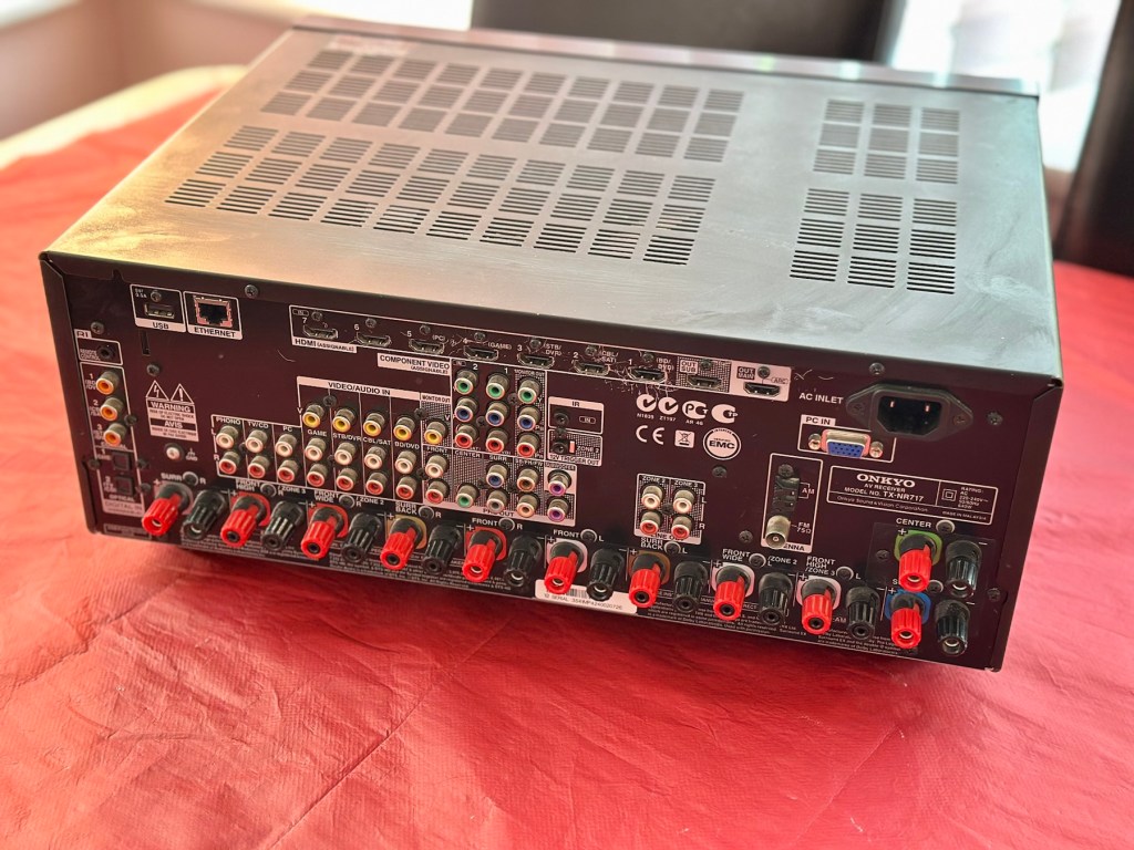
7.2-channel home theatre receiver, Internet-ready

A bit of a different one here, i get into work one day earlier this week, to be told that one of my colleagues in a different area (Nottingham) will be calling with something to discuss. That call occurred today and the discussion was about his home theatre surround sound system that had packed up on him, and would I be willing to look at it for him to see if I could manage a repair. Though it’s something I don’t usually do repairs on, I said why not? I need to look into other areas of repair and as long as it wasn’t urgent and there was no urgency, then I’d certainly look into it for him. It turns out there is no hurry and he will get the item down to me in the next few days.
So I now have a task, that I am really quite excited about. And for obvious reasons I want to do a good job.
Here’s a little bit about this item
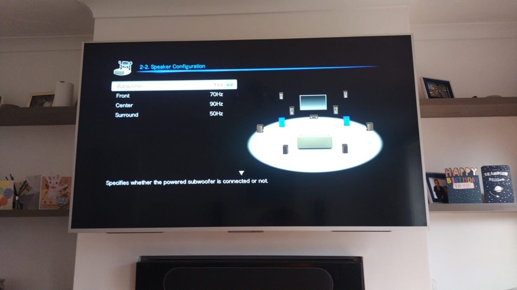
With the power to fill large rooms with THX certified sound, this cutting-edge receiver is ready to integrate and distribute entertainment throughout your home. More than a home cinema processor, the TX-NR717 allows you to access music on PC, stream from MP3 tunes, explore online radio, or connect your iPod/iPhone to one of two USB ports. You can distribute any of these various stereo sources to other rooms for house-wide entertainment. With a total of 10 HDMI connections, this receiver converges HD content from all your components – even your smart phone media via a front side MHL/HDMI – and provides easy input selection with InstaPrevue technology. HDMI also enables intuitive GUI with overlaid quick set-up menu. Video upscaling to 4K, Audyssey DSX seven-channel sound expansion, and Audyssey 2EQ room correction are all included. Sound quality is quite simply the best in class, with powerful WRAT amplifier, three-stage inverted Darlington circuitry, and discrete output stage components delivering an otherworldly entertainment experience.
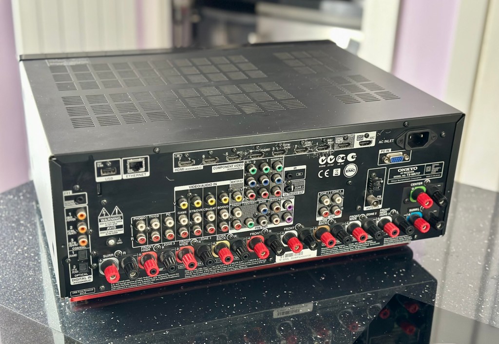
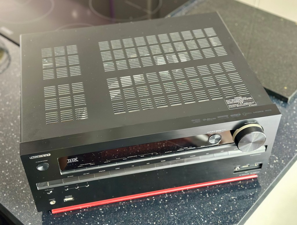
Onkyo TX-NR717 – AV network receiver – 7.2 channel – black
Release date: April 2012
Onkyo
I’m looking forward to this project, a little out of my comfort zone, but it’s the best way to learn about how these things work. And I need some exposure to these types of systems and the issues that can occur within them.
Assessment:
This unit has just about reached its teenage years, and if this can’t be repaired then the owner will be looking at his alternatives. However replacement units have also grown in both features and price now, so if this current box of tricks can be given an extended lease of life then everyone is a winner, and one less item gets to go to landfill.
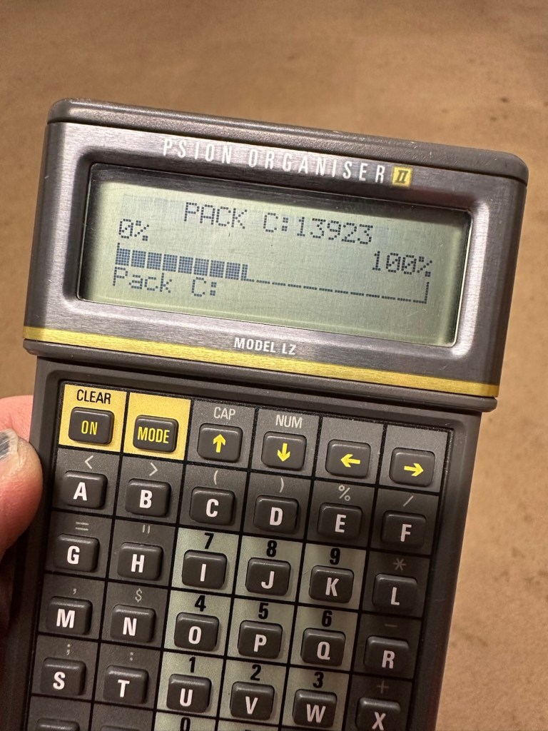
I have downloaded both the instruction manual and the service manual, so I am equipped with a full list of components as well as the official schematic diagrams of the circuitry layout. I’m suitably prepared for this one.
The report from my work colleague is that it was working fine up until a week ago when it would just not switch on. He has replaced the two quick blow fuses that he saw when he opened the unit, however the issue still remains. He hears clicking when he turns the system on, this could be an issue in the standby circuit, however I will have to wait to have the unit in my possession to investigate this any further.
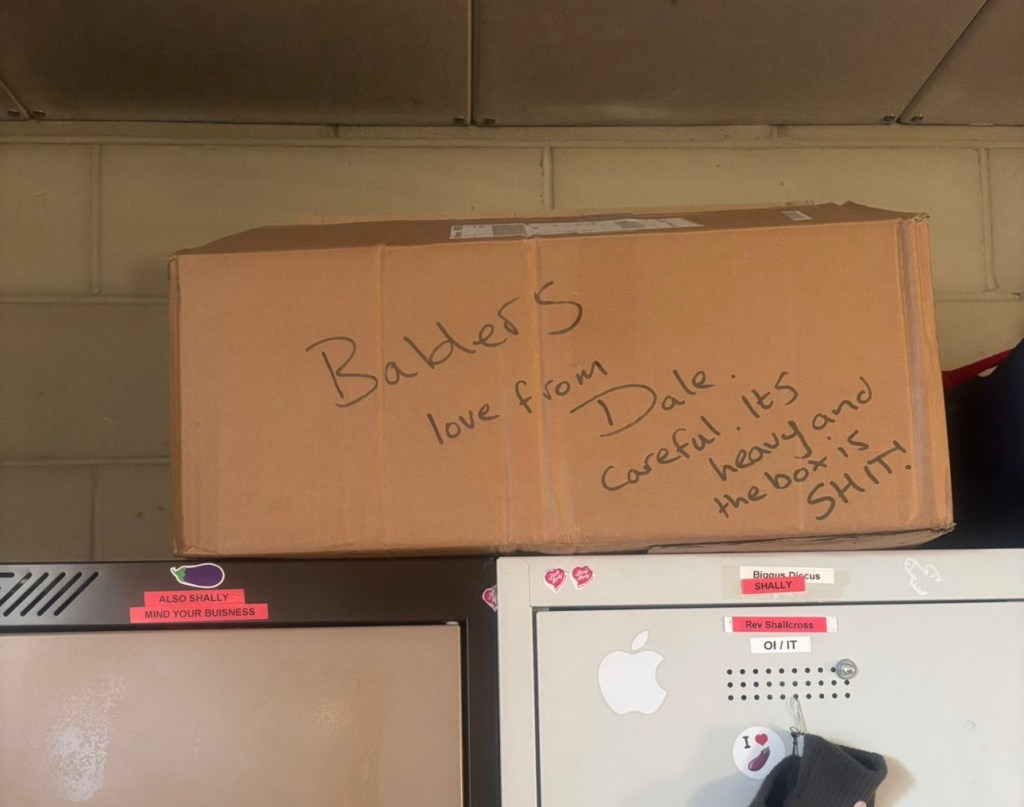
Just got a message from one of my colleagues at work to say the parcel from Nottingham has been collected. Just love the straight to the point way these guys inform me of any safety issues and concerns they may have 😂

And on opening the box, more surprises. Biscuits, they are my downfall, and don’t ask about the Aubergine, we won’t go there, that’s a private joke 🤦♂️

Right, serious head on now and I’ve plugged the unit into the mains and without touching anything at all, all I can hear is a metronomic clicking that appears to be emanating from the power board circuit area. This will be my first port of call.
Repair:
There are two well known issues regarding these units and I am going to look at both of these before getting in any deeper. The first issue is around the relay and its associated 150 Ohm resistor on the main power board, the second issue is around a defective capacitor on the standby board, and eliminating one issue will either highlight, or clear the other. If both issues are addressed with no change to operation, I will have to look in to the issue a little deeper.
Issue one relates to a problem with the relay on the main power board. Most people don’t realise this but pressing the power button on an Onkyo receiver does NOT turn off the power. The power button merely sends a signal to the MAIN CPU telling it to close a relay (to turn the system on) or open a relay (to turn it off). When you press the power button on an Onkyo and nothing happens (no clicks, no brief lighting up of the front panel) the root cause is often a blown coil in the main power relay.

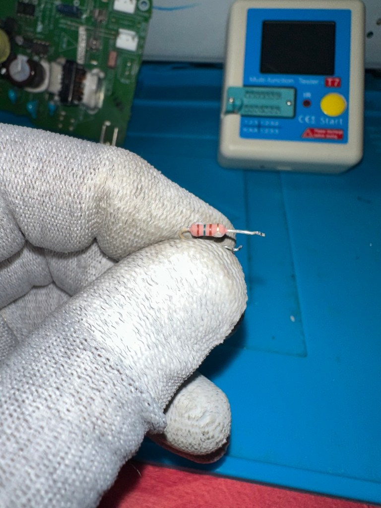
Beside the relay to the left is a resistor that should be reading 150 Ohms. This particular one is reading 144 Ohms so is reading a bit lower than expected. This could be sufficiently low enough to allow the relay to fail. So at this point this looks like a possible point of failure. Either way they need to be replaced before we can advance any further.
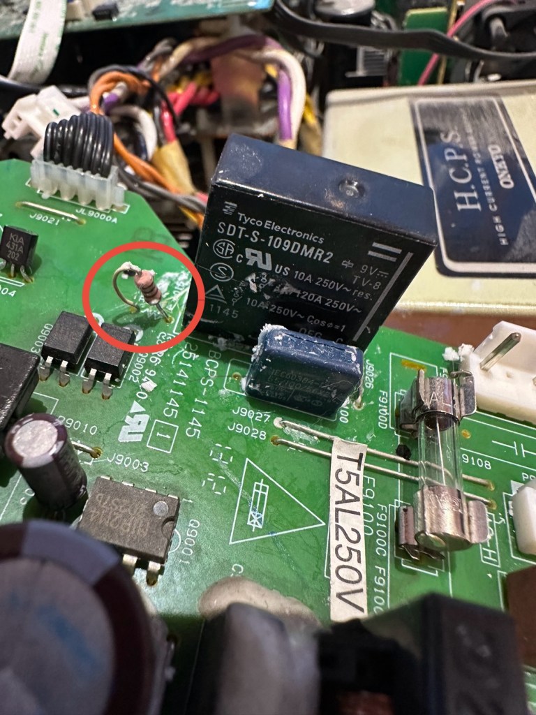
I need to obtain these parts, the relay will need to be shipped from China, and I need to check my resistor stock to see if I have a suitable replacement resistor. The relay also should have a similar resistance to the resistor beside it, the healthy range for the relay is between 80-200 Ohms.

I have removed both components from the board to test them out of circuit.
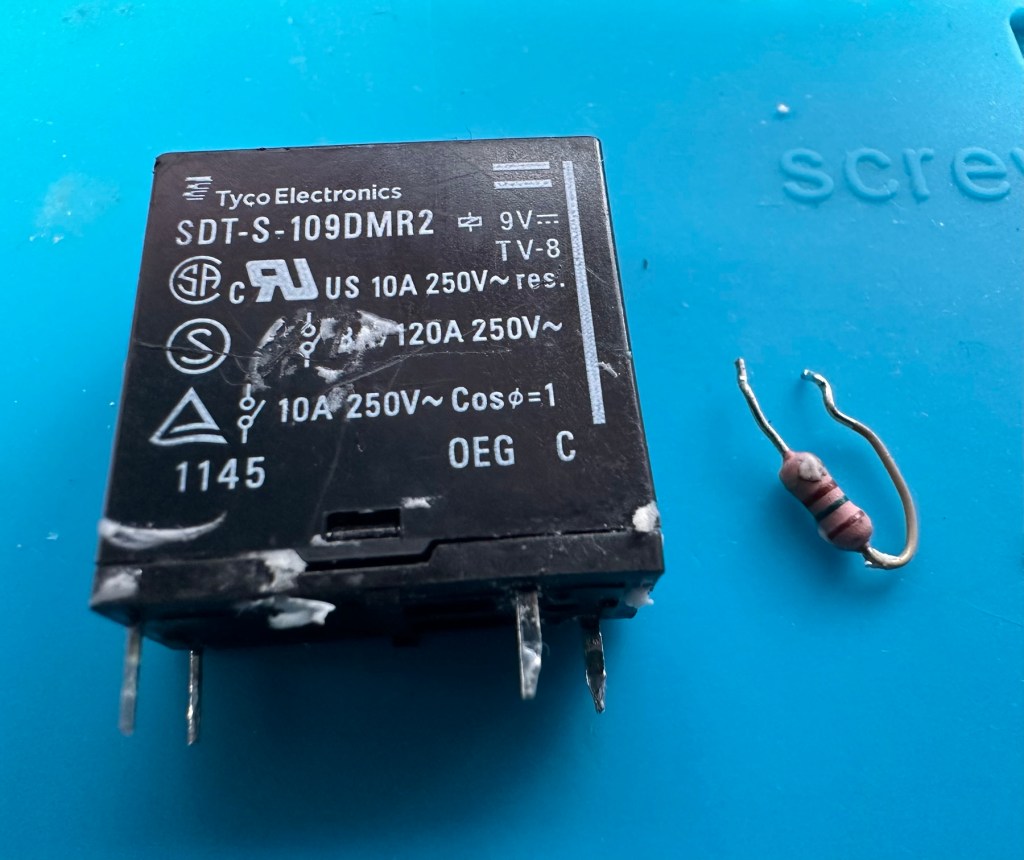
The resistor beside the 9v relay is a 150 Ohm rated resistor. This one reads at 144 Ohms and is to the lower end of the rating of +/- 5%, it would probably suffice, but i’m going to replace this one just in case. The only other resistor in this circuit is a 47 Ohm resistor and that reads exactly as it is rated, so there is no issue there. I believe the bone of contention here is that the relay is 9v sitting upon a 12v power rail. This is probably the reason issues have occurred with these units in the past, and looking at a number of forum posts, it is quite acceptable, even recommended to use the higher voltage 12V versions. I’m sticking to the original design on this repair though, I can only presume the 150 Ohm resistor placed just before the relay has something to contribute in controlling the operation of this relay. Maybe that’s a design fault within this model, I just don’t know!

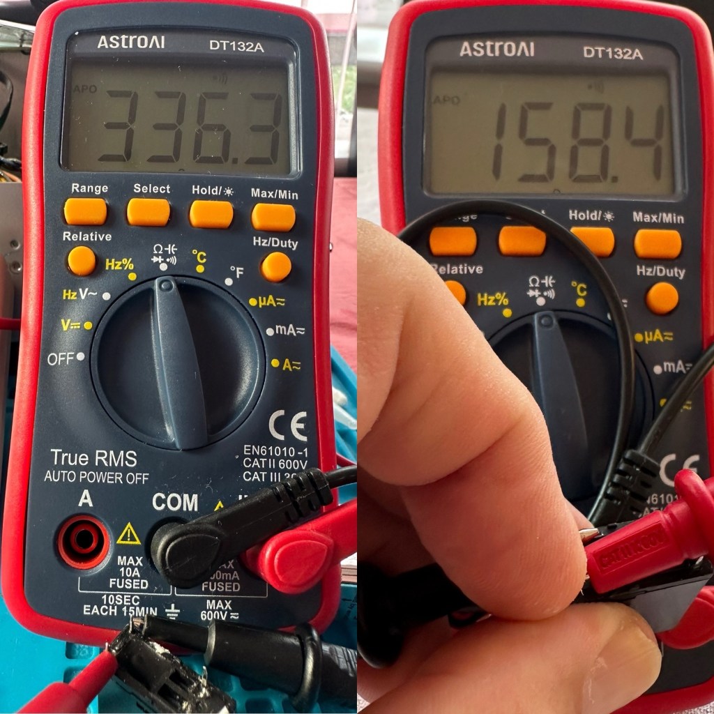
I have tested the relay using a multimeter and a 9v battery. I have used the battery to short across the power poles where I can hear the relay clicking, but when the relay is on there is no continuity across the other two pins when there should be, this isn’t happening so I suspect this relay is stuck in the open position. The Ohms rating across the pins shows 336 Ohms, so i am lead to believe this could be a problem with the coil inside it, as it shouldn’t really be that high. I understand from what I have read, that a rating between 80-200 Ohms is classed as acceptable, and outside this range could indicate that there is an issue. I’ll just have to wait until the new relay arrives and carry out some tests to see the comparison between the old and the new relays.

I’ve dismantled the cover from the relay to get a look at the coil. In the little video below you will see the coil switching, however you will also see the contacts meeting but there is no continuity. The contacts have a coating of contamination on them probably from age or arcing, it looks like a carbon deposit, as when they adjoin there is no contact made, no flow or continuity, unless you put light pressure on the contact and then you get the continuity. It is at fault, it shouldn’t be doing this. A clean of the contacts might breathe some life into it, however give it a couple of months and you’d probably have to remove it again, and the contamination isn’t the only issue, don’t forget the relay reading that appears too high. A new relay costs less than £4:50GBP delivered from the other side of the world, so I might just as well go for a new relay. It makes sense.
I’m not going to venture any deeper into this unit yet, not until these components arrive and I can get them back into place. I want to move through this fix confidently and slowly, have a better understanding of what is going on and not leave myself confused with bits and pieces everywhere, clueless to what is occurring. I wouldn’t achieve anything by working like that. Knowledge is king here and I’m here to learn. And I do now have the schematics available to follow.
I’ll have to wait about 2 weeks for the relay to arrive so I’ll just have to put this repair to one side and on hold until then.
Ok the new relay has arrived and the first test I did on it was to take an Ohms reading of the coil side. Now if you have paid attention, you will have seen that the old relay was reading 336 Ohms when it should be somewhere between 80-200 ohms. This new relay is reading 158 Ohms and I feel a lot better about that, it falls right in between the expected spec.
And if you want to see the relay actually working and displaying continuity then have a browse at this video below, the polar opposite to the first video I posted above 👆
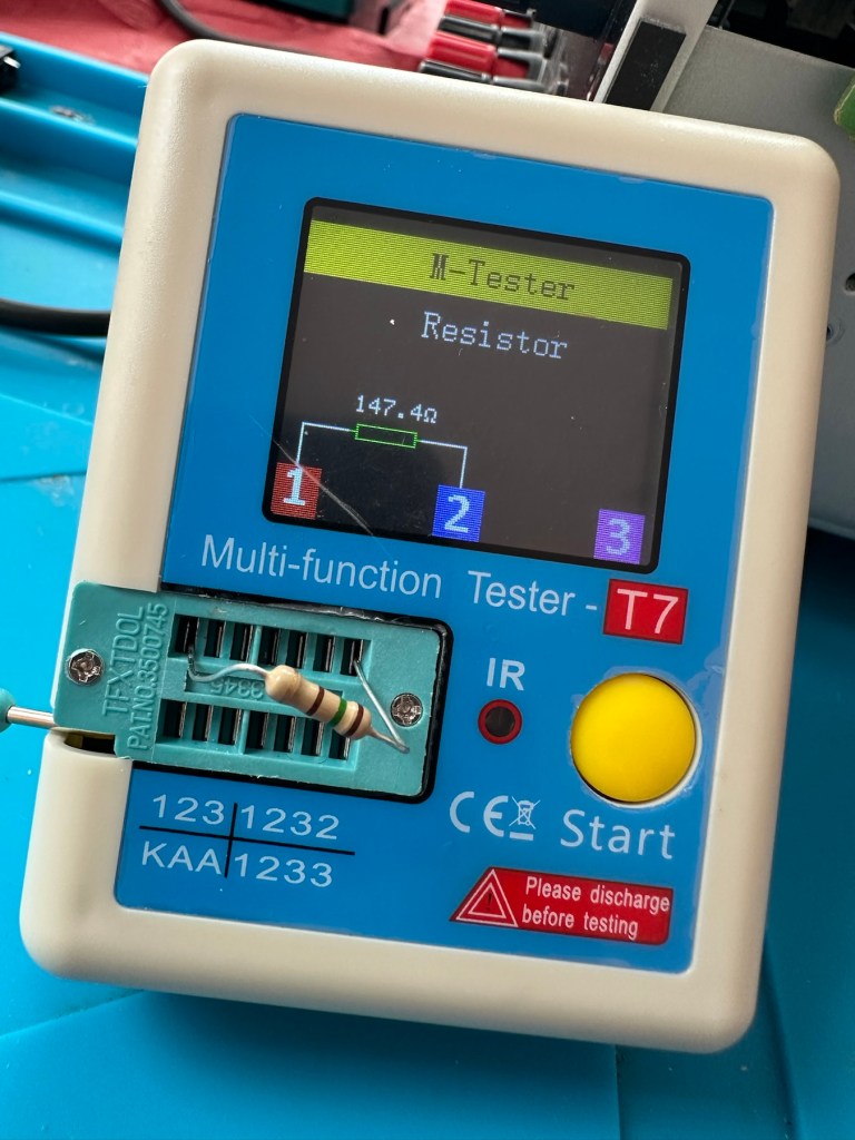
The resistors I ordered have now come through and have been tested, I have a couple of candidates displaying better test results, so we can now look at getting these two components back in place to see what occurs.
I’ve put in place a new resistor, slightly higher value than the previous one coming in at 147.4 Ohms. It falls within the 5% tolerance so should be fine.
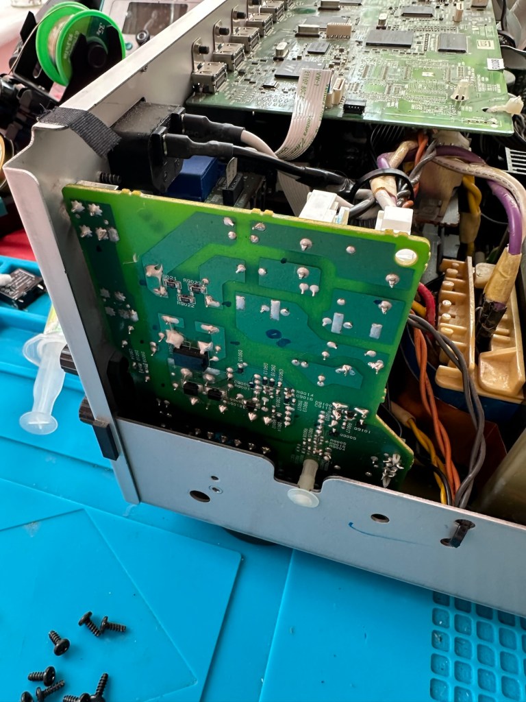
The relay has been soldered back in place, really simple just four points to solder and we can now reassemble the power board back into the chassis.

I’ve taken the unit into the garden at my wife’s request, as I have to use some high pressure air to give it a good blast to get rid of some dust and furballs. This has worked well and quite a dust cloud was witnessed across the garden, it’s fair to say it’s a lot cleaner inside than it was.
I’ve now put the case back on and the unit is now sealed from prying eyes and inquisitive fingers. I’ve given the entire case a good polish and I must admit it is looking nice and shiny and very presentable. I just have to hope and pray that it turns on. I see no reason as to why it shouldn’t but you just never know. You can always fix one problem only to be chasing it around the system as it develops into another fault, repairs can sometimes go like that.
Let’s plug it in and see what happens 🤞
Result:
I’ve plugged it in and turned the power on. No bang, only silence, just a single click when the power went on, this is good. When the power is turned off you hear the standby relay do the same, all is as it should be.

The standby relay has clicked in when turned on at the power socket, and is not repeating that metronomic sound that was there originally. Superb. Now to turn the power button on, on the front panel.
We have a display. Excellent it is working.

All buttons are operational, I don’t have the surround sound speakers as they are at the owners house in Nottingham, i also don’t have the remote here that also allows me to do other tasks, however that is not important as the unit is now operational and displaying what it should, and once it goes back into his media wall with all his speakers and other related sound and Av equipment, i am confident beyond doubt that it will be operating just as it did prior to this issue developing.
I will be handing it back with the advice that should the issue occur again we look at updating the relays with new 12v versions to replace the current 9v ones. But I doubt the problem will re occur, and this repair should see out the next few years at least and by then this unit will probably be sold, or passed on to someone else when he decides to upgrade his system.
Below is the little video I sent my colleague showing him the unit now working
But for now, it works. I am pleased as punch with this repair as I have stepped out of my normal comfort zone here. I have been extra vigilant, studied many a schematic diagram and learned a lot from this project. I didn’t rush ahead of myself and took this repair one little bit at a time, testing all along the way and addressing each issue in the order that it has arisen. And I’m damned happy with that.
It’s been a learning project for me, and I’m glad I’ve undertaken it. Life is for learning, and I’m living that life.
Many thanks for passing by, as you well know it is always very much appreciated.
Edit:
Today the 29th July I have had a message back from my colleague to say that he now has the unit back in his media wall. And I’m pleased to say it’s working perfectly. He’s very pleased and so am I.
He’s pestering me to bill him, but I’ve told him that I’m only taking one currency and that’s not money or crypto. No, my method of payment will be in Biscuits. I told you I’m a Cookie Monster and this entire repair only cost just £4:17GBP. That’s not a lot of Cookies, but it’s credit in the bank if these guys need any further repairs carrying out. Word of mouth, works wonders.


You must be logged in to post a comment.