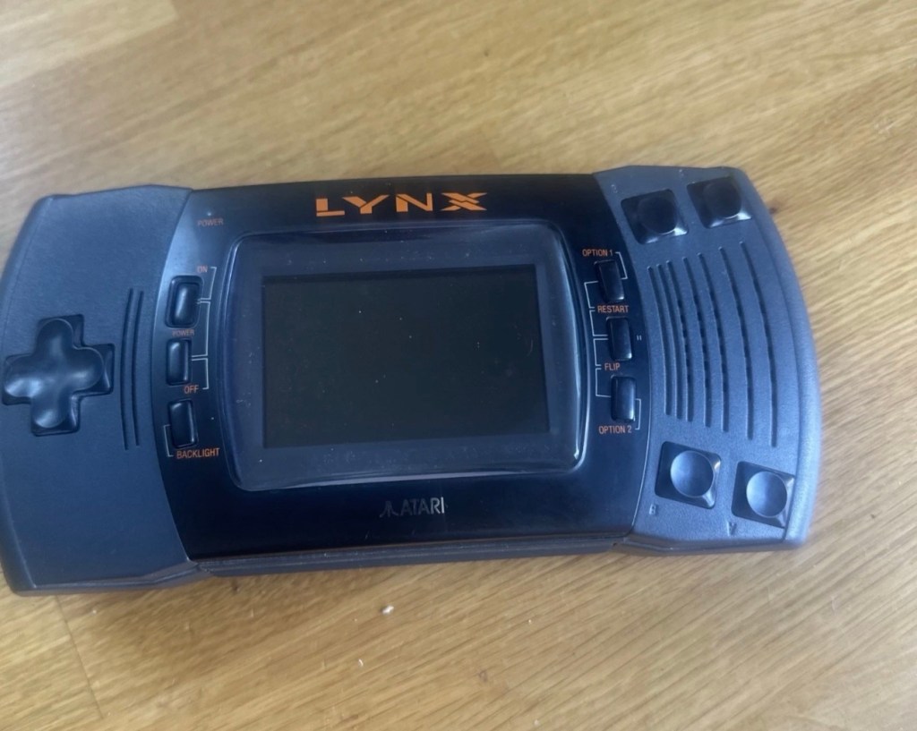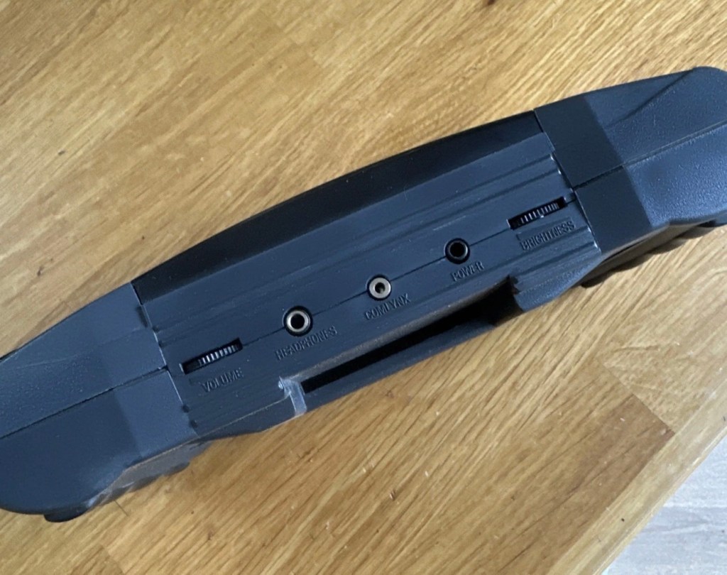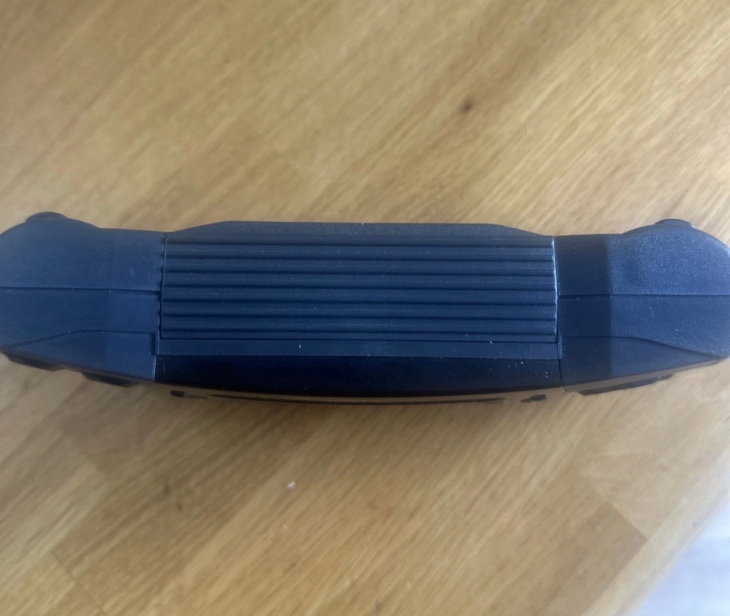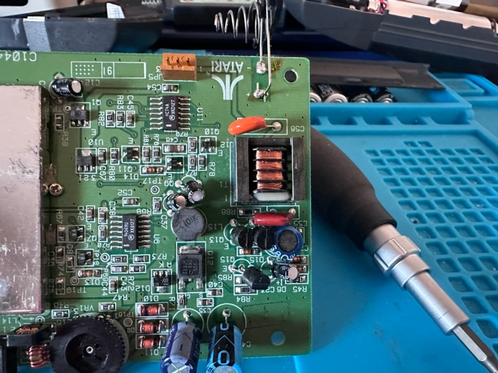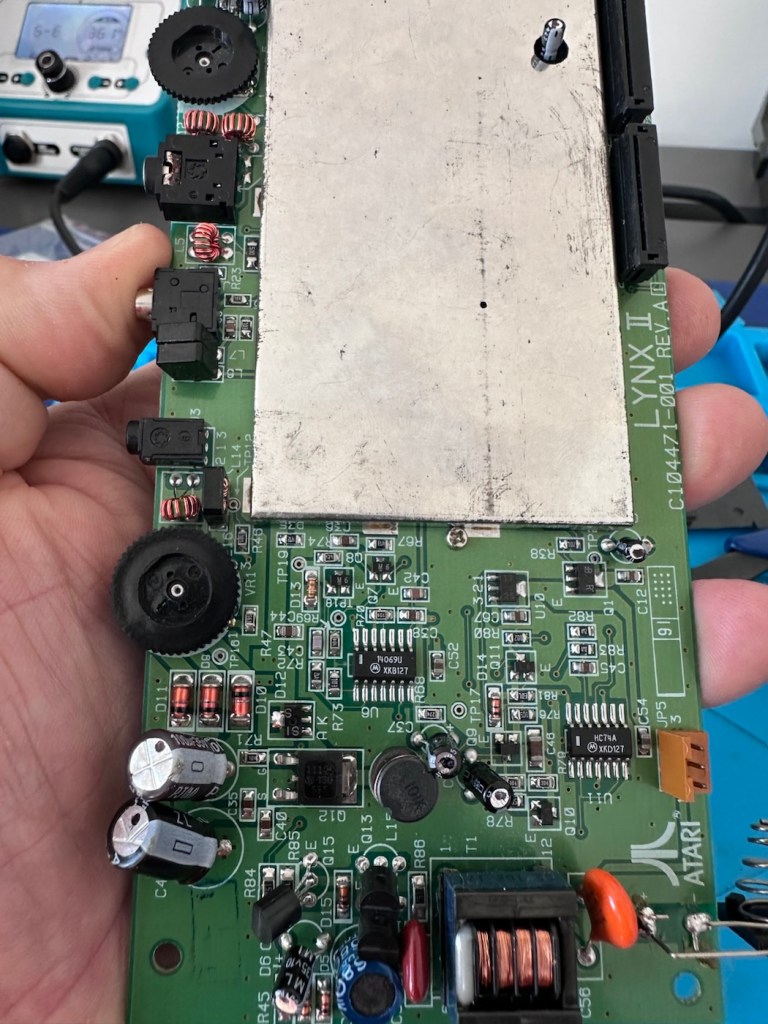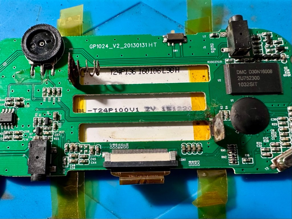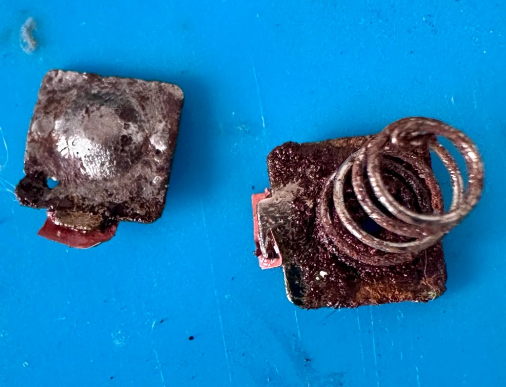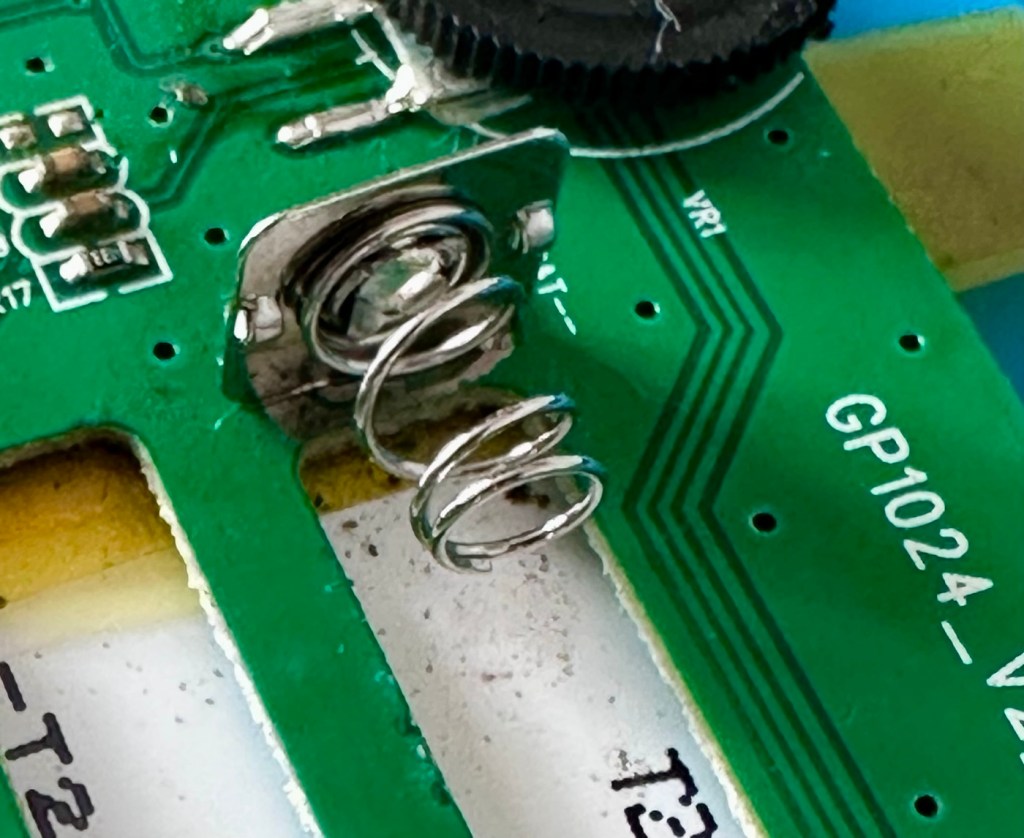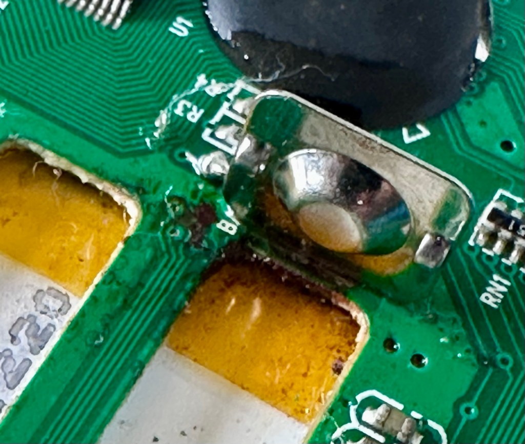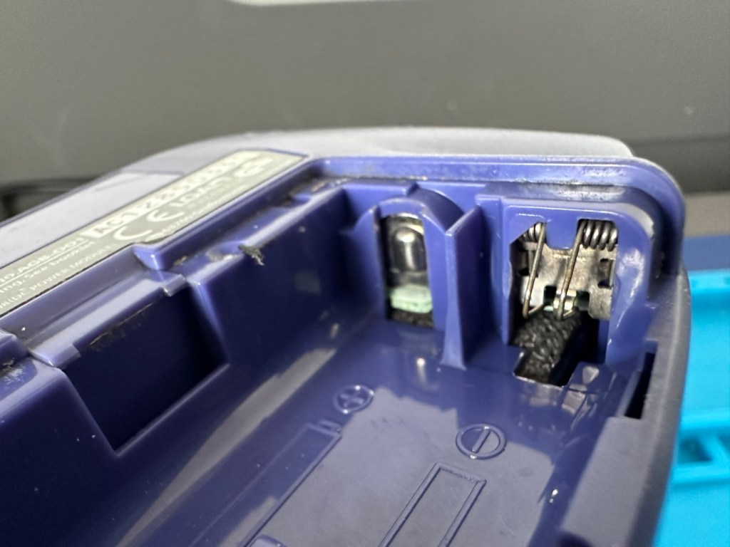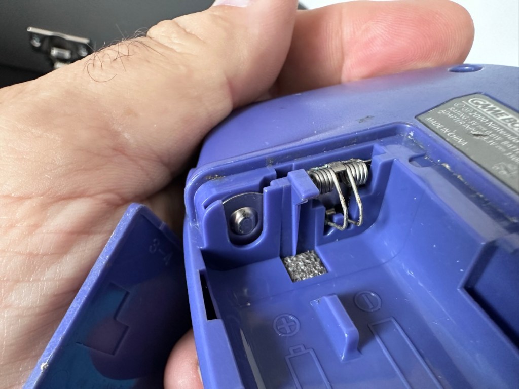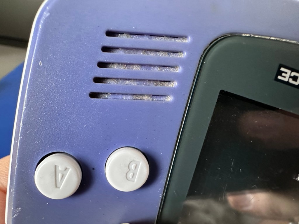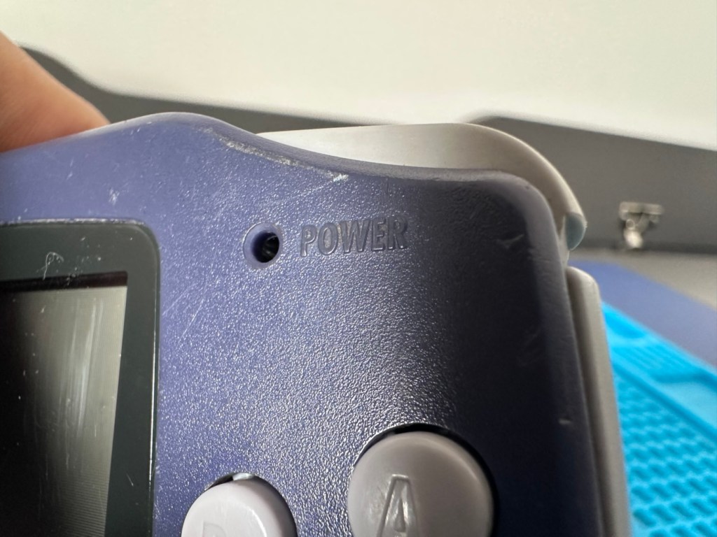

Atari Lynx 2 handheld games console

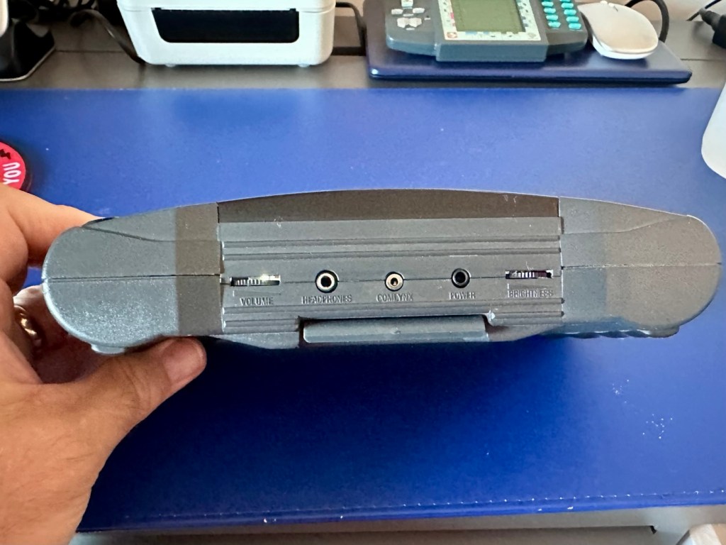
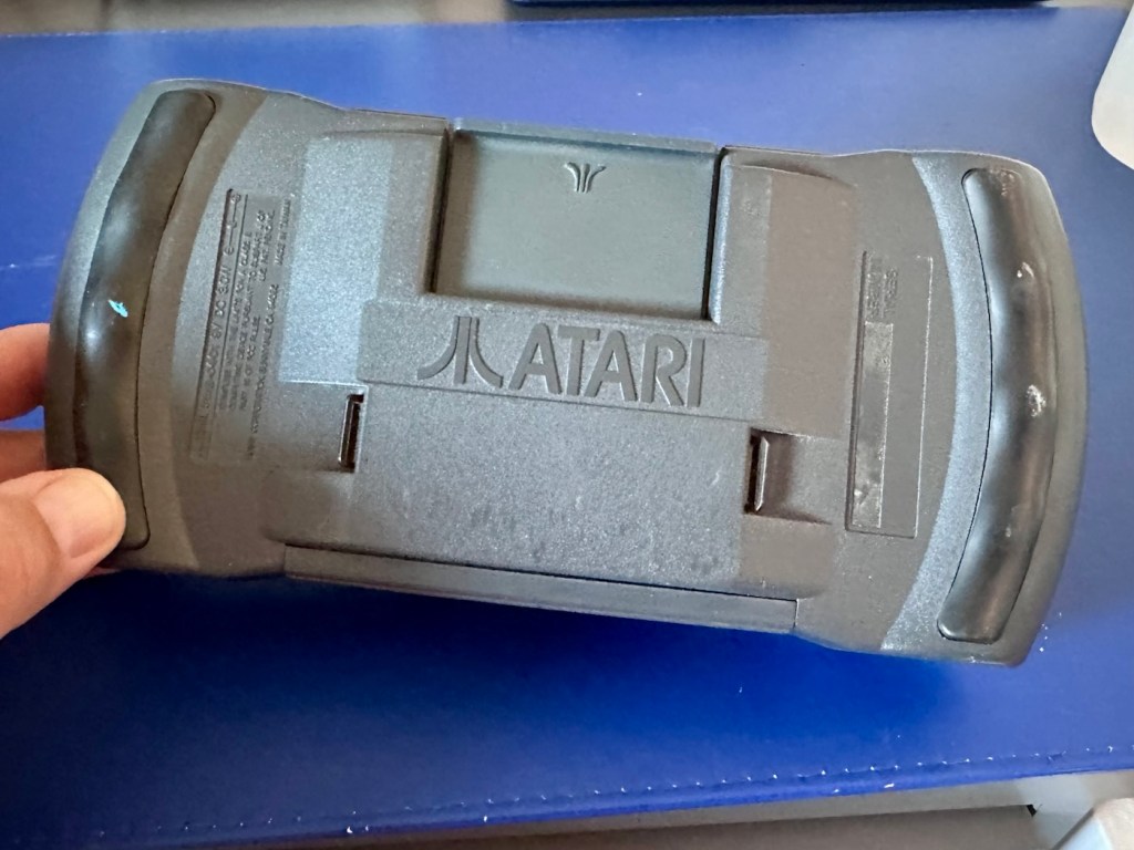
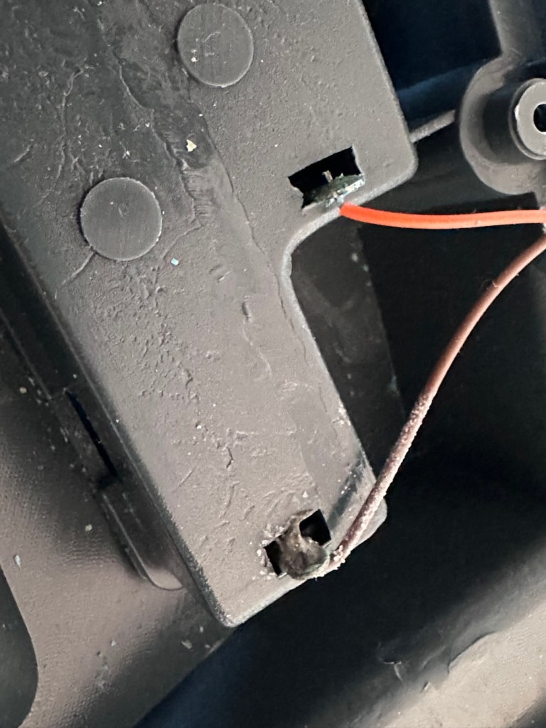
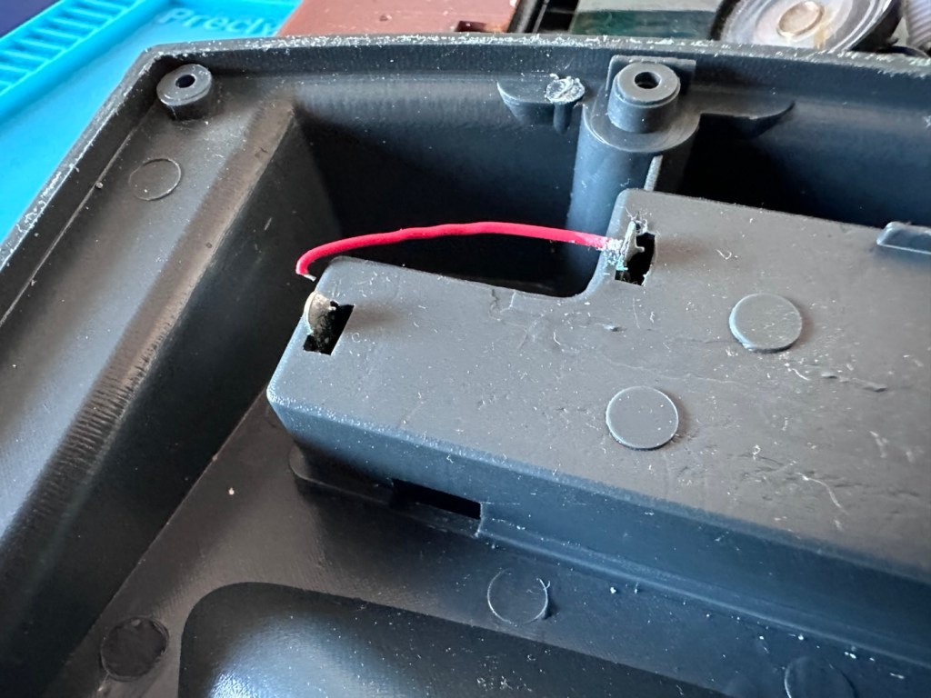
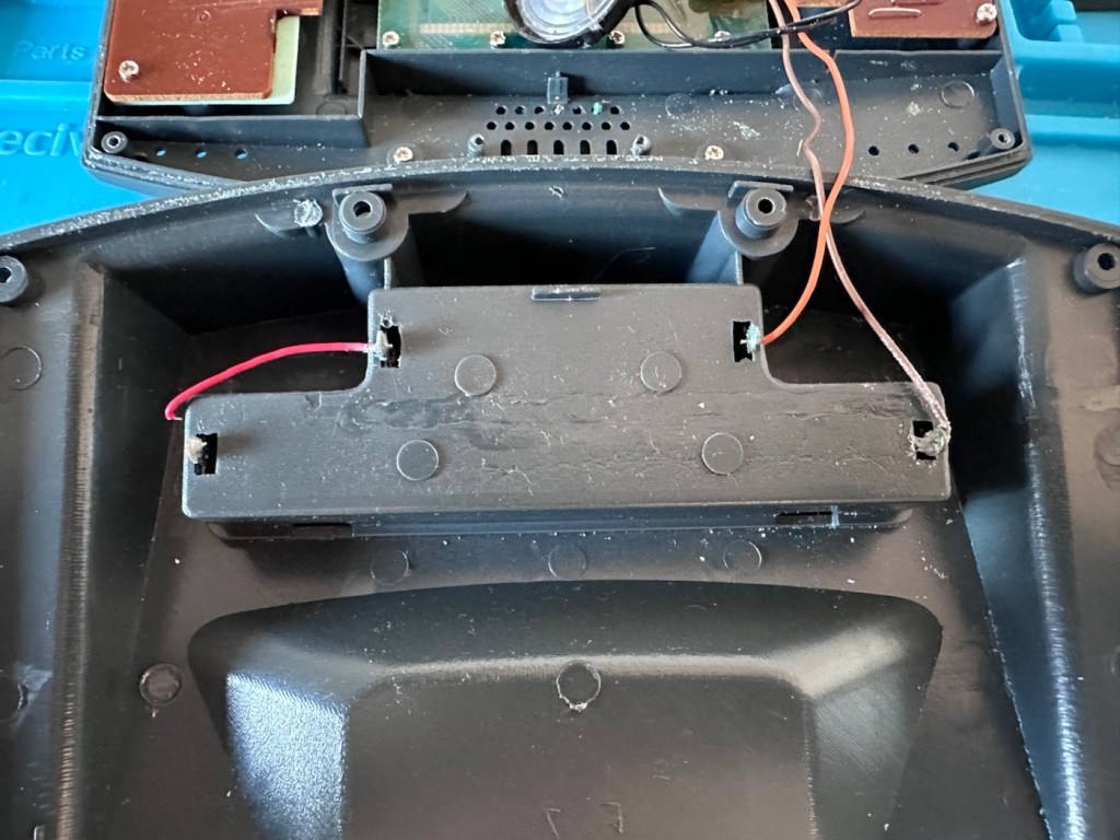
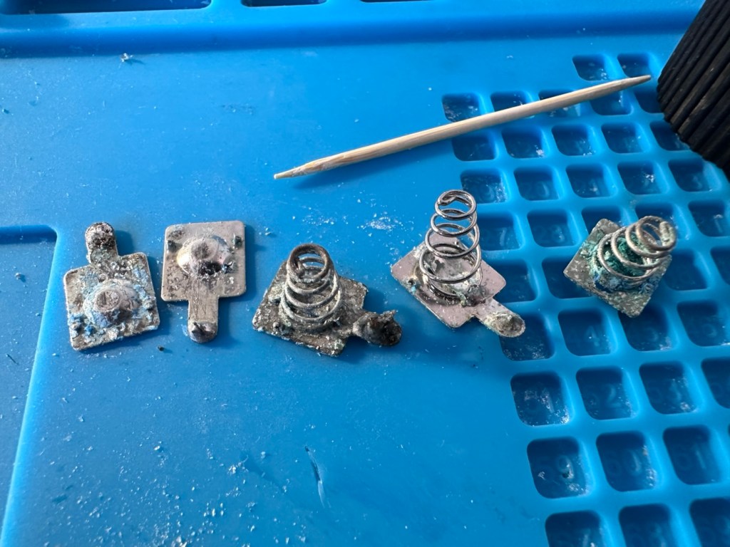
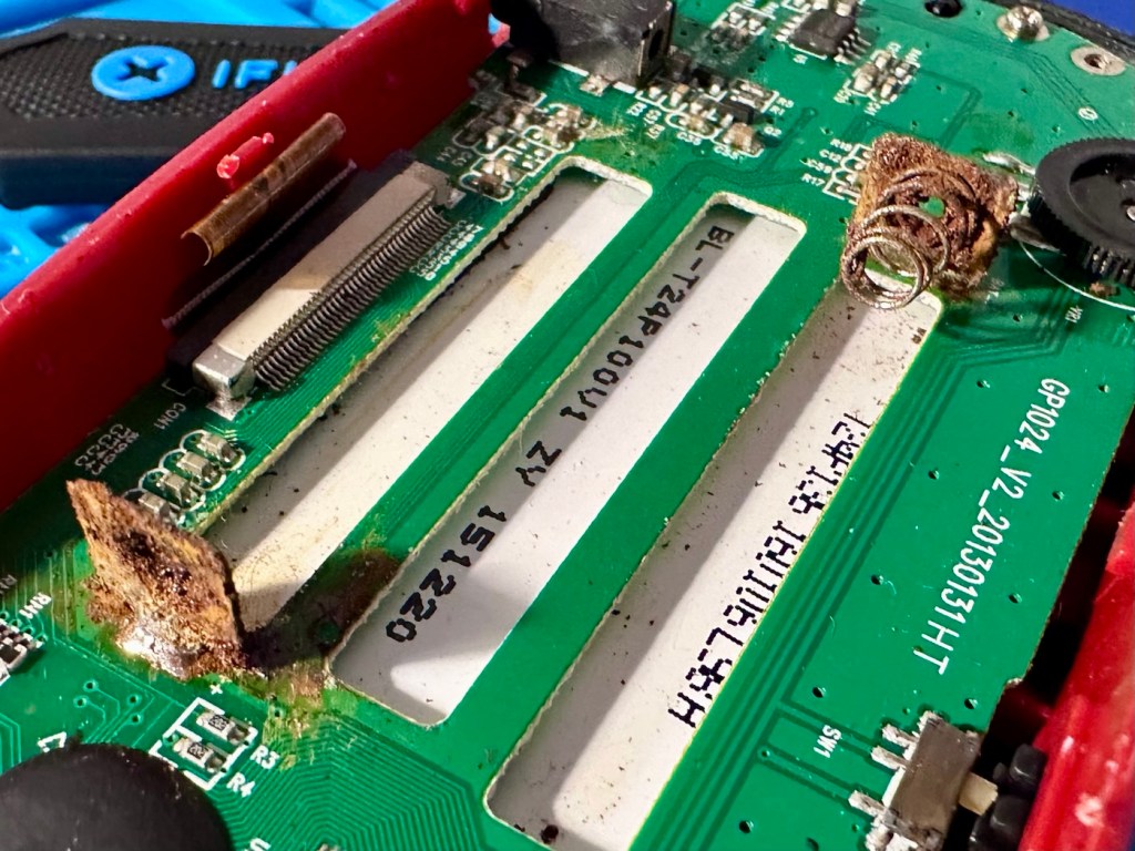
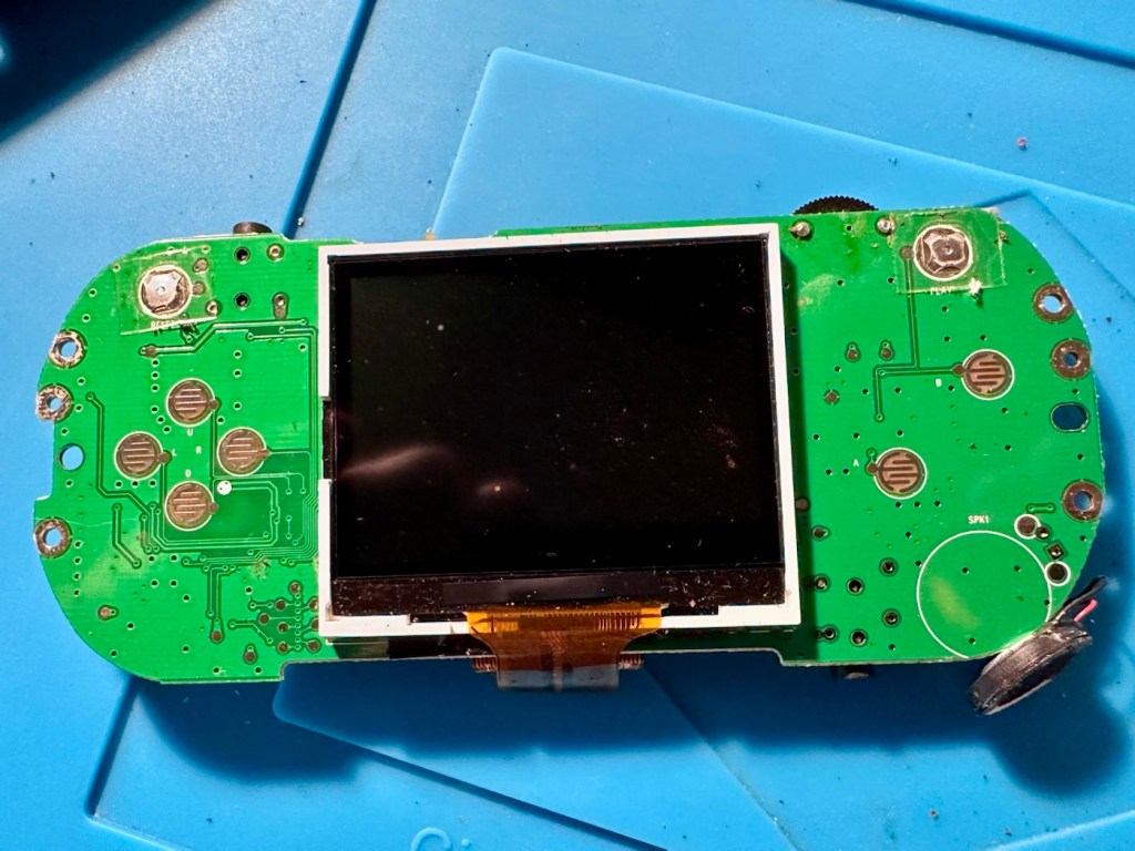
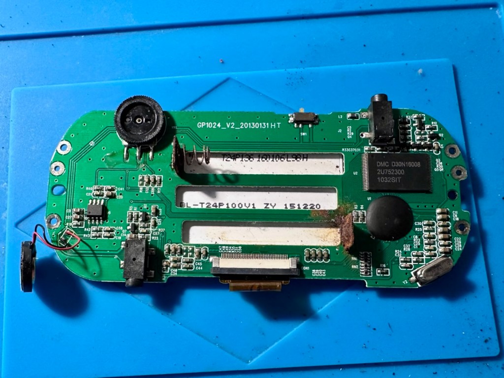
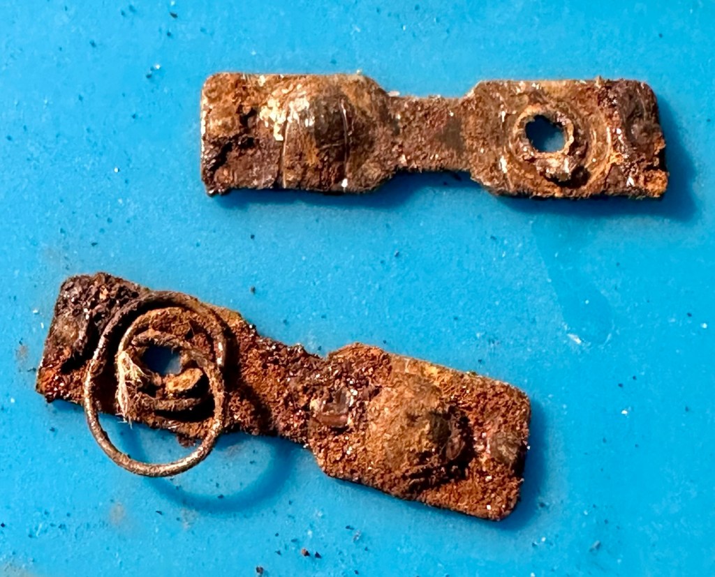
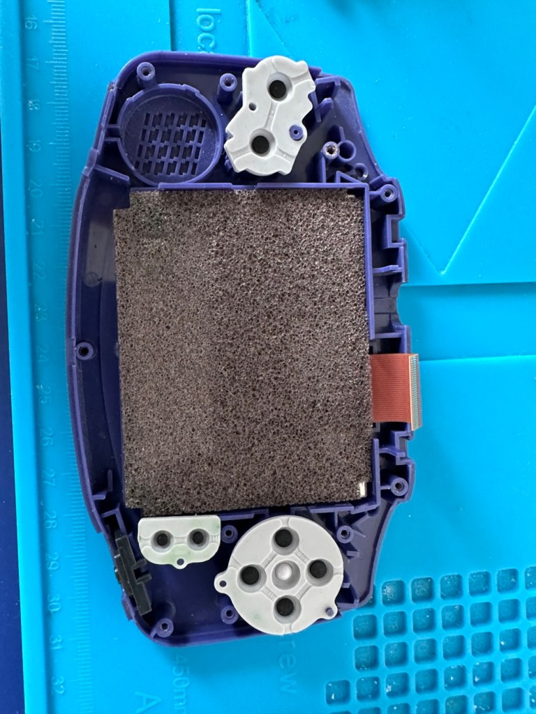
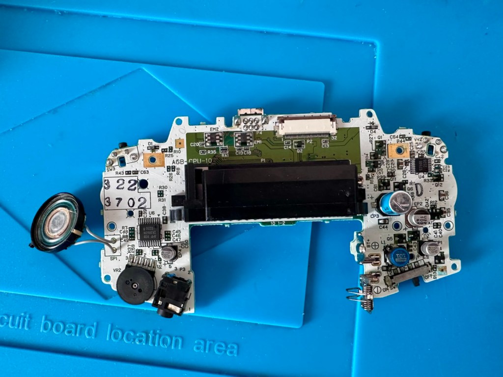
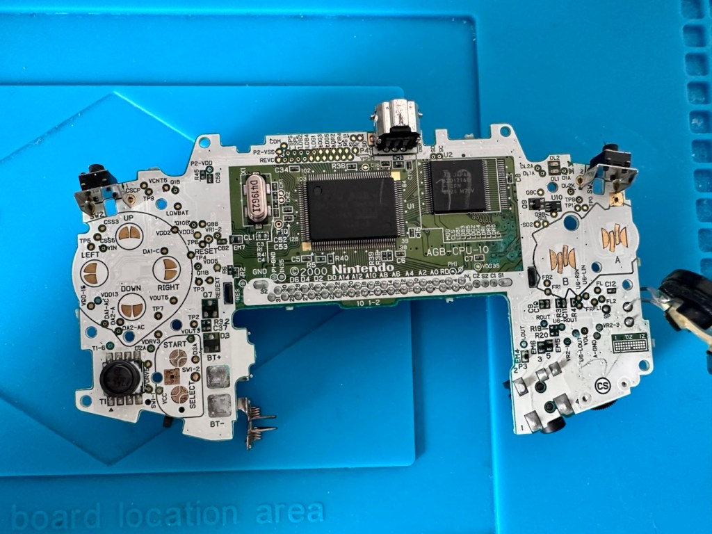
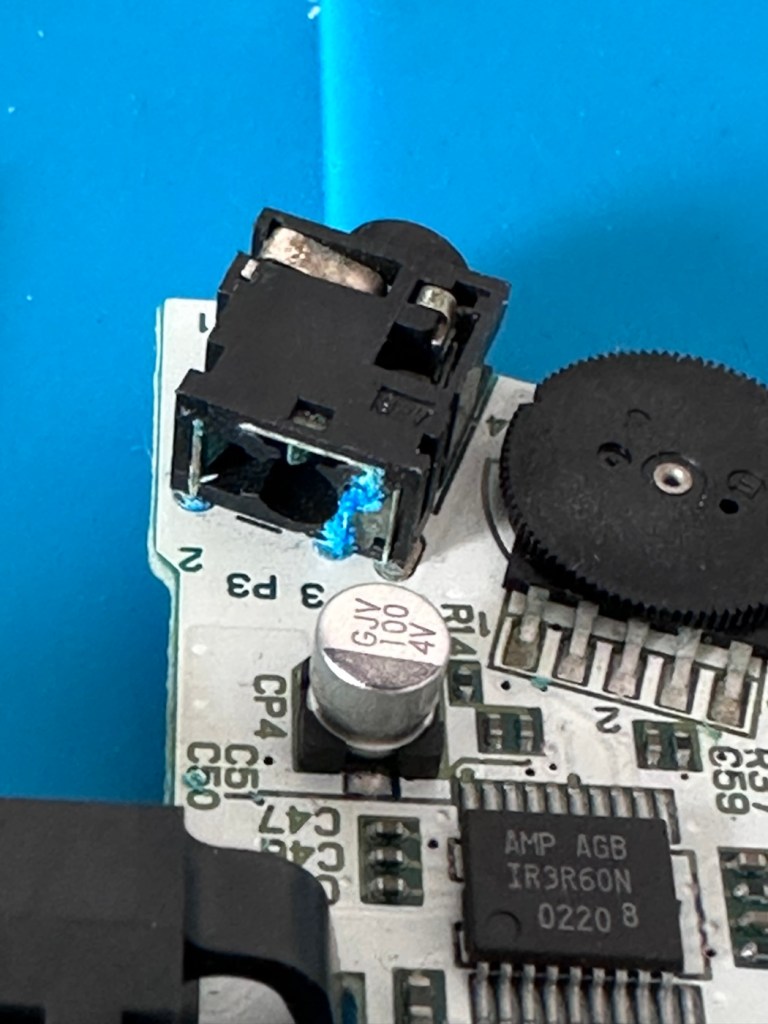
Meet Mikey, and Suzy! Well it’s actually an Atari Lynx II from 1991. Mikey and Suzy were the names given to components within the console. Anyway it doesn’t work, so let’s try to breathe some life into it.

What the listing stated:

The product is an Atari Lynx 2 handheld console, originating from Japan. It is a spare or repair item, as it is not in working condition. The package does not include a charger. This vintage gaming device, released by Atari, offers portability and gaming capabilities. Ideal for collectors or enthusiasts looking to fix or restore a piece of gaming history.

EBay

It’s a faulty item, one of many I have been chasing over the last few months, however their resale prices even when faulty, can command some quite hefty prices. I’ve managed to purchase this one at £65:00GBP and that is a price I am content with, as some of the recent ones I have seen went for a higher price even with parts missing or body damage. Cosmetically this one appears to be in a good condition with everything intact. However, the actual fault has not been declared, just that it is faulty and not working. I will have to do a little fault finding to pinpoint the issue, though I suspect initially that a full capacitor change will be the order of the day.

I want this to be part of my personal collection, alongside the Lynx 1 that I also have.

Here’s a little bit of information regarding this unit:

The Atari Lynx II, released in 1991, is the sleeker, redesigned version of Atari’s pioneering 16-bit handheld color console. It addressed original flaws by offering improved battery life, a backlit LCD, and stereo sound, while retaining impressive hardware features like hardware sprite scaling and a unique “lefty” flip mode. 

Key Features and Design

The Lynx II packed advanced technology for its time, including several highly unique design choices:

The Display: It features a vibrant 3.5-inch color LCD. Unlike the original, the Lynx II included an option to toggle the backlight off to save battery. 

Left-Handed Mode: Because of its symmetrical control layout, the entire system can be flipped 180 degrees. The internal software features a “flip” button to invert the screen, converting it into a truly left-handed console. 

Vertical Gameplay: Some games, such as Qix, are designed to be played holding the system vertically like a book, taking advantage of its unique design architecture. 

Comlink Play: It supports up to eight players for local multiplayer over “ComLynx” cables. 

Hardware & Power Specs

Processor: 16-bit custom CMOS chip (nicknamed “Mikey”) running at 16 MHz.

Graphics: Custom graphics chip (nicknamed “Suzy”) featuring hardware sprite scaling, zooming, and distortion.

Battery Life: Runs on 6 AA batteries, which deliver about 4-5 hours of gameplay with the backlight on. Due to this high power consumption, an AC adapter was a common necessity. 

Courtesy t’internet

So, without any further suppositions as to what’s wrong with it, let’s just await its arrival to carry out a full assessment.

Assessment:

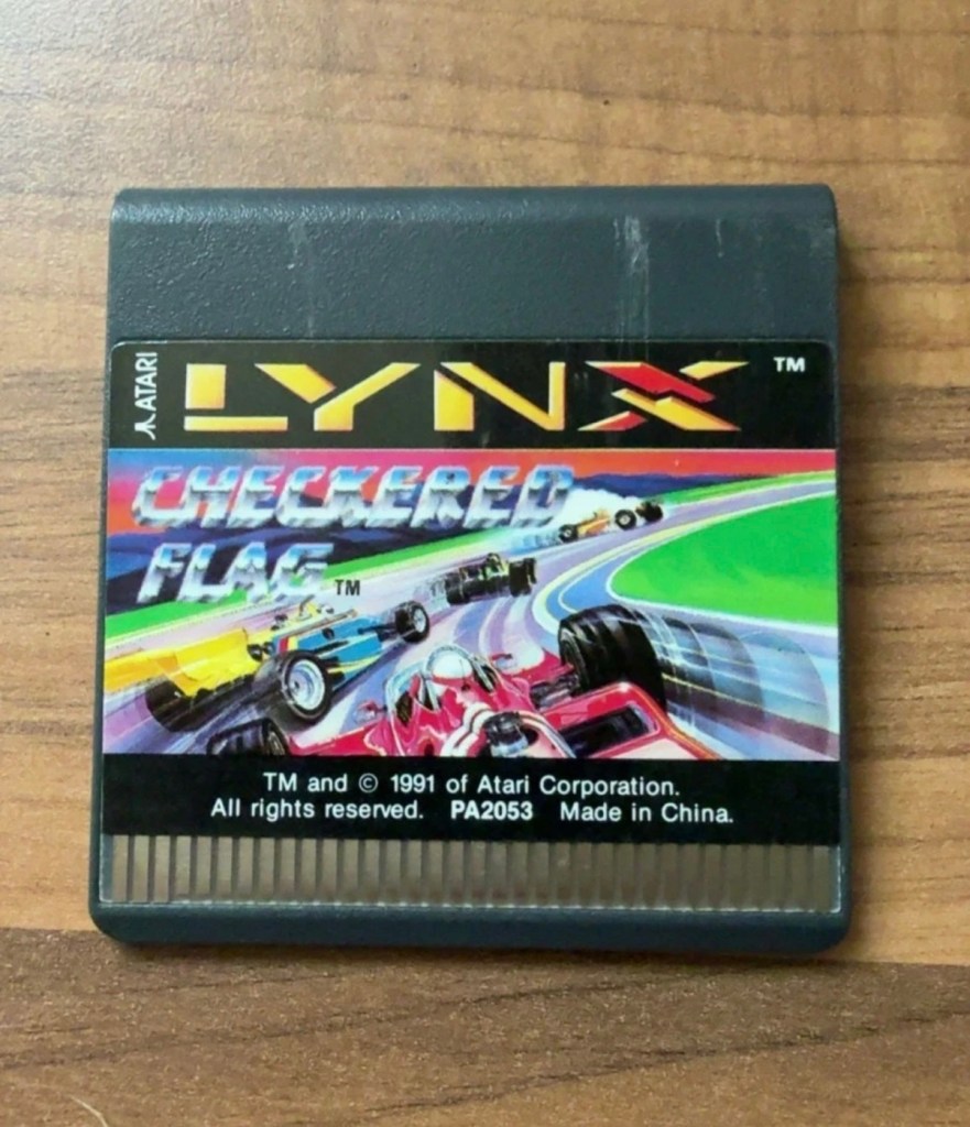
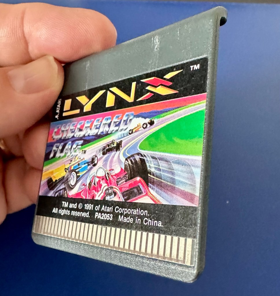
I believe that to do a proper test on these units you have to have a game cartridge installed, this is my first issue, I don’t have any cartridges so I have had to purchase the cheapest one I could find for testing purposes. I’ve managed to pick one up for £11:00GBP and to be honest that isn’t too bad. It may well be the worst game they ever produced, who knows? But it will be fine for testing purposes.

Checkered flag for the Atari Lynx

Well, we still wait. Two weeks down the line and only the game cartridge has arrived. Not much I can say about that apart from it looks ok.

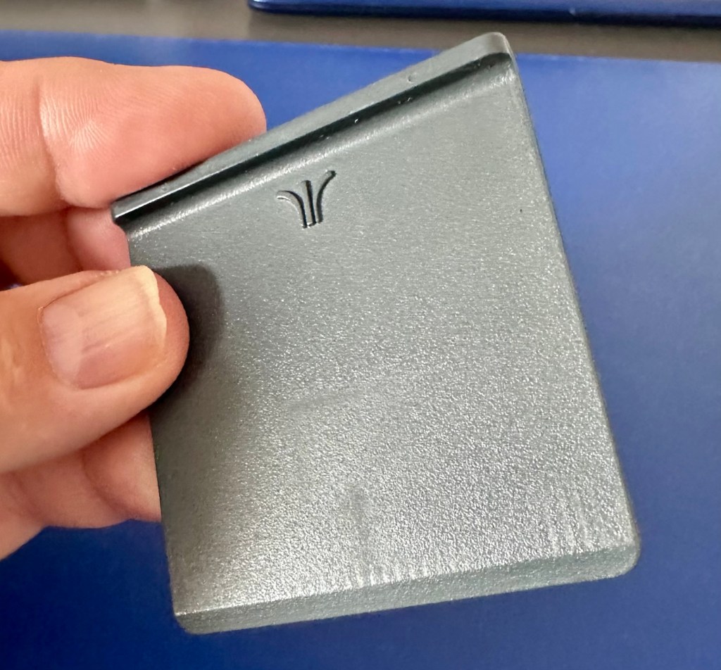
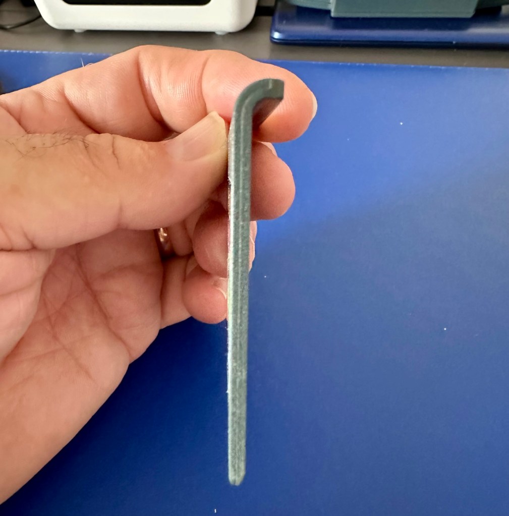
If the game doesn’t function there is not a great deal I can do here. As you can see it’s just a wafer thin plastic plug with no user access available. About the only thing you can do is clean the contacts.

We just need the console to arrive now……

And it’s arrived and to be quite honest it is in a good condition cosmetically, and for an item that’s now 35 years old it has been well looked after. No need to put any batteries in as there are already a fresh set in there, I have checked their voltages and they are fine. 6 x AA batteries turning out around 9 volts, the units requirement.

As I have previously stated, without a game cartridge installed the unit does not turn on. When a game is installed and the unit is turned on, I get an audible short “click” and the back light of the screen comes on, I get nothing else and am unable to get any sound or adjustment on either the volume or screen contrast dials.

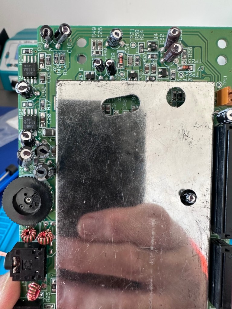
It’s looking very much like either a screen issue, or an issue related to the failed capacitors on the main board. There is one particular capacitor “C41” that controls the main power board that is notorious for failing. I will check this initially to see how it is fairing, if it is ok I will make my way through the board checking other components as well as looking for other points of known failure such as weak solder joints.

Repair:

Firstly, let’s get into the unit, and this requires the removal of five screws in total.

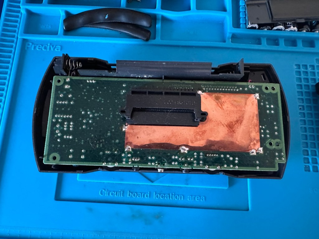
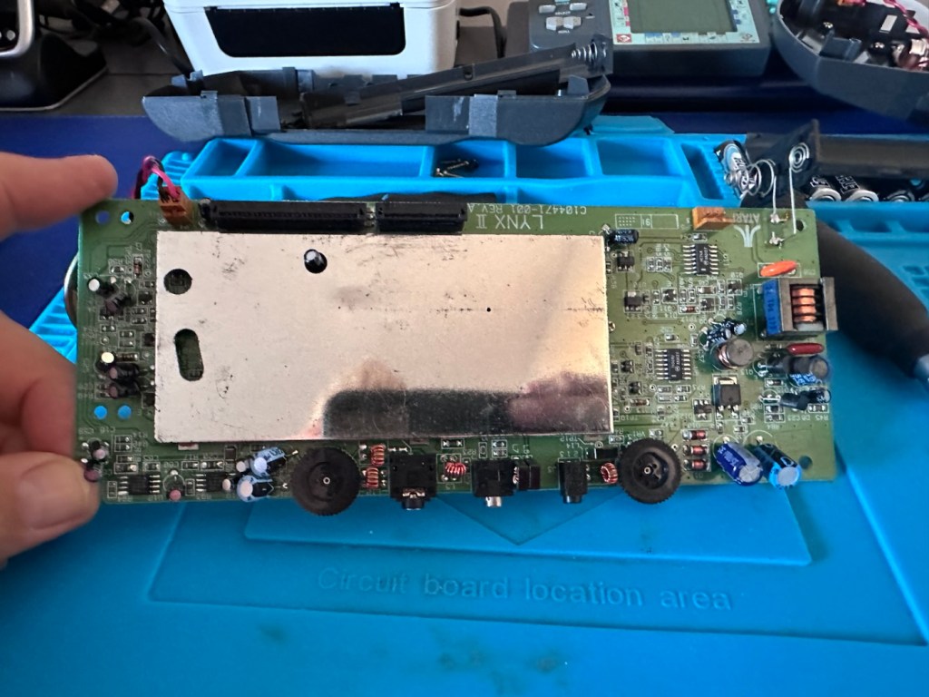
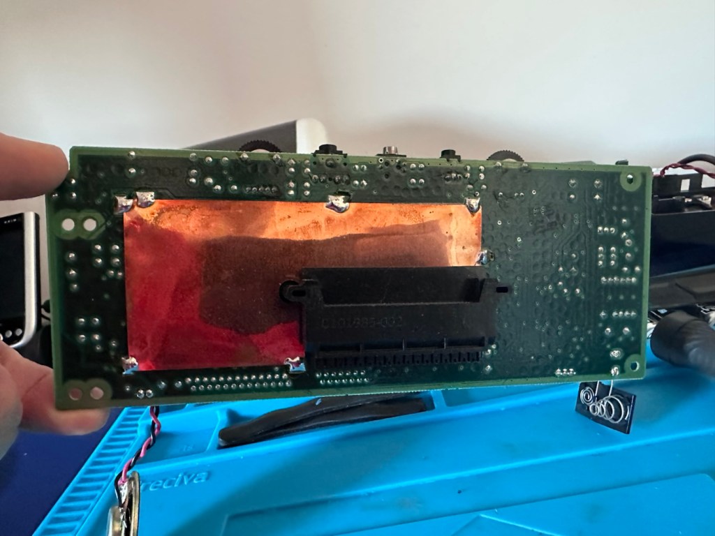
The back should then lift off. Carefully remove the two screen ribbon cables, the power jack and the speaker jack and the whole of the main should just lift out.

A word of warning here. The power side of the board has a number of points that if touched will give you a nasty jolt of many hundreds of volts, a very quick and potent shock and you will certainly know what’s happened. Be very careful handling anything in this area, especially around the capacitors, and always make sure you bleed the power once the power source has been removed. If you are working live in this area, please be very careful. It’s amazing that just 9 volts of injected power can create such high voltages. You have been warned!

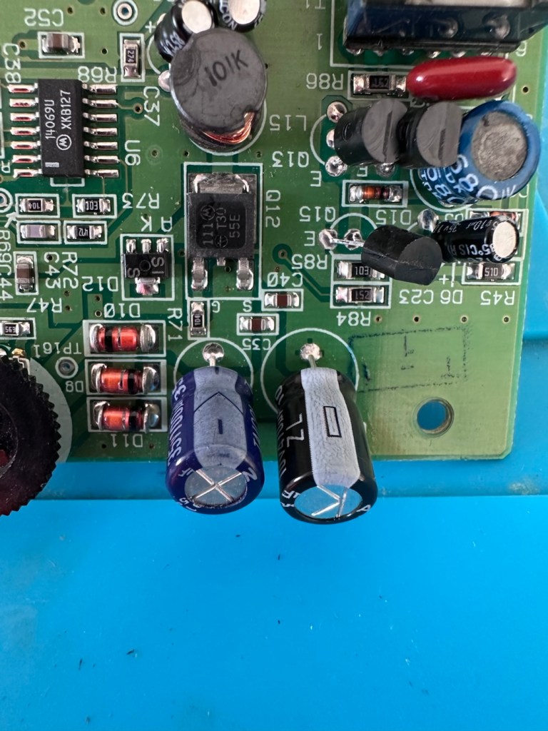
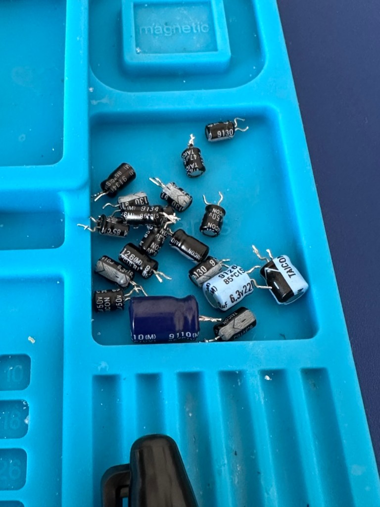
I’m going to order a full replacement capacitor kit, for an item of this age it’s probably a wise investment if you want the unit to be around for a good few years yet, even if the caps are not at issue they would probably need doing in the end anyway. The capacitor kit in its entirety (number of caps*) costs £9:80GBP and that’s a really reasonable price to pay to ensure the units usage can continue for many years to come.

The capacitor kit has arrived and there are 24 included. I think there are only 20 to replace (I could be wrong) so I may have a few left over.

The capacitor kit

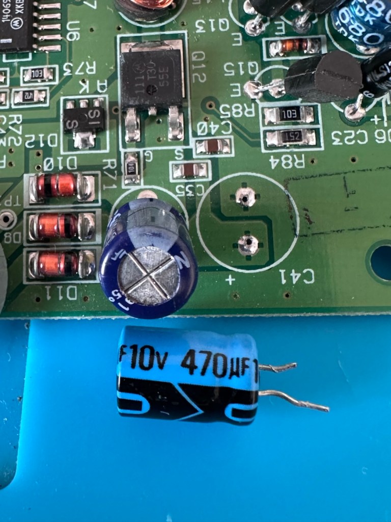
I’ve started by removing the most prominent known capacitor that falls and that is C41. It’s a 10v 470uF value and has a tolerance of +\- 20%. So in Theory this capacitor has a value that can fluctuate between 376 and 564 micro farad, and the one on this board is registering 514uF. In theory it is still working, however it’s gradually creeping closer to to the limits of its tolerance.

And to be honest, that was pretty much the same result with the other 19 I replaced. All were within their tolerance but at the higher end. The problem here is not capacitor related, however it’s always a wise move to replace them, before they finally go bad and cause other issues.

The recap has been successful, however I know it’s not going to make a difference, and putting it back on power confirms this. There is no difference to what I was experiencing when I first tested the unit.

No change

Annoying though this is, it is a job that needed doing and I’m now going to have to focus my attention elsewhere. I’ve checked the polarity of all the capacitors and I’m confident they are installed correctly and in the right positions. There are a few tests and checks to yet carry out, I’ll just have to do a bit of investigating to take this repair further.

These boards and their components such as the main chips and ram were developed to work with a power of 5 volts. However the problem here is that the supply via batteries or via an external power supply is 9 volts. Here lies the issue. On these units the power suppression part of the circuit, those components that filter and lower the voltage from 9v to 5v were known to fail, and when they did they failed quite spectacularly. With no protection built in to stop a surge of power, if some did fail, the full 9v would be supplied to most sensitive components rendering them beyond useless, and non repairable unless you have another donor board. Worst case scenario here is that the main CPUs of which there are two, could both be dead. In which case I may have purchased an expensive paperweight! But hey, let’s not go there just yet as there are a number of things we can do to check.

Next thing I have been doing is testing voltages around the board, and they are a little erratic to say the least. It is pointing towards the power board having its usual known issues. I’ve bypassed the power circuit to run a pure 5v through capacitor C14, same outcome here, this disappointed me as I was hopeful the game would kick in, it’s looking more like one of the chips have blown, the further I investigate.

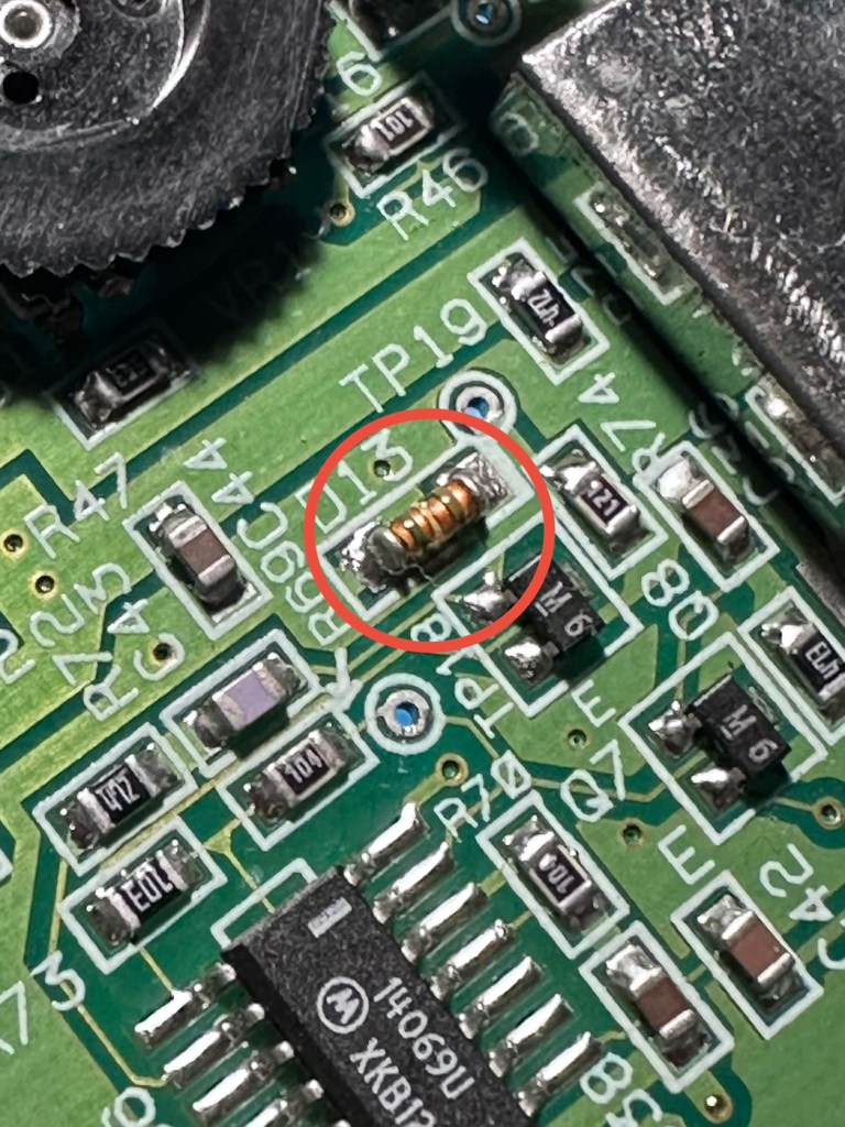
I have done a bit more testing around the power components and I have definitely found an issue with a diode D13, it’s letting power through in both directions and this is not right. I suspect there are more affected components in this area so I’m just going to go ahead and purchase a complete pack of replacement components for those known and prone to fail, on the power circuit. This will cost me £6:79GBP, another cost to add to this project.

I’m not hopeful though. Current testing results are all pointing to something more terminal. We will persevere for the short term though.

The parts required for the power board refresh have arrived.

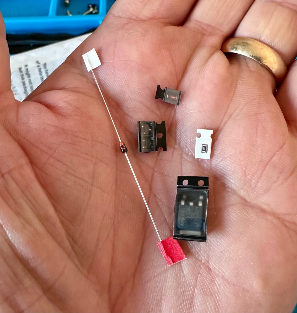
6 of the tiniest replacement parts

And they are minute in size. Installing these components is going to require a lot of patience and concentration.

The company that sell this power board refresh kit in the UK is ZedLabz.com and this is what their accompanying paperwork states:

Within this kit you will find a replacement Mosfet, two transistors, a resistor and two zenner diodes of different mounting types.

Part locations:

Q11 – Mosfet

Q4 & Q13 – Transistors

ZD1 – Zenner diode (two mounting types included)

R56 – Resistor 30ohm

This parts kit can be used on an Atari Lynx 1 or 2 handheld. One surface mount SMD and one axial through hole zenner diode are included, making it suited to both Atari Lynx 1 & 2, you can choose which type of diode you want to fit.

The kit also includes a resistor which can help with some models to push up the voltage enough to get it stable.

The parts we supply in this kit are from Major distrbutors only ensuring they are genuine.

Console dissasembly and internal soldering required.

ZedLabz.com

No kidding there! It should really say some soldering of components slightly smaller than a grain of rice is required. Let’s stop the whining and just get on with it.

I have replaced all of the five components that needed to be replaced, I’m really quite pleased with the job I have done considering just how tiny these components are, my soldering skills appear to have improved somewhat as a year or so ago I wouldn’t have even attempted such a job. That’s the positive.

But now the negative.

It’s Dead, very dead.

There is still no improvement despite pretty much an entire rebuild of the circuit. I have checked all voltages and they are in the right place showing the correct values. It’s been recapped, the power board has been rebuilt, all solder joints have been checked and ribbon cable connections have all been reflowed.

Result:

My conclusion that the previous owner was well aware of the issues, they probably contributed to the problem and the unit has been sold on as “spares and repair only”. I have failed to pay attention to the old Latin saying “Caveat Emptor” or buyer beware.

The situation is this. A new LCD screen can be purchased to drag the unit into the 21st century, but there is no point when we have no sound and vision being produced. The problem here is that the 9v power supply has already been able to get to the delicate parts of the circuitry where only 5v should be in attendance. I am 99.9% certain that the ram chips as well as the two logic chips “Mikey & Suzy” have long departed. And there lies the problem. The two logic chips are as rare as hens teeth and are pretty much only available when transplanted from a donor unit. The unit is basically dead, it’s just a paperweight.

I will put the unit into storage until a later date, when I have done a lot more research and who knows I may even find a suitable donor board to transplant those two logic chips.

For now the project is on hold. I don’t like writing of failures as many hours of work over many weeks has been dedicated to this project. You can’t win them all though, and some you just have to step away from a project to get a fresh aspect on it. Having this log of activity is fantastic for me though as it will now become the reference for where I go next.

It’s a learning curve, that’s for sure.

When I come back to the project I will obviously link to this post.

Thanks for passing by. It’s always very much appreciated.
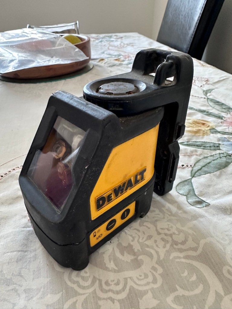
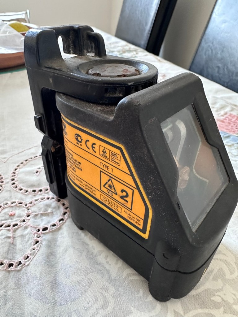
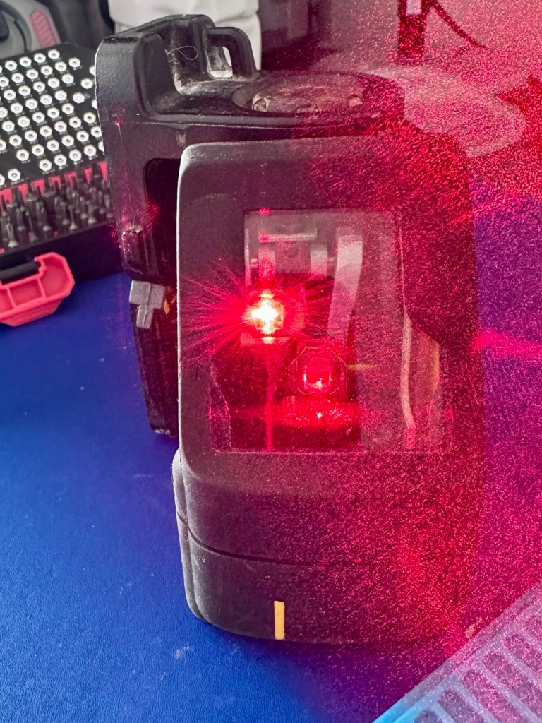
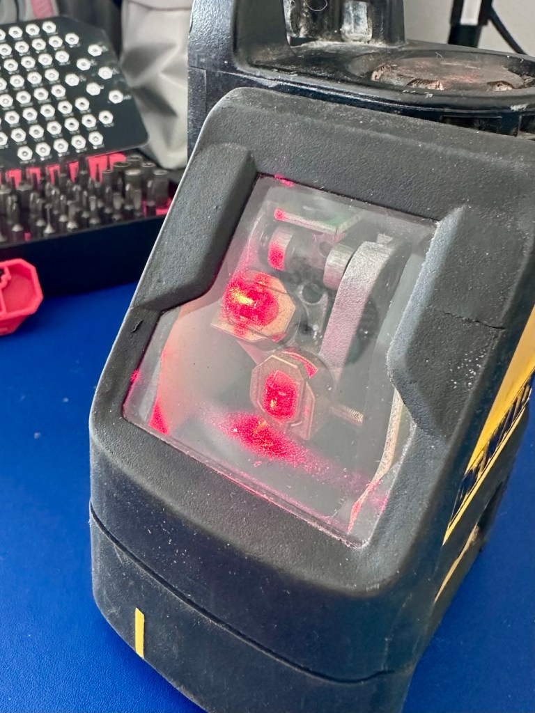
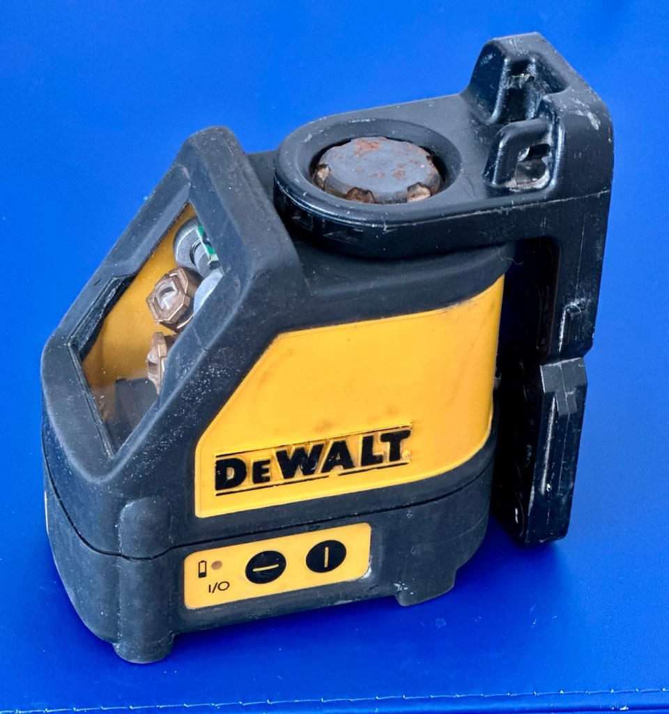
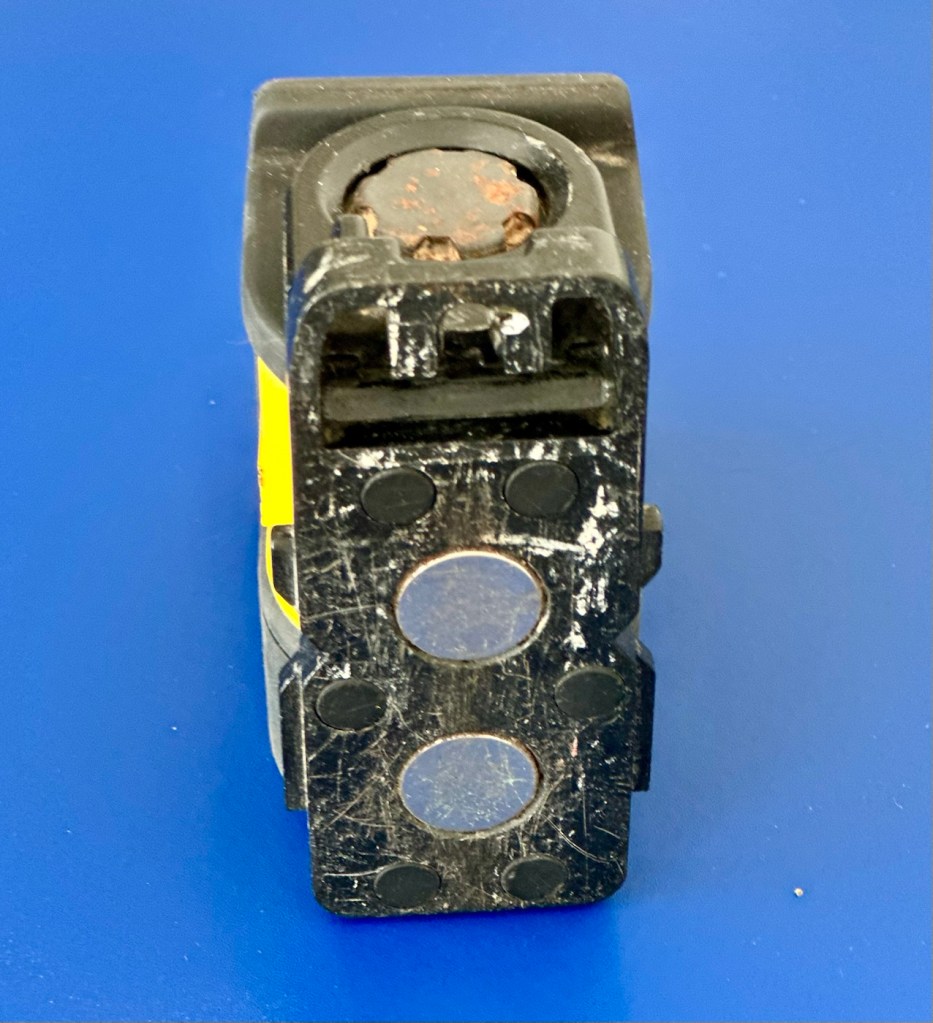
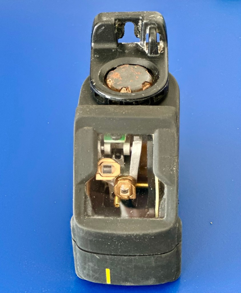
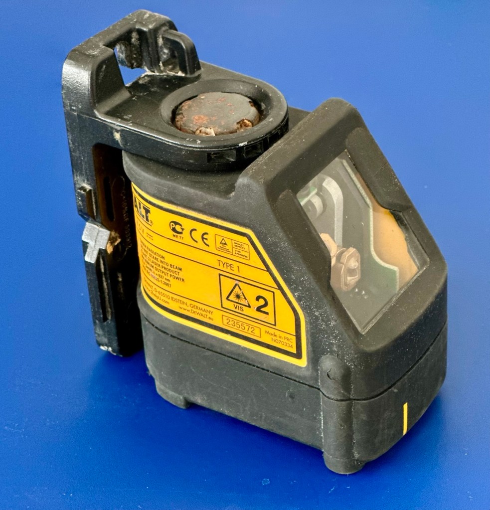
Dewalt DW087 Self-Levelling Cross Line Laser

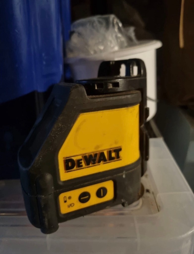
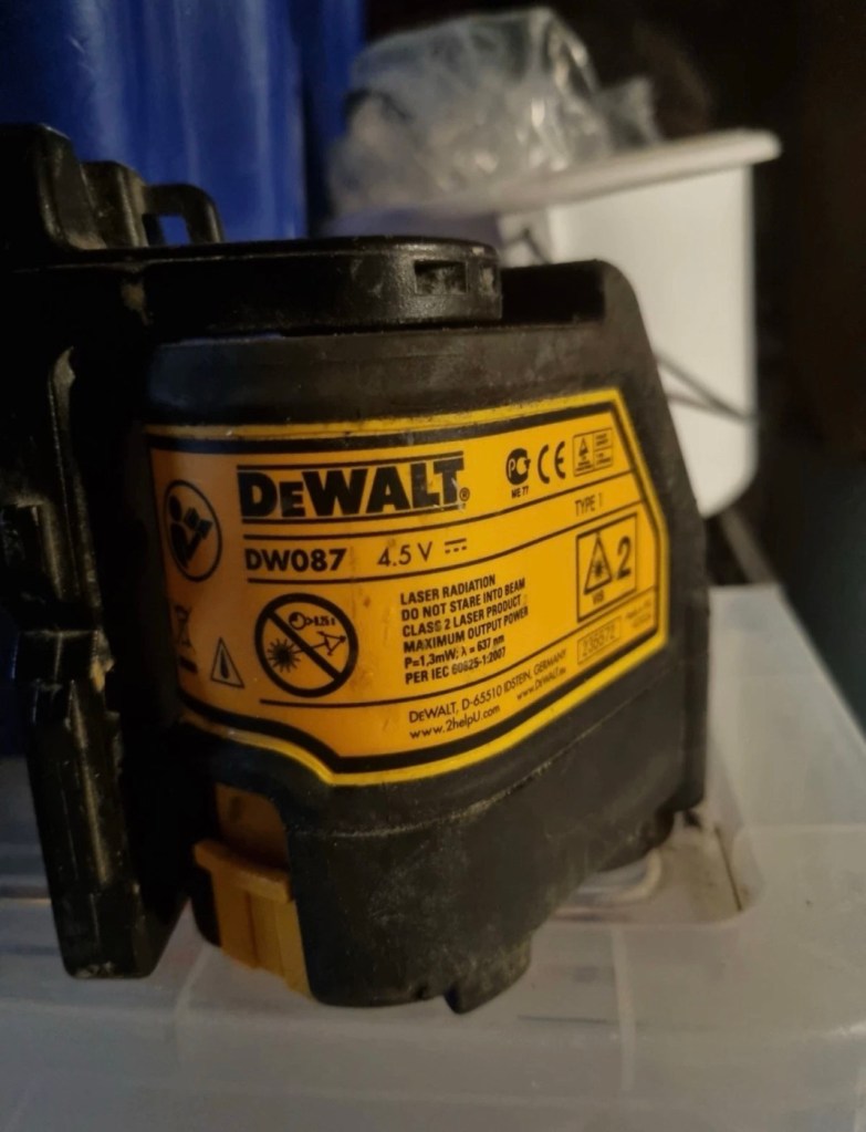
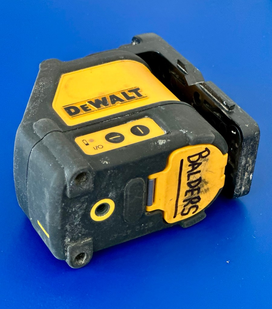
Just picked up a badly damaged Dewalt laser levelling unit. Old and damaged, can I bring it back to being useful again? I can only try.

What the listing stated:

think the batteries melted in the chamber. does not work at all.

EBay

Straight to the point, the words “severely knackered” I think, would probably be a more appropriate quote, however I must be patient and await its arrival.

When working and from new, these little laser levelling units retailed for approximately £175:00GBP. However they are of the older red laser model and new units use a green laser, so the older red laser version is now out of production, but still well sought after on second hand markets where it can still command prices in the £50-60:00GBP range. I’ve paid the princely sum of £6:00GBP for this one, so I’m very happy with that. If I can get it working it will go into my own tool kit for use.

Here’s a little about this unit:

A new DeWalt DW087 (or the DW087K kit) generally retails for around £178 to £185. However, because this specific model is an older red-beam line laser, used or refurbished units are widely available across secondary markets, typically ranging from £50 to £80 depending on condition.

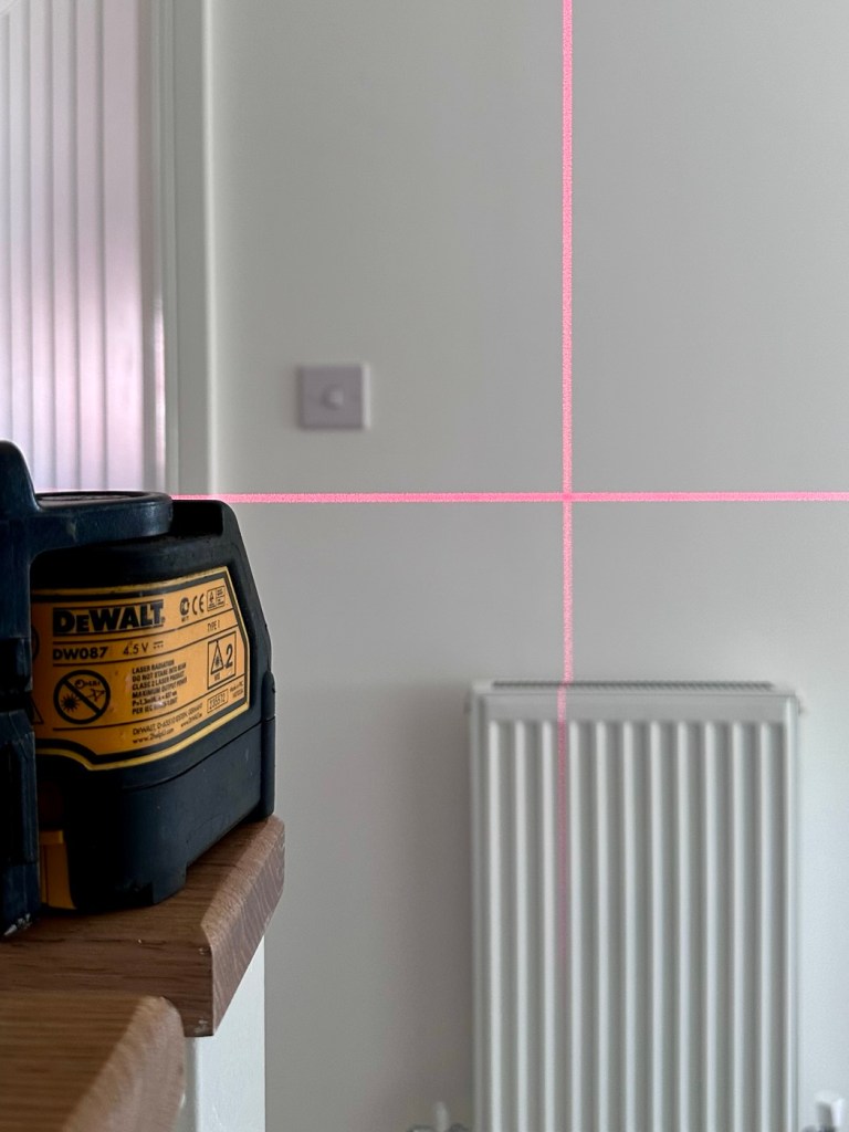
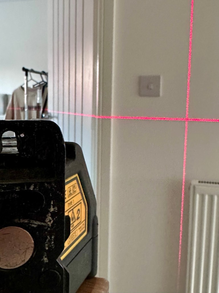
The DeWalt DW087 (often sold as the DW087K) is a self-leveling cross-line red laser. It projects bright horizontal and vertical lines with an accuracy of ±0.3 mm/m and features an indoor visibility range of up to 15 meters. Powered by 3 AA batteries, it includes a built-in magnetic pivot bracket for quick metal mounting.

So. Basically it used by tradesmen and women to set up a visual laser projection around an area. Just think about putting up kitchen cabinets or worktops, and you’ve probably witnessed one of these in action. The one I have purchased sounds as if it is in a pretty poor condition, the lack of pictures showing the battery area speaks volumes and is probably hiding a crime scene, however I’ll just have to wait and see.

Assessment:

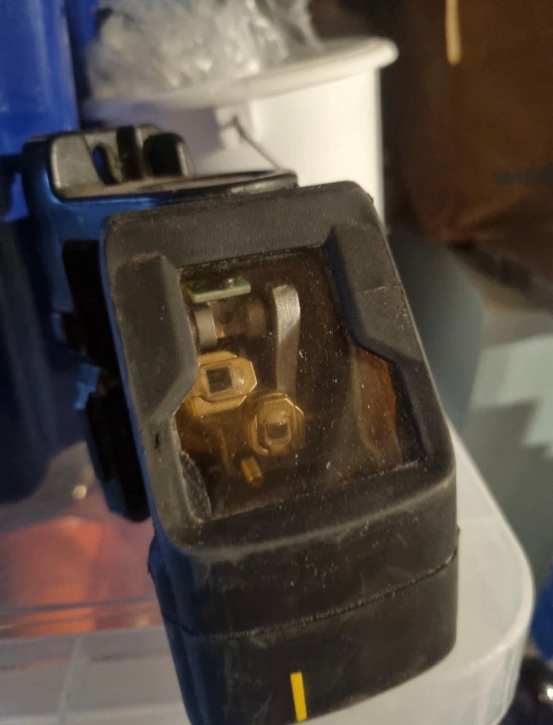
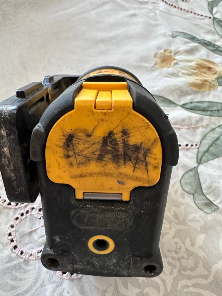
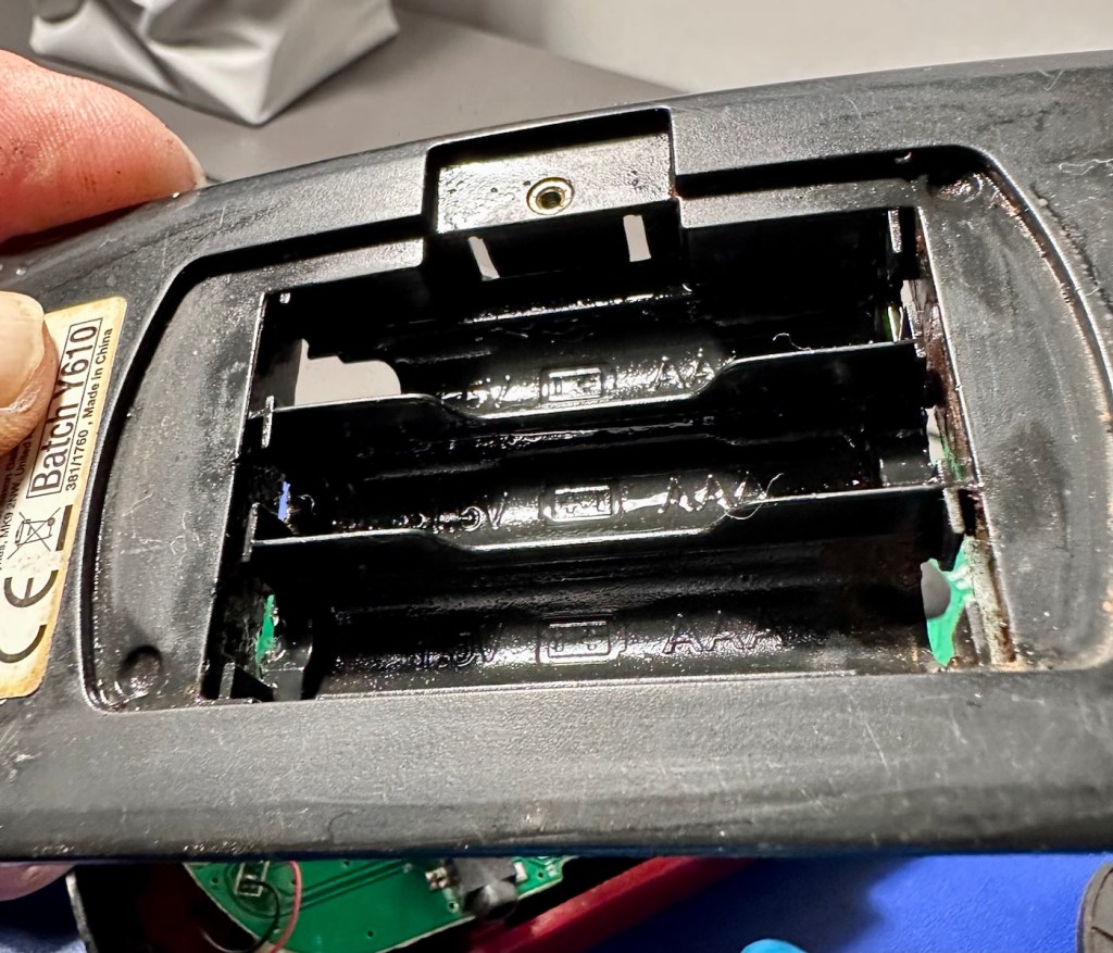
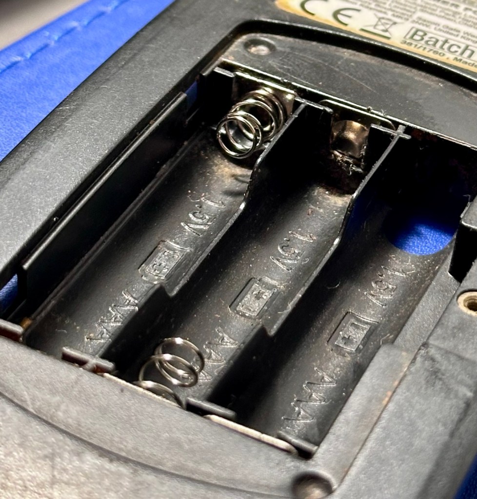
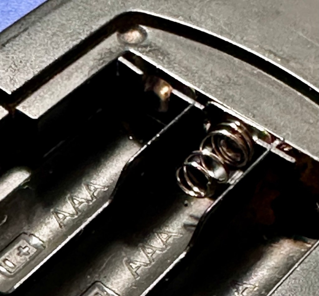
It has arrived. It’s as expected, looks like it’s been around a few building sites and most definitely does not work. The good thing is that the description of the batteries melting in the chamber was not so, in all truth it appears they have corroded the contacts a little, and one point of contact required to complete the circuitry appears to be broken.

It’s dirty no doubt about that, but it can always be cleaned.

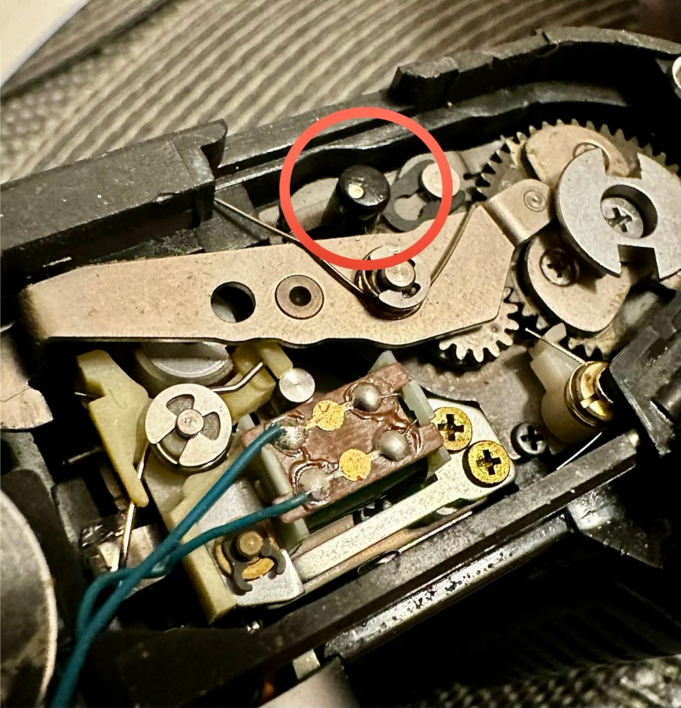
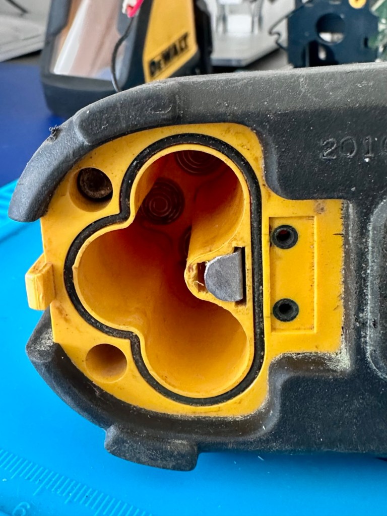
The missing contact

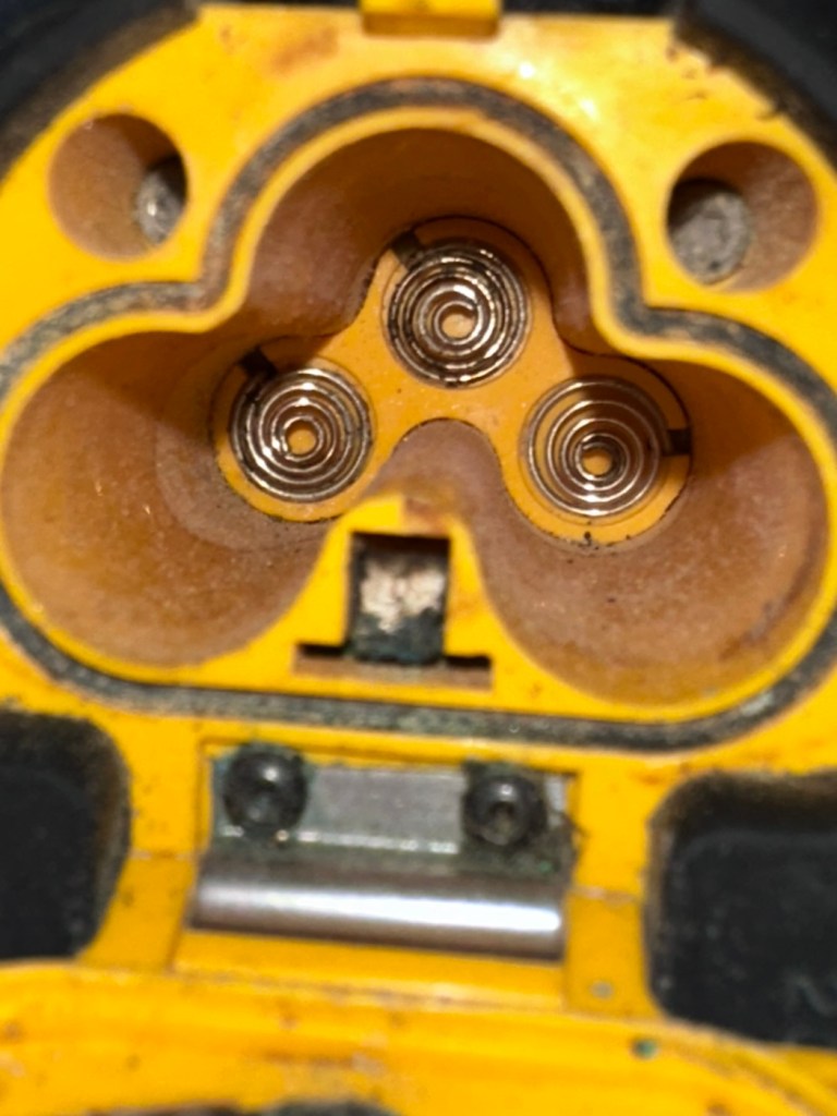
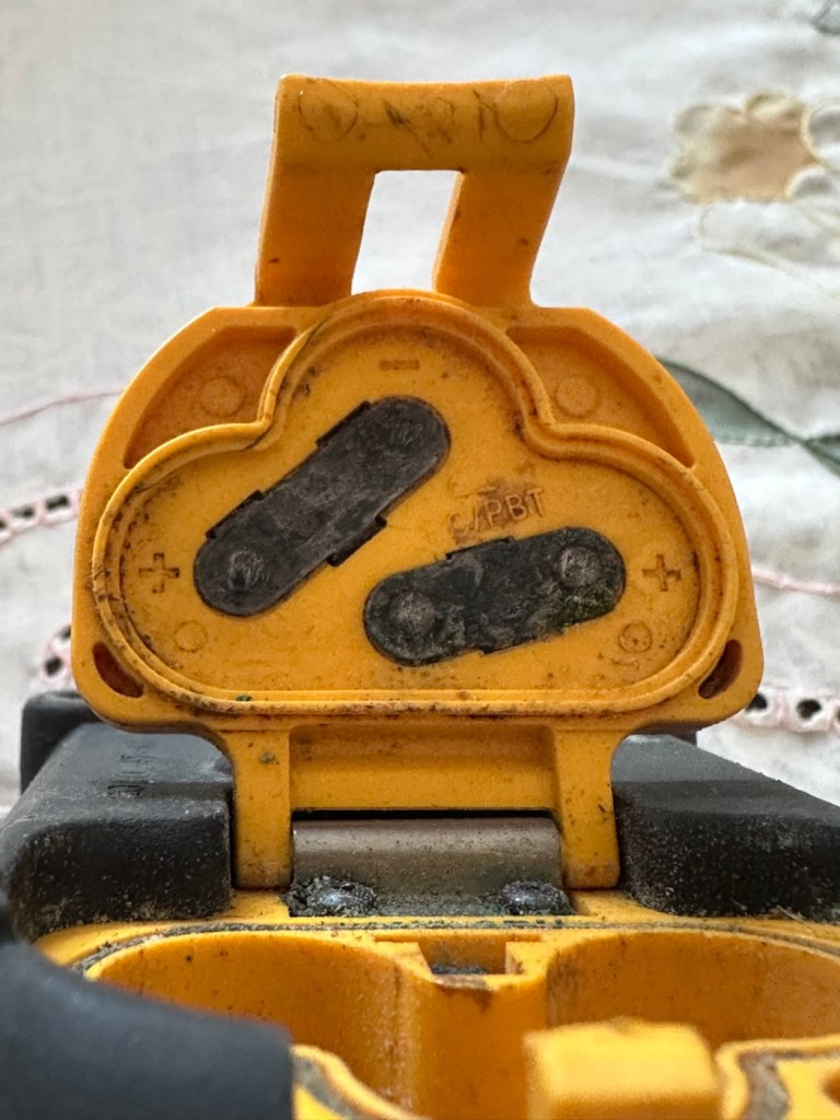
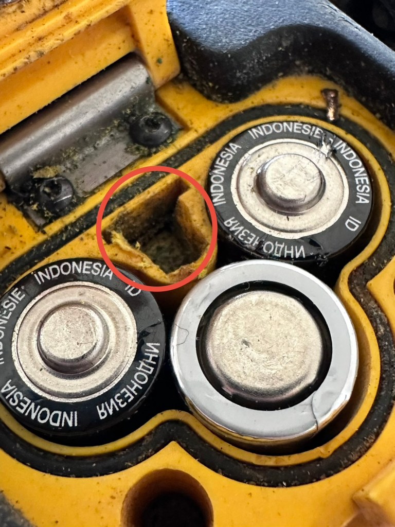
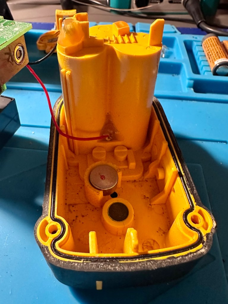
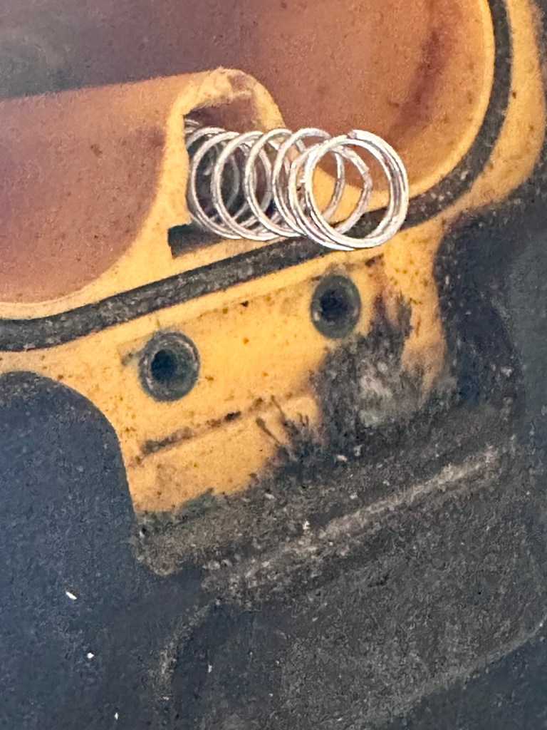
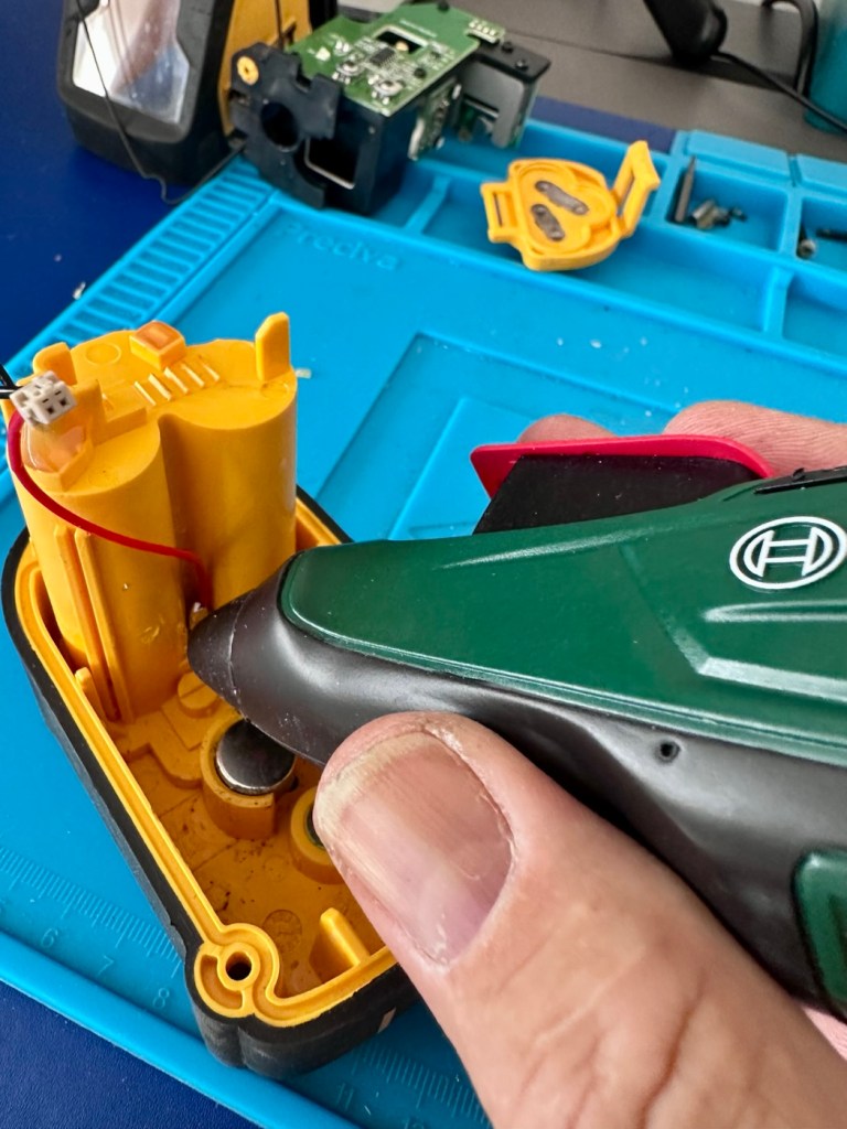
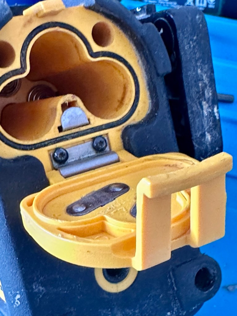
There is a missing contact as highlighted in red, in the picture above. This connects with the battery contacts in the battery lid. When a circuit is made the level will work. There is a small piece of metal strip at the base of this hole, the remnants of the contact that should be there. I have managed to get the unit working by temporarily putting a small spring in here to bridge the contact. This will have to be replaced or repaired though.

Repair:

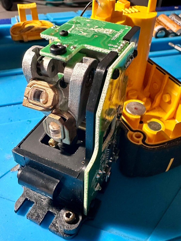
The first thing to do is to get the unit disassembled, and that is surprisingly easier than I thought. Four screws later and the body can be pulled apart. Another two screws removes the battery flap. Easy.

There are a couple of rubber gaskets that fit in between the two parts to ensure an airtight seal and to stop the ingress of dirt. I have given the lenses a clean with a camera lens cloth, I have cleaned both inside and out of the window and given a good blow through with some compressed air. I have used a multimeter on the power led in diode mode just to check that it is operational, and it is. There is nothing else needing attention within the internals.

Turning my attention to the battery chamber and battery lid I give both a thorough clean, the negative terminals in the battery chamber are cleaned with an IPA solution to improve their appearance, the whole chamber is cleaned in the same manner and is looking good.

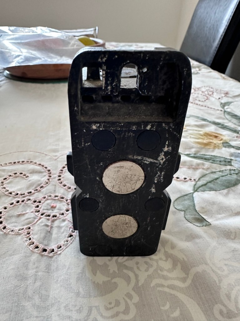
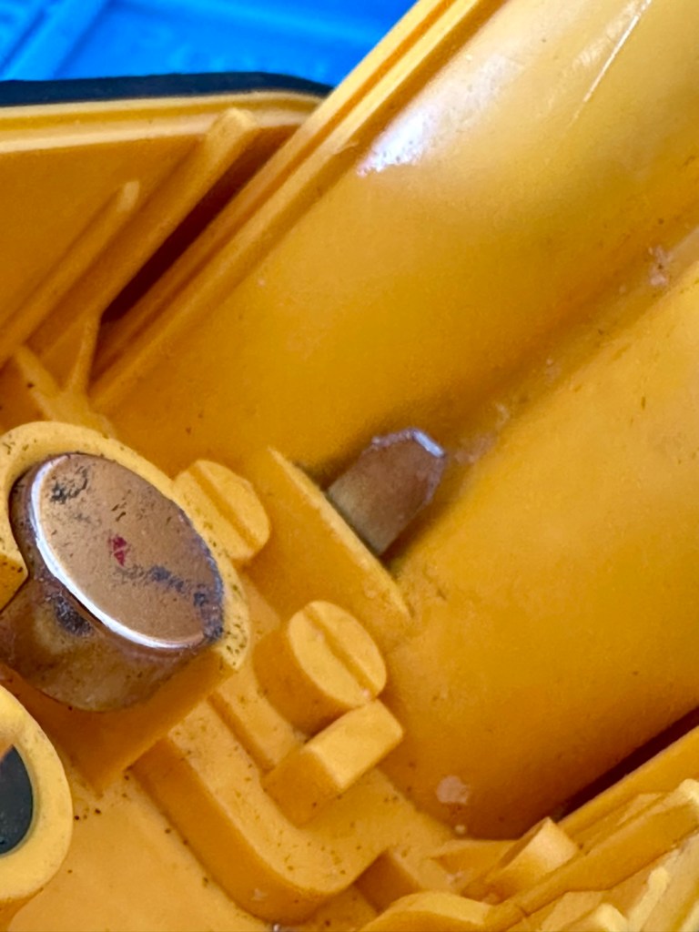
There was a collection of what appeared to be iron filings where the battery lid joins the body, and this is because on the opposite of this point, there is one of two strong magnets that keep the lasers level. Holding the unit over a bin and lifting the magnet out ensured a nice little rainfall of iron filings into the bin and not all over my workspace. With the magnet now replaced I gave this same area a further good clean with IPA.

The battery lid has been left to bathe in a dish of white vinegar to help remove the remainder of the tarnishing to the battery contacts attached to it. It’s worked ok, a final tidy with a grinding pen has brought this up well, looking a lot better than it previously looked.

I now need to look at that broken contact.

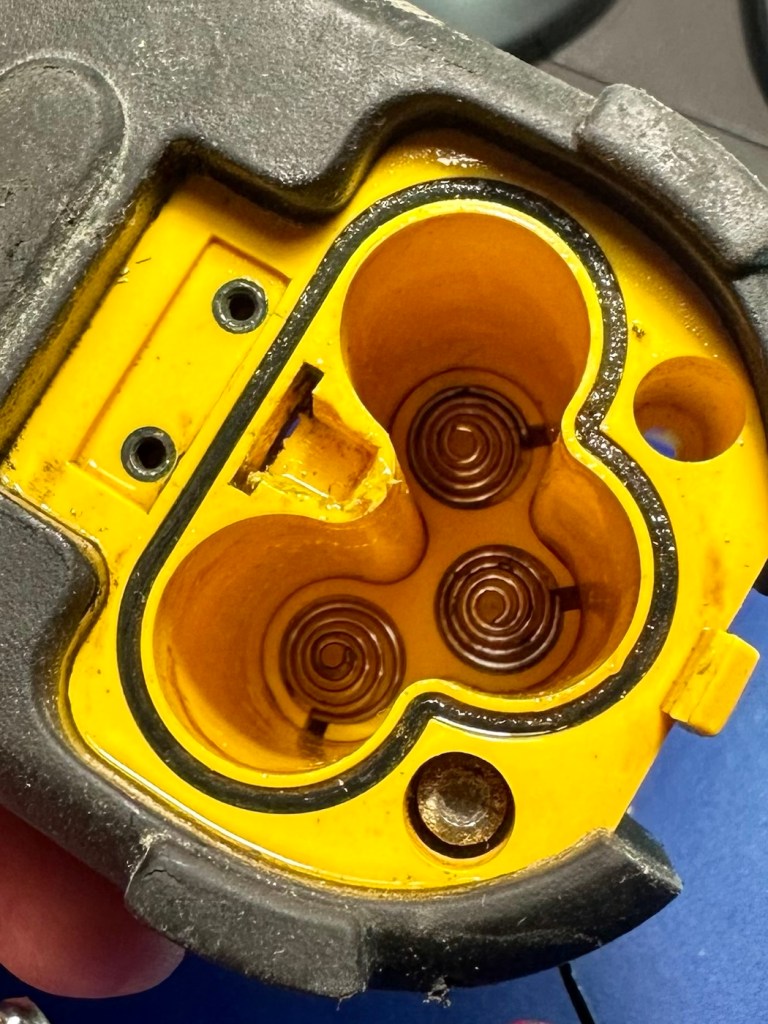
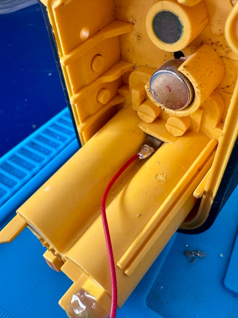
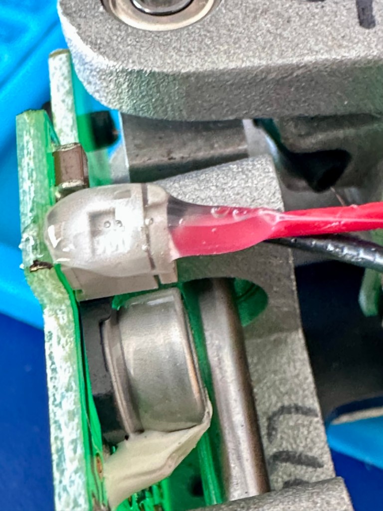
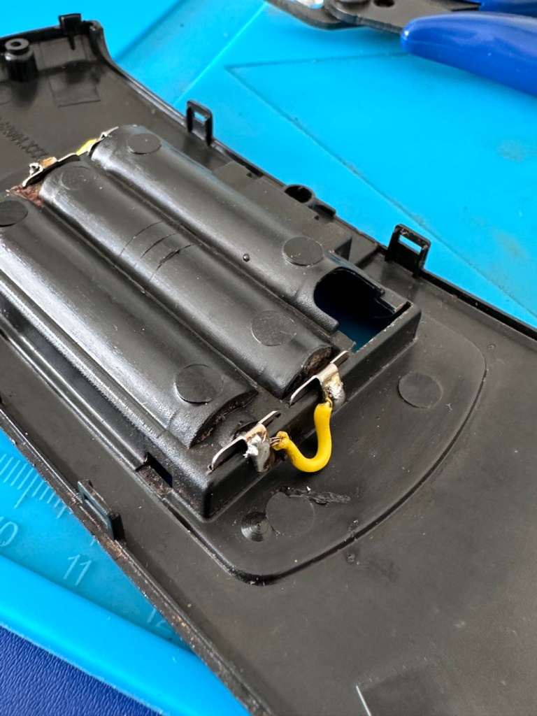
The wiring for the contact has been hot glued into place on the reverse of the battery chamber. I used some IPA to loosen the old glue and that allows me to remove the remainder of the broken contact. The top part missing from the inside of the chamber has long gone. I will have to fabricate a replacement myself. The wiring you see above was also hot glued to a plug on the main circuit board. Again, an application of IPA softened the glue and I was able to remove the plug from the circuit board to be able to work freely on the battery chamber. When the work is complete I will re glue both these items back into place prior to reassembly.

I’ve formed a small contact out of a piece of pliable metal to use in the device.

It fits nicely and is cut in such a way that it won’t push through into the chamber when a slight pressure is applied. I’ve hot glued both surfaces that I had removed glue from in the first place to gain access. Now the unit is being reassembled they’ve been glued just as they were previously.

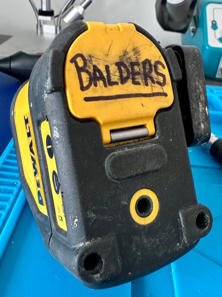
Now the unit is back in one piece it’s now time to reattach the battery chamber lid, and in time honoured tradition, I’ve daubed my nick name on the lid, as this will now go into my toolbox in my garage.

Now all that is left to do is switch it on.

And it works just fine….

Let’s now just give it a practical clean, it’s a working item for rugged situations so it isn’t going to look “Shop” new. But it will be an awful lot cleaner.

Result:

A tool that originally retailed for £175:00GBP and available on the auction sites, in good working order of between £60-£90:00GBP was purchased, non operational for the grand total of £6:00GBP. If that isn’t a bargain then I don’t know what is.

For little more than a couple of hours work I now have a valuable practical item to add to my toolbox because someone else just couldn’t be bothered to spend the time on it to get it working. Lucky me.

Definitely another item saved from landfill, with a new lease of life that should go on for many more years yet.

I’m very happy with it, this was a pleasure to work on.

Many thanks for passing by, as always it is very much appreciated.

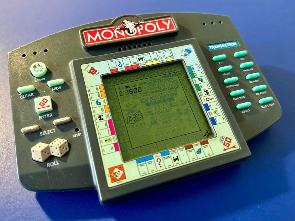
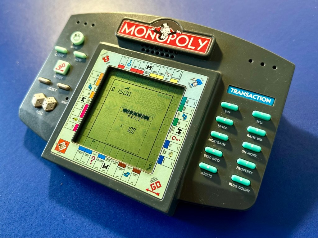
MONOPOLY ELECTRONIC HANDHELD GAME

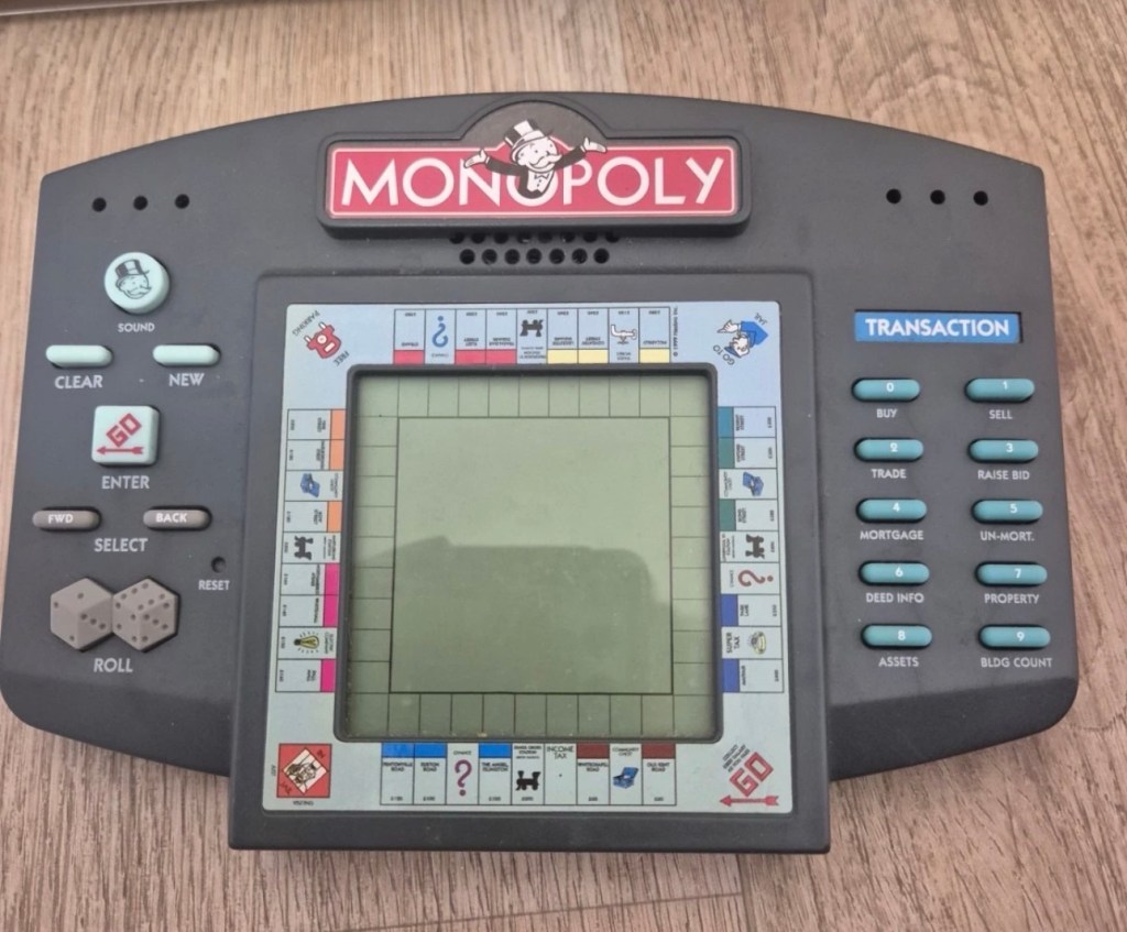
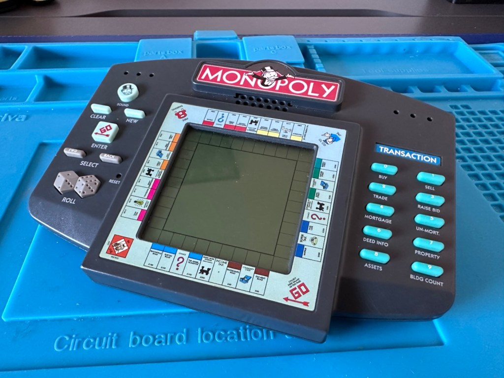
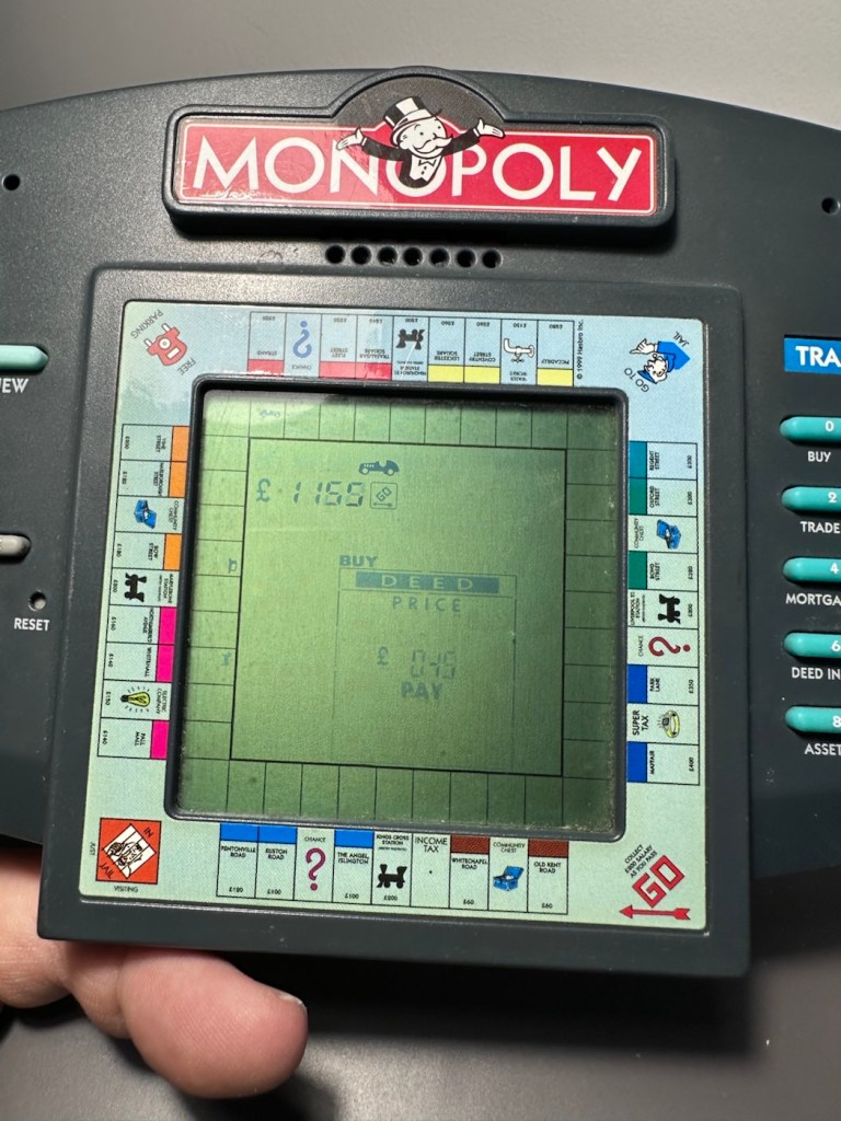
A dead Monopoly electronic handheld game from 1999. Can we resurrect rich Uncle Moneybags?

What the listing stated:

The Vintage Monopoly Electronic Handheld Game from Hasbro (1999) is a classic electronic game that allows players to enjoy the iconic Monopoly game on the go. With its handheld design, this game is suitable for players aged 4 years and above, making it a fun and engaging activity for children and adults alike. Although untested, this nostalgic piece of gaming history is sure to bring hours of entertainment to anyone who enjoys the challenge of a good game of Monopoly.

EBay.

The item I have purchased

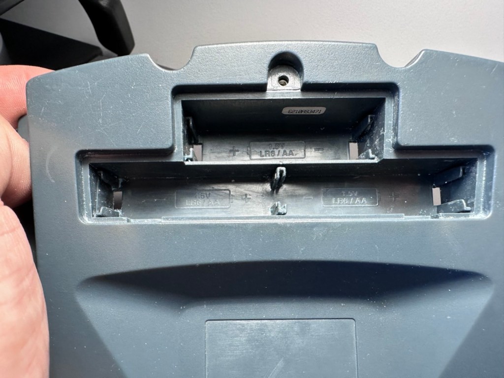
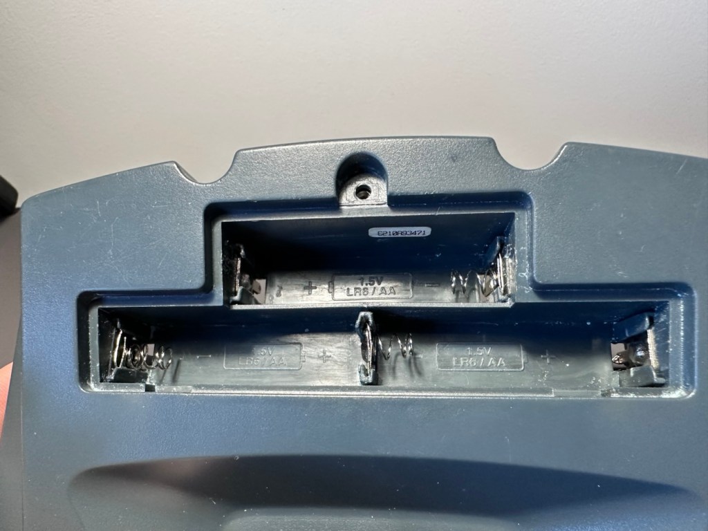
The good old EBay get out of jail free card (How appropriate 😂) of untested. This item takes three AA type batteries, just what does it take to pop three battery in and turn on the unit. Why am I so sceptical about this item? I just have a feeling that it’s going to be riddled with issues and I bet one of them involves battery acid.

But, miracles do some times occur, so let’s just await its arrival so I can carry out a full assessment, in the meantime here is a little bit about this game.

The 1999 Hasbro Monopoly Handheld game is a classic electronic version of the board game designed for solo or multi-player action. It features computer-controlled opponents, a virtual LCD board, and an interactive narrator (Rich Uncle Pennybags) who guides you through buying, trading, and auctioning properties.

Gameplay Features

The 1999 handheld faithfully recreated the full experience of the classic board game in a portable format. Key highlights include: 

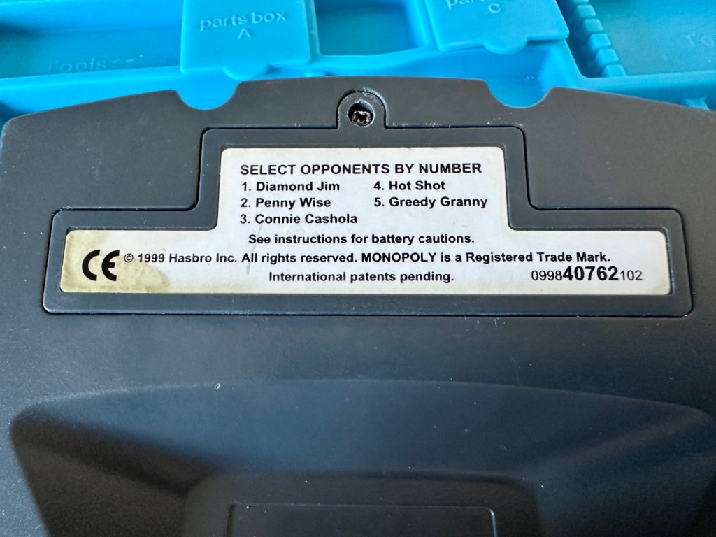
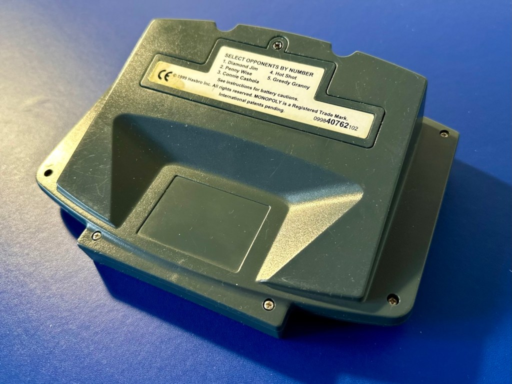
  • Computer Opponents: Play against up to 3 to 5 distinct, computer-controlled characters (like Diamond Jim or Greedy Granny), all of which operate at different skill levels.
  • Full Board Mechanics: You can buy, sell, mortgage, trade, and even auction off properties.
  • Audio & Visuals: Features a custom LCD display, physical buttons for menu inputs, and fun real-sound effects.
  • Power Requirements: The unit typically requires 3 AA batteries to operate. 

T’internet

Assessment:

Well, my suspicions in this case are correct. It has arrived and for a unit that is now 27 years old I must admit that cosmetically it is in a good looking condition, with all labels intact, minimal marking on the screen, and all buttons appear to be clicking. All body screws are present and do not appear to have been tampered with at anytime.

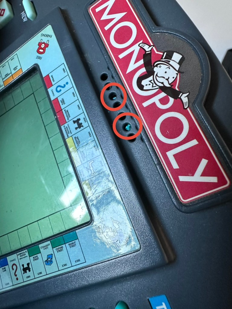
But hold on, what’s that I can see through the speaker grill on the front?

Battery contaminant viewed through the speaker grill.

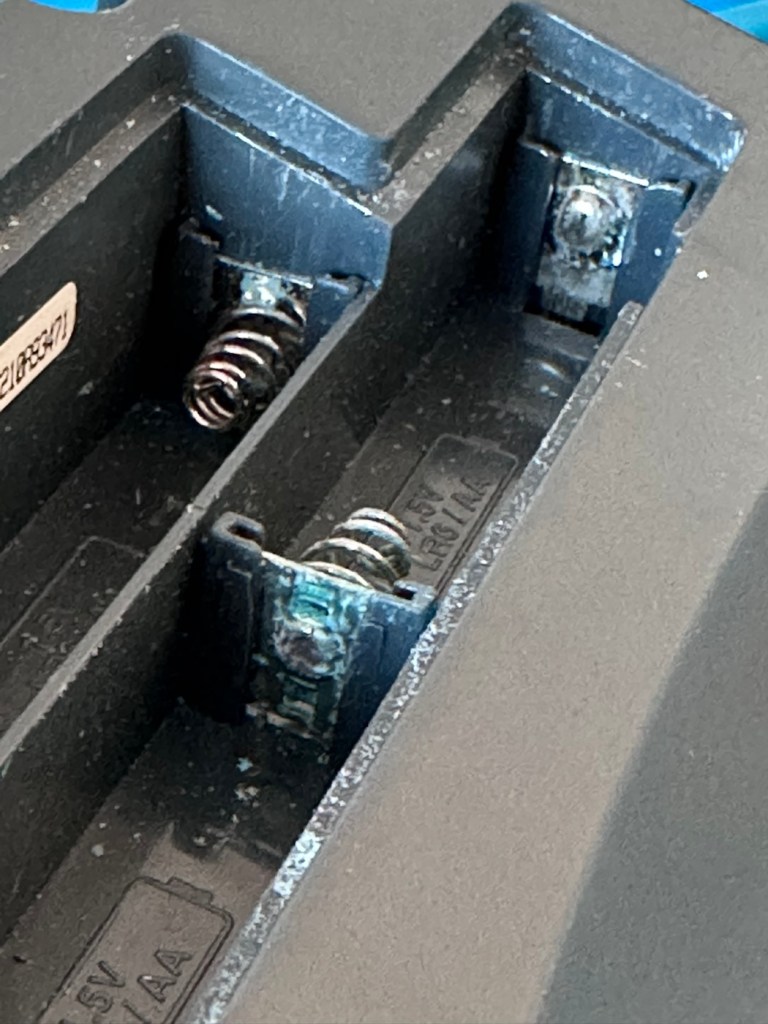
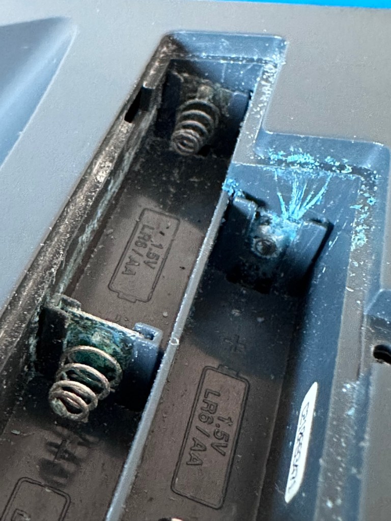
I open the battery company and as I previously thought there are signs of battery contamination.

Bugger. Ok I’ll put three batteries in but I’m pretty sure I know the outcome. Yep, it doesn’t power on. The unit is dead.

An untested unit. It’s taken me 30 seconds to test and confirm the issue. Wouldn’t have hurt to be honest and to have done the same would it?

I paid £7:90GBP for this unit, it was probably the least expensive of all those available at the time, I guess I can’t complain really, I just detest people’s deliberate dishonesty. Ok, whinge over let’s open up the unit to delve a little deeper.

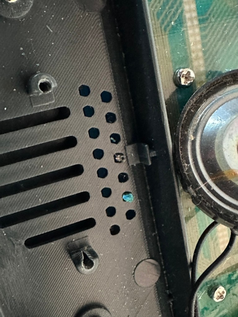
I open the case and can breath a slight sigh of relief. Yes there are obvious signs of battery contamination, but not as bad as previously thought. As I had seen signs of contamination in the external speaker grill, I’d thought the insides were rotten. In fact the contamination in the speaker grill was only a few grains of contamination that had broken away from the battery compartment.

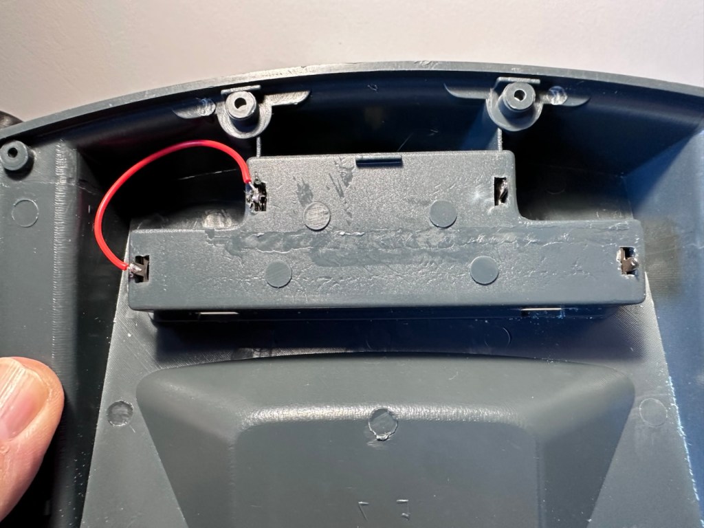
The wires near to the worst points of contamination in the battery compartment were pretty much rotted and covered in old battery acid. One jumper that would complete the continuity of the battery/power flow had rotted off and one of the very thin speaker cables was also broken.

Repair:

I’ve given the mainboard a good clean with IPA and set about removing all the battery connectors from the battery box.

I’ve reattached the jumper cable with some fresh wire, I’ve trimmed the rotted wires down to some good unaffected wire and reattached these to the new battery connectors. The speaker wires are freshly soldered back into place.

With everything now connected up I put three batteries in to place and can instantly hear the computers electronic voice welcoming me to Monopoly, Rich Uncle Moneybags lives again.

Time to reassemble the unit.

So the issue was here was the result of battery contamination. Four battery contacts, and one wire, were all that were additionally required along with a lot of cleaning and some re soldering to secure some weak connections. It’s now a complete working unit.

Result:

As usual, this would have been a prime target for the tip as it’s just one of those disposable units we have created as the wonderful guardians of this little planet we reside upon. It’s taken probably about 30 minutes of time to repair (and about the same to clean internally) to bring this unit back to life. A good polish externally and it’s now ready to be put back into use.

And my chief tester for these type of items is my wife who absolutely adores the game of Monopoly.

The only real issue with these units is that they never came with an on/off switch. You had to put the batteries in and then remove them when you were finished, this is very strange. However when you read up on line you can see that many people have made modifications to put volume controls (even though there is a three press button version built in) and on/off switches on the unit. I will probably put a switch in myself when I come across a suitable one to use.

In the meantime we now have a working unit, the wife gives it her nod of approval and that’s good for me.

A simple repair, very little outlay and only a little time was all that was required to save another item from landfill. Wouldn’t it be good if we could all take the time to repair rather than dispose.

Thanks for passing by, as always it’s always very much appreciated.
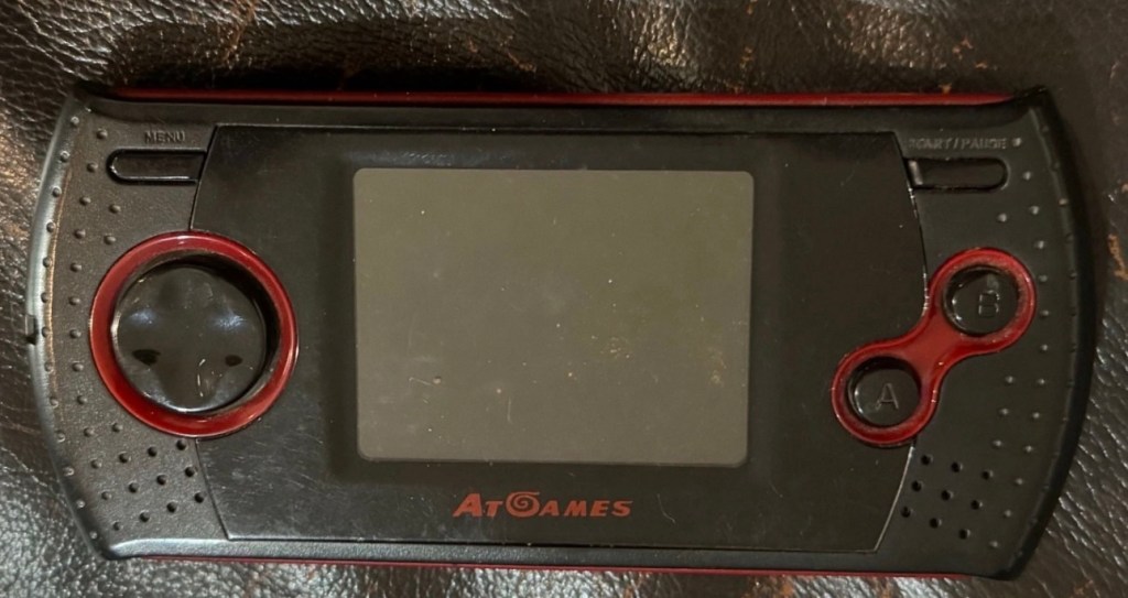
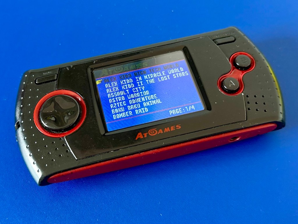
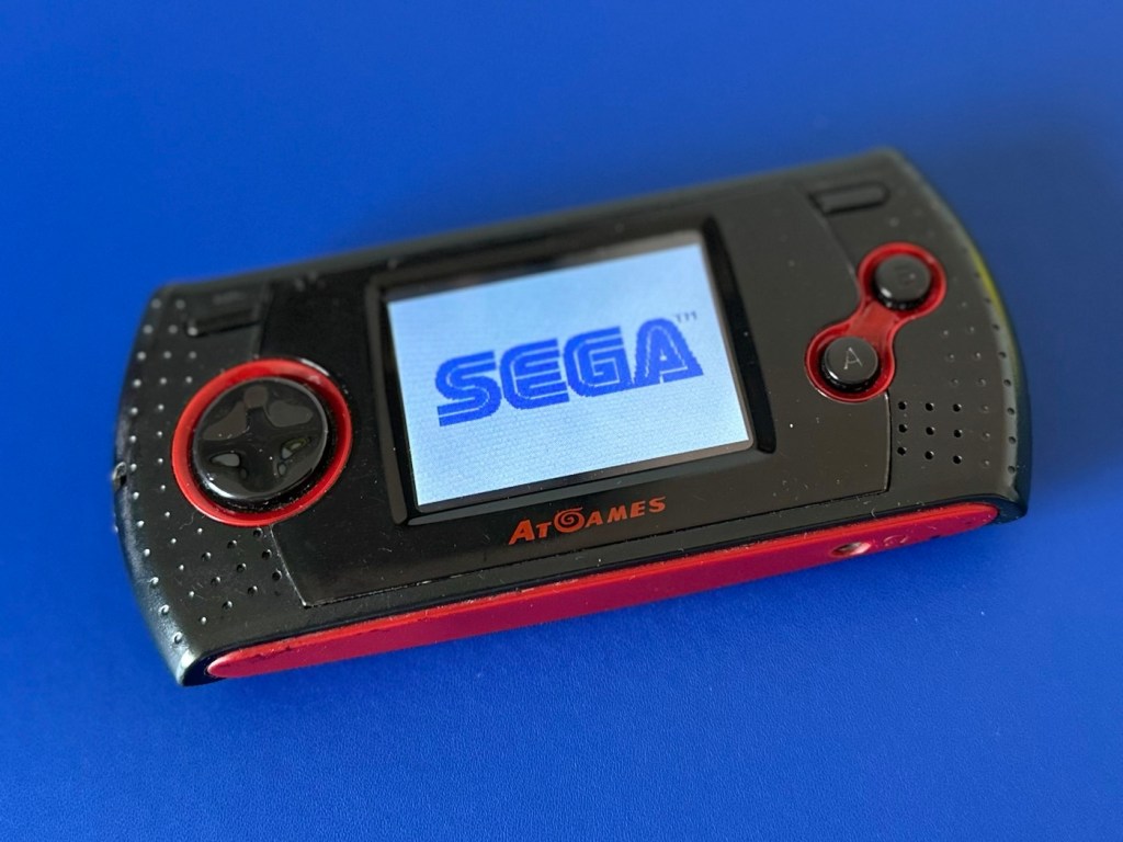
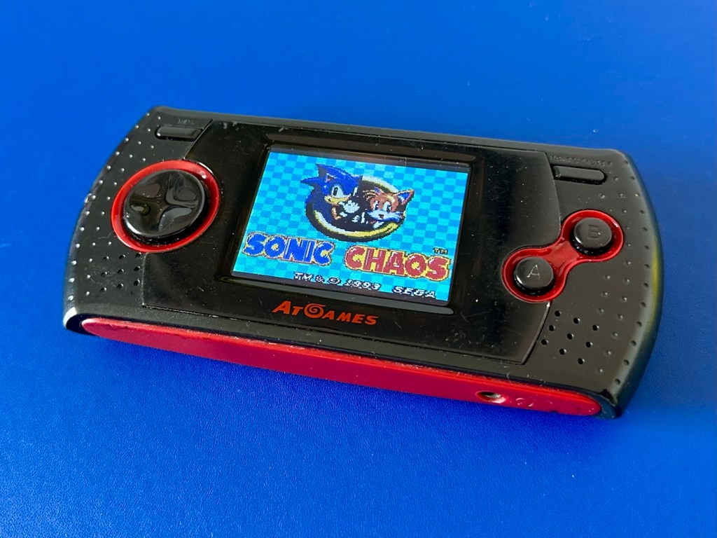
Sega Mega Drive AT Games Portable Arcade Gamer

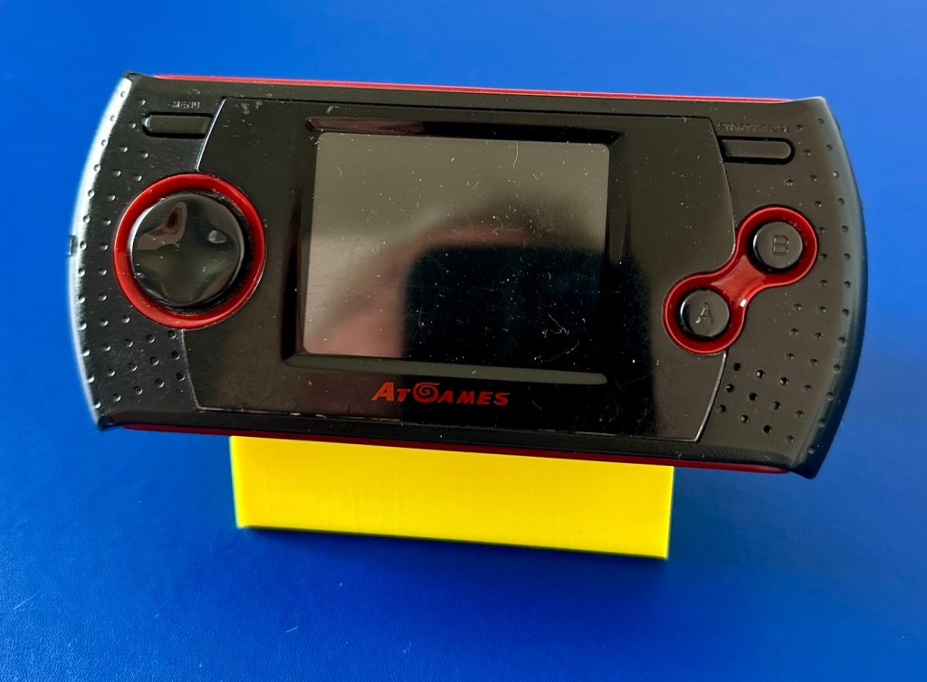
From 2008 this is an AT Games, Sega Megadrive portable games unit. It’s an emulator console that has seen better days. It needs a lot of attention. Let’s see what we can do.

What the listing stated:

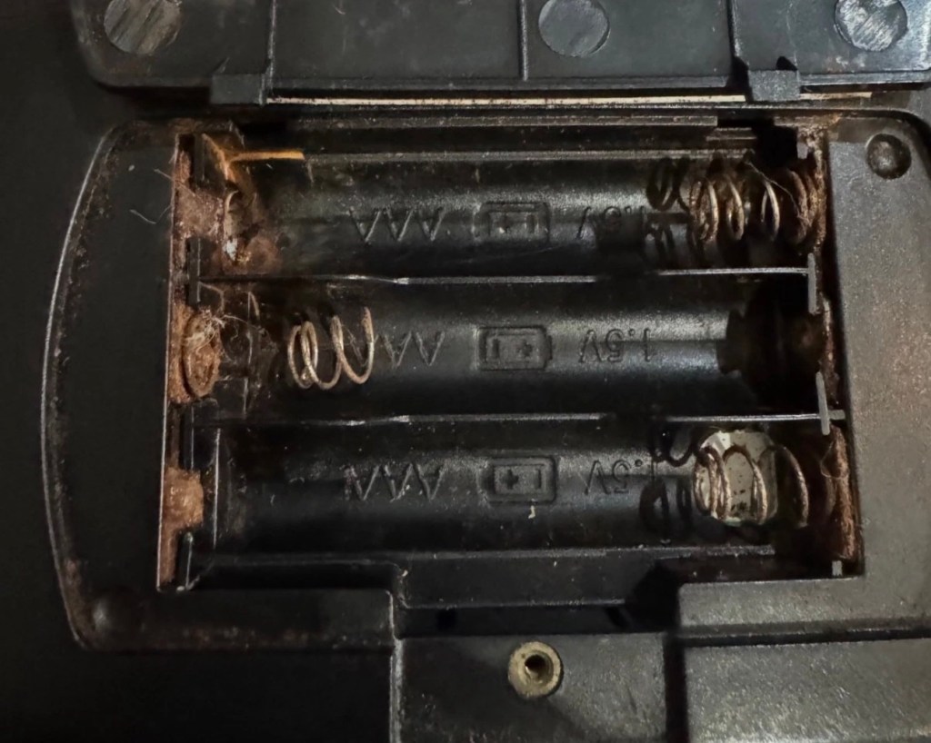
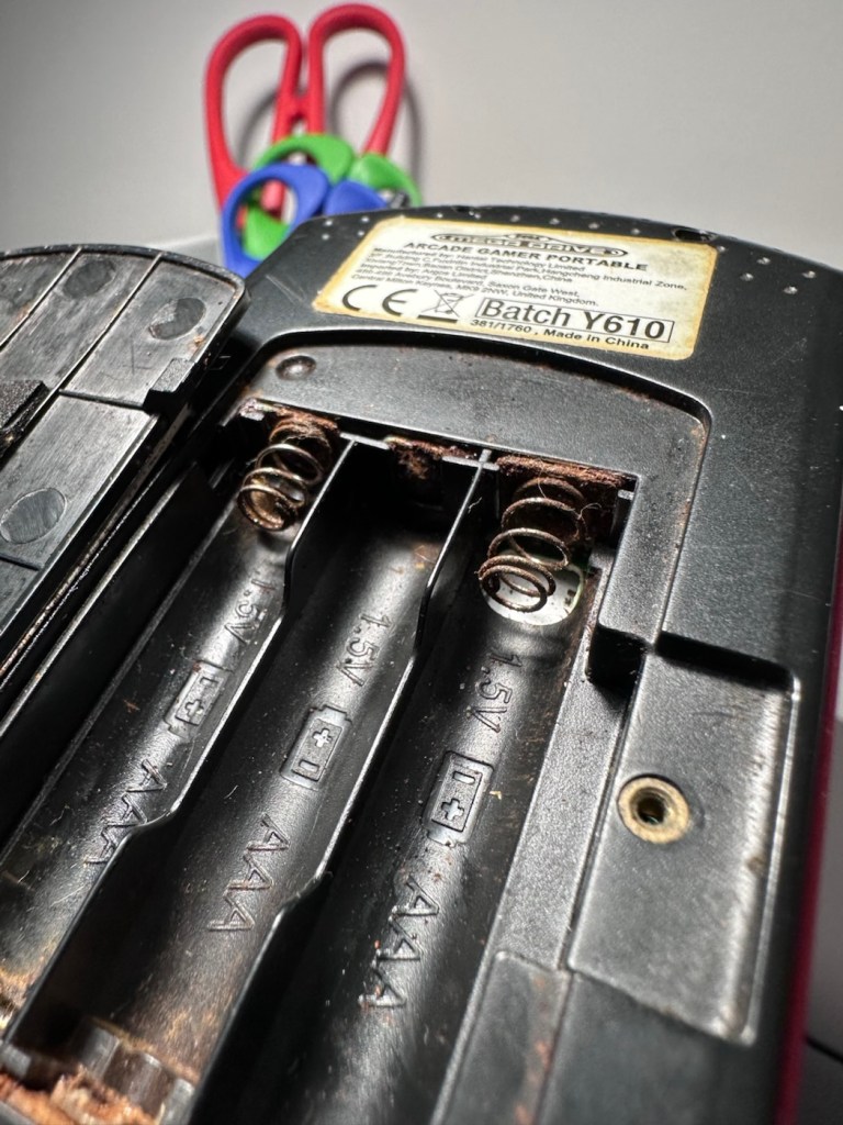
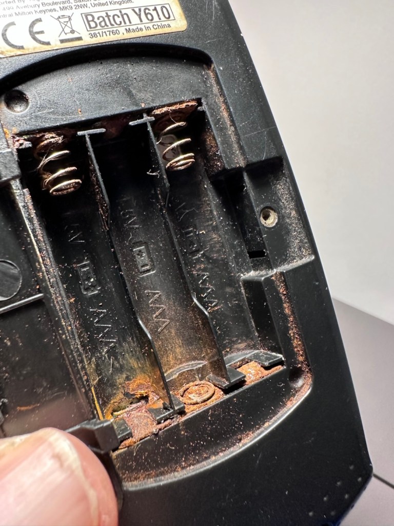
I can’t get the device to power on. This is possibly just due to corrosion (and one snapped spring) in the battery compartment. Someone more adept at fixing things may be able to bring it back to life but unfortunately I can’t so listing it as spare/repairs/faulty.

EBay

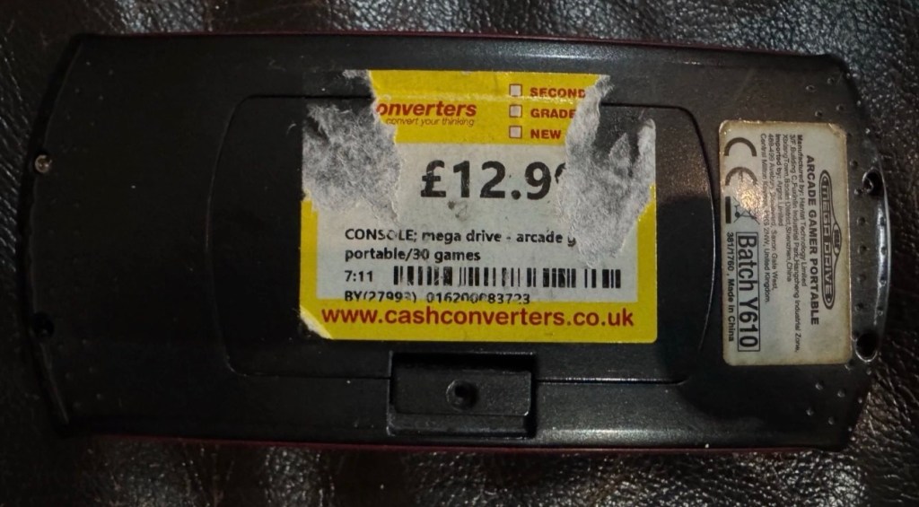
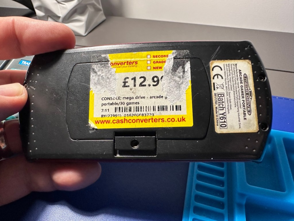
I sure as heck wasn’t going to pay the old price advertised when the previous owner obtained this from Cash converters.

Let’s just say I paid considerably less than the price tag on the rear of the unit.

These handhelds were sold as emulation devices usually preloaded with games, between 20-80 games were the norm, I believe this is a 30 game option, if the information that is left of the previous price tag is to be believed. They were originally sold within the UK by the national retailer – Argos, and it originally retailed at a price of £29:99GBP.

A little about these units:

The AtGames Arcade Gamer Portable is a licensed, handheld “console-on-a-chip” manufactured around 2008. Despite the common inclusion of “Mega Drive” in some regional retail listings, it explicitly emulates Sega Master System (8-bit) and Sega Game Gear games rather than 16-bit Mega Drive/Genesis titles. 

Game Library: Features 30 pre-loaded games. Notable titles include Sonic Triple TroubleSonic ChaosAlex Kidd in Miracle WorldGolden AxeRistar, and Tails Adventures

Hardware Limitations: It relies entirely on emulation software and lacks a traditional cartridge slot. The d-pad and face buttons feature a modern 6-button layout, despite the underlying 8-bit games only requiring two active buttons. 

Audio & Video: Uses a built-in mono speaker and a bright 2.4″ color LCD screen. It can plug into standard TVs via an AV output port, but it does not support modern HDMI connections directly.

Google

So here we have an unhealthy unit from 2008 requiring quite a bit of work, if it can even be repaired at all. It may just be too badly damaged to have a successful outcome.

Why am I wasting time on what was a relatively inexpensive item in the first place? And there lies the crux of the issue, in our throw away society this is the attitude we’ve all come to expect and to live by. It’s not a good attitude, there are probably millions if not billions of similar items world wide that have suffered the same fate, “it’s knackered, just chuck it and we’ll get another”. It’s a bad attitude that we need to step aside from. If I can at least reverse the attitude of one person and get them to explore the possibility of a fix to preserve an item and to save it going to waste, then I’ve achieved my goal. That’s why I’m wasting time on it.

Let’s await its arrival though, so I can carry out a full assessment.

Assessment:

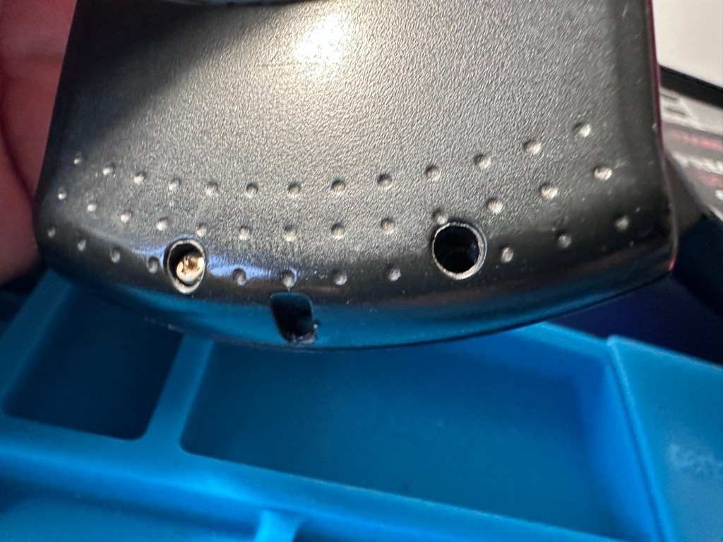
It’s arrived. It’s looking a tad tatty as expected, and those battery terminals are totally corroded. I’m not going to put any power into it at this point as I know there will be no response. I just hope the corrosion doesn’t go much deeper. This is all rust, not battery acid.

We’ve got to get the case separated so that we can review the surprises inside that I suspect are waiting for me.

Repair:

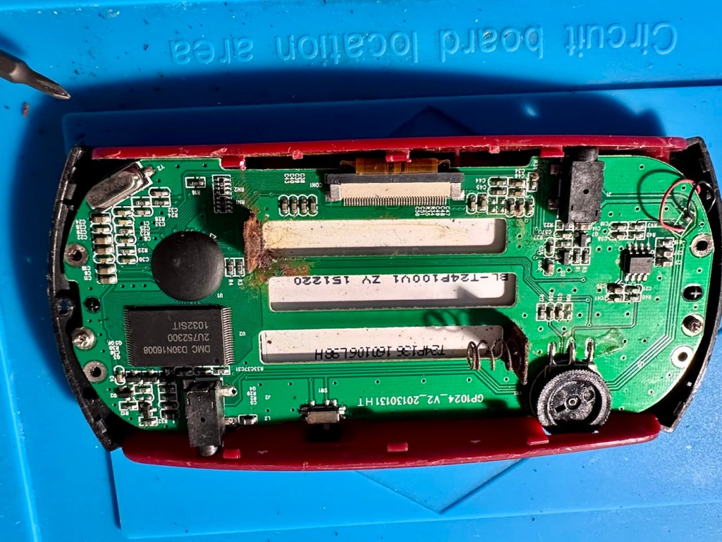
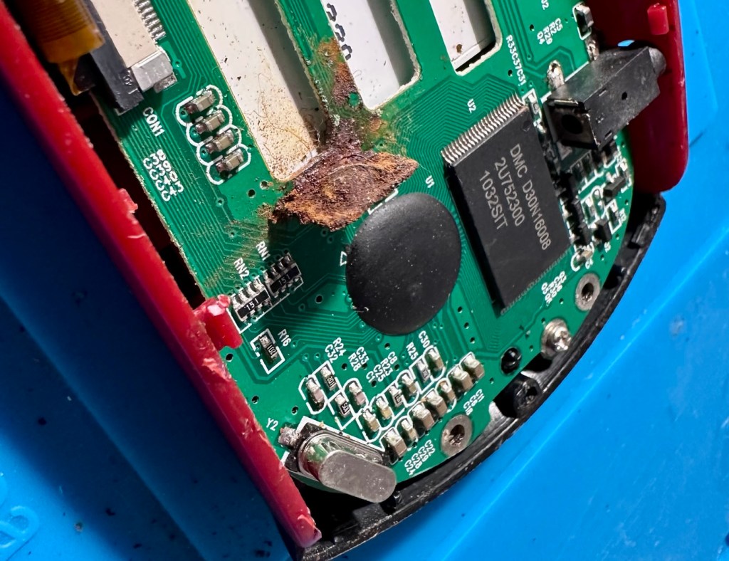
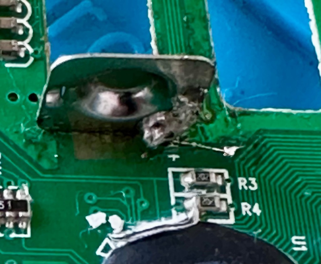
With the cases separated the extent of the damage can be seen. The rust has also completely damaged the two terminals on the main board.

My main concern here is that directly below the terminals is the screen. I’m hoping the source of the problem hasn’t gone any further.

And luckily the terminals are where the rust issue ends.

Ok, first thing I do is remove the rusted battery terminals from the battery compartment and then give the internal shell a thorough clean. I then install fresh terminals and add a couple of jumper wires as I don’t have and double type battery contacts. This is more than sufficient.

Next I need to get the two terminals off of the board, I use a soldering iron for this, and as I’m going to produce a little heat in the area I mask the area between the battery contacts and the screen with a little Kapton tape to give some protection, I could have removed the screen completely at this point, but as I was using the iron and not hot air I didn’t class it as necessary.

Kapton tape under terminals

However, as I removed the two terminals, it became obvious that I would have to remove the screen as the old terminals took the connector pads with them and damaged some of the traces. I was going to have to carry out a more complex repair.

The contacts had to be fastened from the rear of the board, so for this reason it was good that the screen was removed. The screen is quite delicate and is secured to the board with a ribbon cable that had to be detached, and double sided pads that had to be manipulated to release the screen from the board.

I did some testing with the multimeter and there was a good contact on the earth side. However the positive side was dead, no response. Closer examination of the board under the microscope showed that the trace between the positive terminal and a nearby Via point, shows that the trace had also been removed severing continuity. Using a grinding pen on the appropriate Via, allowed me to expose some copper, I was then able to use some flux and apply the tiniest dab of solder. The next stage was to utilise some trace repair wire, only 0.10mm thick. This is like trying to solder a piece of hair, it really is that thin. I was able to connect the wire from the base of the positive terminal to the via and testing proved that the continuity had been restored.

That tiny 0.10mm trace repair

I tidied this area up by adding a touch of UV curable solder mask, to protect that very thin wire from corrosion or being caught while re assembling. It cures in just over a minute under a small UV light and becomes quite solid. It’s good for this purpose.

So now that all continuity on both the negative and positive sides has been restored, I just connect the battery chamber for a quick test before reassembling it all.

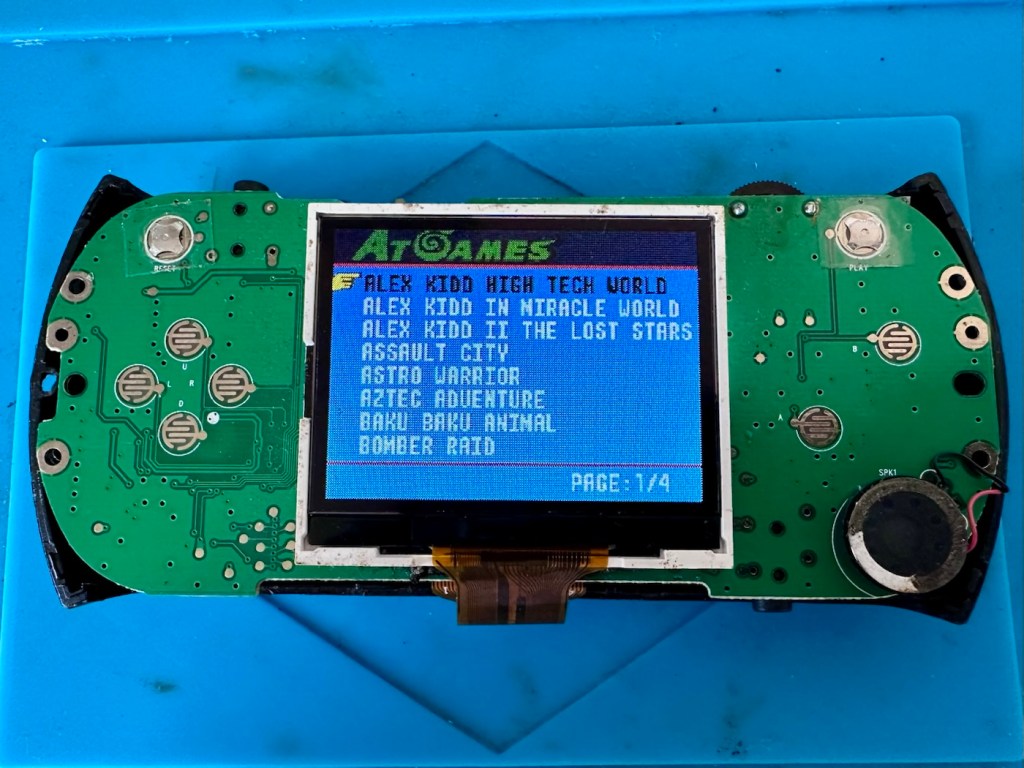
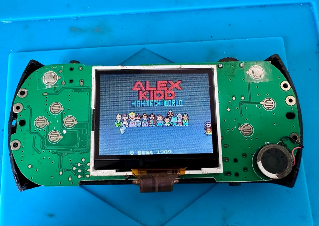
And it works.

We have sound and we have vision. All that is needed now is to fully assemble the case to see if all the buttons and connectors are working as well.

Result:

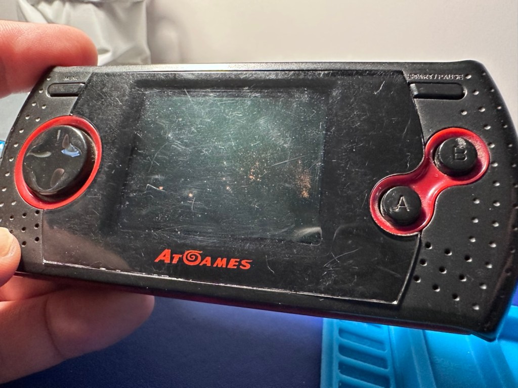
And they are. A quick test shows that all buttons and connectors are in a perfectly good working order, a quick polish and this unit is looking good.

Really pleased with this repair, it was in a very sorry state of repair. However a little persistence and time and I have brought this little unit back to life.

I can understand the seller wanting to dispose of it and I suspect if it hadn’t of sold it would be on its way to landfill. I’ve prevented that and it’s a small win for me as this game will now go on to be used for a few more years to come.

A good result, a good repair and a happy me. Who could ask for more.

Many thanks for passing by. It’s always very much appreciated.
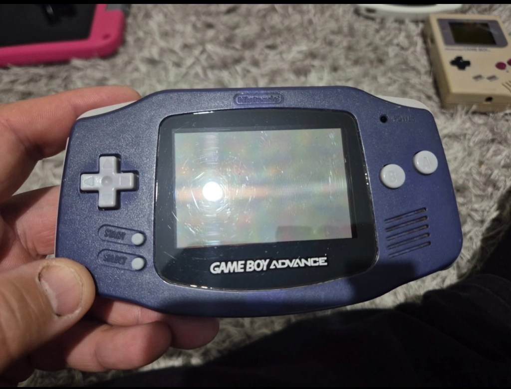
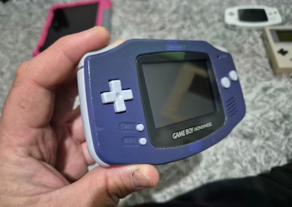
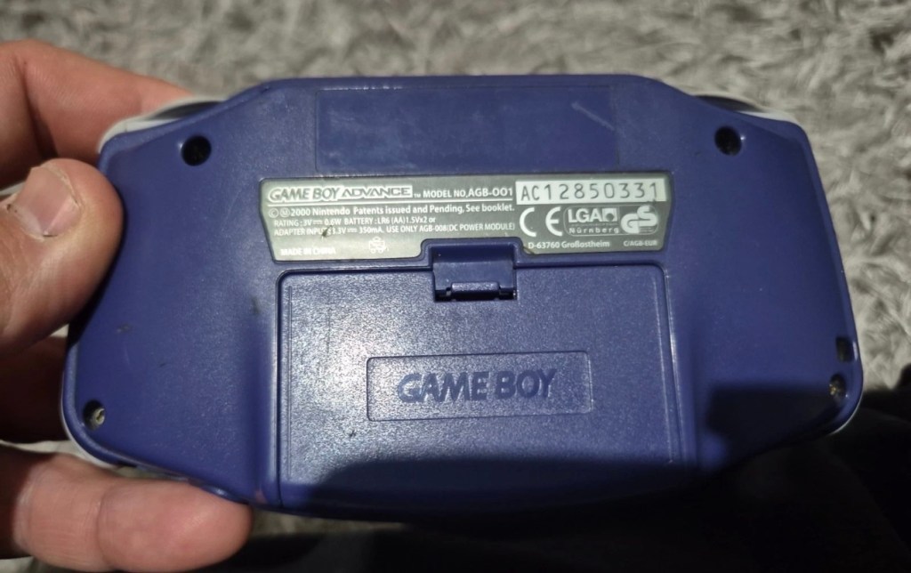
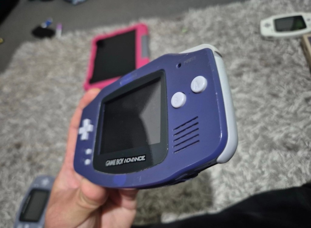
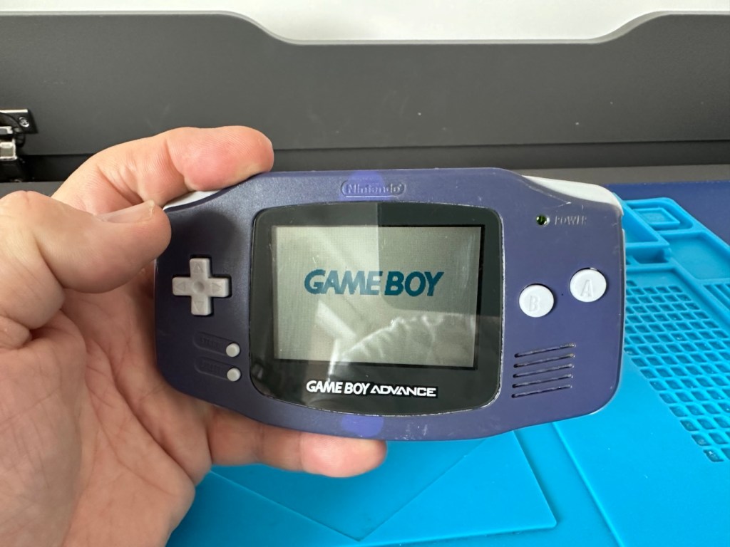
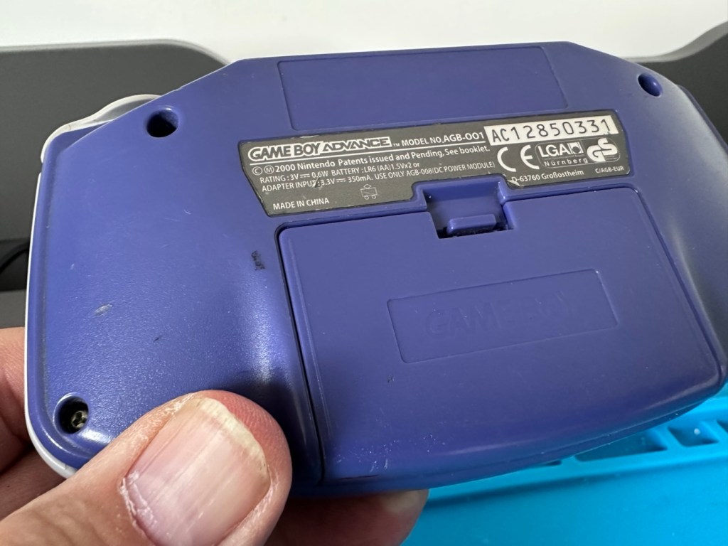
Gameboy Advance

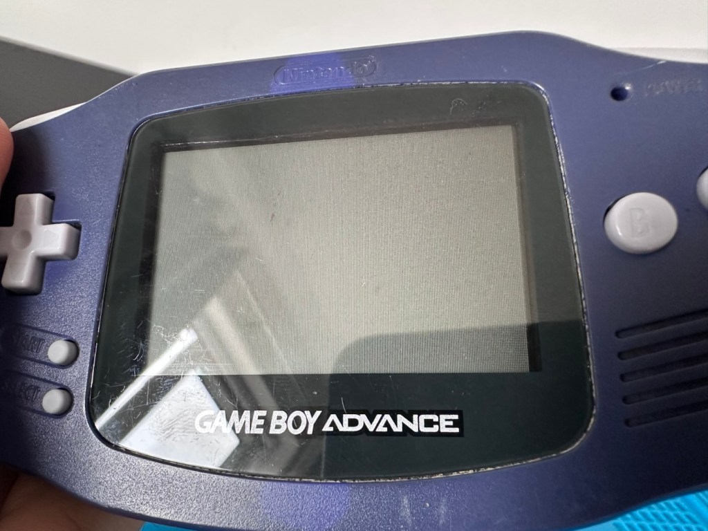
Another one of Nintendos mass produced hand held gaming systems has arrived, with audio issues. It’s a Gameboy Advance, with no sound,so let’s try to fix it.

Here’s what the listing stated:

Gameboy advance console, complete with battery cover, all buttons works and powers on but no sound, has marks on screen and a few marks on shell and scuffs/indentations.

Photos of exact item you will recieve, FAULTY Uk buyers only. Has cover missing that the power light shines through on

EBay

I’ve purchased this as another addition to my collection of handheld retro gaming consoles. As usual it dosen’t work, and that sometimes keeps the cost down a little. This one has cost me £24:00GBP and I’m happy that that is a fair price for one of these units. Here’s a little about the GBA:

The Game Boy Advance (GBA) is a 32-bit handheld game console, manufactured by Nintendo, which was released in Japan on March 21, 2001, and to international markets that June. It was later released in mainland China in 2004, under the name iQue Game Boy Advance. Compared to the Game Boy Color it succeeded, the console offered a significantly more powerful ARM7 processor and improved graphics, while retaining backward compatibility with games initially developed for its predecessor.

The GBA is part of the sixth generation of video game consoles, competing against Nokia’s N-Gageand Bandai’s Japan-only WonderSwan. The original model was followed in 2003 by the Game Boy Advance SP, a redesigned model with a frontlitscreen and clamshell form factor. A newer revisionof the SP with a backlit screen was released in 2005. A miniaturized redesign, the Game Boy Micro, was released in September 2005.

By June 2010, the Game Boy Advance series including revisions, had sold 81.51 million units worldwide, massively outselling its competitors. Its successor, the Nintendo DS, launched in November 2004, was backward compatible with GBA games. GBA sales ended by 2010 after over nine years.

In 2008, the GBA was still Nintendo’s predominant handheld console in terms of market presence and global installed base. It was only in late October 2008 that Nintendo announced that the Nintendo DS had officially surpassed the GBA worldwide in sales. This milestone consolidated the definitive global leadership transition between generations,[13]although in specific markets, such as the United States, the GBA was only surpassed by the Nintendo DS in sales in late 2009.

Wikipedia

Now just to reiterate. These units are now 25 years old, there were in excess of 81 Million of these units produced and they still command a good price today. Just consider how many of those units have been sent back into landfill, the figure is probably immense. But then again we produce many items en masse, and we have been just chucking stuff away for years. The figures must be mad.

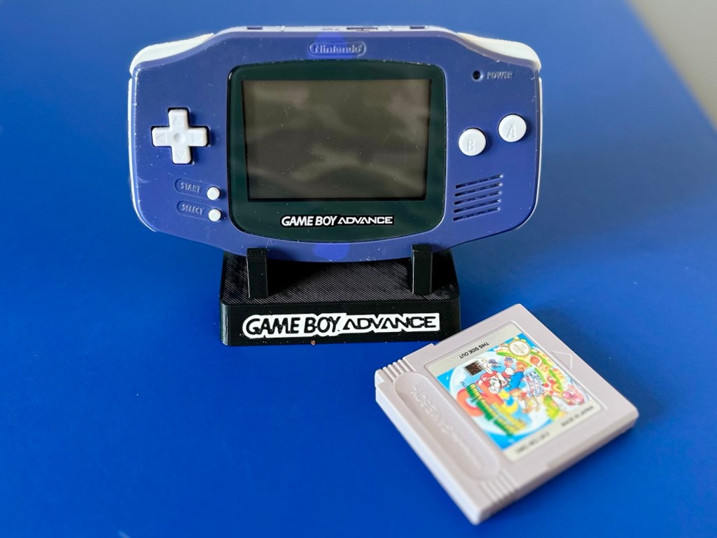
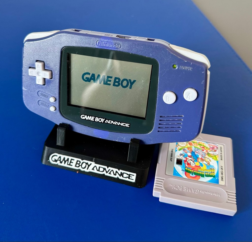
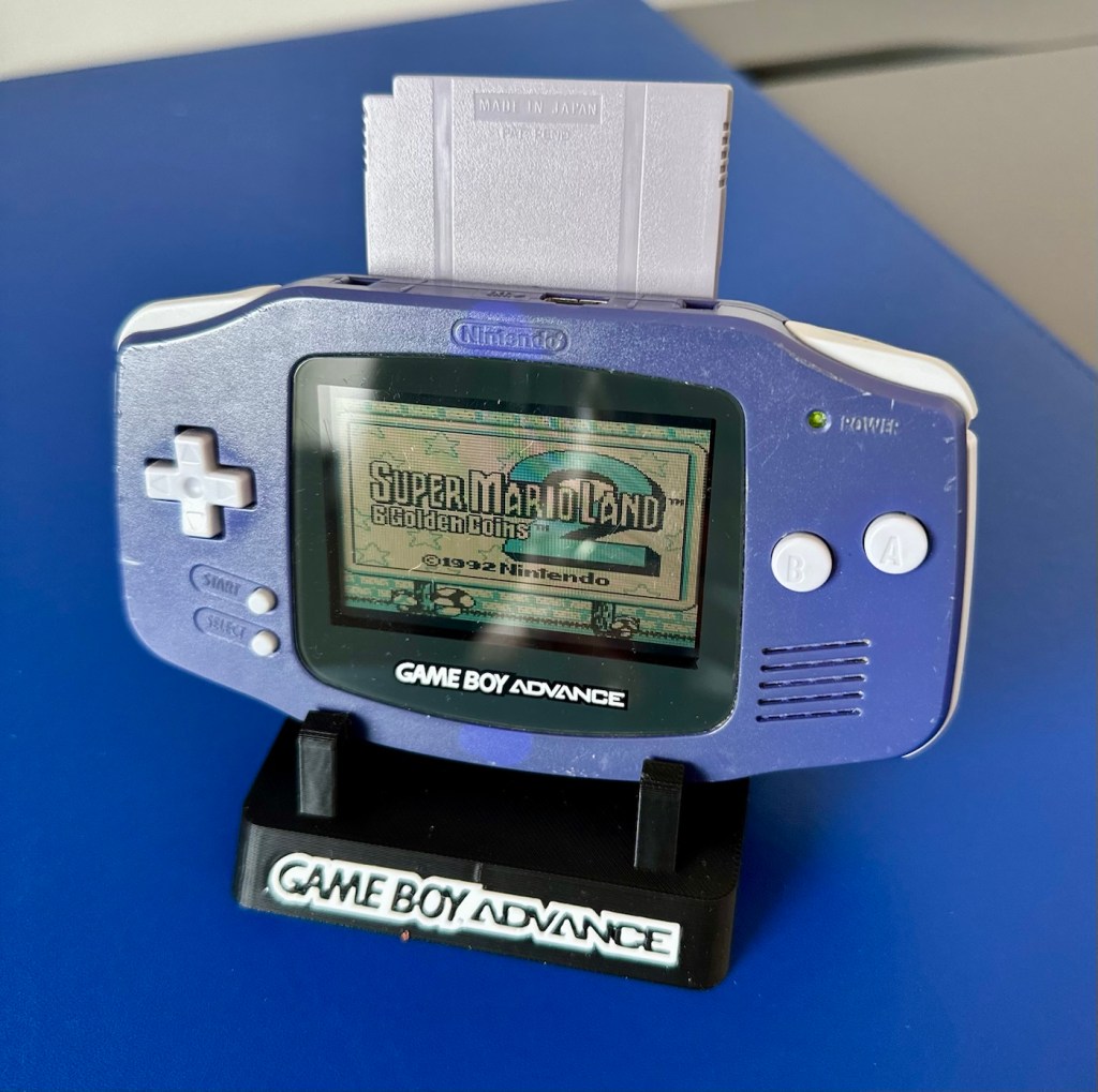
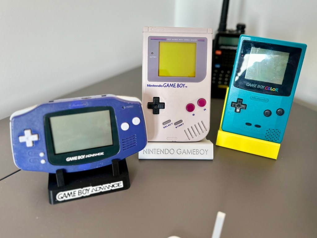
Except for this one. It will be repaired, cherished and reused. And displayed for all to see.

This one has been advertised as having no sound. Just from viewing the sellers photos you can see there is an awful lot of staining around the speaker grill area, maybe some liquid has been spilled here and the speaker is damaged, or maybe the audio capacitor inside has blown. These are usually the two main culprits, but you never know it could be for some other totally different reason. Let’s not make assumptions, let’s see what turns up.

Assessment:

The unit has arrived all in one piece. The battery cover is in place, a little loose at the clip but I might be able to strengthen by heating and gently manipulating it.

Battery contacts show no sign of corrosion but are a little grubby. There are signs of good use but nothing really bad to be honest, all connectors and buttons appear to be doing what they should. The unit is in good need of a thorough clean, as it does look a little worn in that aspect. Screen has very minor scratches, nothing that will cause any issues. The little acrylic lens by the power light is missing and there is as stated, no sound even though we do have a picture and are able to play the games. In all aspects the unit is functioning, just with no audio.

This is a fair unit, it will clean up and if we can get the audio working we have a potentially very good unit.

It is dirty though, and a good clean will make an immense difference.

Repair:

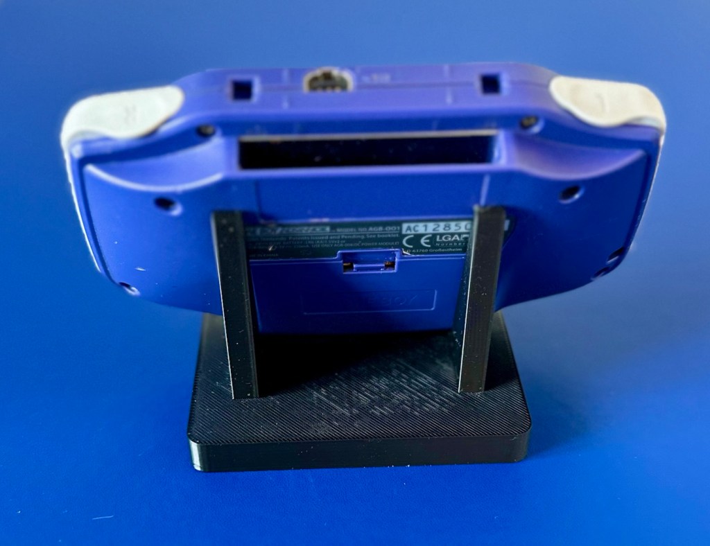
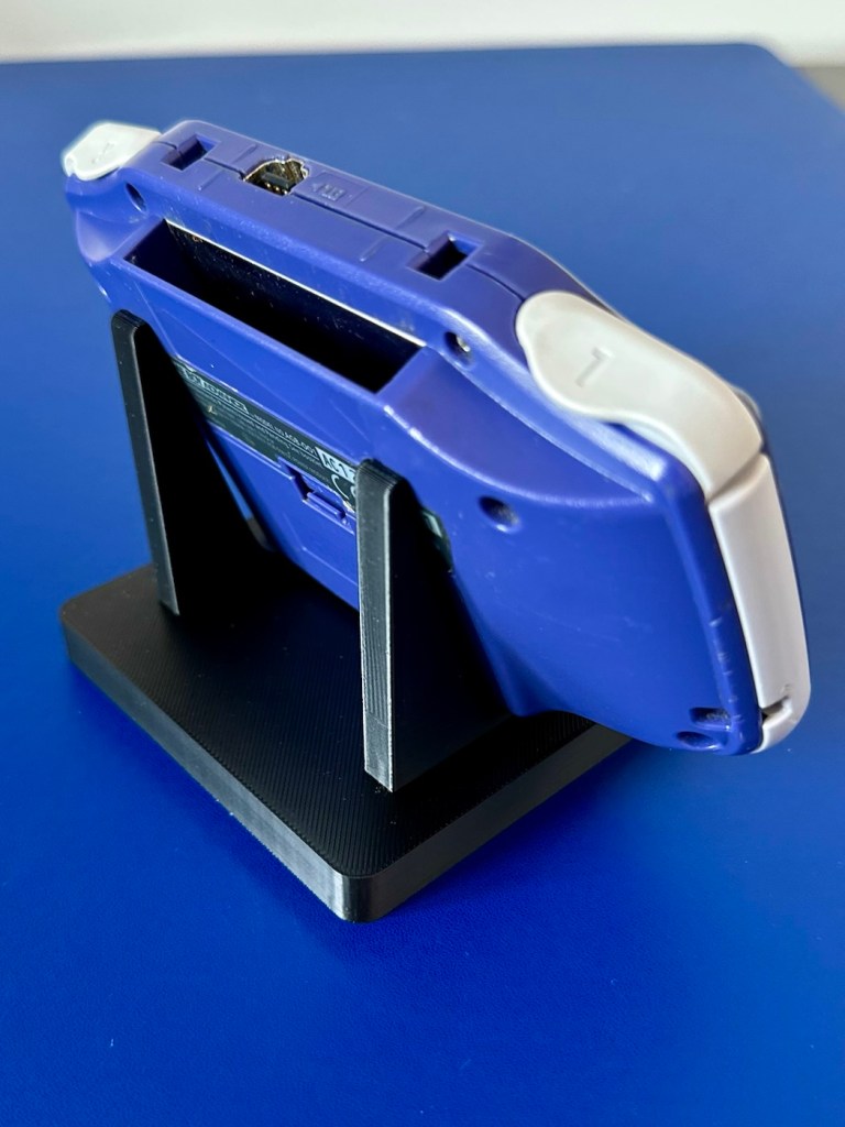
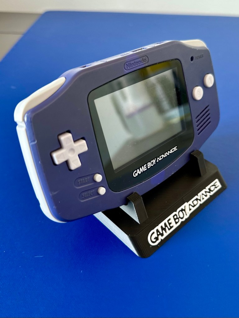
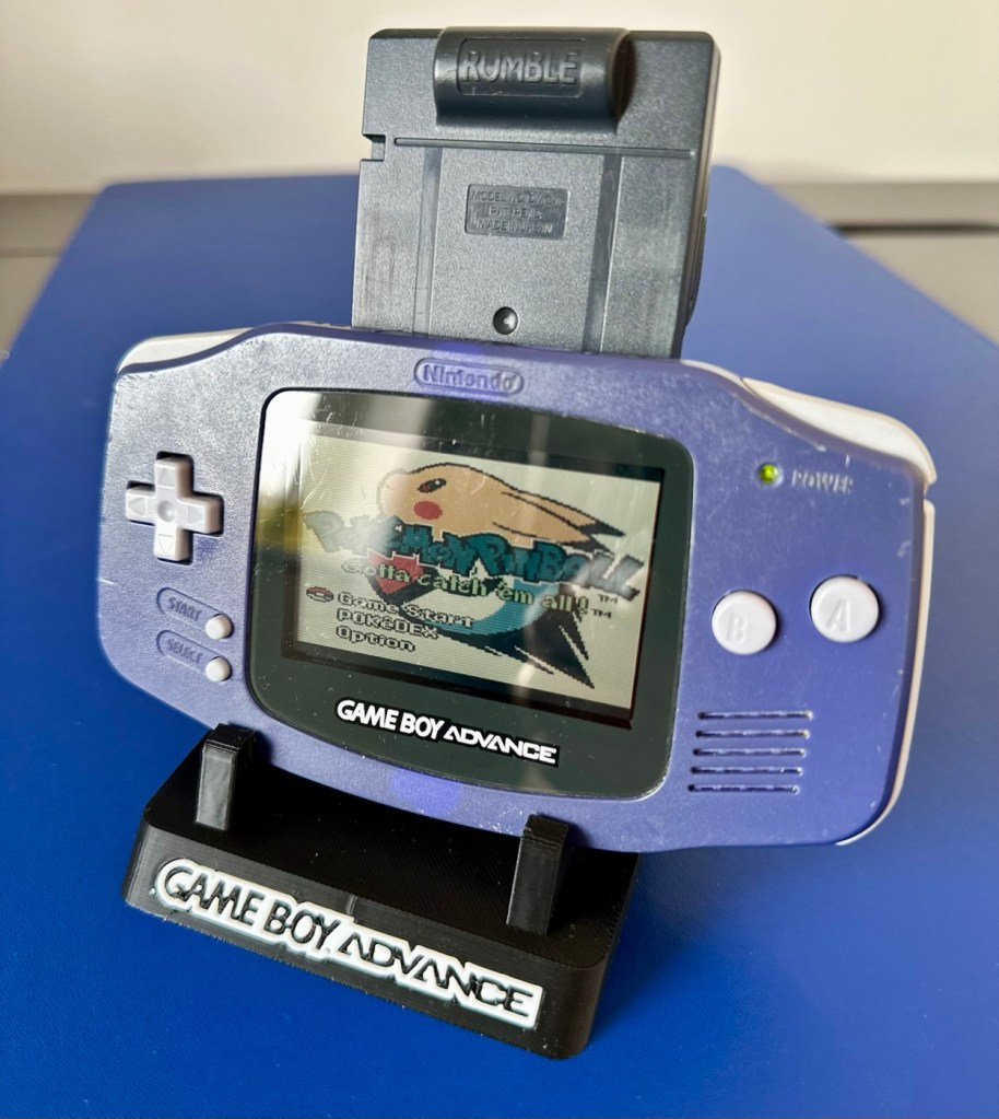
The printer is on and warmed up so before we get repairing, let’s print a suitable display stand for this unit.

Display stand printing

Now let’s open up the unit and see what we have inside.

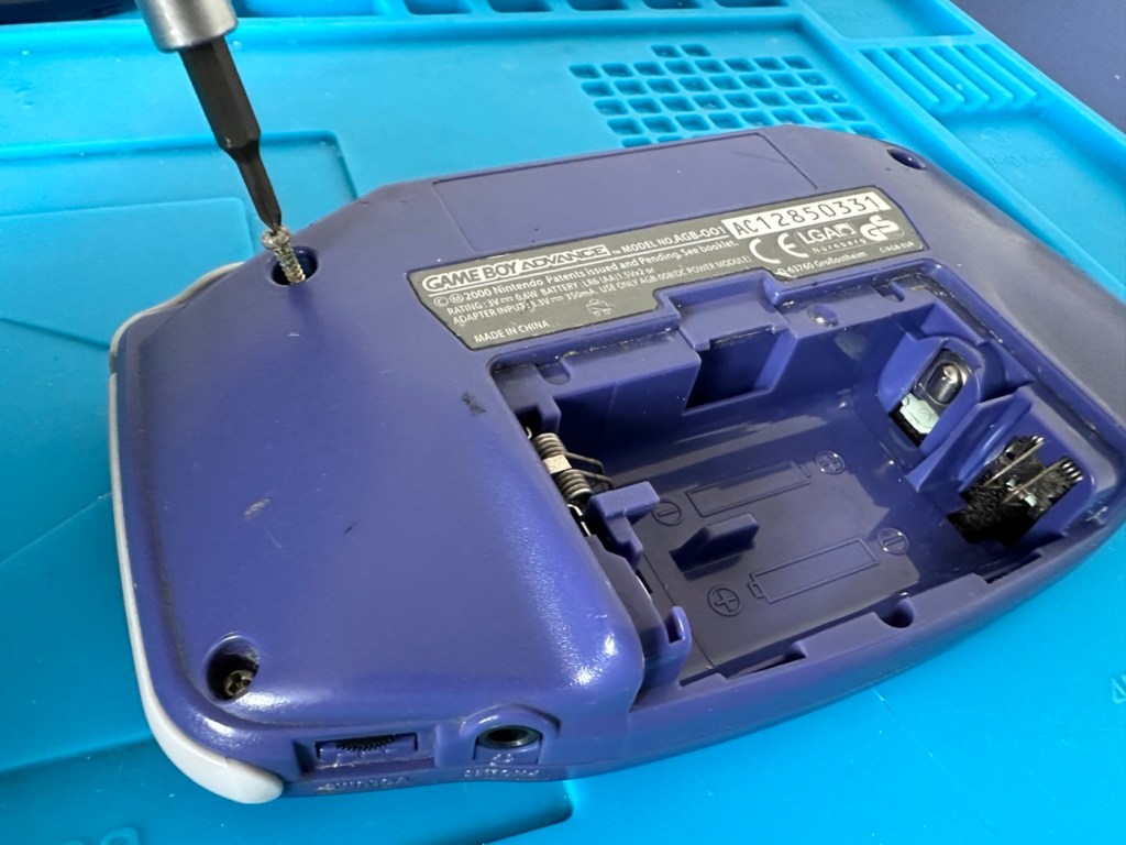
First there are seven tri wing screws securing the shell. Remove these and the rear of the unit just lifts off.

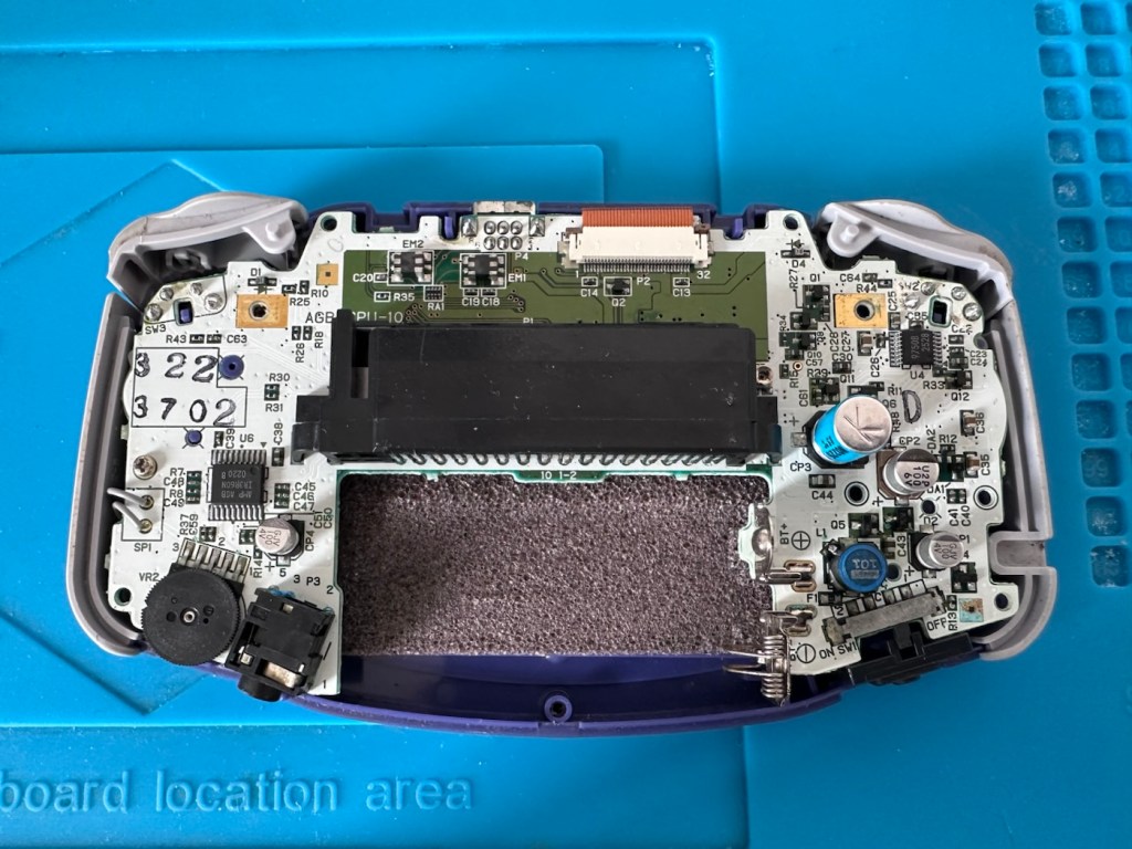
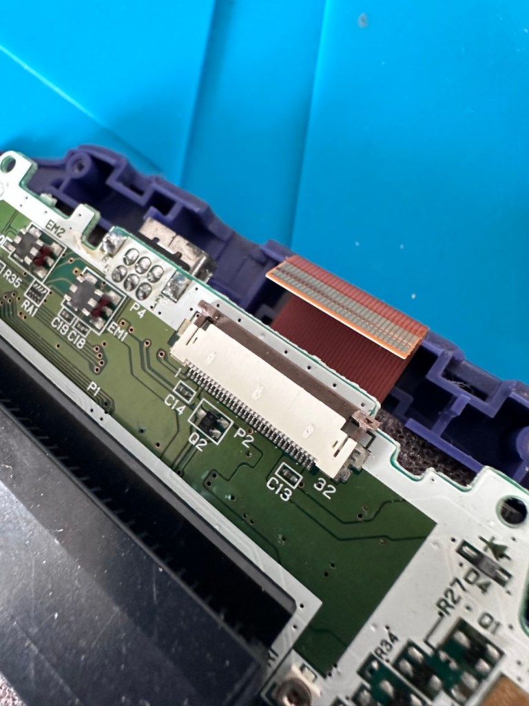
Next there should be three screws to remove the mainboard but there is only one. Someone has previously been in this unit and has left two screws out. Next we remove the ribbon cable that secures the screen to the mainboard.

We now have free access to both sides of the board and can put everything else to one side to start our fault finding process.

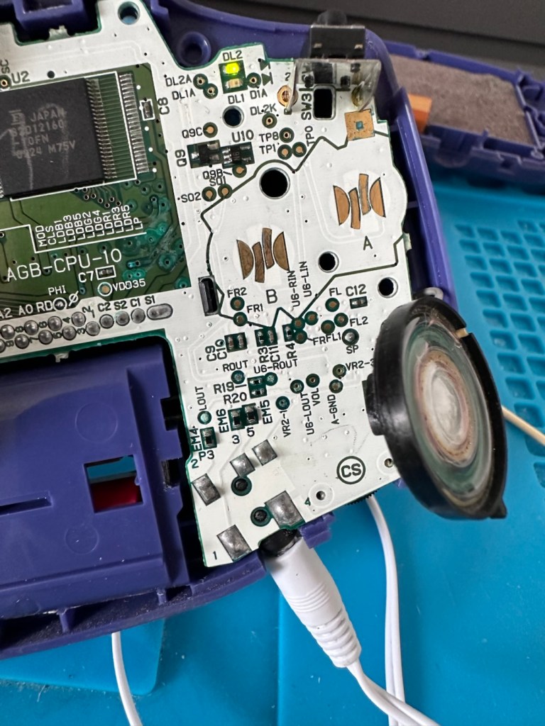
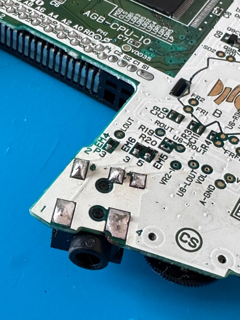
First things first, let’s check the speaker. With the multimeter it’s showing 8 Ohms so I’m happy that the speaker is ok. A quick check for shorts and not one capacitor shows a short, I plug in a set of headphones and I can hear sound, but as soon as they are unplugged there is no sound again. My attention is now at the earphone socket.

On close examination other is a considerable amount of battery acid contamination in the earphone module. This is strange as there is none evident in the battery contact area. A close look around shows some spots of contamination, however these are easily cleaned with some IPA. I have a feeling this may have been a previous issue and the person in here prior to me, has cleaned up, but given up on the repair.

I remove the earphone module, and clean the surrounding area.

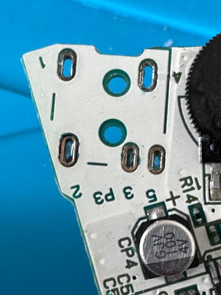
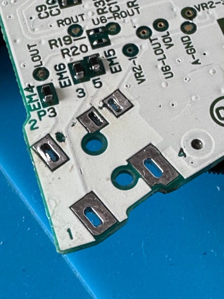
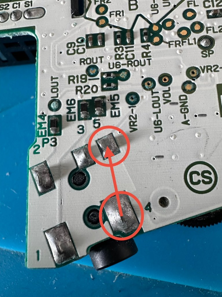
A simple check here is to see if there is any continuity between the two tabs that occupied positions 4 & 5 as marked on the mainboard. This check is carried out on the actual module. If you have continuity between these two pins, then in theory the circuit is good, and the speaker should be working. My results here were negative as there was no continuity on this module between those points.

The way the earphone works is thus. Plug the earphone jack in, it opens up the contacts and by passes the external speaker. Remove the earphone jack and the contacts close, opening up the main speaker. If there are contaminants on the contacts, this can prevent continuity and hence there is no sound on the main speaker.

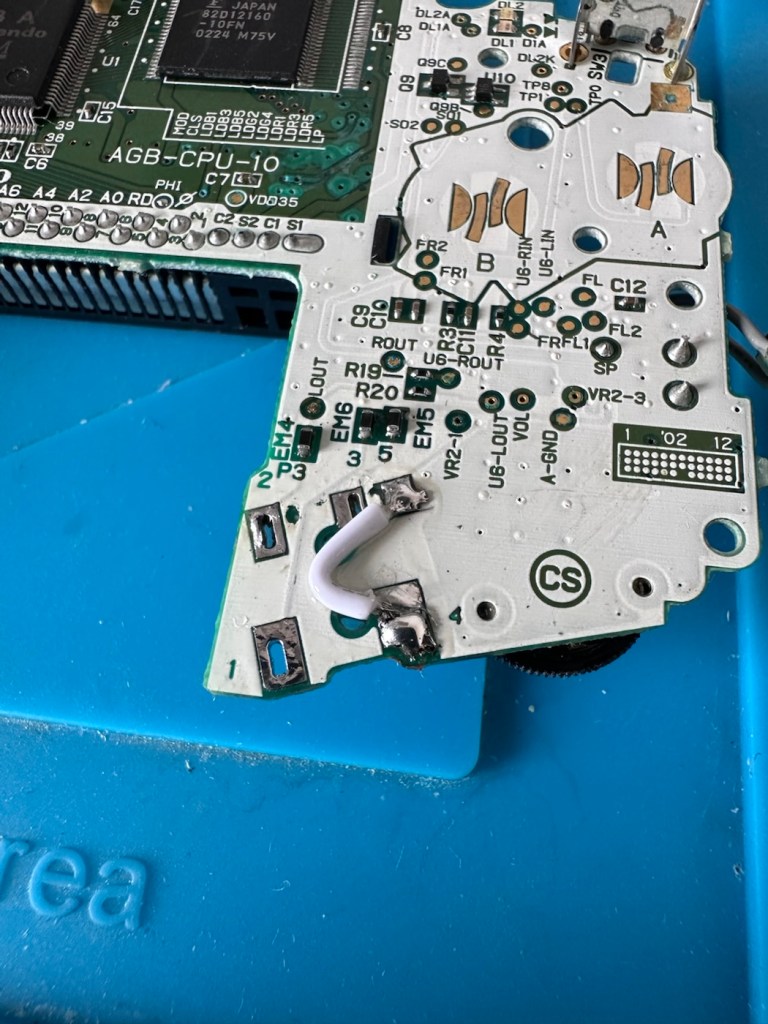
You can double check that this is the issue by soldering a small wire between points 4 & 5 on the mainboard in theory by passing the earphone circuit leaving the speaker circuit open and accessible.

And my suspicions were correct, this small video below was the result of bypassing this part of the circuit.

We have sound in the speaker

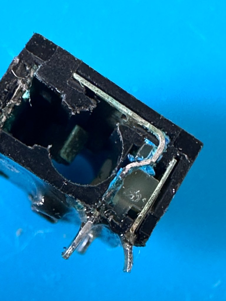
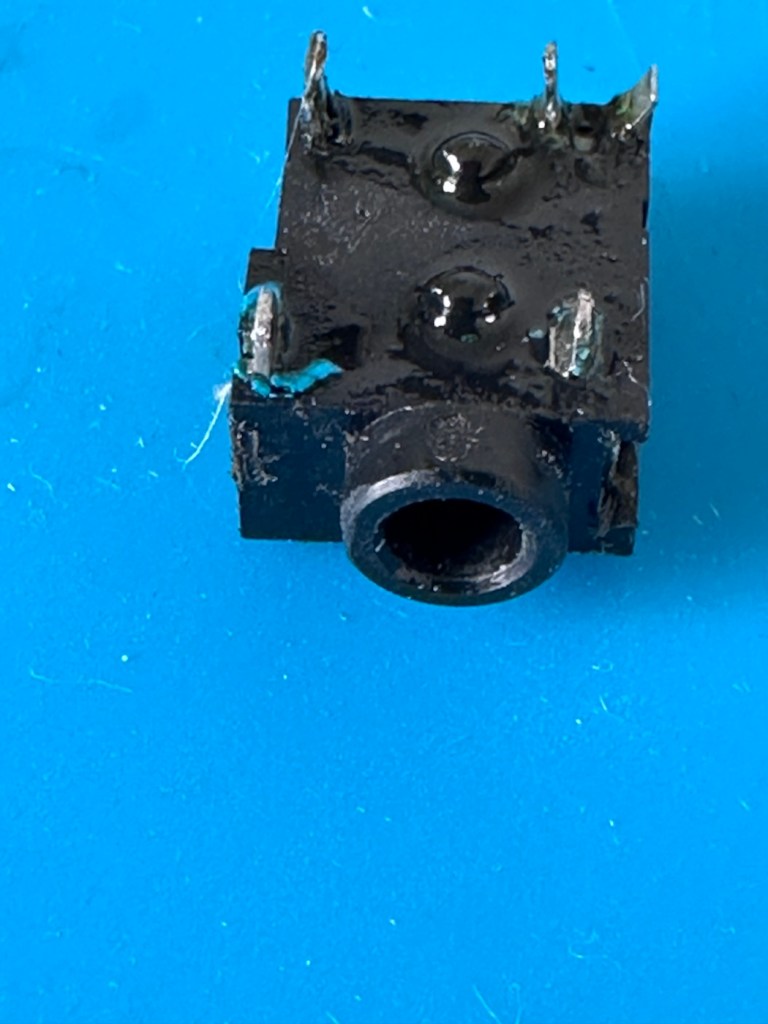
Looking inside the earphone socket it was easy to see this piece had a solid lump of contamination exactly where I was expecting to see it. I have no spares of these and to obtain one off of the auction sites is an absolute ripoff. I can order one from our friends in China but I’m looking at a four week turnaround here, and I’m inpatient and not willing to wait that long. I’m going to try and repair it.

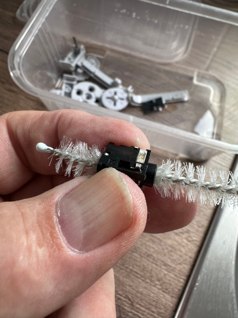
I’ve gathered everything up that needs cleaning, buttons, connectors, screws, pads and the suspect connector, and dropped the lot into a small dish of white vinegar. White vinegar is great for removing contaminants and you can actually watch it fizzing away and working. I left these items bathing for about 30 minutes before giving them all a good scrub clean. On the earphone jack I “borrowed” a small bottle cleaner from the wife, it fits right through one side and out the other allowing you to get a really good scrub inside.

White vinegar and a bottle scrubber

I also cleaned the outside thoroughly removing all signs of contamination, the tabs were gleaming when I finished. I then put everything I’d just cleaned in between two sheets of kitchen roll and put them in a cooling oven to dry off.

When dry I took the bottle cleaner again, inserted it back into the earphone jack, sprayed quite a bit of electrical contact cleaner back onto it and vigorously scrubbed again for the next few minutes. When dry, I took the multimeter and again checked for continuity across points 4 & 5 and a tone was heard. Continuity had been restored and the earphone contacts were now working. Plugging in a jack and then removing it confirmed that all was working as it should. It’s now time to put this jack back on the board.

Earphone port, back in place

Final touch is to put a tiny pice of clear silicon in place of the missing power light lens on the front of the case. Job done.

Time to reassemble this unit.

Result:

And here we are. The original unit has been thoroughly cleaned, it’s come up ok but is probably a good candidate for a case upgrade and a Capacitor change at some point. That’s just cosmetic though, what really matters is that this unit is now working perfectly, and it sounds just fine.

This unit actually came from a guy who restores these units, I guess he was just having an off day as to be honest, it wasn’t the most difficult issue to diagnose and repair. It honestly took longer to clean this unit than it did to repair it. I’m pleased that I’ve used all the original parts and just been able to do a proper restoration as such.

81 million of these units were produced, so this is just one in that 81 million, that has been saved again from landfill to be enjoyed for many more years to come.

Thanks for passing by. Always most appreciated.

Nintendo Gameboy color console

I’ve purchased a faulty Gameboy Color for my collection. It has no power, so let’s have a look and try to get it working again.

What the listing stated:

Very clean, but doesn’t turn on

EBay

Yep. It’s a Gameboy Colour to me, but as it was sold using the American spelling of “Color” then that’s what it will be addressed as, going forward.

I’ve been after a “Color” to add to my collection for a while now, but it had to fit my very strict quality requirements, in truth it just has to be faulty, and this particular example has met my conditions. I’ve paid £30.00GBP for this example and I’m happy with that, it’s a very fair price.

The good news seems to be that it is in a really good condition, it looks as if the battery door is missing, however they are freely available and this is not an issue should I require one.

These units are known to sustain power failures and the repairs are well documented. By now the unit is close to 30 years old and as time advances components start to fail, these include, but are not limited to:

  • Power switch failure: either a complete failure that requires replacement or quite simply a simple clean to remove years of tarnish and environmental gunk.
  • Fuse failure: there are two fuses F1&F2 that are known to fail, normally due to a short somewhere else on the circuit, but sometimes due to a power surge or incorrect addition of an incorrect power supply.
  • Via failure, small through the board connectors that are known to suffer with corrosion, requiring intervention with the addition of small wires to bypass the issue.
  • Capacitors – known to fail on a regular basis, it’s sometimes good housekeeping just to get these replaced as they are a contributing factor as to why other components such as the fuses also fail.
  • Worst case scenario: major corrosion or main board component failure.

We’ll cross these bridges when and if we need to.

Here’s a little info about the Gameboy Color console:

The Game Boy Color (abbreviated as CGB or GBC) is an 8-bit handheld game console developed by Nintendo. It was released in Japan on October 21, 1998, and in international markets the following month. Compared with the original Game Boy, the Game Boy Color features a color TFT screen instead of monochrome, a CPU running at up to twice the speed, and four times as much memory. It is backward compatible with games developed for its predecessor. The Game Boy Color was released during the fifth generation of video game consoles and competed with Bandai’s Japan-only WonderSwan, SNK’s Neo Geo Pocket Color, and Sega’s North America-only Genesis Nomad.

The handheld is slightly thicker, taller and has a smaller screen than its immediate predecessor, the Game Boy Pocket, but is significantly smaller than the original Game Boy. As with its predecessors, the Game Boy Color has a custom 8-bit processor made by Sharp. The American English spelling of the system’s name, Game Boy Color, remains consistent throughout the world.

Wikipedia

So, for now, let’s not speculate on its quality and issues until it arrives, when we can then carry out a proper assessment of the unit that has been received.

Assessment:

The package has arrived. The battery lid is missing as kind of expected, I will get a replacement sometime, but for the moment I’ll probably print one out on the 3D printer, it’ll be a totally different colour as I don’t have a “Teal” coloured filament to use. The product label on the rear is also damaged but I can easily get one of these as a replacement, however it’s not essential and will only be of cosmetic appeal.

Missing battery cover and old product label

The front fascia is in a good condition with only a minor scratch on the screen, however there are a couple of dents and dinks on the body where it looks as if it’s been dropped or bashed at some point.

Front fascia is good

All ports, switches, buttons and sockets look ok and seem to be operating as such with no resistance or signs of stickiness.

Again, the casing is in general fit to use, and in no way causes any issues with its operation when working. It is purely a cosmetic issue that i can address when the unit is finally working.

I have installed two AA size batteries, switched the unit on and it is most definitely dead. Repeatedly flicking the switch does nothing at all, so it is a situation where the unit will have to be opened up and further investigated. The assessment has not thrown up any other issues not already highlighted in the sales documentation, so in general I am quite happy with the outcome at this stage. let’s get inside and see what we can find.

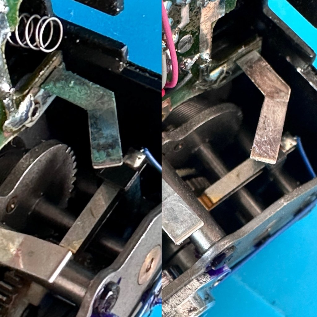
Oops. Wasn’t expecting that. I’ve removed the six “tri” screws and as soon as I’ve separated the two halves, an amount of what looks like battery corrosion “crap” has fallen out as well.

Oops – corrosion is present

With the two halves separated, I then remove the screen ribbon cable, remove three more screws and the main board lifts out.

There’s some good news here. The contamination looks as if it has been completely isolated to within the battery area, there is no sign of any damage to the Vias, or any other components on the main board.

I have obtained the schematic diagram for this circuit board for checking continuity, and i’ve been able to confirm there are no issues with any contamination damaging any traces to the board. We’ve been very lucky here, dodged a bullet, to coin a phrase.

Schematic diagram

I have removed a set of battery contacts from the battery area, and replaced these with a new set that I have in my spares box. I could clean these, but it’s good to remove all items that were originally contaminated and very possibly contributory to the fault we have today.

I have also cleaned the front and rear of the main board with IPA just to ensure that if there was any issues with contaminants on the board, they’ve now been removed.

The switch has been tested electrically with a multimeter and this is working fine. The three capacitors have been looked over and seem to show no signs of wear or deterioration, they haven’t been properly tested though, so let’s now check fuses F1 & F2.

For reference: Fuse F2 protects the DC jack, whilst F1 protects the battery compartment. Using the continuity mode on the multimeter, a continuity through the fuse should present an audible buzz that let us know the fuse is complete and has not failed in any way.

I start on F2 and get a healthy buzz that tells me F2 is working fine. However fuse F1 is a different story, there is no continuity and there is no sound, I check again and can confirm that this fuse has blown, maybe this is a result of the contamination that was in the battery area?

The two fuses, F1 is dead

I’ve now attached the bench power supply supplying a 3v input to clarify the fault.

A 3v supply proves the fault

Fuse F2 has a 3v supply on each side, however our suspect fuse F1 only has a 3v supply on one side confirming that this fuse has blown. Once this fuse has been replaced I can check the voltage supplies on the remainder of the board, especially on the DC-DC regulator board, that supplies varying voltages from 3v – 13.6v required around the main board. On the main board the voltage regulator can be recognised as U5.

DC-DC voltage regulator U5

A quick check for short circuits doesn’t show anything of concern, maybe when the fuse is replaced it may well open up some other issues, the fuses I will be using are “resettable” fuses. These fuses seem to be the standard now for these units. Most resettable fuses—known as Polymeric Positive Temperature Coefficient (PPTC) or polyswitches—reset automatically and do not have a physical reset button. Once the underlying overcurrent or fault condition is removed, you simply disconnect the power source to allow the fuse to cool down, then you switch on again, if the same issue occurs, there is an obvious issue present that needs investigation, as stated above, once the faulty fuse is replaced I will be able to check other areas on the mainboard for correct voltages.

Just for information the fuse that needs replacing is approximately 4mm in width. You can see the scale in this picture taken alongside a ruler.

The tiny suspect fuse

Let’s get on with the repair.

Repair:

First off I’ve printed a replacement battery door cover. As stated earlier I don’t have any “Teal” filament so I’ve printed it out on a purple filament. For the purposes of practicality (holding the batteries in place) it will serve a purpose whilst carrying out the repairs.

I have a replacement fuse, this work will now have to take place under the microscope as it’s just so tiny, think grain of rice size and you will understand just how small this component is, and it’s amazing that a component so tiny can completely shut down a unit such as this.

The supplied fuse is even smaller than the one on the board. If the original was 4mm then this one is probably around 1-2mm it really is minute. Here’s a comparison of them side by side on the microscope base.

Tiny and teeny tiny….

That said I’ve removed the old fuse, wicked away the old solder and applied some flux and a couple of new dabs of solder. Compared to these new fuses the solder looks massive, I can assure you it isn’t and is greatly magnified.

With the bench power supply providing 3v I’m able to use the multimeter to confirm that the fuses are both working, however there is another issue and I suspect it is something I discussed earlier, but omitted to heed my own advice, about good housekeeping. I’ll come to that in a second.

Power is getting around on the 3v rail and is not an issue. However at the Dc converter I’m not getting the 5v or 13.6v rail, so there is another issue. The new fuse has dropped out again, and this is good as it proves it works. I let it cool for 30 seconds and it is back up and working and I’m able to continue tracing the fault. The big capacitor C32 that sits beside the DC-DC converter appears to be carrying a short, it is probably this that has caused the fuse to previously fail.

And my good advice was to change these capacitors for good housekeeping purposes…..and I didn’t.

Guess what I will be doing next?

There are three Capacitors on the main board and below you can see what their primary functions are:

  • C32 (Main Power / DC-DC Filter)100µF, 6.3V (Filters the incoming voltage; if faulty, the system won’t boot or will repeatedly reset).
  • C35 (LCD Display Filter)22µF, 16V (Stabilises the voltage to the liquid crystal screen; if faulty, it results in a dim or washed-out image).
  • C38 (Audio Amplifier / Sound)100µF, 4V (Powers the speaker and headphone output; a failure here is the leading cause of whisper-quiet audio).

Ok. Fortunately I have plenty of capacitors in my spares box so I was able to replace the three capacitors with no issue.

This done I then decided, prior to any reassembly to see if the power was now being distributed as it should, and I’m pleased to say it is. We have the full range of voltages now coming out of the DC-DC converter.

Now let’s get the unit reassembled, cleaned and then get some tasty pics taken👍

Result:

To finish it off and whilst the 3D printer was still warm, I’ve printed a simple brightly coloured yellow display stand to show it off on.

A new printed display stand

After a good clean the unit is now in a perfectly good working order. The fault appears to have been the faulty capacitors and battery contamination all probably combining to make the power fuse fail, a perfect storm if you like. The fuse and three capacitors have now been replaced to breathe new life into this game console. Cosmetically it’s still tatty and would probably benefit from a new outer shell and some labelling, however it works and to be honest that is all that really matters.

A small video showing the unit working

I wonder how many of these items just get thrown away because they don’t work? This probably took me about three hours in total with diagnostics and repair. Another piece of retro history restored, now joining my original Gameboy classic as part of my collection.

It’s been a pleasing little project, enjoyable and educational and it’s always good to hear the familiar beeps when it springs back into action.

Another one saved from landfill.

Thanks for passing by, as always it’s very much appreciated.
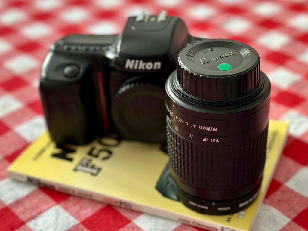
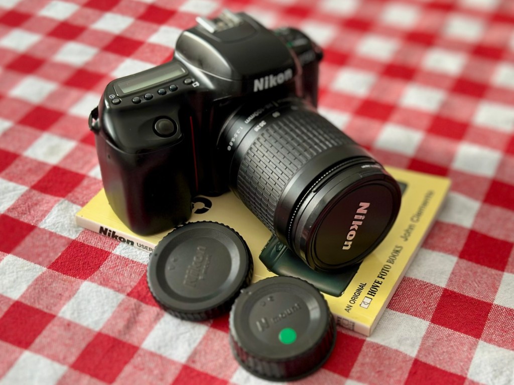
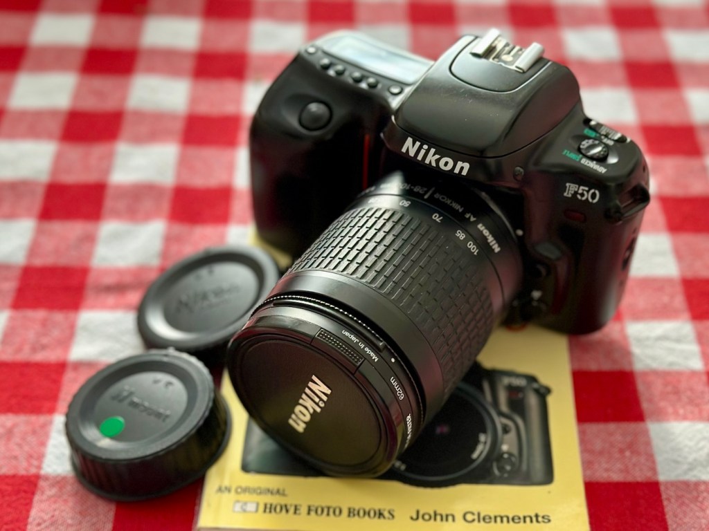
Nikon F90x 35mm SLR Film Camera and MB10 battery grip

This camera influenced the partnership between NIkon and Kodak to produce one of the most expensive prosumer cameras of the 1990s. However this one is a lot less expensive but with some issues. Let’s have a look at it:

What the listing stated:

THIS UNIT IS FAULTY
SUTIBLE FOR SPARES / REPAIRS ONLY
SOLD AS SEEN

FAULTS INCLUDE BUT ARE NOT LIMITED TO,
MIRROR STICKS


COMES WITH EVERYTHING SEEN IN IMAGES

NO WARRANTY PROVIDED

EBay

Just couldn’t let this one go. Whilst browsing the sites for my next challenge last evening, this little bundle of joy just popped from one of my preferred sellers for a quick sale, it was about 11pm and was just posted at a sale price of £30:00GBP, however with a voucher I had, I was able to secure it at £27:00GBP. Considering this is a good quality camera of the mid 90s it also comes with the added bonus of an MB10 battery grip, superb value in my eyes. A lot of camera for a very low price.

Here’s a little bit about this camera:

The Nikon F90x is a 35mm autofocus SLR using Nikon’s F lens mount. It was targeted toward the advanced amateur or prosumer; its feature set is comparable to that of Nikon’s current D100/200/300 SLRs. The name N90s was used for marketing in the United States; everywhere else, the camera was called the F90x. This camera was also used as the base for the Kodak DCS 400 series of digital SLRs.

The N90s/F90x was introduced in 1994 and discontinued in 2001. The camera’s predecessor, the N90/F90, was introduced in 1992 and discontinued in 1994. The successor to the N90s, the F100, was introduced in 1998.

Features & Specifications

Nikon N90s global naming N90S adapted into Kodak’s DCS460, a 6 Mp Digital SLR

  • Bright viewfinder with 92% coverage, .78x magnification
    • Current settings are displayed at the bottom of the finder; information area is automatically backlit in dark conditions
  • Top LCD displays current settings and facilitates changes
    • Backlit for use in dark conditions; the backlight switch is near the left die of the viewfinder
  • Cross-Type Wide Area AF System
    • Choice of wide-area or spot AF
    • One CAM246 AF sensor
    • Continuous AF mode with release priority in addition to standard AF with focus priority
  • 4.1FPS capable with continuous AF; 4.3FPS with standard AF
    • 2FPS mode available
  • 3D Matrix Meter when used with a D or G-type Nikkor lens
    • Center-weighted and spot metering are also available and usuable with AI lenses
  • 3D Multi-Sensor Balanced Fill-Flash capability (with Nikon Speedlights SB-800/80DX/28DX/28/27)
  • Seven Vari-Programs: Portrait, Portrait with Red-Eye Reduction, Hyperfocal, Landscape, Silhouette, Sports, Closeup
    • Explained in detail in the instruction manual
  • Four exposure modes: Program, Shutter-priority, Aperture-priority, Manual
  • Shutter speeds of 1/8000 – 30 seconds + Bulb
  • Flash sync speed of 1/250
    • Flash sync modes: normal, slow, rear, red-eye, FP high-speed
  • Self-timer: 2-30 seconds
  • ISO/ASA Range 6-6400
  • DX-enabled (automatically reads speed information from film canisters)
  • Eyepiece shutter stops excess light from entering the viewfinder and interfering with metering
  • Overall strong build throughout (comparable to Nikon’s current D100/200/300SLRs)
    • Stainless steel lens mount
  • Requires 4 AA Batteries
  • Extensive system compatibility & accessories; see below

Accessories & Compatibility

F90X with MB-10 grip

The N90s/F90x is compatible with nearly all Nikkor F-mount lenses as well as all Nikon SB series speedlights.

Additional, camera-specific accessories available are:

  • MF-26 Multi-Control Back
    • Long Exposures to 100 hours
    • Freeze Focus: triggers the shutter as soon as a subject comes into focus
    • Custom Reset: customizes which settings are affected by the green-button reset
    • Date Imprinting: can also imprint shutter speed and aperture information
    • World Clock
    • Flash exposure compensation
    • Interval timer: up to 100 hours between pictures for 99 frames
    • Limit frame count in continuous shooting mode
    • Multiple exposures
    • Customize which settings are affected by AE-L and AF-L (auto-exposure lock and autofocus lock)
  • MF-25 Data Imprint Back
  • MB-10 Vertical Grip
    • Takes 4AA batteries or, with the MS-11 battery holder, two CR123 lithium batteries
  • Interchangeable focusing screens
    • E screen provides grid lines in the viewfinder

with 28-80mm, 20mm and 80-200mm

Lens Compatibility

  • All functions, including autofocus, work properly with Nikkor AF, AF-I, AF-D, and AF-S lenses.
  • AI and AI-S lenses are usable, with the loss of these functions:
    • Autofocus
    • Shutter-priority exposure mode
    • Programmed exposure mode
    • Vari-program exposure modes
    • 3D Matrix metering (though center-weighted and spot metering remain functional)
  • The camera does not use VR with any lens.
  • G-type lenses (lenses without aperture rings) can be used with the loss of some functionality: only the lens’ smallest aperture can be used in manual or aperture-priority exposure modes.

Camera-wiki.org

Now my experience with this seller is that unless it is absolutely perfect he will not even entertain it. He doesn’t take the time to check and fettle, if it isn’t working from the start he will just get rid of. This attitude of his has meant I’ve had some right bargains in the past with very little wrong with them. I refer you to a recent purchase Canon EOS D60 that had very little wrong with it, but was also a lot of camera for a very low price.

Now I’ve always wanted a Kodak DCS 400 series camera, especially a 460 version as it takes me back to my days when I was working at Kodak in Harrow, I remember when the DCS 400 series came out and back then they were introducing such a new technology that they were commanding a huge price of around $35,000 at the time. These cameras were basically digital versions of the film camera I have purchased above. So whilst I’m on the lookout for a reasonably priced DCS 400 series camera, I guess I will just have to do with the camera that started it all off. And for £27:00GBP I’m not complaining.

I think I may know why this mirror is sticking, and if it is what I believe it to be it could be quite an easy fix. (Famous last words)

So let’s stop all the reminiscing, and wish list writing and get on with this camera’s assessment.

Assessment:

It’s arrived, and as expected it’s a beautiful looking item in an extremely good condition.

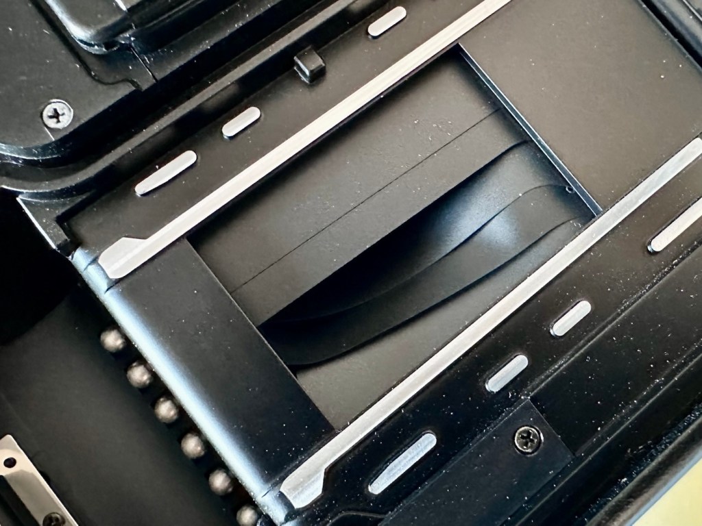
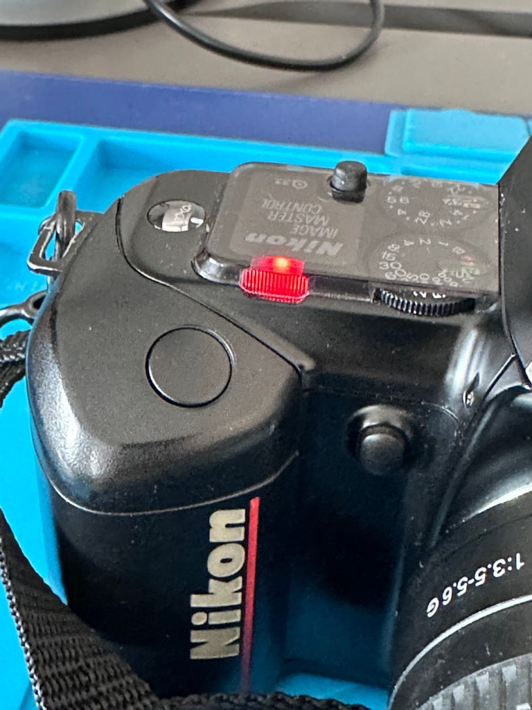
The mirror appears to be in a semi raised position, the battery pack is clean with no signs of contamination and battery leakage, so now seems a good time to put in four AA batteries and slide the battery pack into place and secure it.

Battery pack clean and contamination free

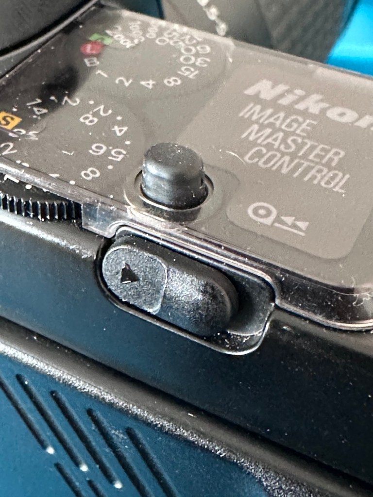
Turn the battery on and the mirror clicks back into its closed position. And here I am, probably 40 or 50 actuations later and I can’t recreate the sellers fault of a sticking mirror. The mode the camera is set in, is indicating long exposure times, maybe this has given the impression of the mirror sticking when in fact it’s just doing what it should relative to the light it is seeing. I need to check in clear daylight, but I’m sure this is part of the issue….if there is one.

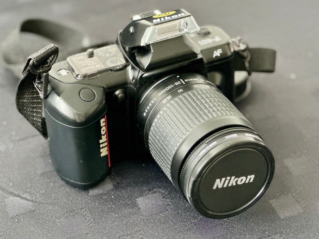
With a 28-100 lens added

I have a 28-100 lens mounted that I use for testing, the autofocus is working really well and all seems good.

However, take a look at the picture below. It contains two photos of the LCD screen on the top of the camera. What do you see in the top photo that would make you think there is an error?

Is that an error?

For the un-informed, those who are not familiar with this camera or its operation, you will instantly see the letter “E” that is commonly known as an error indicator, in later models it is shown as “ERR”. I do believe the seller has possibly mistaken this for an error code, but if you refer to the bottom photo where I have now installed a test film, it becomes clear that the “E” on this camera represents the word “empty”. No film installed, a simple and easy to make mistake. The bottom picture indicates a film is installed and that 4 exposures have been taken.

As these cameras have in the past been known to have a mirror sticking issue, I will replace the mirror bumper felt. It is well known that when the felt has deteriorated to such a level, the felt becomes sticky, and the mirror just sticks to the felt when it opens. It’s an age related issue that is easy to repair. Even though I have not experienced it with this unit, I will replace it as it will probably fail at some point. I will also check the light seals and replace them if I deem this necessary.

Repair:

The light seals do not need replacing. In fact there are only two small spots of light seals on this camera and both are in good condition.

However the bumper seal was showing signs of degradation, so this has been replaced.

The old seal peels out but leaves a sticky residue behind, this has to be removed with some IPA prior to cutting new foam to size and reinstalling. Whilst I was in the lens are I also removed the focussing screen to clean it and remove the old ingrained dust and dirt.

The area within the mirror area is now clean and dust free after I have used a small air blower to get the last of the debris out of the barrel area. Mirrors have been cleaned and polished and the body cap has been put back on the front of the camera to ensure no further dirt or contamination gets in there whilst I work on the outside.

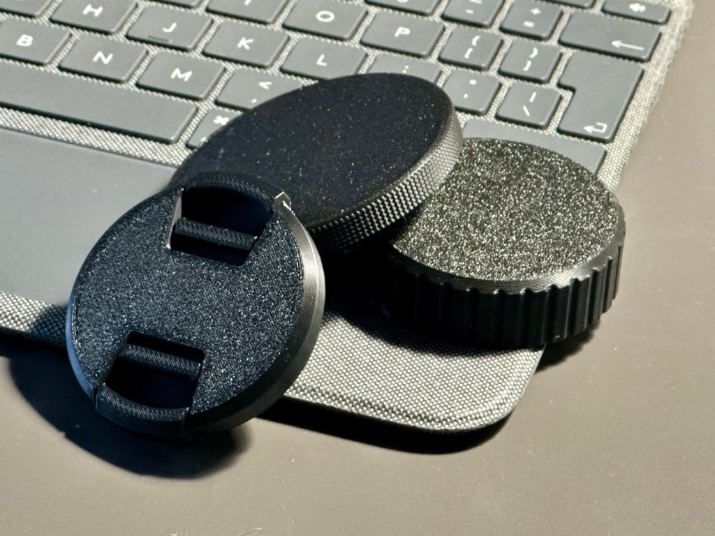
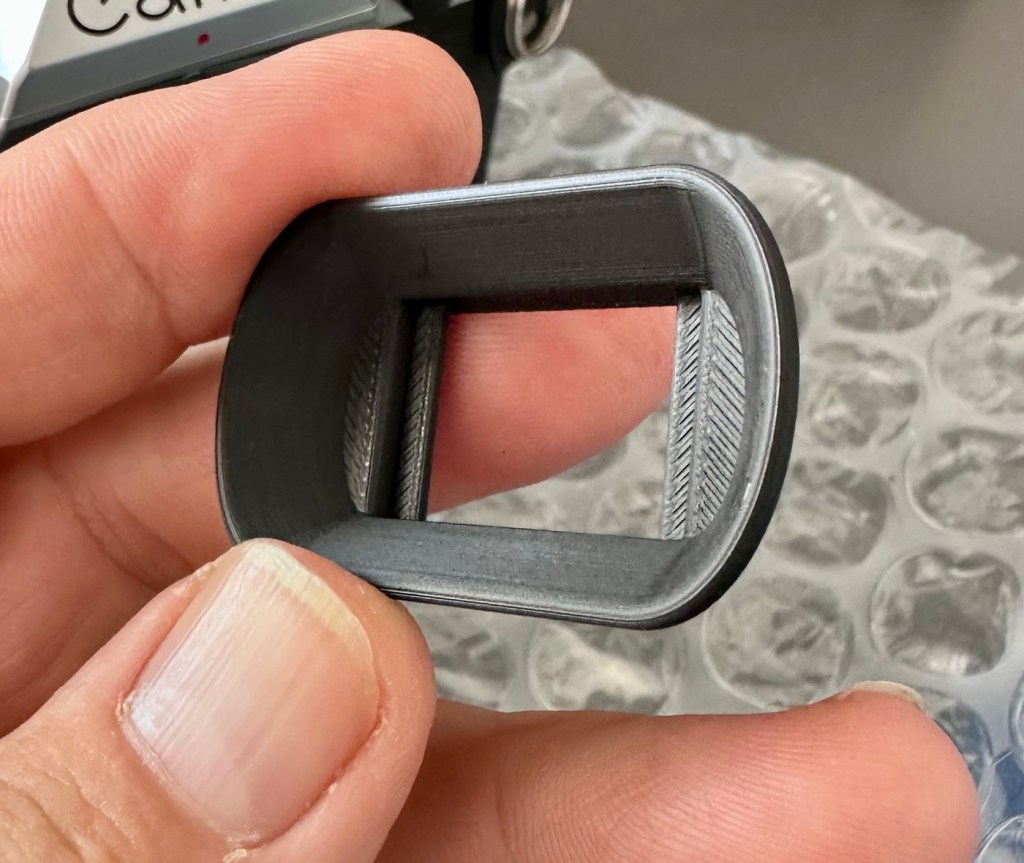
I’ve printed a hot shoe flash cover purely for aesthetic reasons, I’ve also printed a sync cable cover, for similar reasons, but generally just to ensure any open and exposed areas are covered up. It does make it look a lot nicer.

The sync cable cover also helps keep the exterior tidy as well as protecting the connector.

All I need to do now is clean the exterior of the camera where there is some light dust and dirt. When this is done I will use my usual car cockpit polish to finish the camera off.

When that’s done I will do a quick fly through of all the settings to check if they are all functioning as they should.

Result:

The camera has cleaned up very well and looks glorious. All settings are functioning as expected, and there have been no issues with a sticky mirror or any other issues. The camera is just working well and doing exactly what it should be doing.

I’m using a G type lens so I’m restricted on the type of photography I can do, it stays on its lowest aperture (F:32) but that’s perfectly fine In bright sunlight conditions. I need to purchase myself another lens for testing to allow me the use of the full spectrum of apertures on this unit. That said, my lens has performed perfectly on this unit.

As I’ve stated before, this seller is one of my favourite suppliers as his cameras are always in a good condition, he doesn’t like anything unless it’s absolutely A1 perfect, so this is where i benefit as every unit I have purchased from him is perfect in my eyes, and in many cases need very little doing to them to bring them back into a working condition. This is one such unit.

So, I have yet another lovely piece of 90s “Big” tech restored and working perfectly. The next thing I need to do is to put some film through it. I’ll let you all know when I’ve done that.

Thank you for passing by, have a wonderful weekend, I really appreciate your being here.

Take care.

Sometimes, but very rarely, “AI” may just work in your favour.

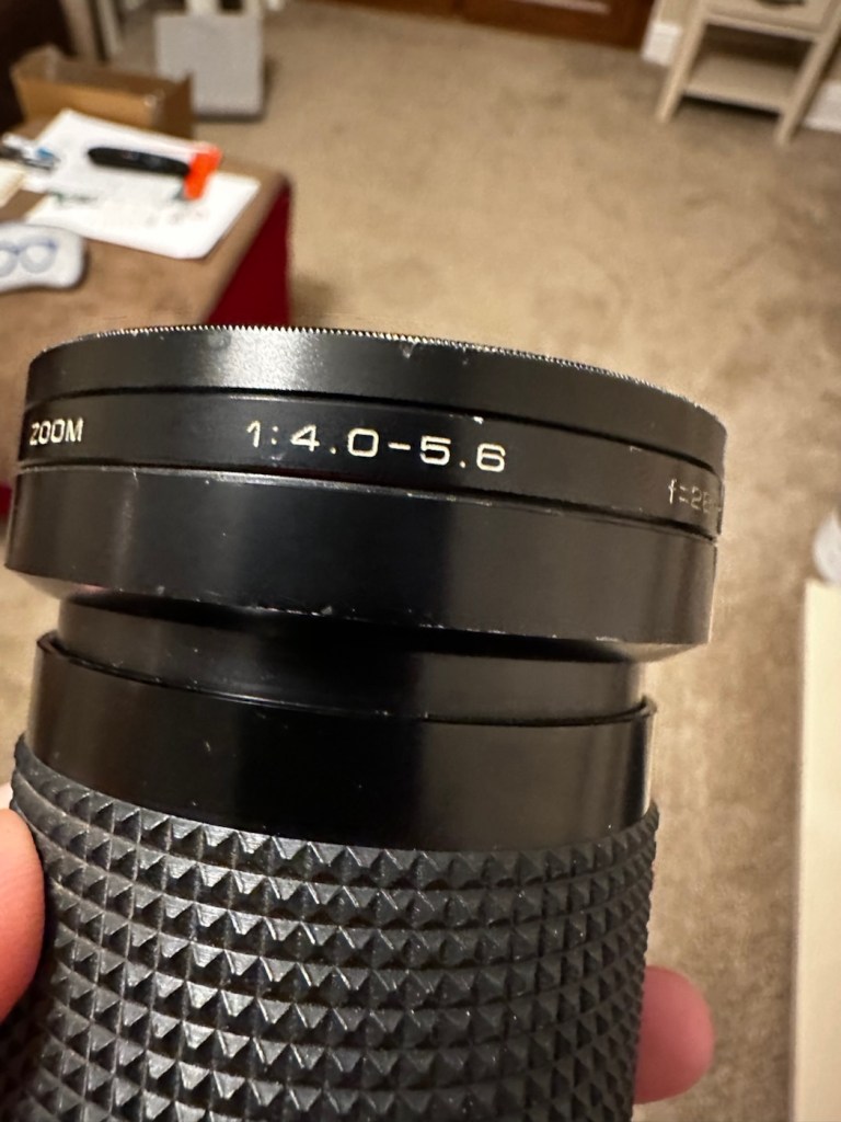
I’m fixing this lens and came across this broken part. But what is it called? Does Chat GPT know the answer? It seems it does.

Please do not for one minute consider this an endorsement for AI, it’s not. I very rarely ever use it, and to be totally honest I keep as far away from it, as i possibly can. The only issue is, is that it gradually sneaks through the back door unannounced in pretty much any application or program that you now use. There is no escaping it really, even here on WP this week I received an invite to start using AI to write my posts and to control their content and SEO compatibility, whatever that is. Straight in the bin it went, no thanks, not interested.

I know my grammar and punctuation leaves a lot to be desired, and sometimes it is very poor, but hey! That’s me and I don’t want to suddenly appear to be a fully functioning and academic genius, as that’s just not me. I’m a Comprehensive educated drop out, that has managed ok thank you, and I don’t need some computer to portray me as something I’m not, or am likely never going to be.

Rant aside, let’s get back to the story that is based around the item in this picture.

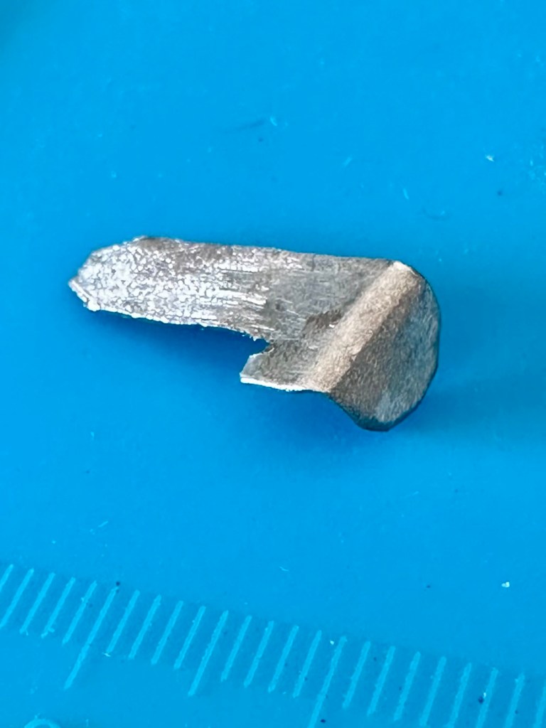
What’s that then?

I’m currently carrying out a repair on a Canon EF 28-200 lens from around the year 2000. Whilst dismantling this lens, the above part became the item of interest as this is a piece that controls the zoom of the lens, hence this lens never really worked due to it’s inability to focus or zoom, and the item above appears to be the guilty party.

It’s broken, that is clearly obvious to see, it’s made of an alloy, possibly aluminium, and is not repairable by soldering due to the immense high temperatures that would be required. I can’t achieve such temperatures as I don’t have the equipment available to do such work. I could try forming something from scratch, that is an option but I don’t really have the time or patience to be honest to spend such time on such a tiny piece of metal. The whole piece is no bigger than 2cms long at its longest point. It really is tiny but essential for the smooth operation of this lens.

This is where the AI help comes in.

Having looked at many repair manuals belonging to Canon, I have an immense list of code numbers but nothing at all explaining what this item is or if there are any still available. I’m kind of lost and at odds as to what I should do.

In desperation, I type something similar to this request into Chat GPT:

“Long angular aluminium piece, working the telephoto element of a Canon EF 28-200 lens”

And this came back as an option:

Bingo – Courtest of Barrell Y Store – Ali express

Wow. That looks familiar!

And it is in-fact the part I am looking for, on the Ali Express site, our friends in China have one left in stock – “Click” that’s purchased and is now on its way to me.

I am now also fully aware of what it actually is, apparently it is called a “Zoom guide pillar, zoom lever, electric brush lever for a Canon 28-200 zoom lens”

Well there you go, it appears AI is good at deciphering the ramblings of a frustrated and confused 60 something. And in this case it did very well. When this arrives I’m going to give it to one of the tool makers at work to get him to make a few copies, I’m even going to see if I can get a few printed out 3D wise to see how the plastic version holds out under the demands of the lens. I don’t foresee any real issues as long as the lens isn’t mistreated in any way.

Well. That’s my major frustration of the week, and my first real face to face involvement with AI.

It can only get better, or can it?

Have a super day. Stay real.

Rollei XF 35 35mm Rangefinder Film Camera 

I’ve just purchased an old Rollei 35 XF rangefinder from around 1974. It doesn’t work, so let’s see if we can get it working again.

What the listing stated:

The Rollei XF 35 is a compact vintage 35mm rangefinder film camera made in Germany, known for its classic design and portability.

This camera is being sold as spares or repairs and does not power on. It has not been tested with film and is not in working condition; functionality of the shutter, meter, and other features has not been confirmed.

Cosmetically, the camera shows typical signs of age and use, but no major damage is visible. Please note this item is intended for parts or restoration and is not guaranteed to function.

Accessories included: wrist strap and lens cap.

EBay

I like these little point and shoots. I’ve always wanted one, and ideally I would like an original 35, but in the meantime I’ll settle for this one. Not working, only £17:00GBP, this was a bargain price for an old camera with a lens that has a superb reputation for having good optics. It’s a bargain basement price for a camera that has a lot of potential if I can get it working again. I have purchased from this supplier before and they are a good bunch of guys and girls, so I don’t believe I am being ripped off in any way. This camera dates from from around 1974.

Here’s a little bit about this camera:

The Rollei XF35 is a small 35mm full frame Rangefinder camera released by Rollei in 1974. The same camera can be rarely found under the brand Voigtlander: in this case it’s called VF135. 

This camera provides only a programmed exposition, with a CDS cell powered by a small 1,35v PX 625 mercury battery. A ring around the lens must be set to the right ASA/DIN value.

The shutter is a small Copal central type one, that also works on relative aperture.

The lens is a Carl Zeiss Sonnar-derivation, built under license by Rollei. It’s a 40mm f2.3, with focus from 1 meter of distance. The viewfinder has a small frame that indicates the f-stop and the speed of the shutter that the program will use. At the center, two small yellow and red circles must overly to obtain focus on the subject.

Shutter speeds go from 1/30 to 1/650s, including bulb mode (only at f2.3). Copal shutter closes up to f16, so Rollei reccomends max 400 ISO/ASA films.

There’s a hot-shoe flash slot and the camera also includes a self-timer (circa 10s of delay). Under bulb mode, this timer can fire the shutter to a speed of circa 5 seconds.

Camerapedia

I’m expecting the camera shortly, so in the meantime I’m off to read the manual and to also look for replacement batteries that replace the now defunct PX625 batteries this camera used to have to maintain a sufficient power supply. When it arrives we can carry out a full assessment.

Assessment:

On arrival it’s a nice tidy little camera, with slight signs of use and that slight mustiness of being in storage for a few years, though I have smelt worse.

It needs a little clean, the strap buckle is a little rusted however that is easily replaced.

Inside, the camera is clean, the winder works and the exposure button works, however the shutter doesn’t fire. This could be one of a couple of issues, the battery inside that appears to be an original PX625 Mercury battery could be below power, and if it is an original this could well be the case. However the light meter is working and this is a welcome bonus, so there is a little life still in the battery that should be 1.35v when at full power.

Light meter is functioning

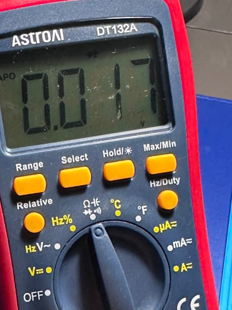
Let’s check this with the multimeter, before purchasing a new battery, and I can confirm the battery power sits at 1.53v?

A fully charged 625A battery

I was mistaken, it’s not an original PX625 it’s actually a 625A alkaline replacement. These alkaline batteries are 1.5v rated against the original that was 1.35v. These batteries are commonly used with these older cameras as a suitable alternative to the original battery. The only issues that are sometimes reported are that the metering can sometimes be off by about +2stops, however some people report no issues at all so it is all a little bit and miss to be honest. I guess it’s all down to trial and error with your own film stock and the camera, B&W film would probably be more forgiving. So, in this case it is not a power issue. We need to then move on to another option.

The other related issue could be sticky blades on the shutter mechanism, and that is more than possible if the camera hasn’t been used in quite a while, the old lubricants dry out over time and the shutter blades get stuck, this means I would have to carry out a service of the shutter mechanism, not a major issue just quite time consuming.

Repair:

I have liberally coated the shutter blades from inside with some isopropyl alcohol as that’s all I had available at the time. This has removed some old black gunk that appears to be old oils of some kind, however the shutter still does not operate when activated, even though all the noises are there to suggest the mechanism is actually working.

I have used a compatible tool to tempt the shutter blades open, this initially worked but they did not fall back into place with any urgency. I suspect there is residue on the opposite side of the shutter blades, so it looks as if this will have to be a full CLA – Clean, lubricate and adjust, requiring a partial disassembly of the camera.

Boy I wasn’t wrong, this is probably the deepest I have gone into a camera for quite a while, this camera really does have to be dismantled. These cameras have always been renowned for having issues deep into the cameras workings, it’s probably what has gained them a poor reputation, somewhat unfairly, but not everyone is prepared to dismantle a camera at these prices, when they can just chuck it and get a new one. However that’s not what I do here.

Let’s stop the chat and get on with it.

So we need to get inside, and the best plan of attack is from the front through the lens turret, so first thing we do is remove a retaining ring on the lens. This allows us access to the insert that controls the ASA, and where the CDS cell is located. Remove with caution as there are small wires present.

Three screws under the ASA/CDS module then allow you to remove the focus ring where there is a small brass plate. This is removed and then the rest of the barrel loosens, but cannot be removed….strange.

At this point I had to do a little research and source the maintenance manual and refer to it to see what I had to do next.

Maintenance manual courtesy of Rollei

After reviewing the manual it appears there are another four screws requiring removal before we can access any deeper, however these are situated under the camera “Skin” and this needs to be peeled back slightly to access.

With these four screws removed, you now have to remove both the top and bottom parts of the camera, five more screws to allow the front plate and lens to be removed.

Base of camera removed exposing winder workings

With the lens plate now movable, again I carefully move it aside being wary that there are also wires here, and not a lot of room for manoeuvring. A slight twist of the brass aperture control plate and it can then be removed. The plate below this, with the three brass dots, just clips out and exposes the thin shutter blades below.

Just looking at the shutter blades I can see there is a small link missing, this was sitting loosely to one side, it could have come off as I was dismantling the blades, who knows. Carefully put to one side the blades are placed individually in preparation for a clean. Lastly the bottom plate of the shutter mechanism, lifts out and beyond this point is the camera back, we have just a hole as the whole shutter and lens mechanism has now been removed.

All parts removed have now been cleaned with an IPA solution to remove any grease and dirt, and there was quite a lot of both. These have all been put to one side and will be cleaned once more prior to reassembly.

A period of time was spent just watching and observing whilst I continued to prime the camera and fire the mechanism to see if I could see anything obvious that was of concern. After a while I could see the issue, there is a small flywheel that was not moving, and as a result the connected shutter mechanism could not move.

The flywheel controls two parts of this mechanism. Firstly the shutter mechanism to move and work the shutter blades, and secondly there is a small brass pin at the top that also moves relative to the aperture setting, if this is in the wrong position, the shutter fires but will not close, this wheel is where the issue lies.

Using some IPA I get into the gearing from the base area, and give all the gears that I can access a good clean, I activate the camera numerous times to get as much grease and dirt away from the workings as possible.

Then using a very fine camera oil, very sparingly, literally a drop on top of a needle applicator, I place oil onto the cogs paying special attention to the offending fly wheel.

I have three shutter blades that are super thin and delicate that need a final clean, dry and a dry wipe prior to reinstalling. I get this done and then put both links in place, after installing the blades in the correct order.

Shutter blade reinstalled, with both links
A small video showing the shutter working

The re installation of all other parts is just a reverse action of how they were taken out, each part was cleaned as it was put back, so in theory the camera is an awful lot cleaner and free of contamination than it was a while ago. Before I put the lens plate back on the camera I check the shutter’s operation and it is all fine. Just a final calibration of the aperture settings, a check of the focus range, and just ensuring all wires are routed sufficiently, and the lens plate is ready to attach to the rest of the camera. This done, the base and top fascia plates are attached after first cleaning the focus window and light meter window. The camera is now fully assembled, it now just needs the camera “Skin” to be re glued where it was earlier removed for access.

Reassembled and just needs gluing

The skin is now glued into place.

Now I’m outside the camera I’m just going to touch up some of the scuffed areas with some permanent marker, it’s not worth stripping down, priming and repainting, to be honest I’m quite happy just doing a touch up of the scuffed areas and that is what I have done. Once it gets a clean and polish it will appear much improved, compared to when the pen is first applied, it will blend in.

Before and after pen applications

I’ve taken the old strap buckle off as that was rusted, I’ve just used the original strap ring to connect to the camera lug, I think it looks good. I’ve also added a cover for the hot shoe connector that I’ve printed off on the 3D printer.

Original ring

And that completes the repair, the last thing to do is get this camera cleaned and polished.

Result:

With a good clean and polish, this little handheld has come up looking superb.

With all the extra touches, we now have a superb working, resurrected camera that was heading for landfill. This has taken a lot of time and patience, something I don’t have a great deal of if I’m honest, but I was determined to get this project finished. And it is. It looks good, works good and has years of life left in it. Currently sitting at 52 years old, it has a long life ahead of it.

This camera probably rates as one of the most fulfilling and pleasing projects I have ever started upon and completed. It’s been a very delicate and time consuming job, and that I will not deny. It’s only a cheap low cost camera but it’s taught me a great deal. It’s the first complex project I have undertaken, in my new workspace, I don’t think I would have been able to complete it with my old set up. It’s been an achievement, one I am considerably proud of, an occasion when once again, it doesn’t matter how old you are, you can still learn a lot. A big positive for me.

Anyway, enough about me.

Thank you most sincerely for passing by and giving me your time. It really is, very much appreciated.
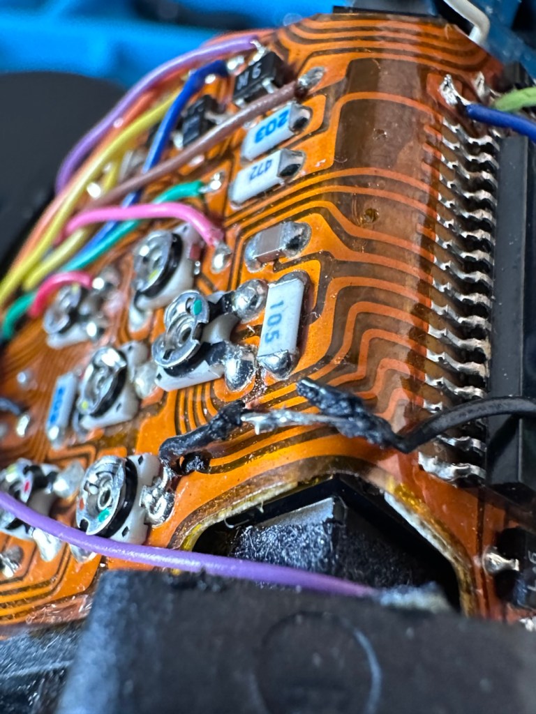
Ilford Sportsman 35mm camera

I’ve been asked to give a little service to a friends old 35mm camera that he’s inherited. Mainly cleaning and making good. An old camera that deserves to maintain its originality.
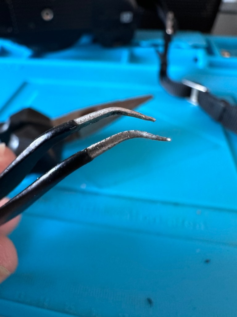
I received this text message tonight from my nephew:

Hi, my mate “T”, has got an old camera from his sister, from a old antique store, he dunno a lot about it and was wondering if you did and if you’d have a look at it and see if it was in working order as he can’t figure much out about it, no worries if not tho 👍

Family

Now, I love these random out of the blue messages, to me it just says people have a trust in what I do, and I like that. And how can I turn down a request such as this. I’ve jumped on to it and said I’d give it a service and get it checked over and up and running, no cost, I just want to feature it within my blog site. The owner is also a youngster, just starting out in photography and has a thirst for knowledge of the traditional side of business, and wants to find out more about the old ways and how the trade used to operate. He wants to shoot film, and process it, and produce his own prints. I can help him do that. And I look forward to passing that knowledge on. In the meantime, this is the camera we are looking at, and wouldn’t it be just great to get it working and use it to get those results under tuition, that he wants to achieve.

This camera is really a rebadged Dacora Dignette produced in Western Germany for Ilford Uk.

Here’s a little history regarding the Ilford Sportsman camera range:

As the desire to own a 35mm camera blossomed within popular amateur photography during the latter 1950s, in part prompted by the more economical production of projectable colour transparencies on 35mm instead of roll film, Ilford Ltd must have been concerned that they did not have their own range of such cameras.

Kodak was importing their 35mm Retina/Retinette range from Kodak A.G. in Stuttgart, a factory they purchased in 1931, (originally the Nagel Camerawerks).

To provide a suitable ‘popularly priced’ 35mm camera, Ilford entered into an agreement with Herr Dangelmaier of the Dacora Kamerawerk, Reutlingen, near Stuttgart, (West) Germany. Dacora produced a simple 35mm camera, the Dacora Dignette, but rebadged it as an Ilford Sportsman for sale in the UK.

Ilford’s Sportsman cameras were a range of viewfinder- and rangefinder-cameras, made for Ilford in Germany by Dacora; the first was introduced in 1957. They were a cheaper alternative to the Kodak Retina and Retinette series for the newly-popular 35mm format at the time. The Sportsman cameras were rebadged versions of Dacora models, including the Dacora Dignette. There were a variety of shutters fitted, including Vario and Prontor mechanisms, housing a selection of lenses such as the Dacora Dignar, Steinheil Cassar and Isco Color-Isconar. The range included basic models, with the Vario shutter and Dacora lens, through fitted meters to sophisticated rangefinder cameras with light meter, Prontor 500LK shutter and Cassar lens.

There were five body styles; the last (Mk.5) introduced c.1967.

Wikipedia/photomemorabilia.co.uk

This version dates from 1957 and is one of the later issued Mk1 versions of that year. It has the Vario shutter mechanism and the Dacora-Dignar lens. The badging indicates that this is a latter 1957 produced variant. The very early versions had the “Ilford” badge printed on the camera leatherette and I suspect this would have rubbed off due to hand positioning whilst photos were being taken. This is probably why the white badge on this variant was then applied. This camera retailed in 1957 at the princely sum of £13.87GBP.
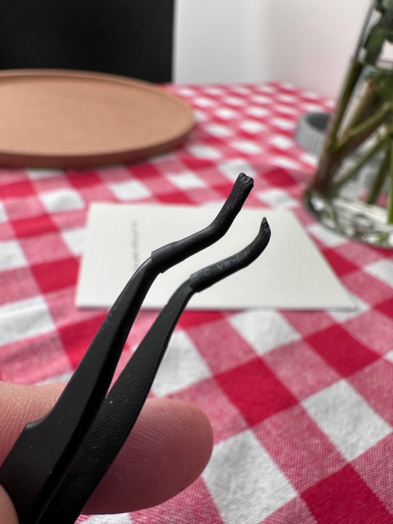
I am now in possession of the original instructions that I will download and pass on to the owner, they are extremely basic instructions, befitting of the year of production.

Front page of instruction manual

Assessment:

The camera is in an overall good condition in an original Ilford leather case and I think this alone has helped keep the camera in good cosmetic condition. It winds fine, it shoots with a little bit of stickiness, but I believe this is on the exposure button only. The aperture leaves stick a little and respond slowly when you leave the shutter on a time exposure and move it through the whole range from f:3.5 to f:16. The focus ring seems to operate smoothly, and shutter speeds of B, 25, 50 and 200 seem to work, but occasionally stick. I suspect the shutter and its aperture leafs are dirty and are sticking, they probably need a clean.

Now I’m not going to do too much to this camera and want it to retain its old character. The leatherette on a couple of parts of the body has lifted, I will probably leave this as it is, I will dismantle the lens turret as there is a general fog in the lens that I suspect may be fungus. I will give the whole unit a good clean and polish. There is a slight break in the leather strap, I shall repair this so as it doesn’t break. There really is nothing of concern that I can see that should be of detriment to the working of this camera. It just needs a clean, and that’s what it will get as I really want to maintain the character of this camera.

Repair:

To get to the lens and shutter area we have to start dismantling the lens turret, that starts with removing four of the tiniest screws you will ever find.
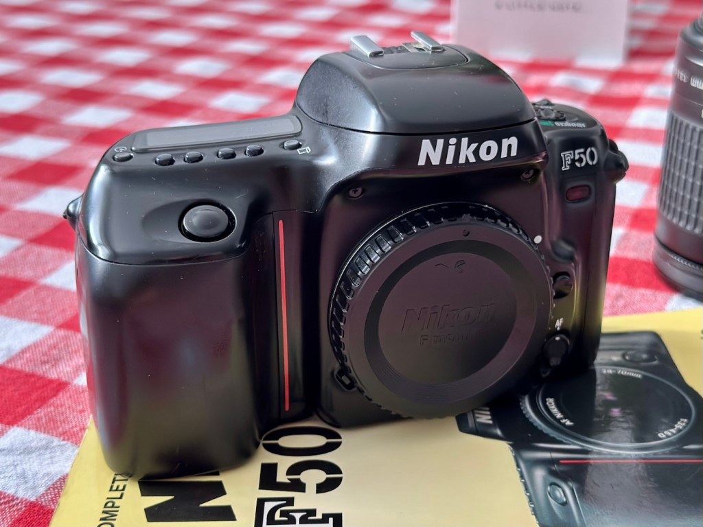
We now unscrew the first element, the outer one, and it’s clear to see that there is fungal scarring of the element.
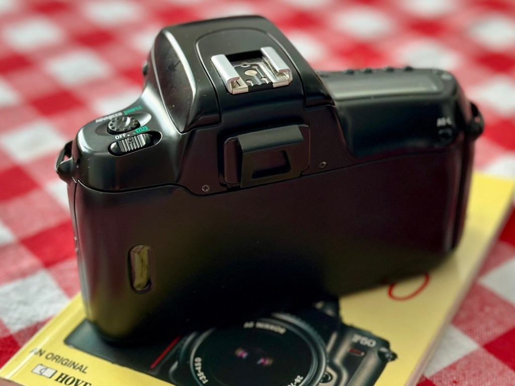
Fungal scarring evident

Next we unscrew the next part of the lens barrel that gives me access to the inner lens element.

We can now reach in and delicately remove the inner element

Removal of the inner element

We now expose the shutter blades and underneath these we find the aperture blades.

I start by giving these sections a clean with a a little “lighter fuel” to remove the old grease and oily deposits. With the shutter blades I clean them very carefully, let them dry a little and then fire the shutter a few times, I blow off any build up and do the process again until I’m satisfied they are free from any contaminants. Now putting the shutter on “B” setting, I open the lens and do the same with the aperture blades opening and closing them manually using the same process as with the shutter blades. Happy with how this has gone I now head onto the elements.

Using a mix of pure water and peroxide I use a small bud to coat both sides of the inner element to give it a clean, it is very dirty, no fungus on this element though, just years of dirt and grime.

Inner element was very dirty

The outer element was a different story, it had such bad fungus that the edges of the element had been etched by the fungus, as it had been there so long. I don’t think it will be too much of an issue through as a lot of it was removed. Below are two photos before and after, the after looks quite a bit better and when it was dried and polished it did look considerably better.
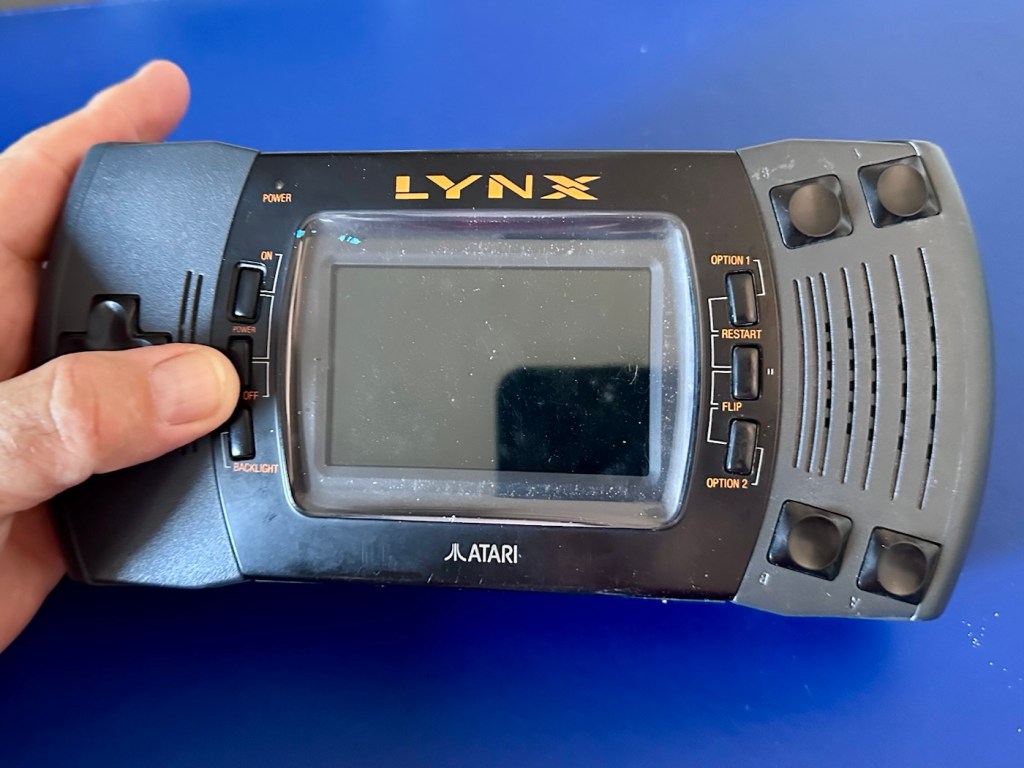
Once cleaned I rinsed the elements off and dried them using a lint free cloth. A good blow with some air dispersed any loose dust or fluff, prior to reassembly.

Reassembly was simple and without issue, I cleaned as I went along replacing any grease and oil with fresh lubricant (sparingly of course).

Reassembled and ready for cleaning

Cleaning wise I’ve used IPA, detailing polish, cocktail sticks (to get into the nooks and crannies) and good old elbow grease. It’s looking good.
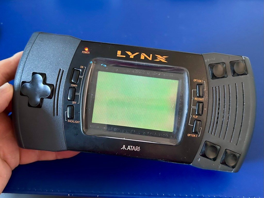
Leather strap repair

I’ve repaired the broken strap by just removing the damaged part and creating a new strap loop, it looks ok, but I’m working with a strap that’s almost 69 years old, very thin, and has seen better days, but it looks okay. There are loose bits on the case where the leather stitching has deteriorated, however leather work is not my forte, so I will be leaving this alone, letting it maintain its old appearance and patina if you like.
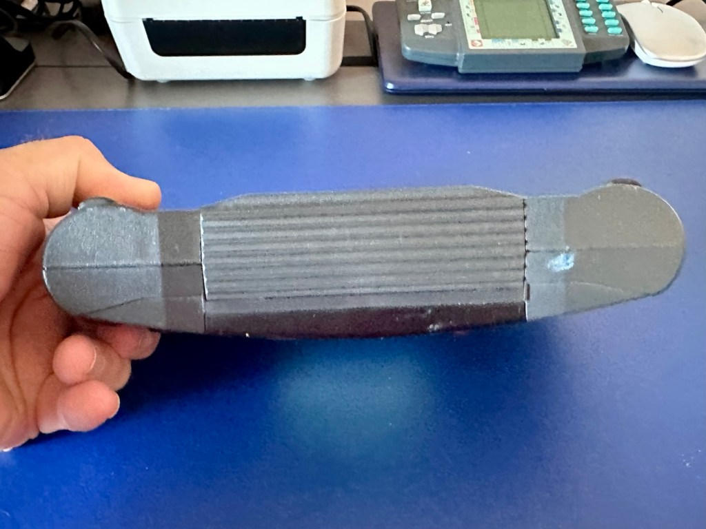
Result:

The result is that I have been able to maintain the original appearance of this camera, only carrying out a sympathetic maintenance regime, allowing the camera to be used as it should, but maintaining its age and individual characteristics.

That case with repaired strap

It’s been nice to just tidy up a camera and give it some attention, TLC if you like. These cameras are remarkably easy to maintain and operate, I’m sure a roll of film through it will give some superb results. The viewfinder is so clear now, the lens is clean and the shutter, aperture, and all buttons and levers are working just fine. It’s been a pleasure to work on this camera, and I sincerely hope that my friend is happy with the outcome. One thing you really struggle with though is the old musty smells these cameras carry with them. If I had a solution I could use to negate these aromas I’d probably be a rich man, or at least my wife would probably forgive for once, for bringing these aromas into the house.

Oh well, you can’t win them all.

Thank you for passing by, it’s always very much appreciated.