Gameboy Advance

Another one of Nintendos mass produced hand held gaming systems has arrived, with audio issues. It’s a Gameboy Advance, with no sound,so let’s try to fix it.

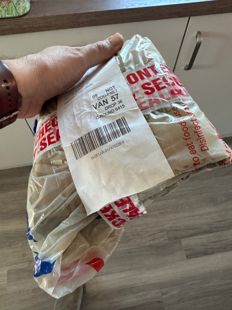
Here’s what the listing stated:

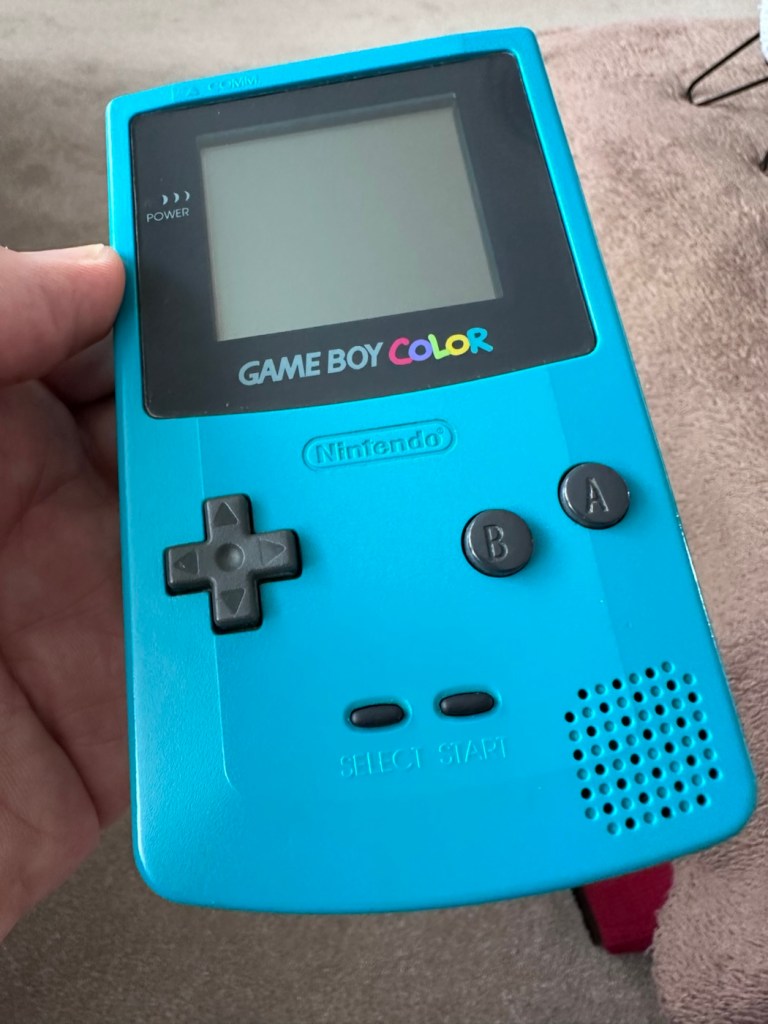
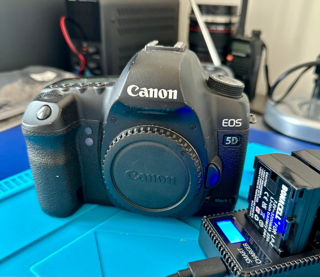
Gameboy advance console, complete with battery cover, all buttons works and powers on but no sound, has marks on screen and a few marks on shell and scuffs/indentations.

Photos of exact item you will recieve, FAULTY Uk buyers only. Has cover missing that the power light shines through on

EBay

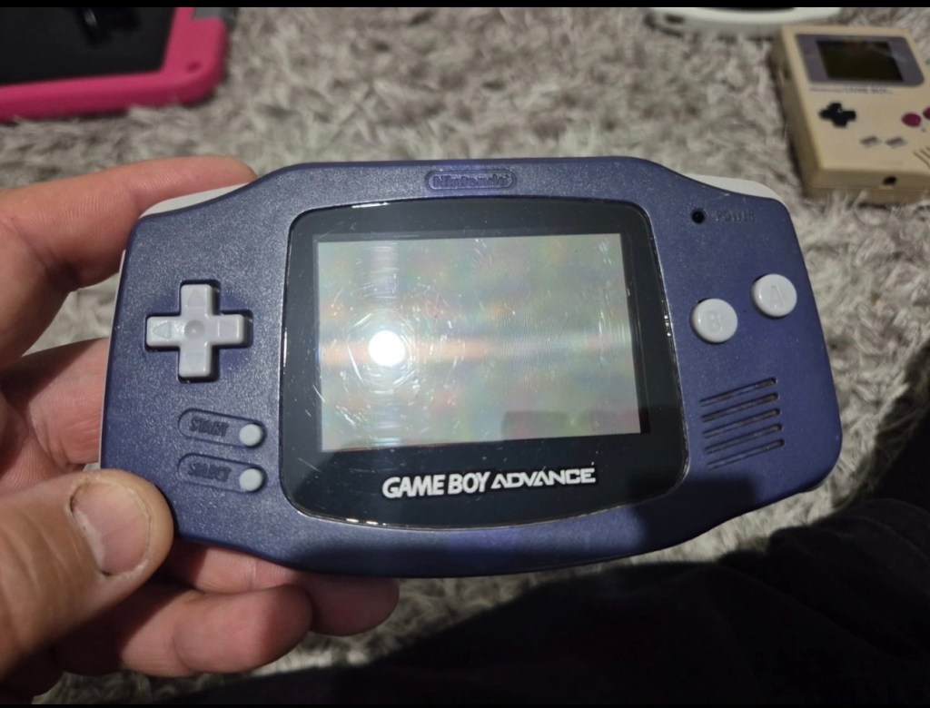
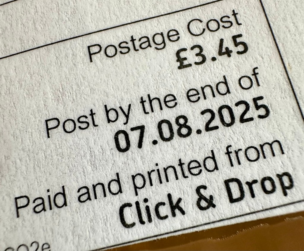
I’ve purchased this as another addition to my collection of handheld retro gaming consoles. As usual it dosen’t work, and that sometimes keeps the cost down a little. This one has cost me £24:00GBP and I’m happy that that is a fair price for one of these units. Here’s a little about the GBA:

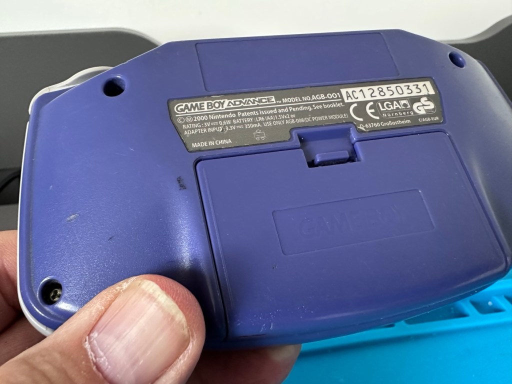
The Game Boy Advance (GBA) is a 32-bit handheld game console, manufactured by Nintendo, which was released in Japan on March 21, 2001, and to international markets that June. It was later released in mainland China in 2004, under the name iQue Game Boy Advance. Compared to the Game Boy Color it succeeded, the console offered a significantly more powerful ARM7 processor and improved graphics, while retaining backward compatibility with games initially developed for its predecessor.

The GBA is part of the sixth generation of video game consoles, competing against Nokia’s N-Gageand Bandai’s Japan-only WonderSwan. The original model was followed in 2003 by the Game Boy Advance SP, a redesigned model with a frontlitscreen and clamshell form factor. A newer revisionof the SP with a backlit screen was released in 2005. A miniaturized redesign, the Game Boy Micro, was released in September 2005.

By June 2010, the Game Boy Advance series including revisions, had sold 81.51 million units worldwide, massively outselling its competitors. Its successor, the Nintendo DS, launched in November 2004, was backward compatible with GBA games. GBA sales ended by 2010 after over nine years.

In 2008, the GBA was still Nintendo’s predominant handheld console in terms of market presence and global installed base. It was only in late October 2008 that Nintendo announced that the Nintendo DS had officially surpassed the GBA worldwide in sales. This milestone consolidated the definitive global leadership transition between generations,[13]although in specific markets, such as the United States, the GBA was only surpassed by the Nintendo DS in sales in late 2009.

Wikipedia

Now just to reiterate. These units are now 25 years old, there were in excess of 81 Million of these units produced and they still command a good price today. Just consider how many of those units have been sent back into landfill, the figure is probably immense. But then again we produce many items en masse, and we have been just chucking stuff away for years. The figures must be mad.

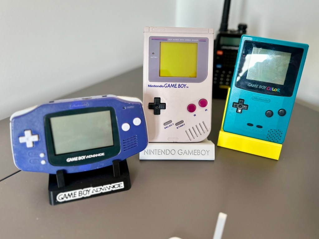
Except for this one. It will be repaired, cherished and reused. And displayed for all to see.

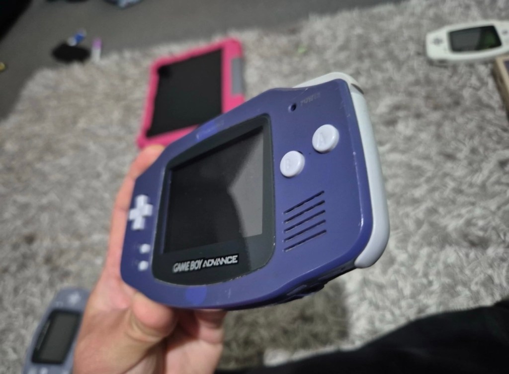
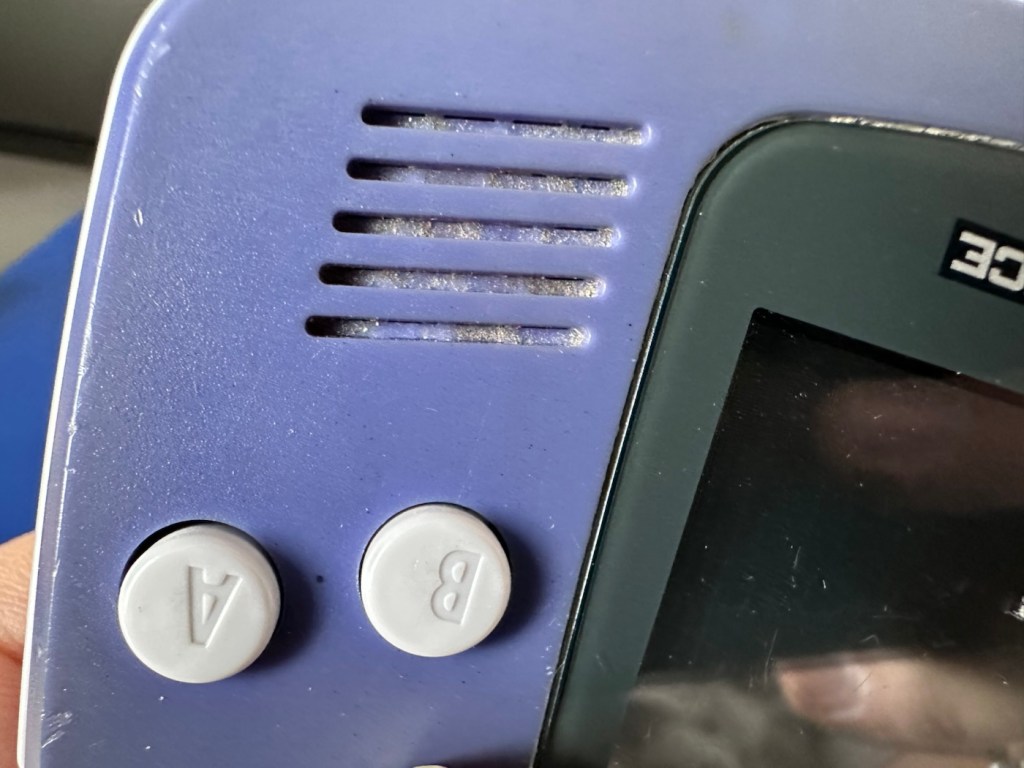
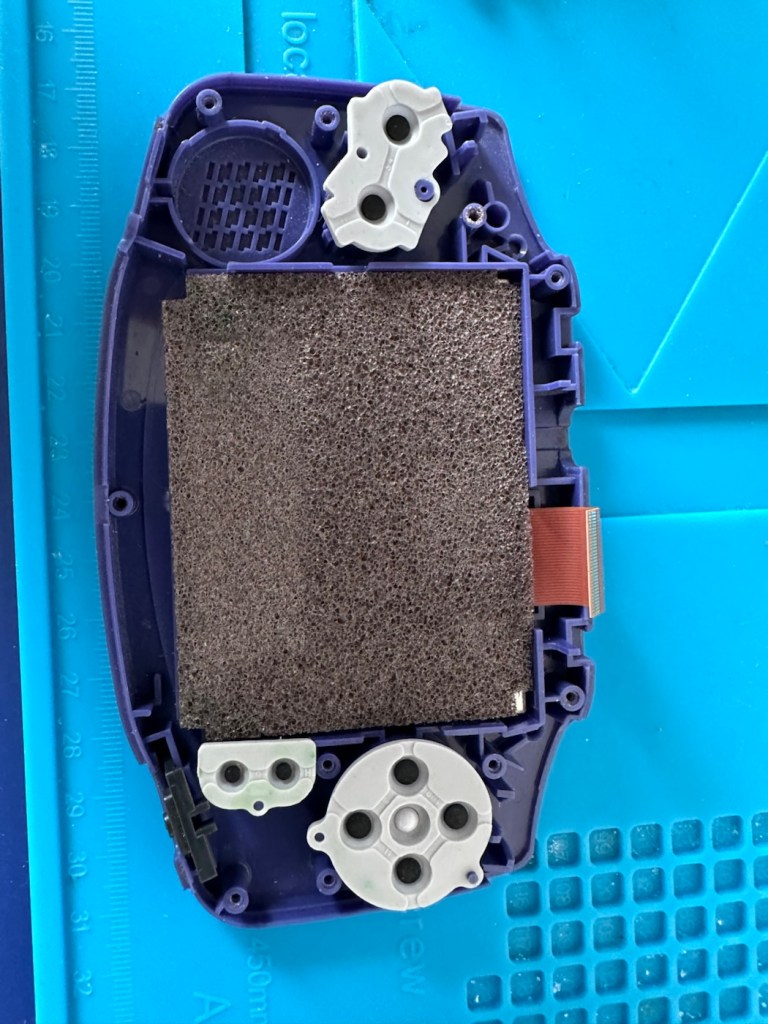
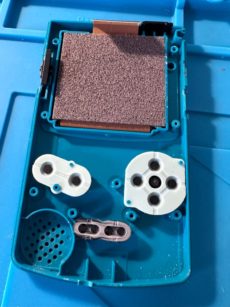
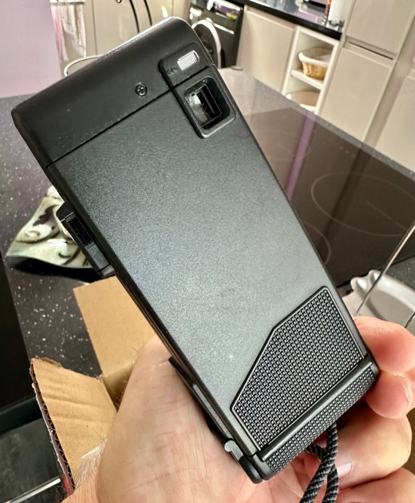
This one has been advertised as having no sound. Just from viewing the sellers photos you can see there is an awful lot of staining around the speaker grill area, maybe some liquid has been spilled here and the speaker is damaged, or maybe the audio capacitor inside has blown. These are usually the two main culprits, but you never know it could be for some other totally different reason. Let’s not make assumptions, let’s see what turns up.

Assessment:

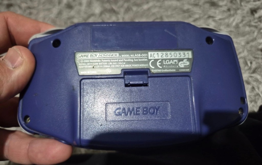
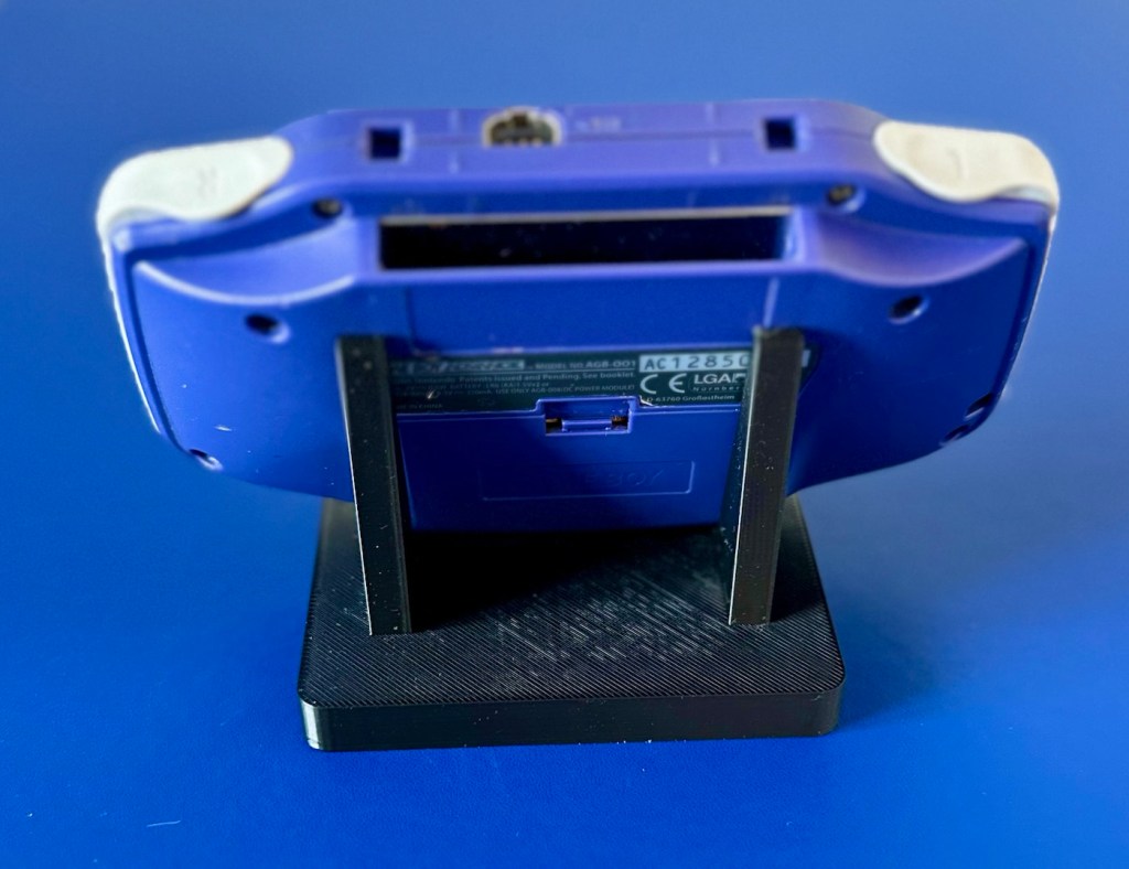
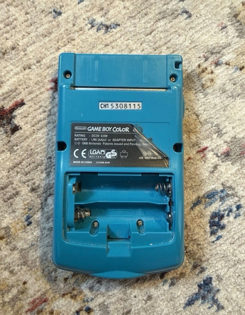
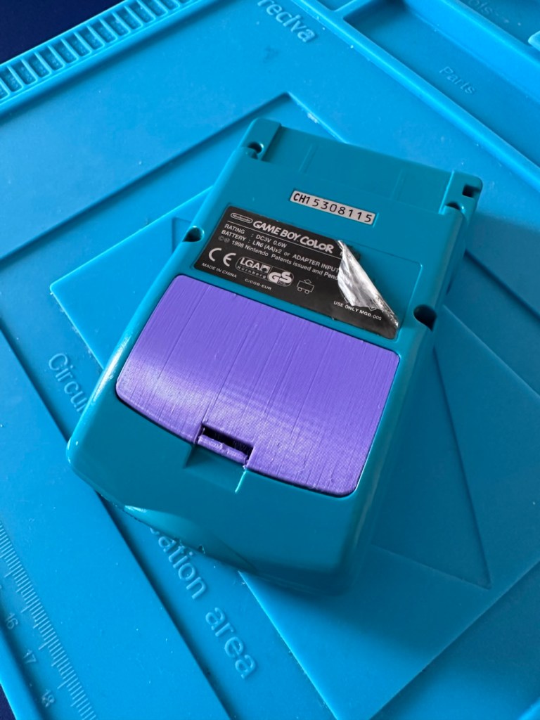
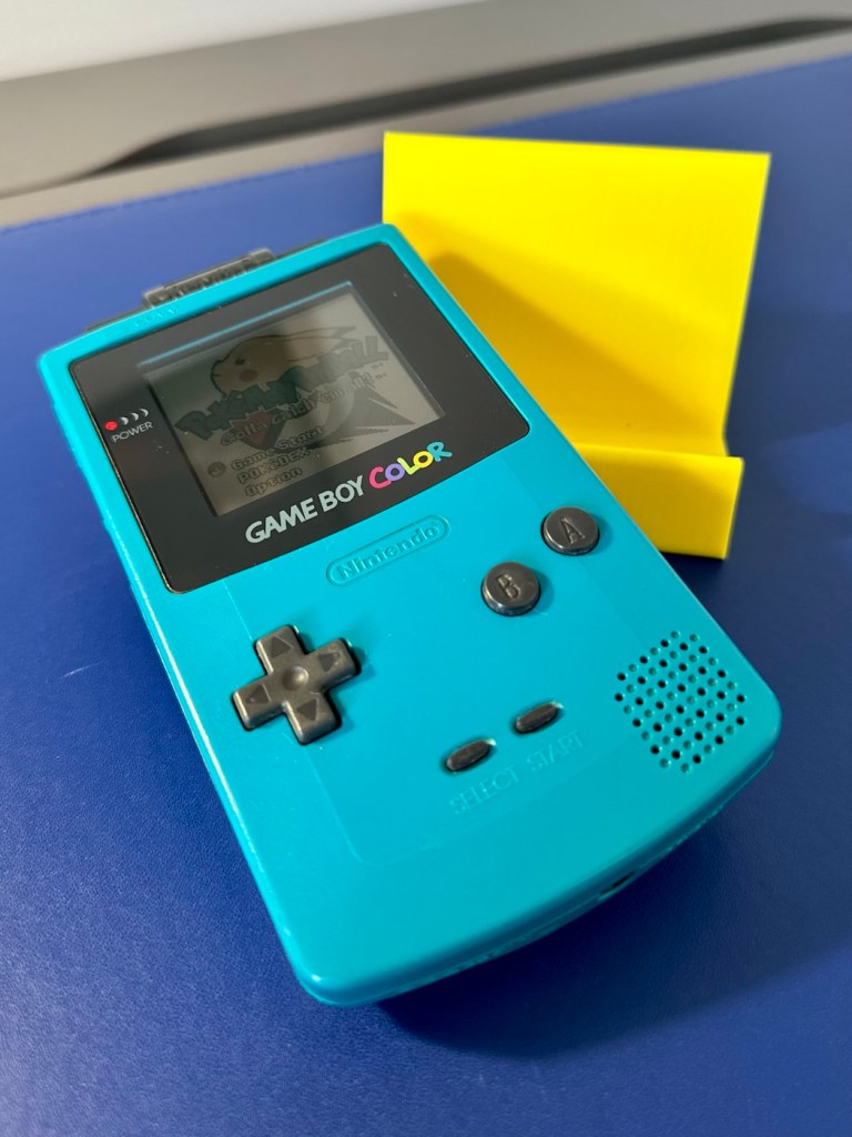
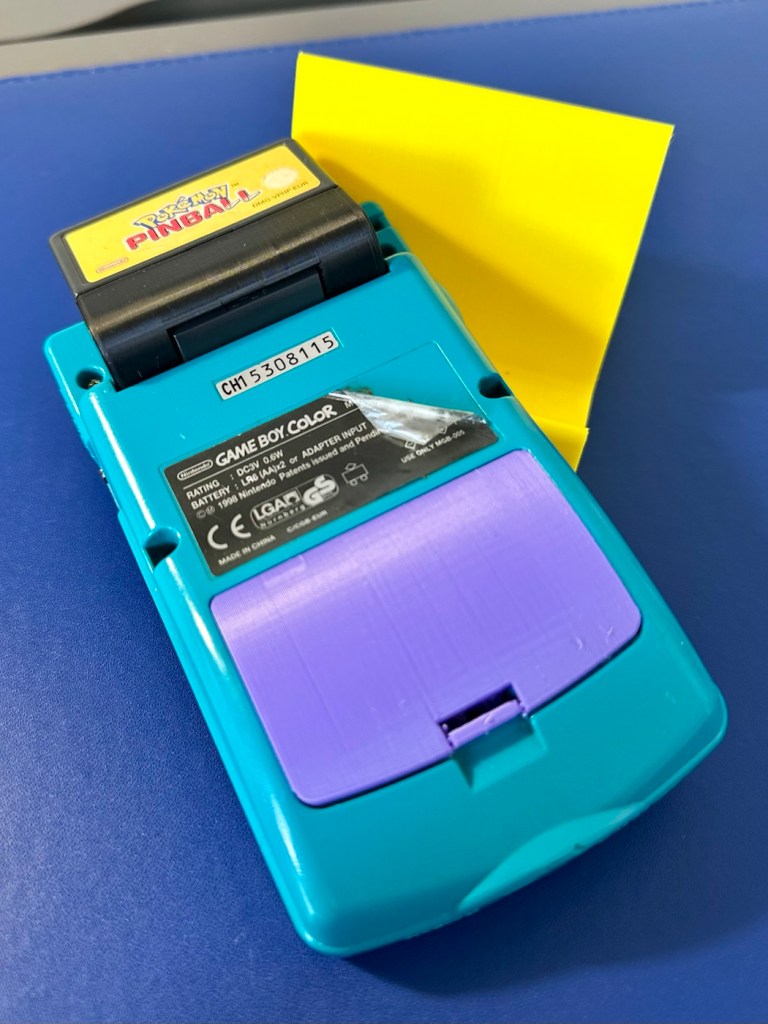
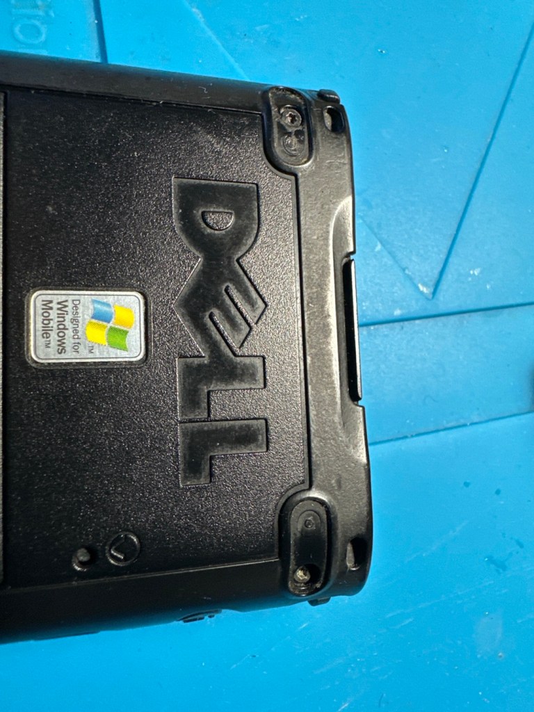
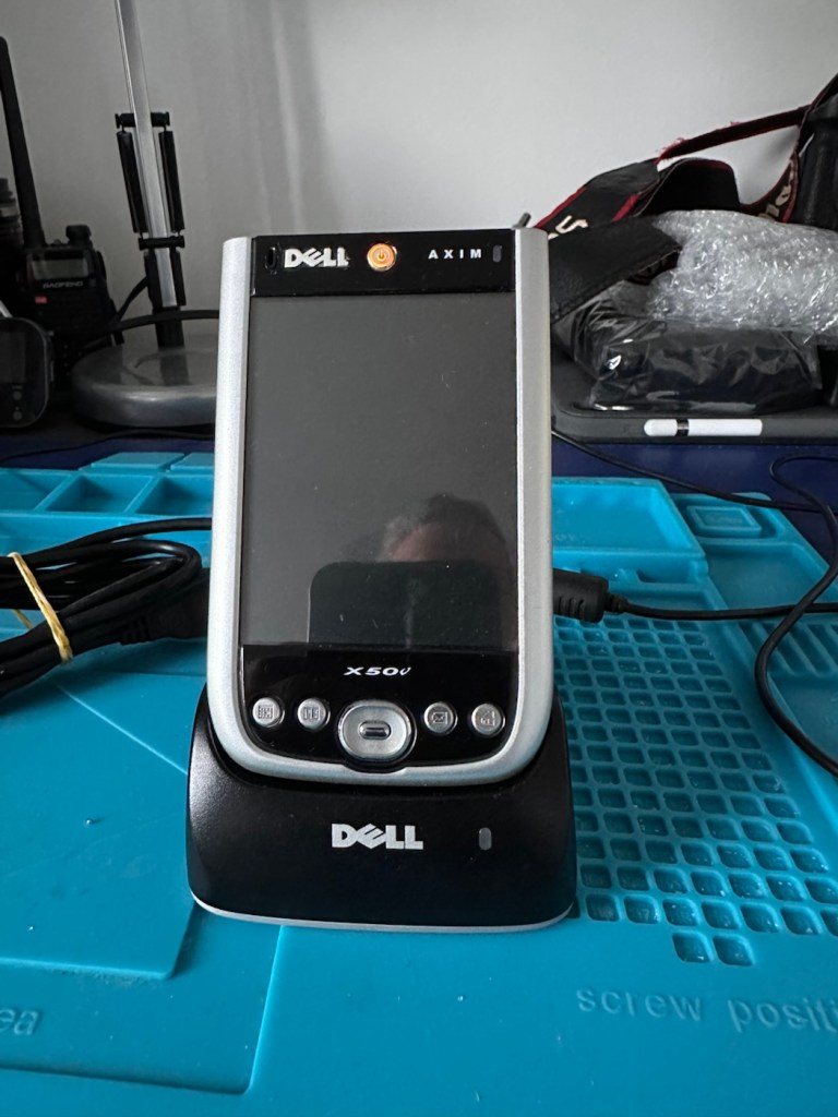
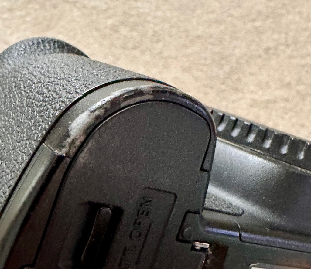
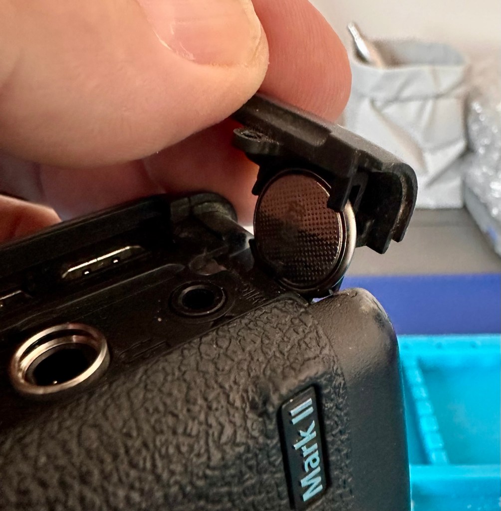
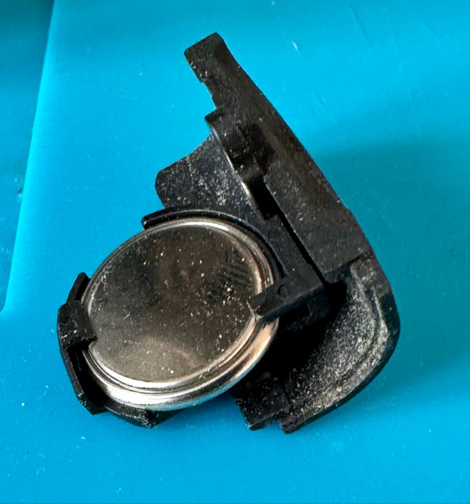
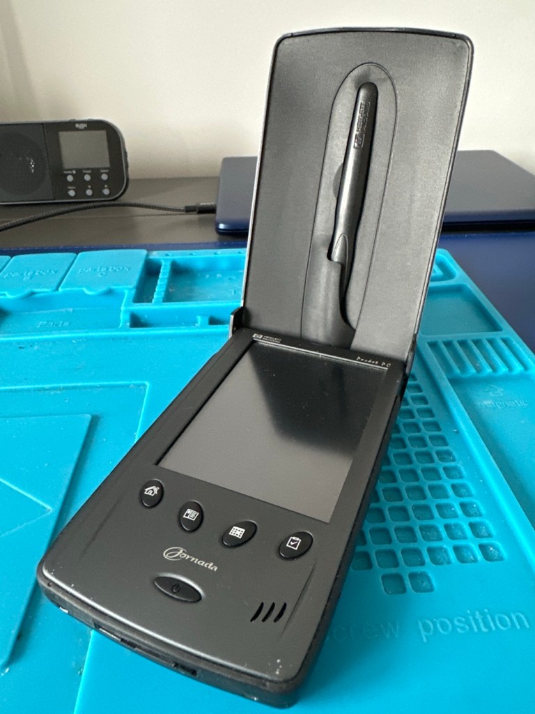
The unit has arrived all in one piece. The battery cover is in place, a little loose at the clip but I might be able to strengthen by heating and gently manipulating it.

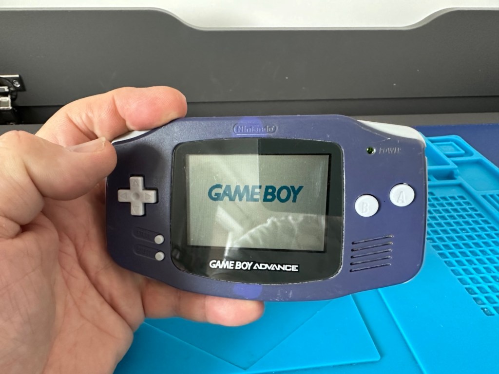
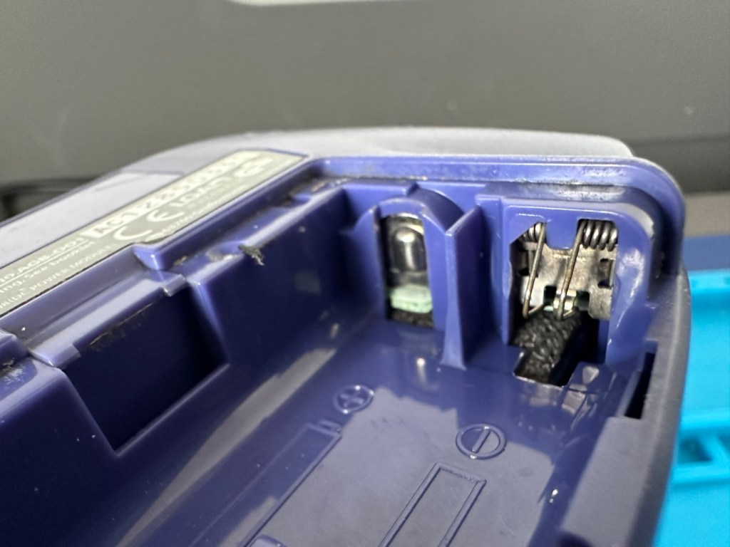
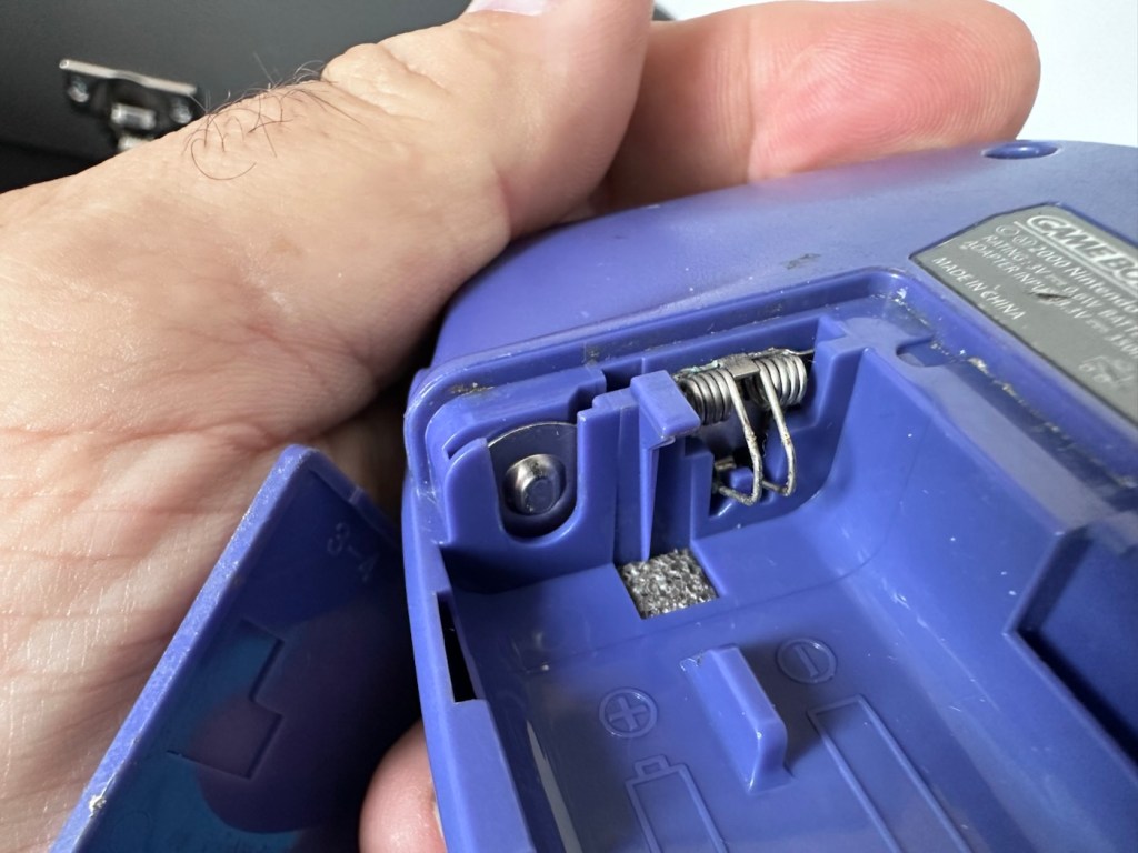
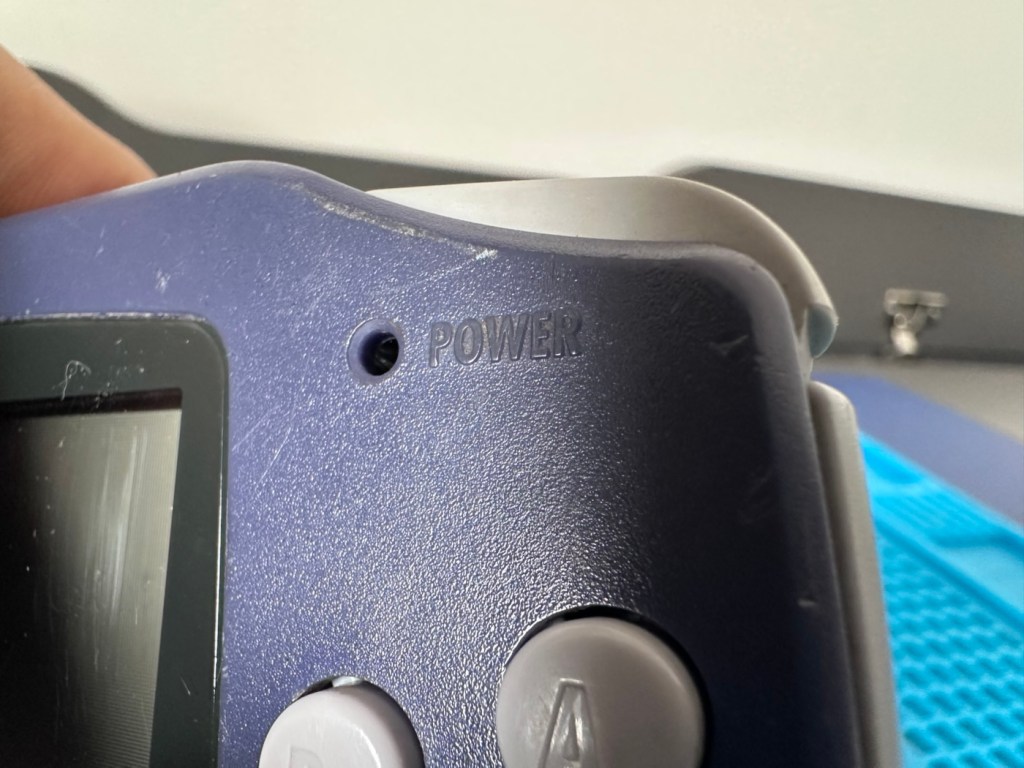
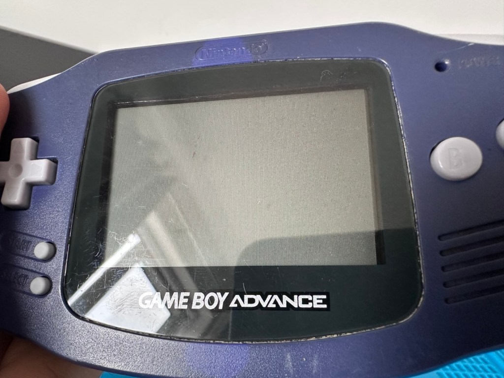
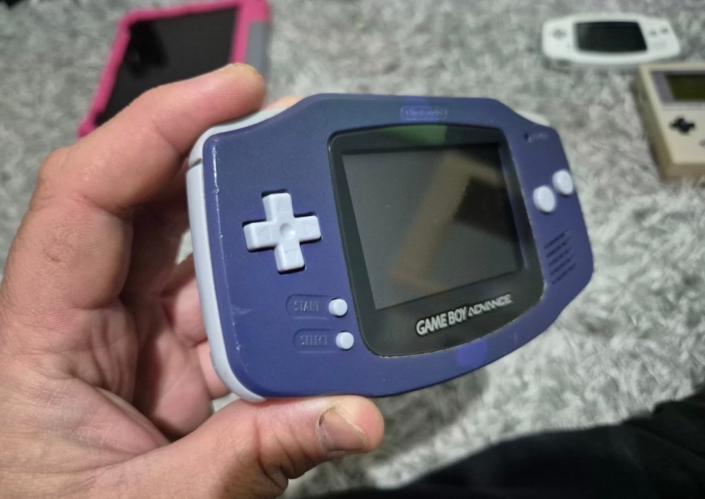
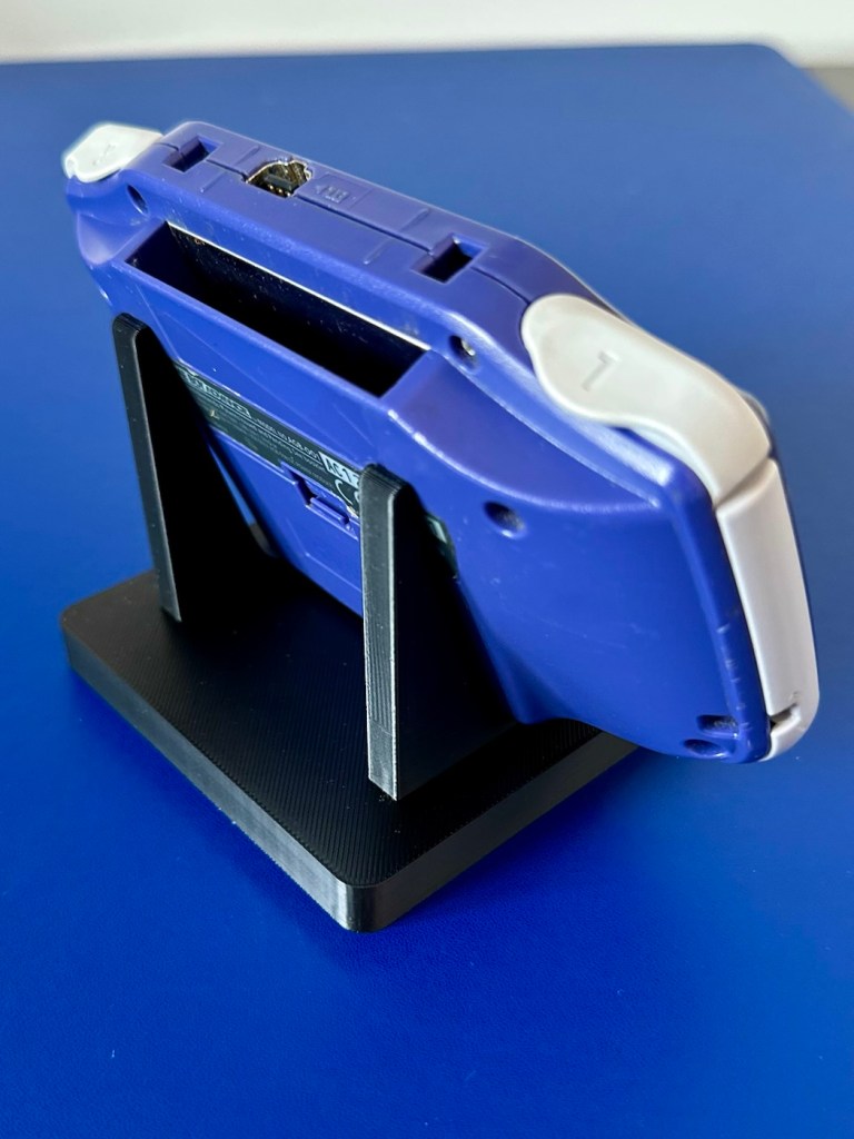
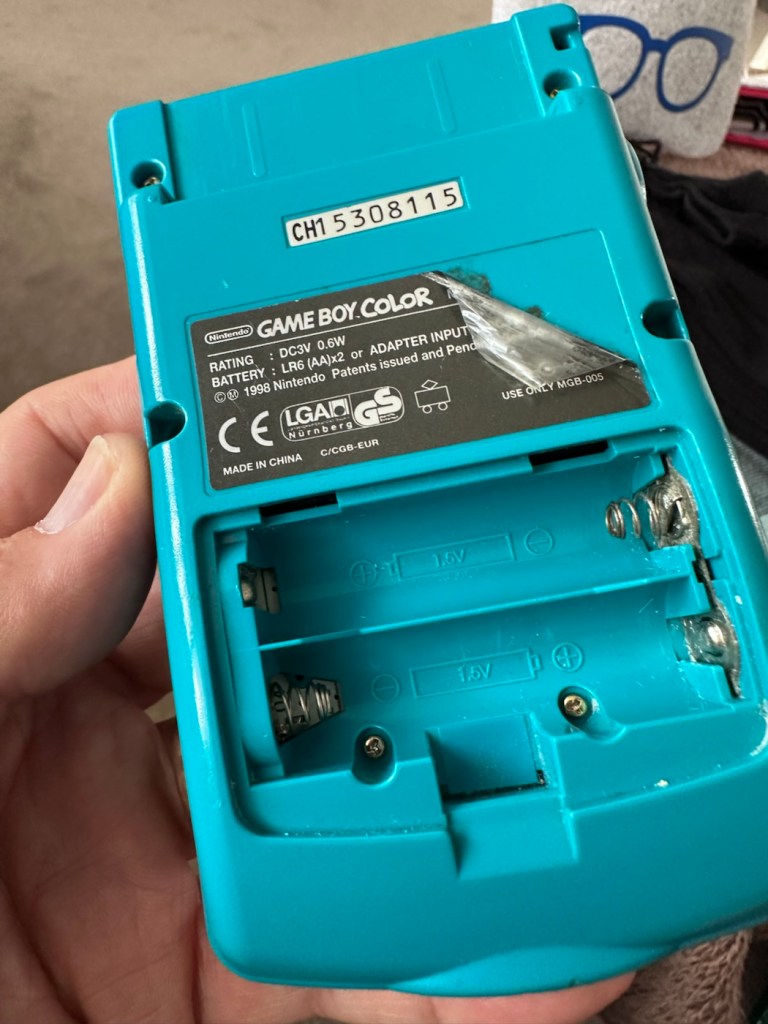
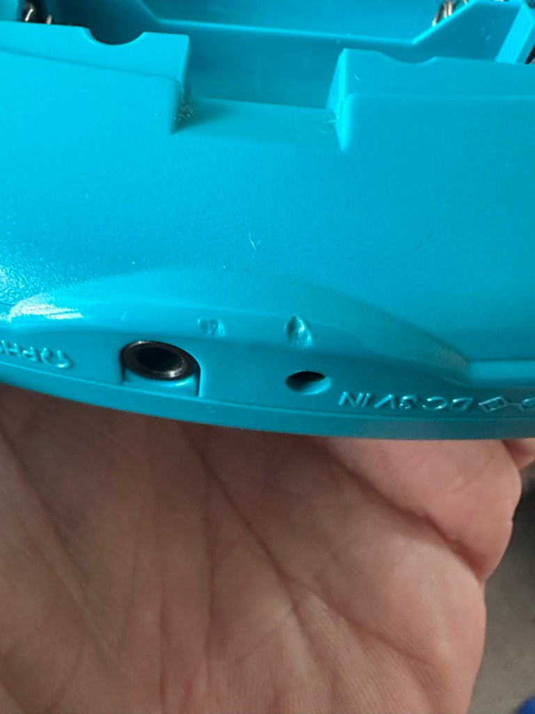
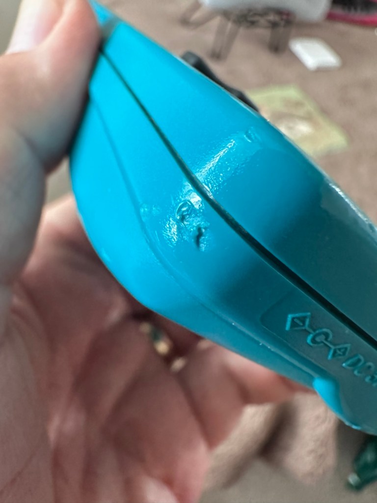
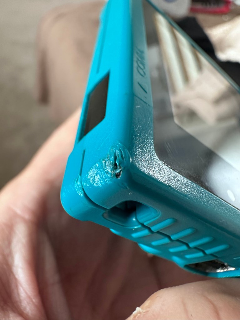
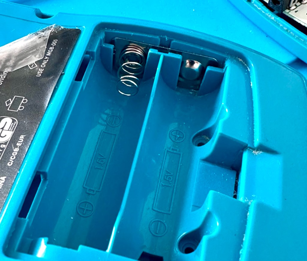
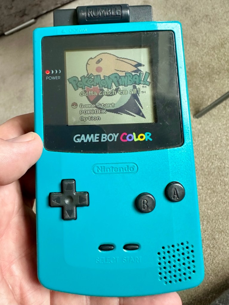
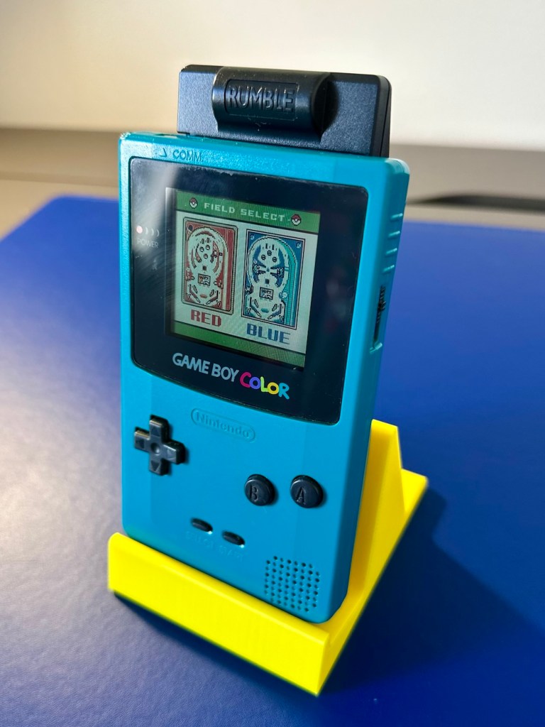
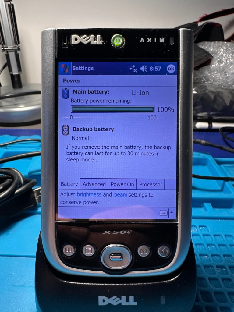
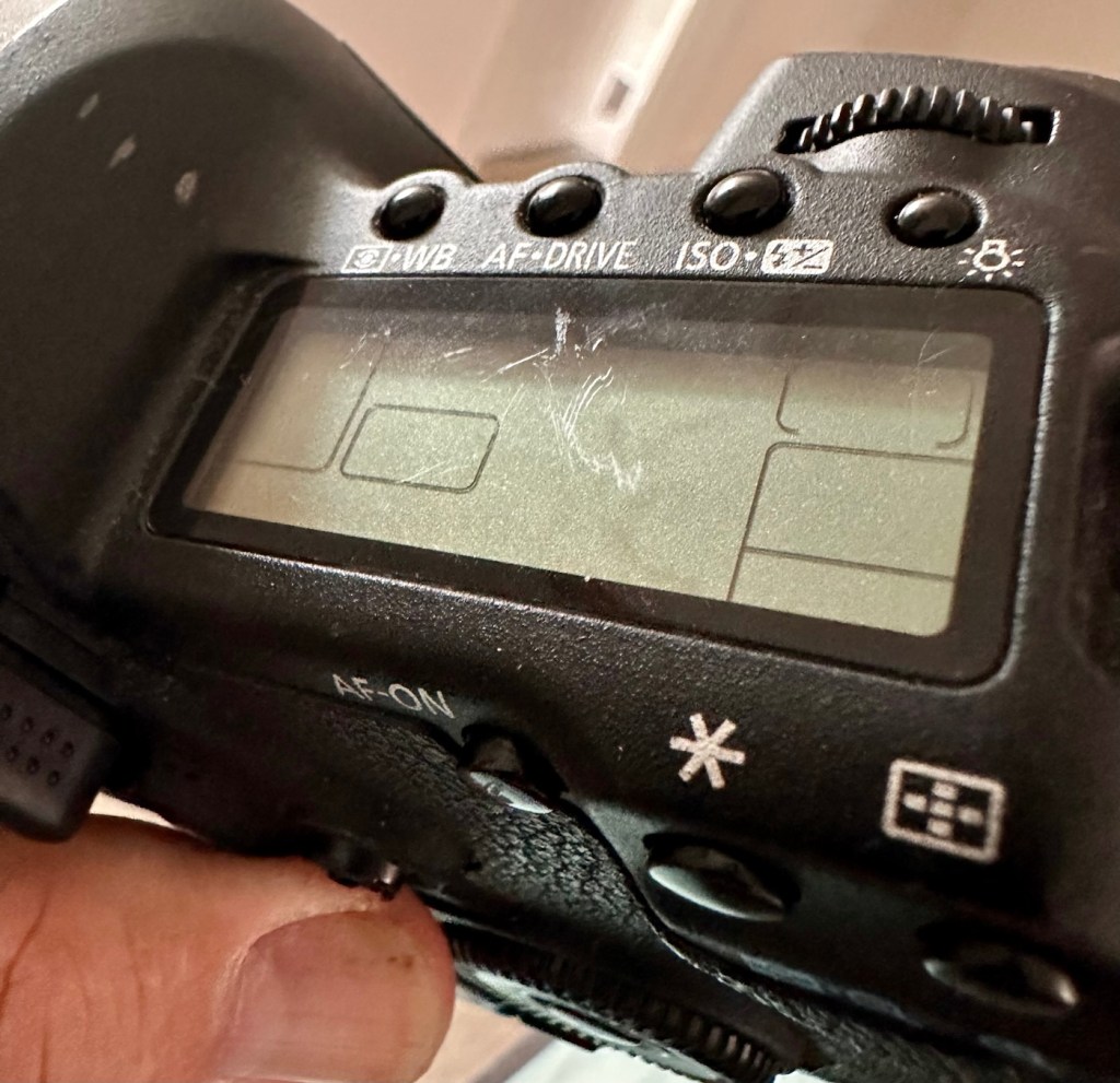
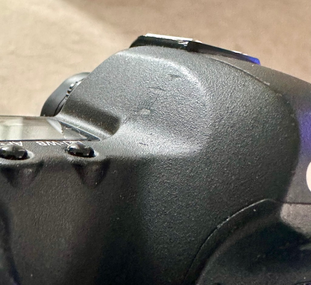
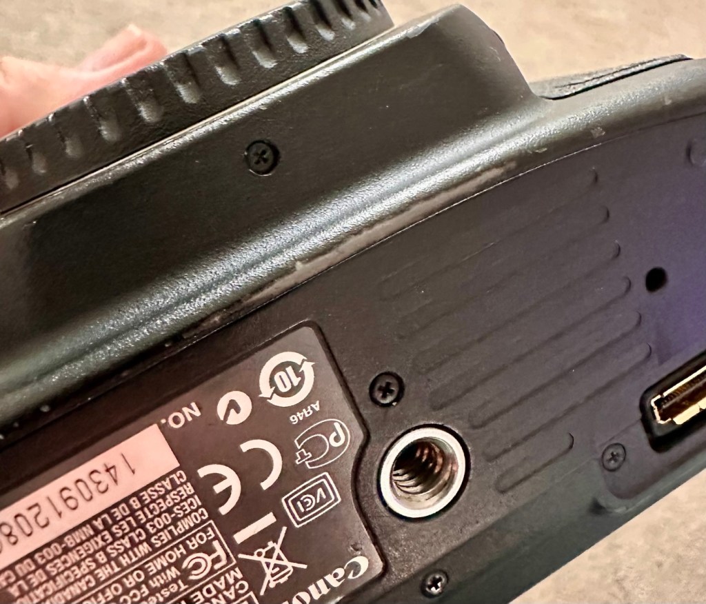
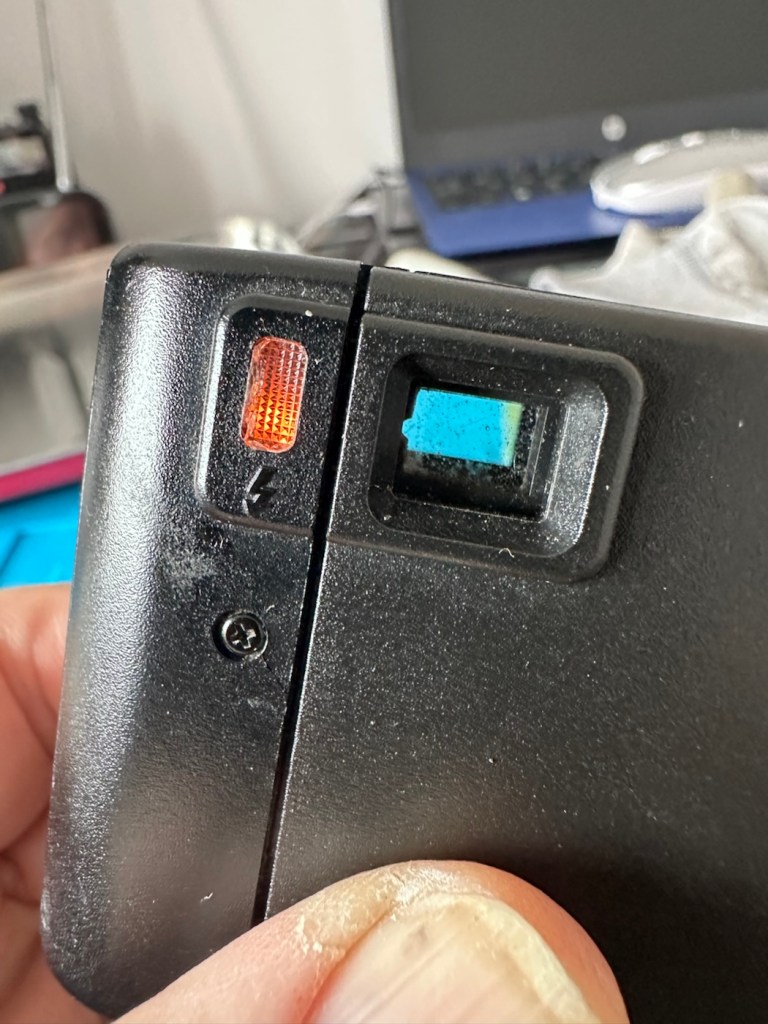
Battery contacts show no sign of corrosion but are a little grubby. There are signs of good use but nothing really bad to be honest, all connectors and buttons appear to be doing what they should. The unit is in good need of a thorough clean, as it does look a little worn in that aspect. Screen has very minor scratches, nothing that will cause any issues. The little acrylic lens by the power light is missing and there is as stated, no sound even though we do have a picture and are able to play the games. In all aspects the unit is functioning, just with no audio.

This is a fair unit, it will clean up and if we can get the audio working we have a potentially very good unit.

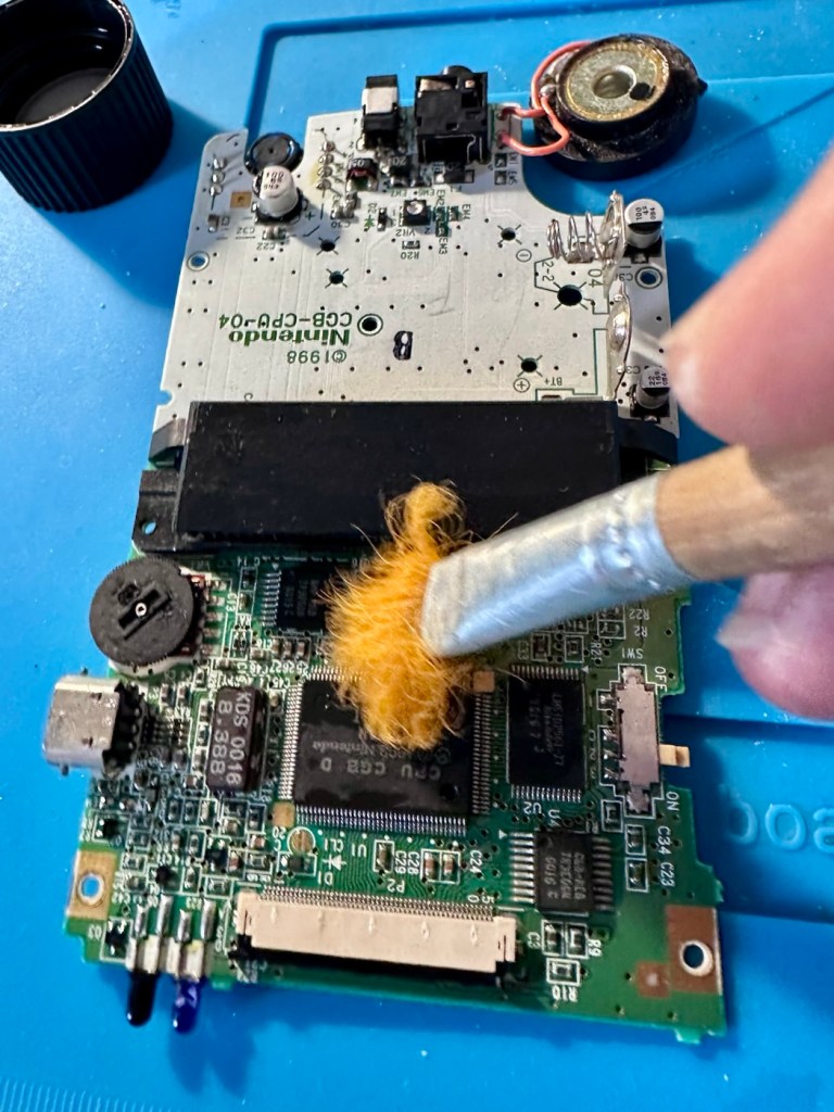
It is dirty though, and a good clean will make an immense difference.

Repair:

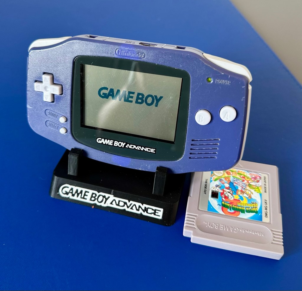
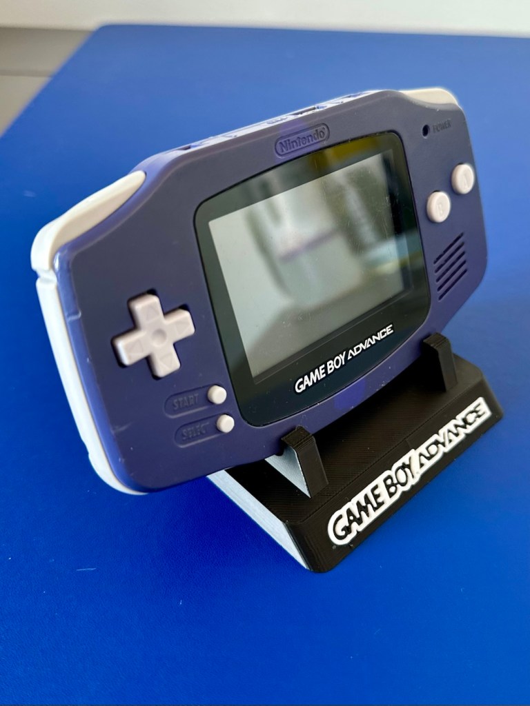
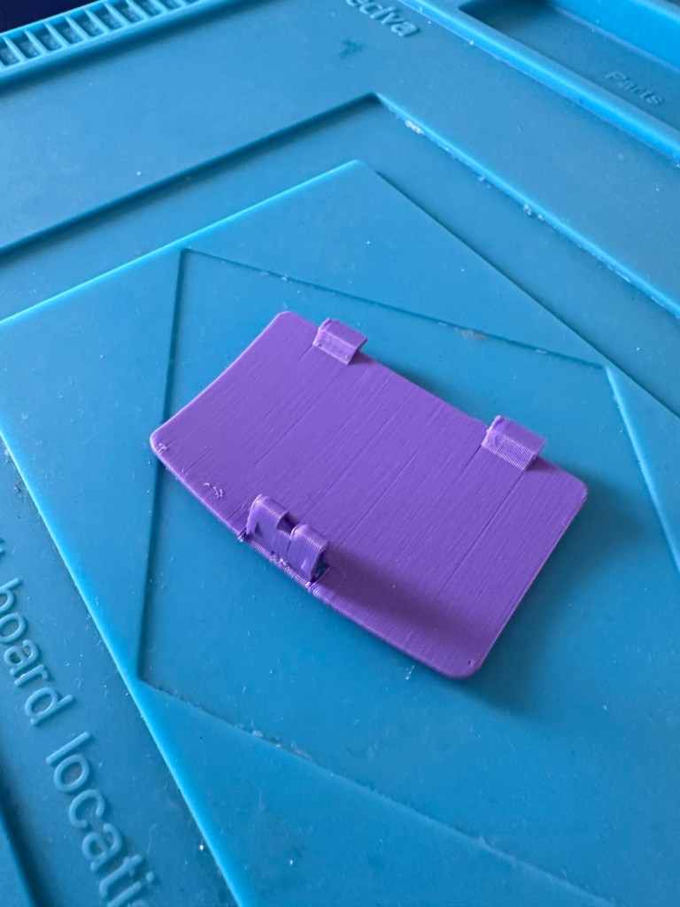
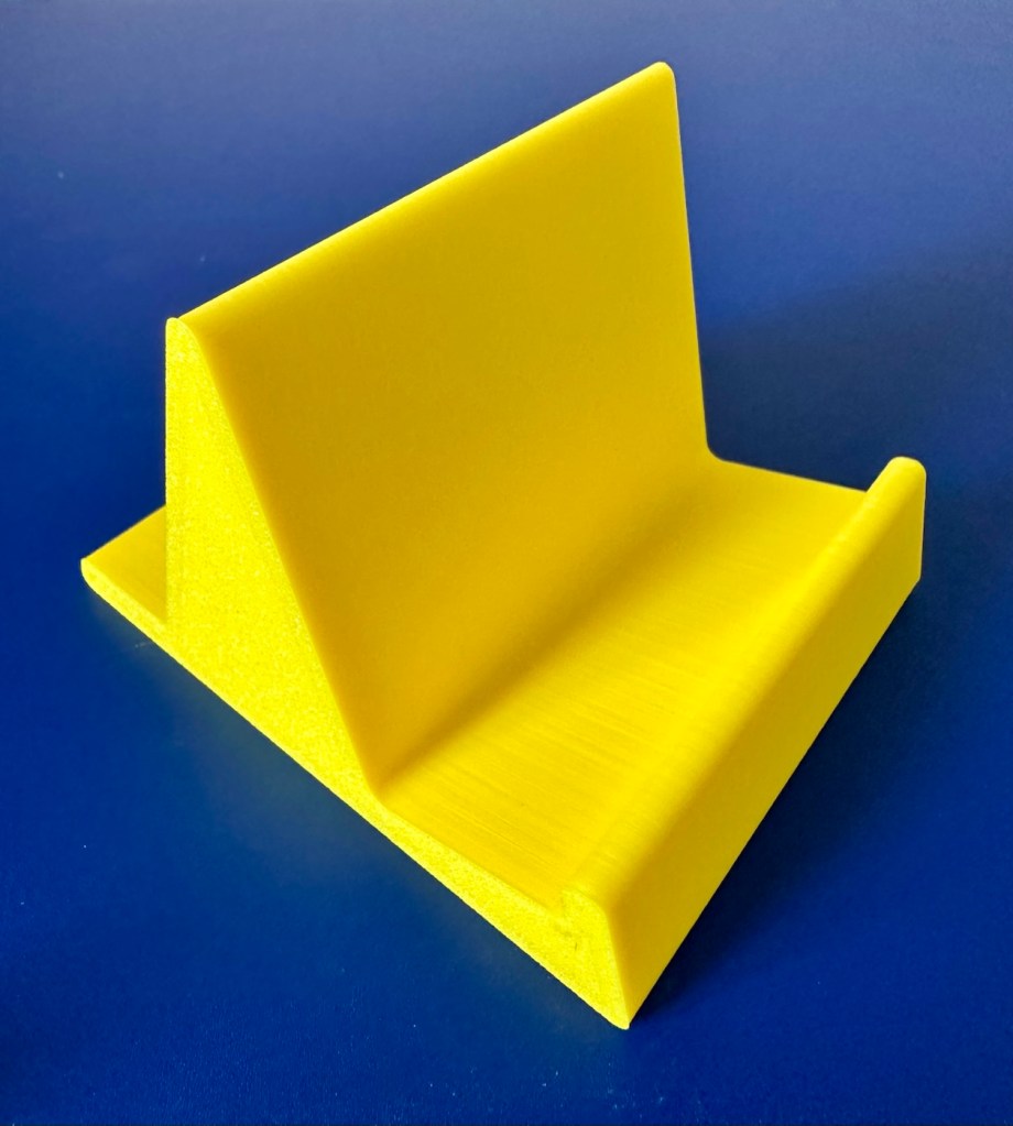
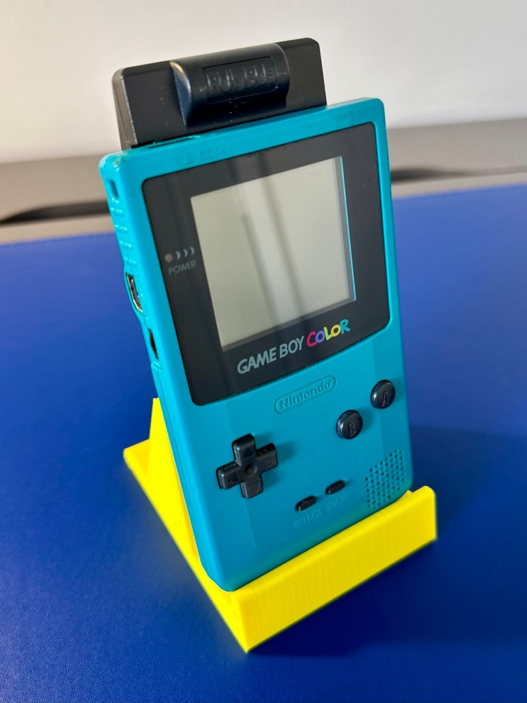
The printer is on and warmed up so before we get repairing, let’s print a suitable display stand for this unit.

Display stand printing

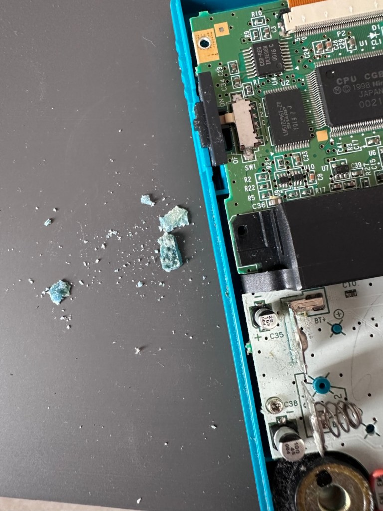
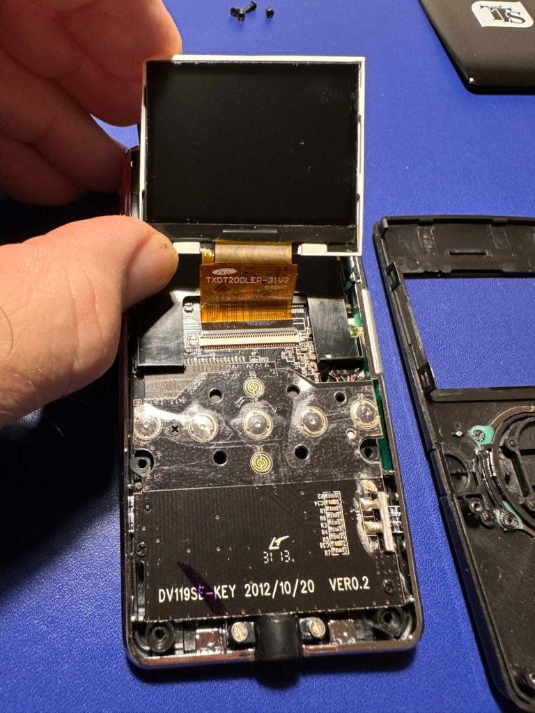
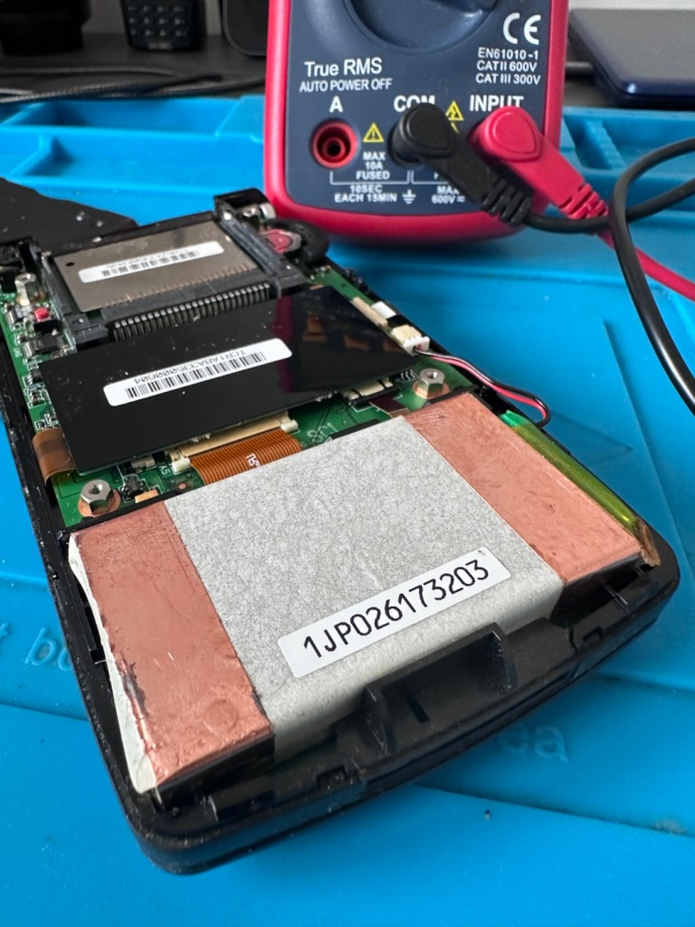
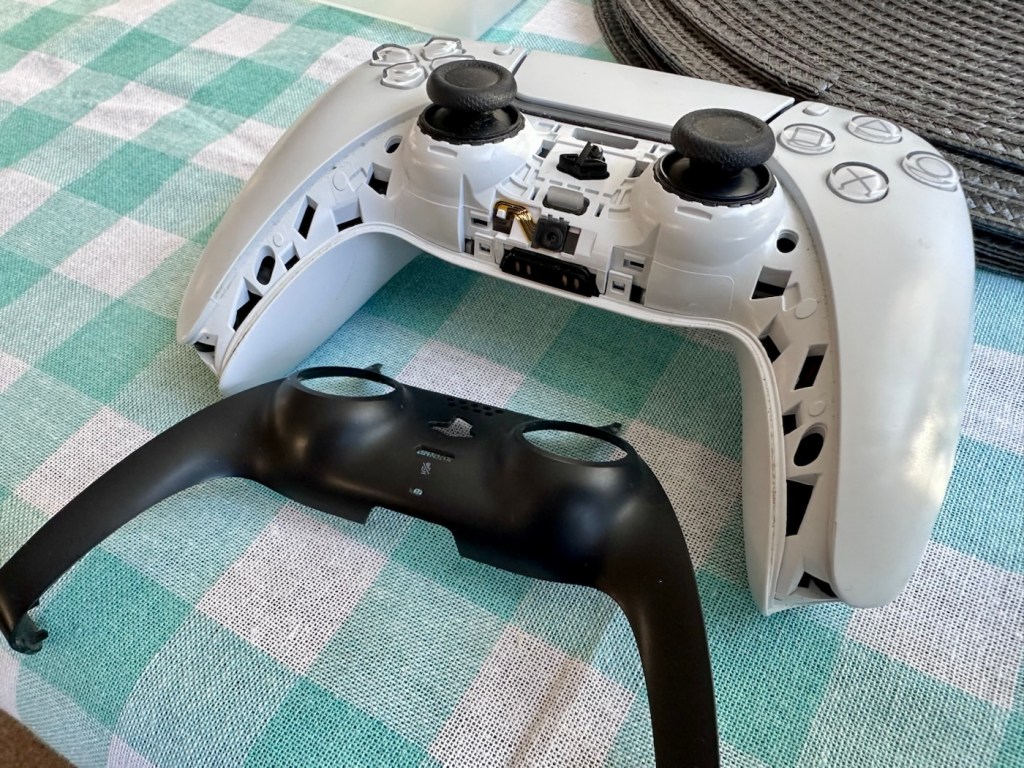
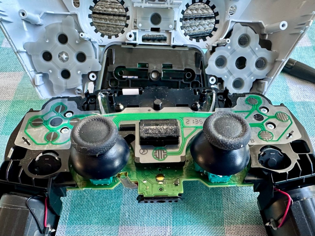
Now let’s open up the unit and see what we have inside.

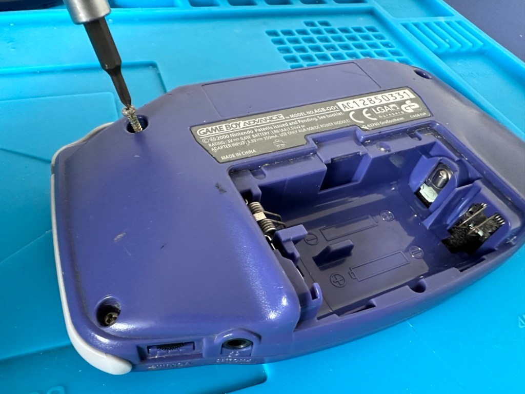
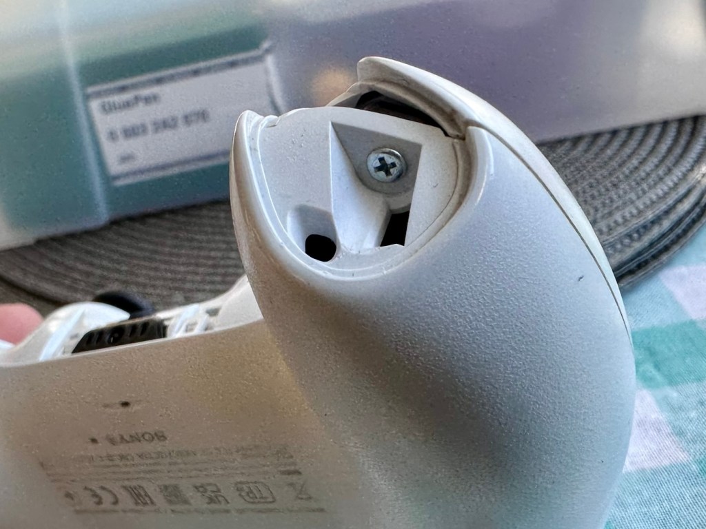
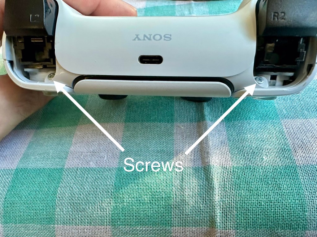
First there are seven tri wing screws securing the shell. Remove these and the rear of the unit just lifts off.

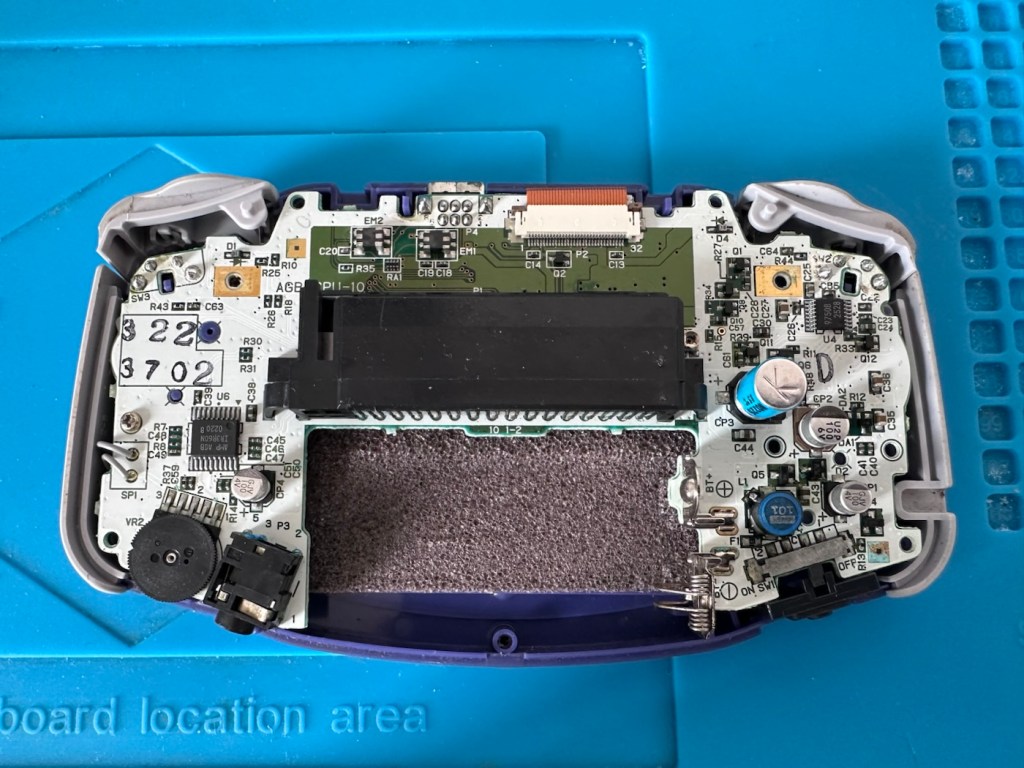
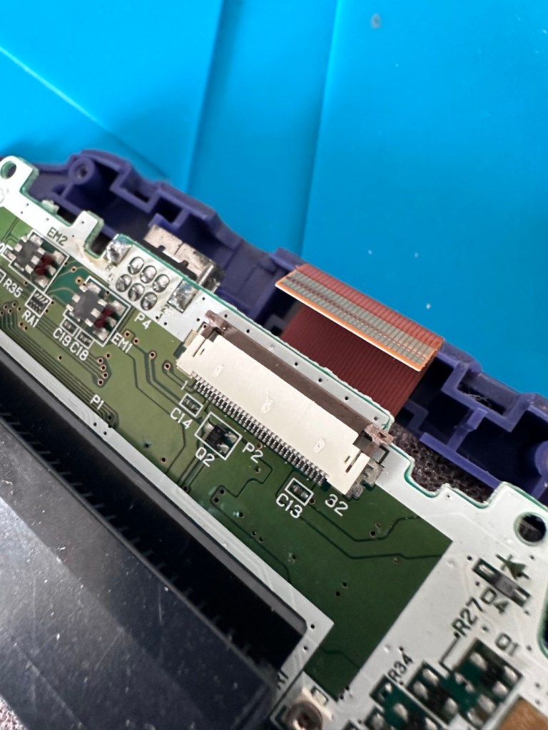
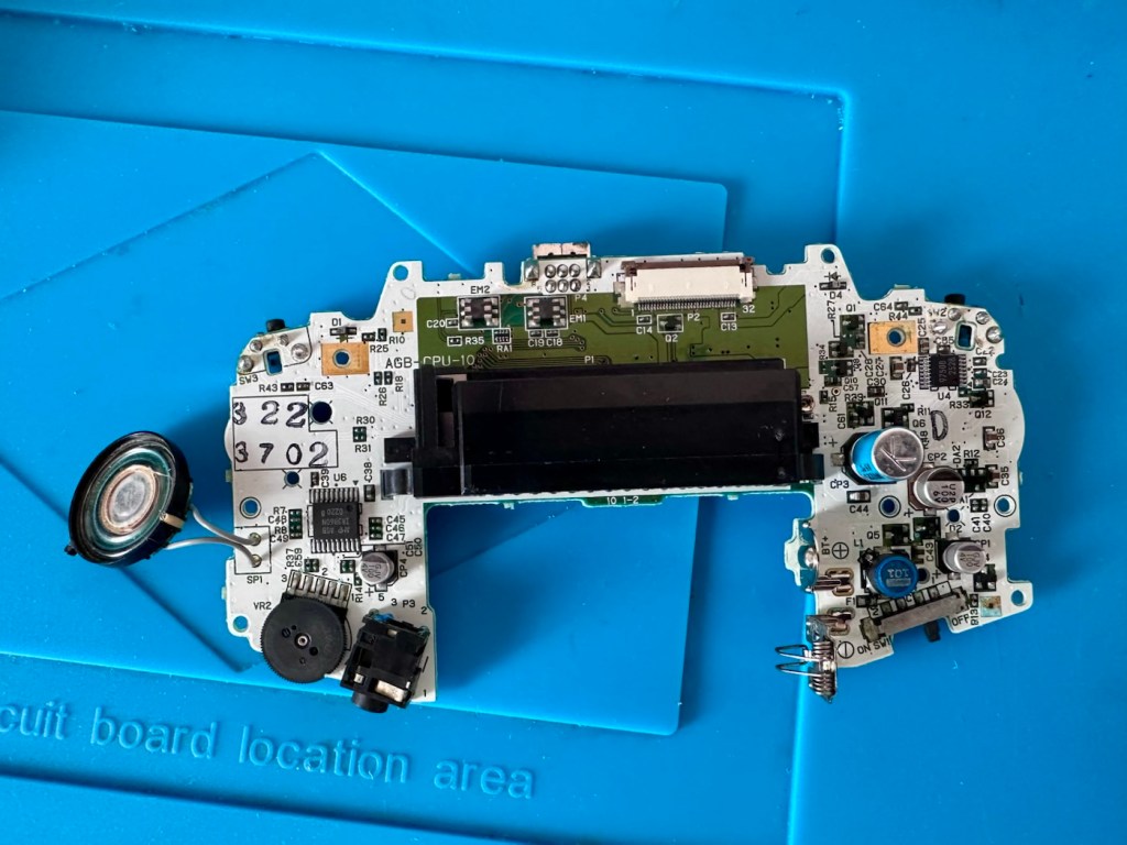
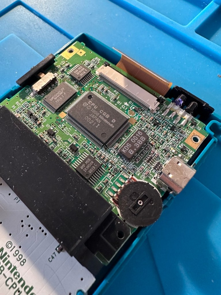
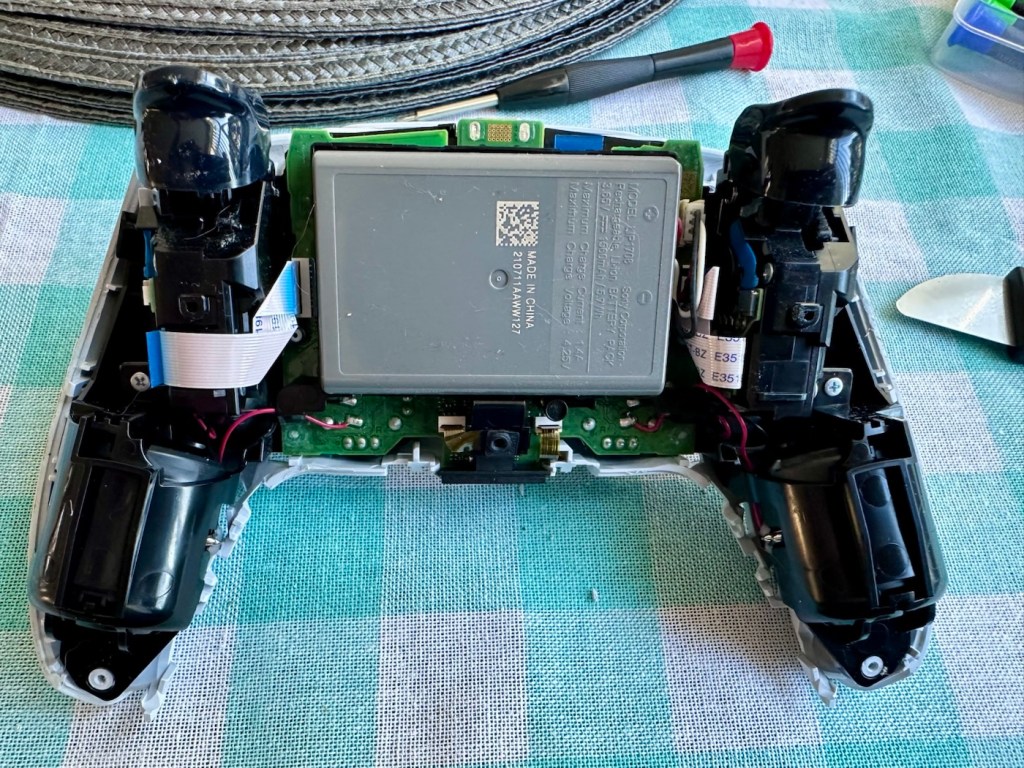
Next there should be three screws to remove the mainboard but there is only one. Someone has previously been in this unit and has left two screws out. Next we remove the ribbon cable that secures the screen to the mainboard.

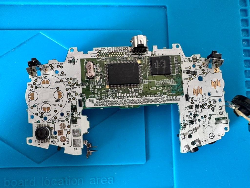
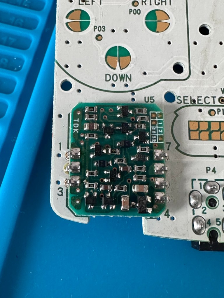
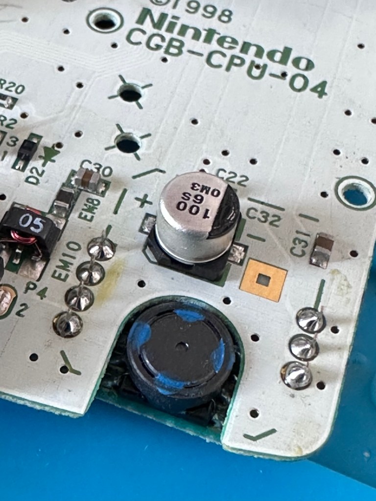
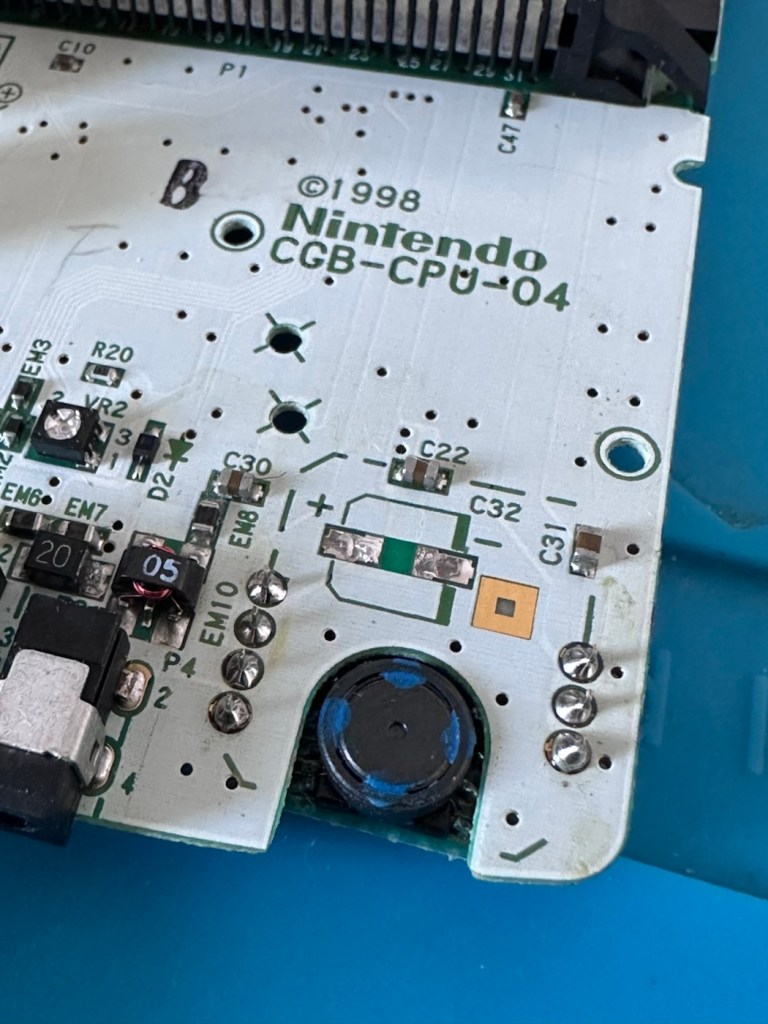
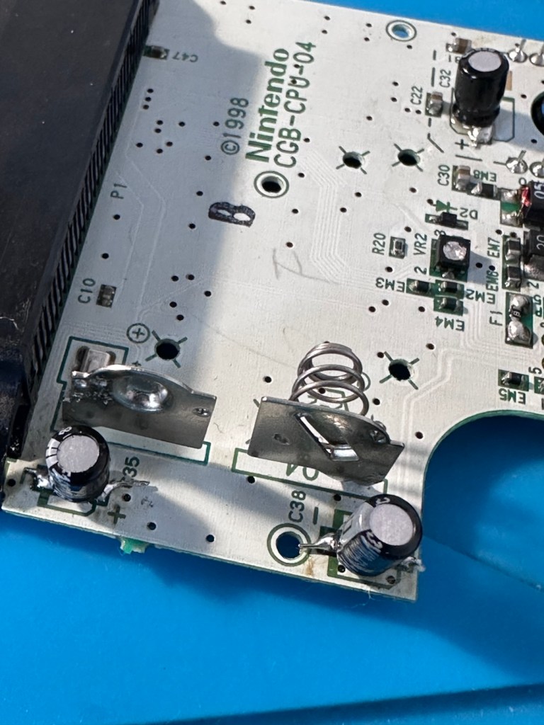
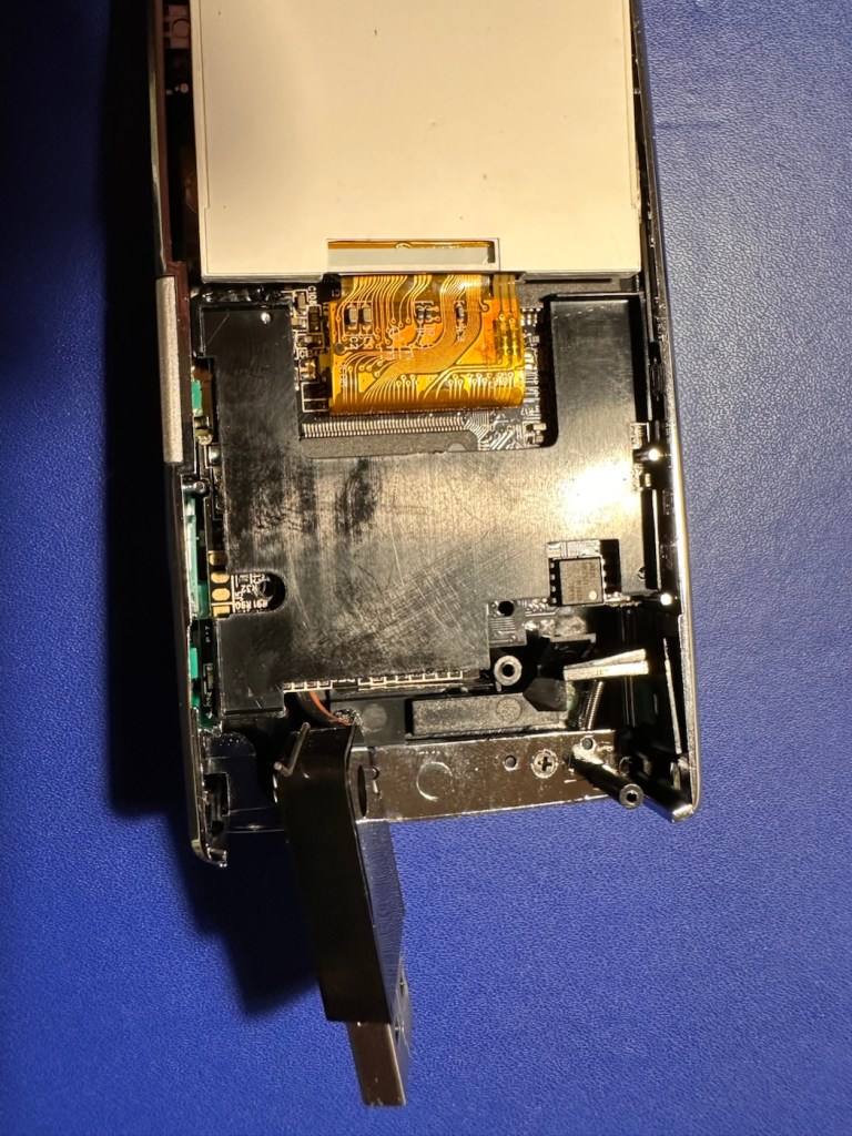
We now have free access to both sides of the board and can put everything else to one side to start our fault finding process.

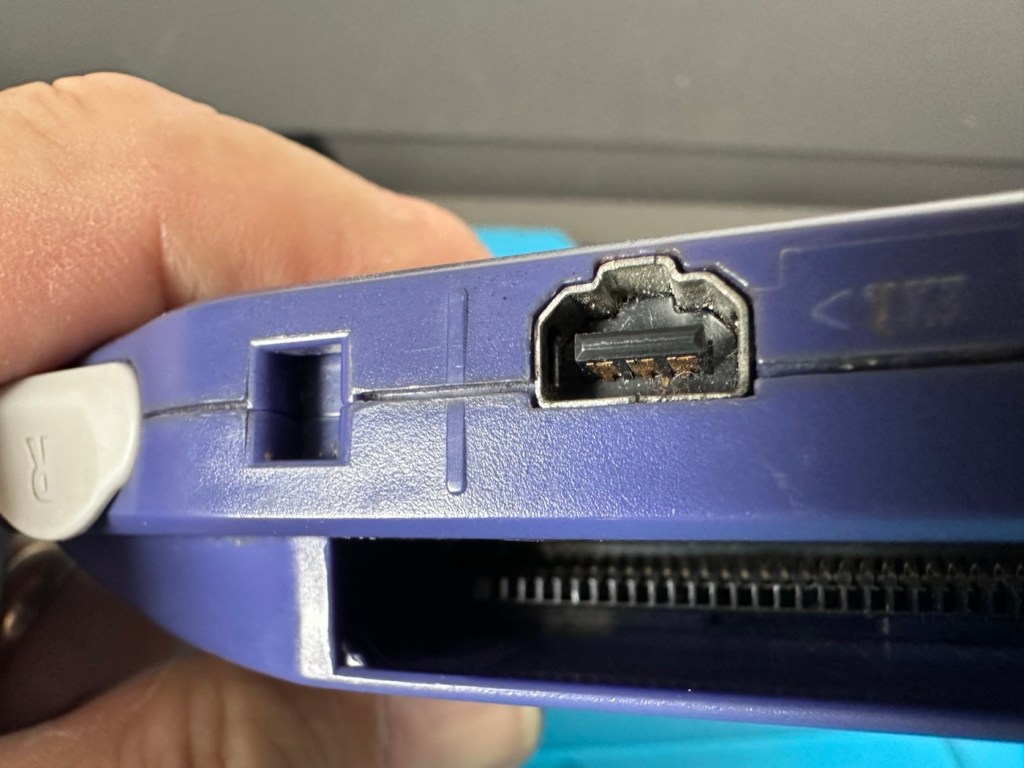
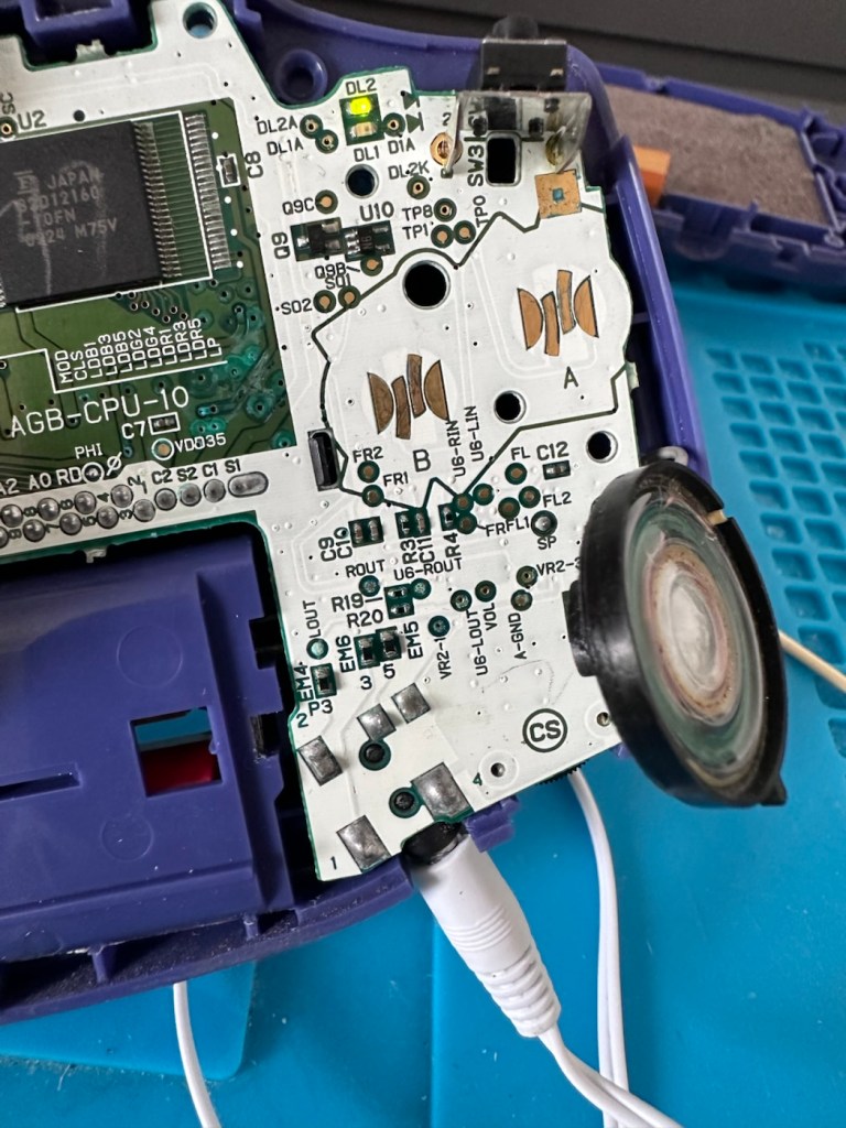
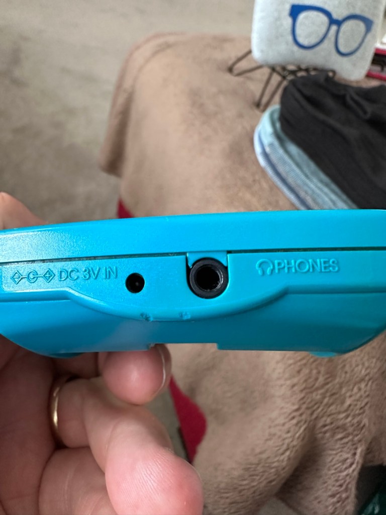
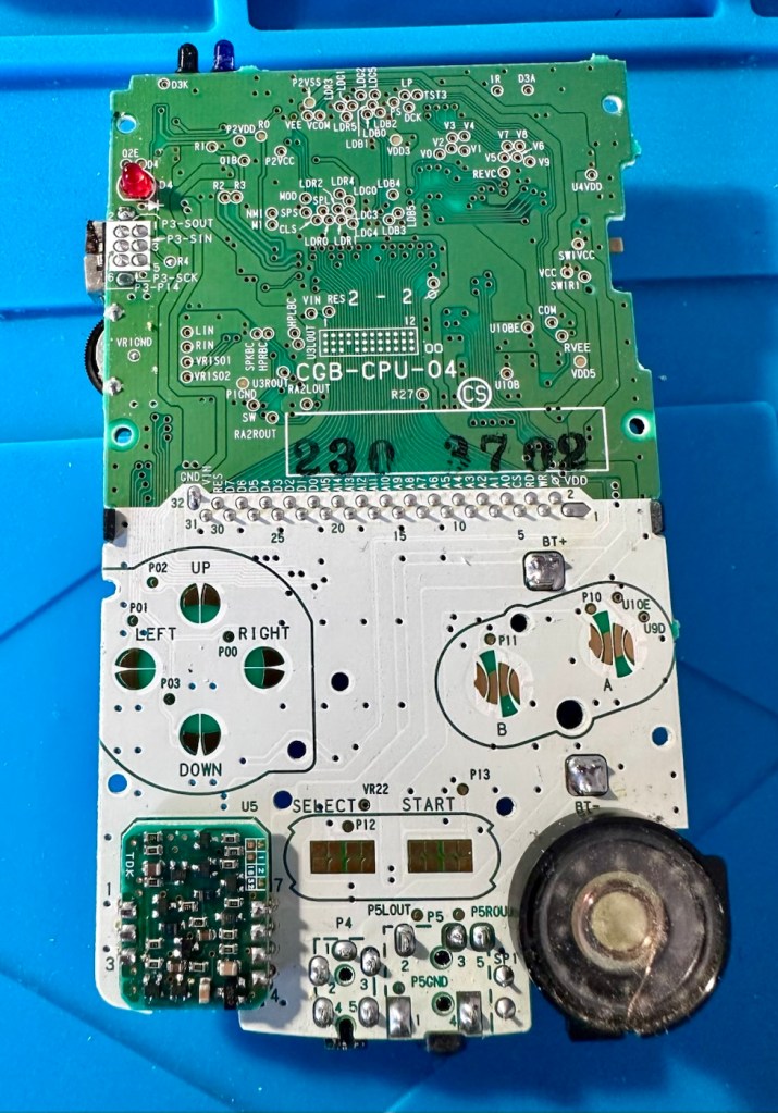
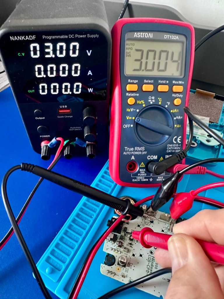
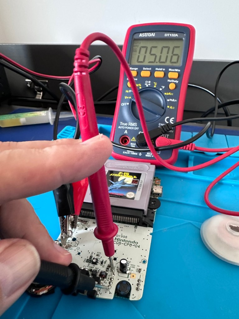
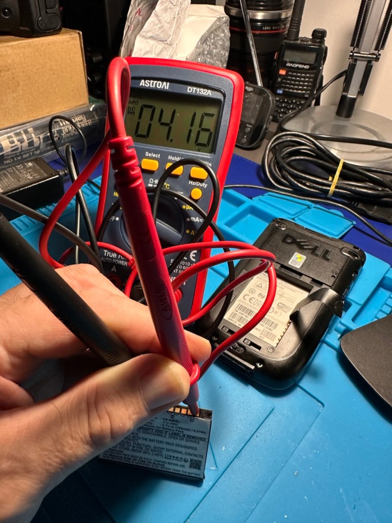
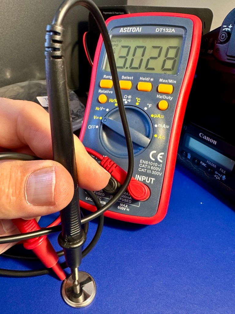
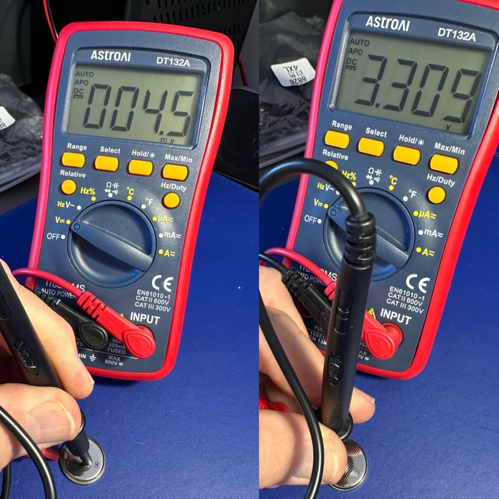
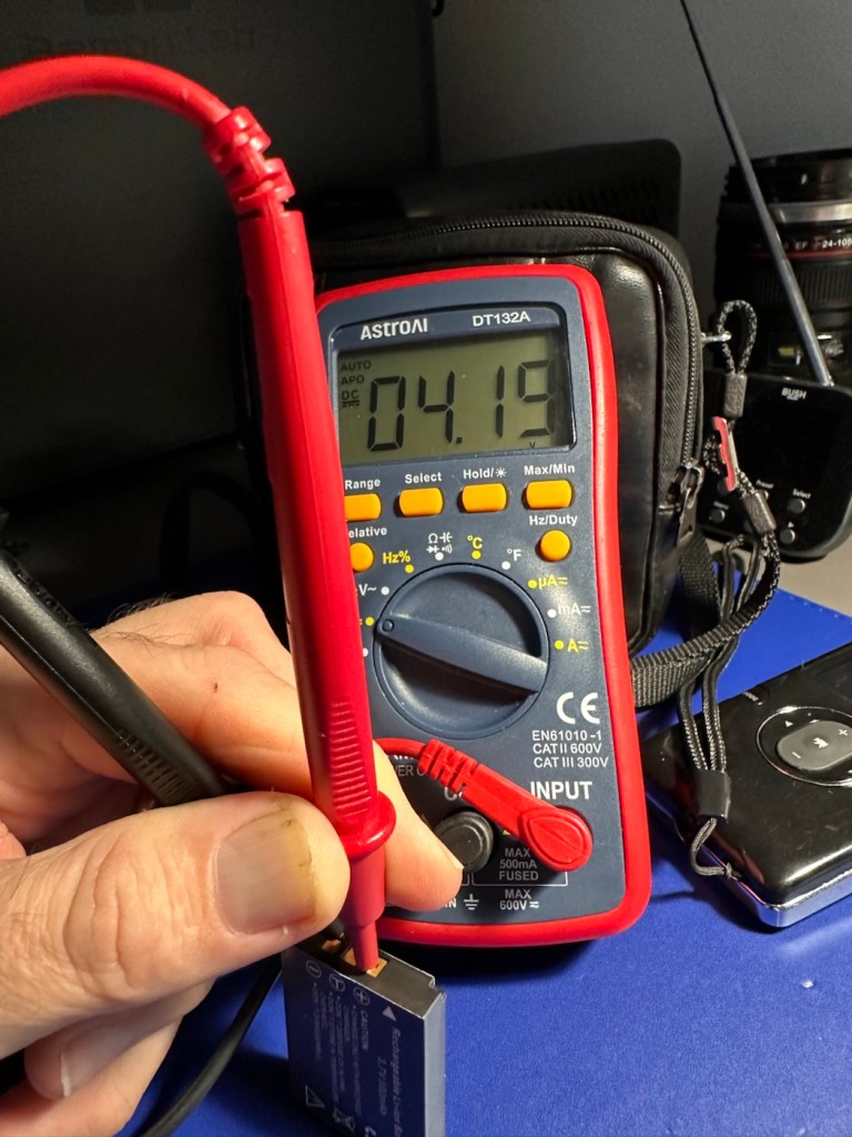
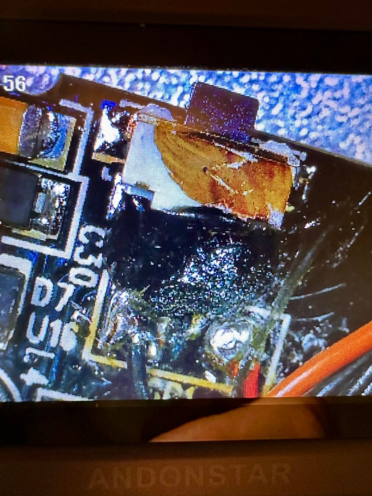
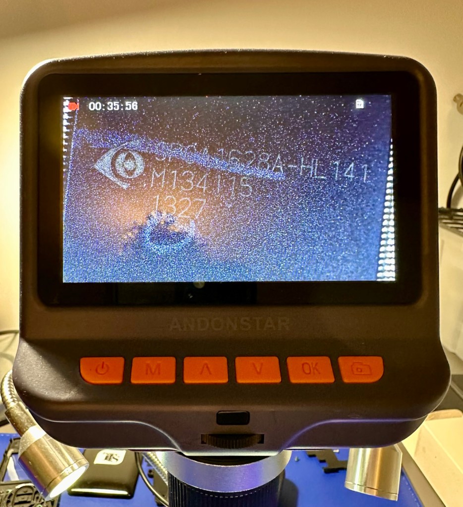
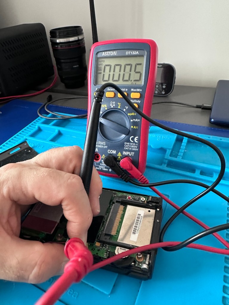
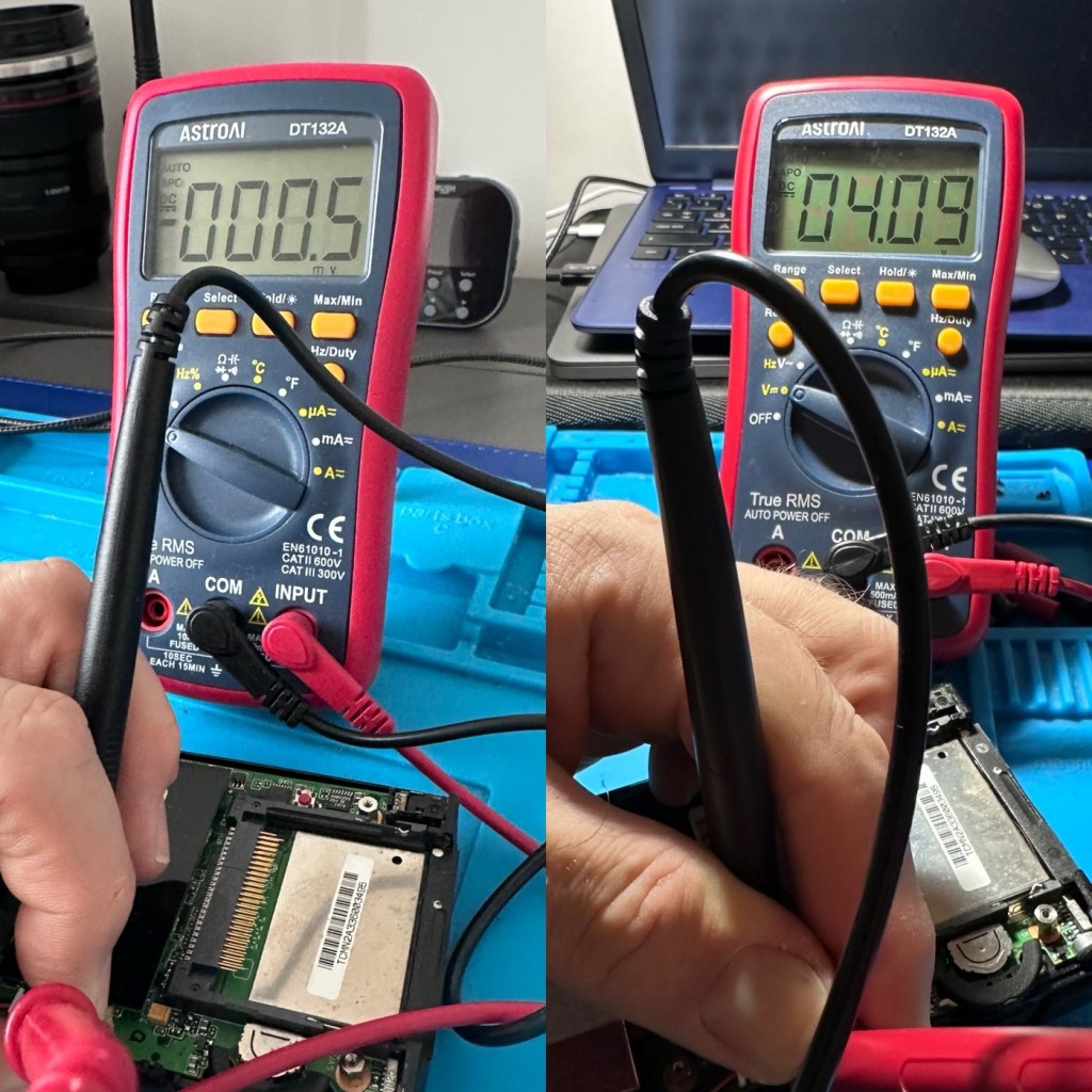
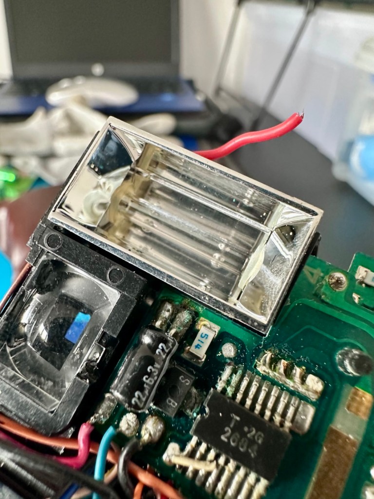
First things first, let’s check the speaker. With the multimeter it’s showing 8 Ohms so I’m happy that the speaker is ok. A quick check for shorts and not one capacitor shows a short, I plug in a set of headphones and I can hear sound, but as soon as they are unplugged there is no sound again. My attention is now at the earphone socket.

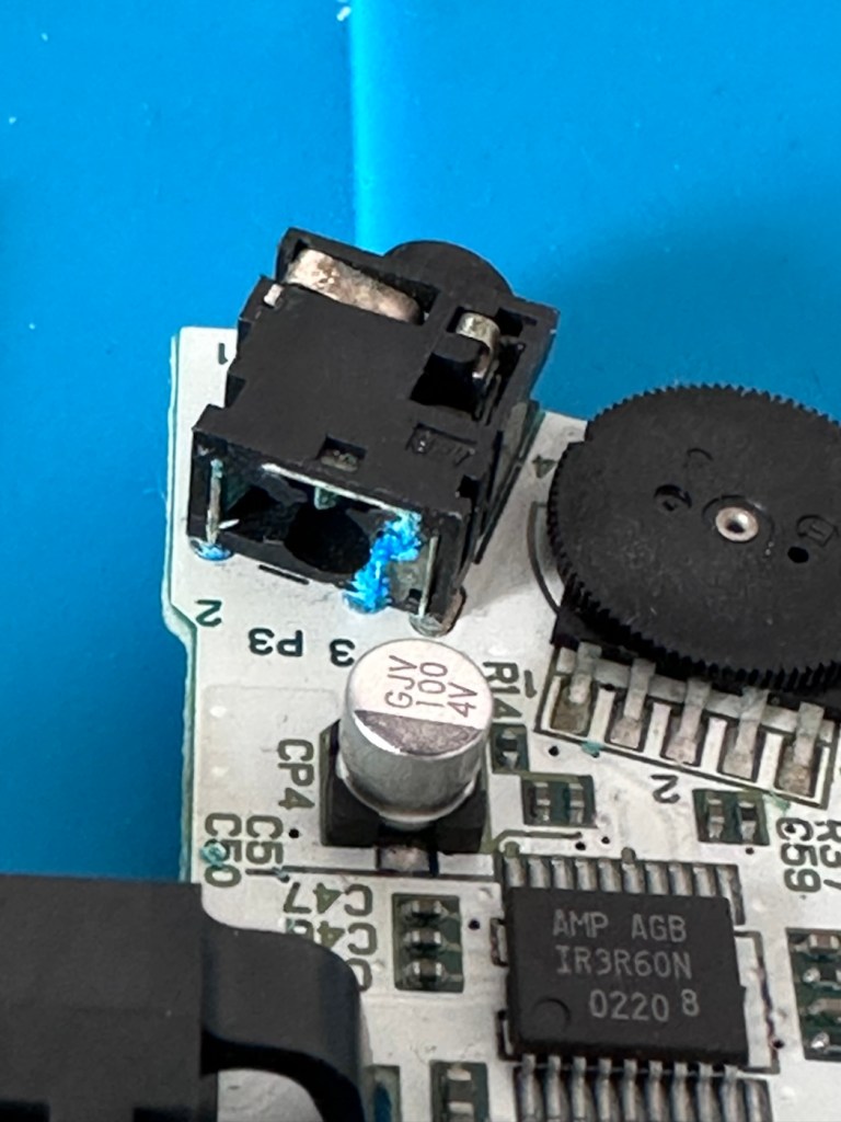
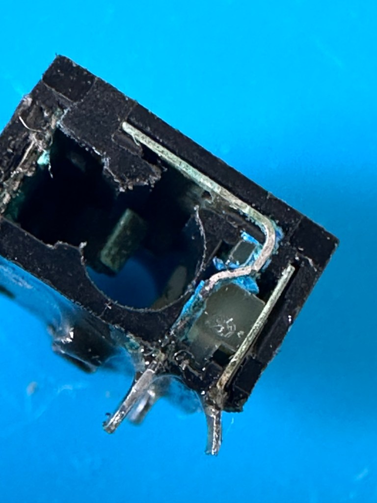
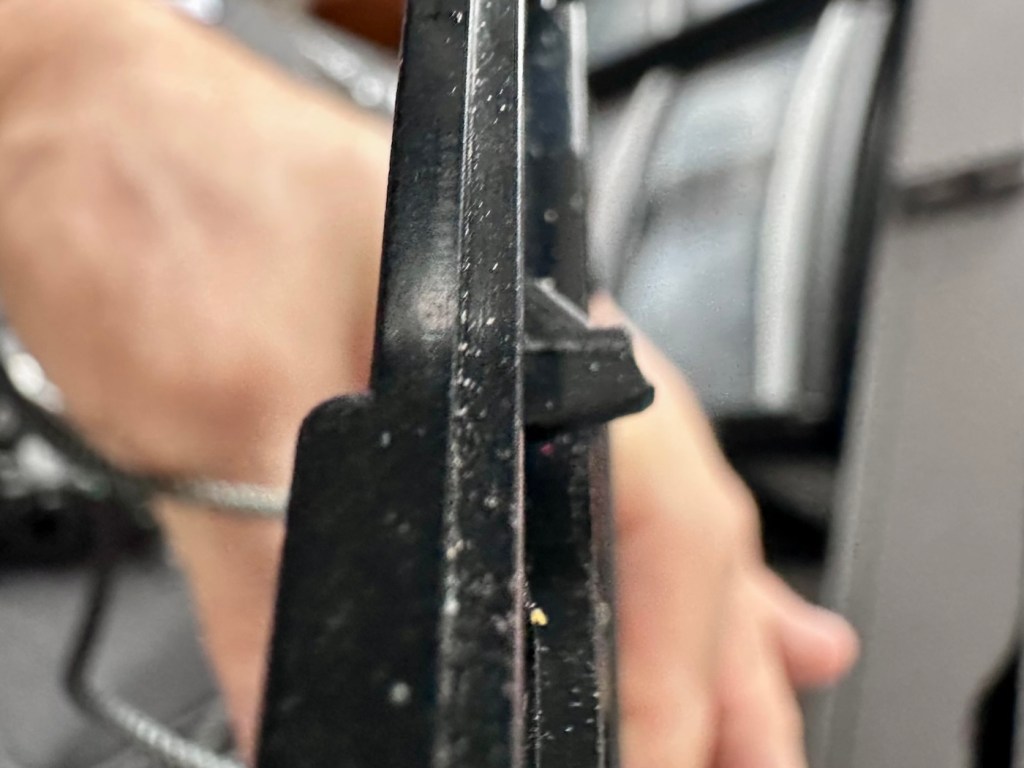
On close examination other is a considerable amount of battery acid contamination in the earphone module. This is strange as there is none evident in the battery contact area. A close look around shows some spots of contamination, however these are easily cleaned with some IPA. I have a feeling this may have been a previous issue and the person in here prior to me, has cleaned up, but given up on the repair.

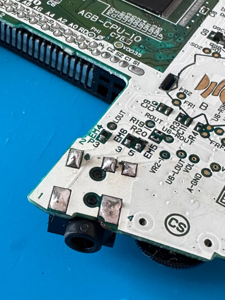
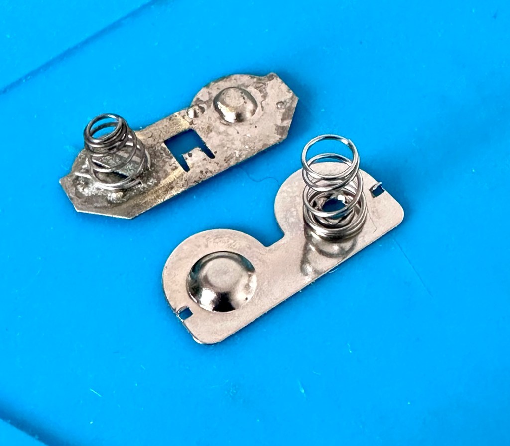
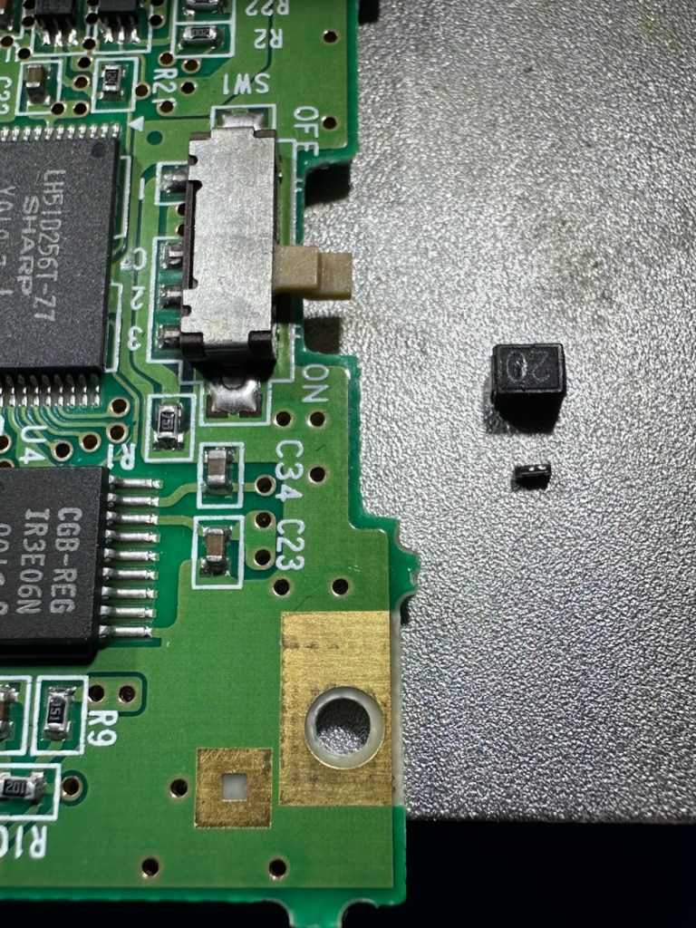
I remove the earphone module, and clean the surrounding area.

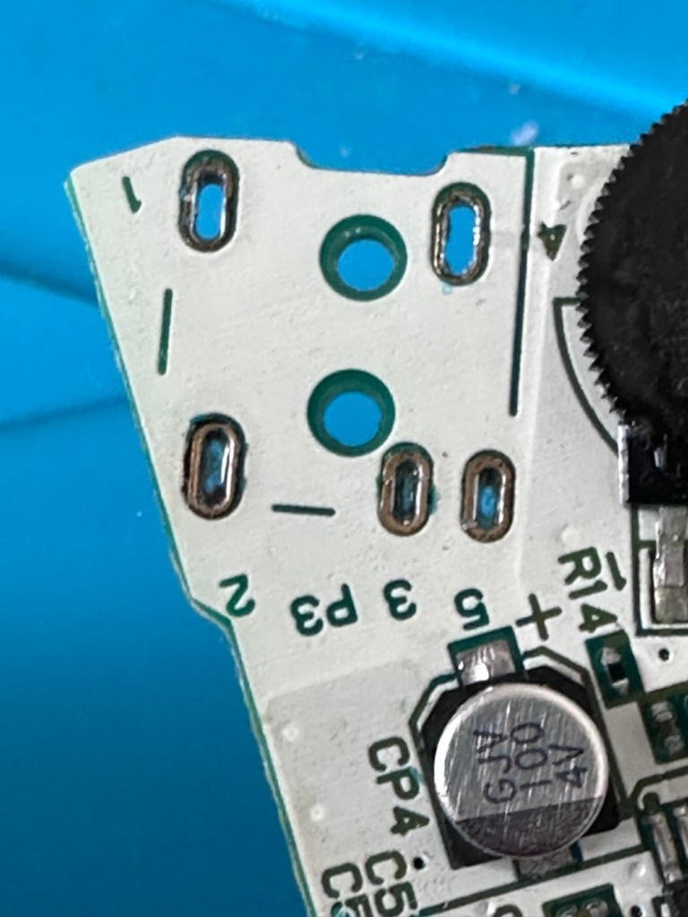
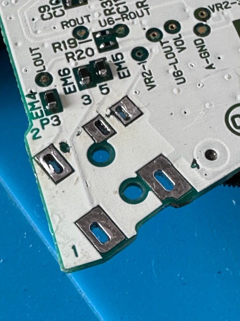
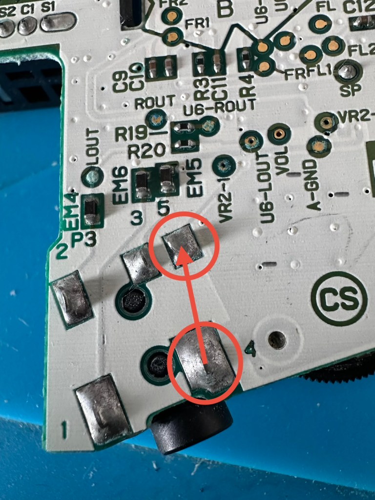
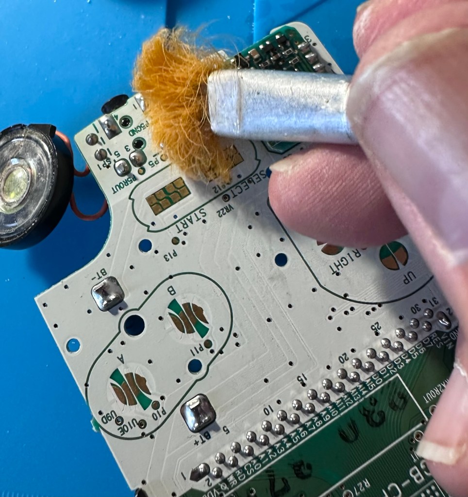
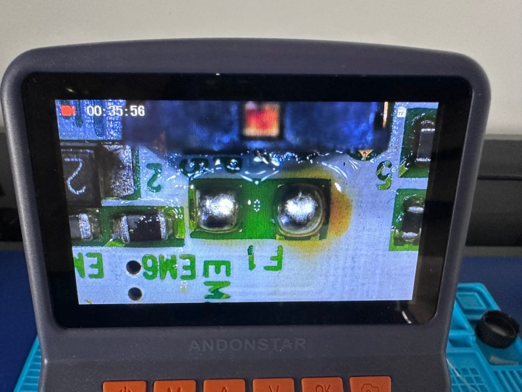
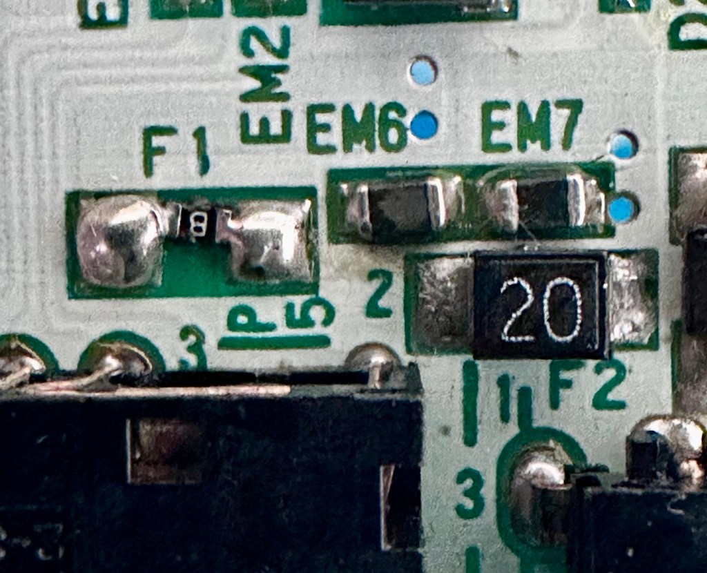
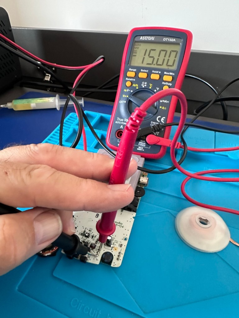
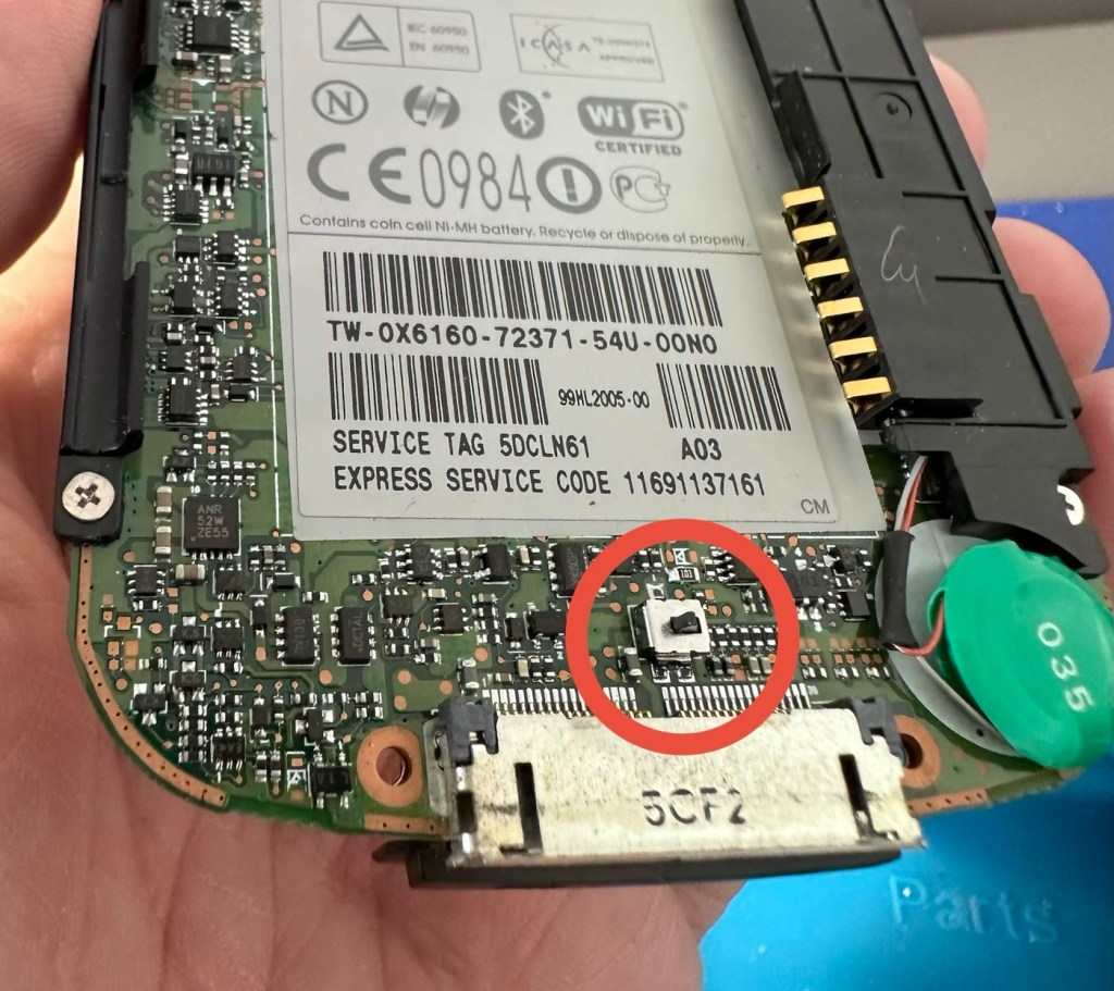
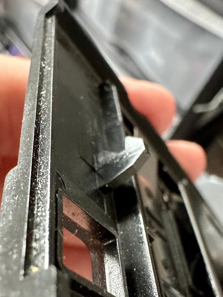
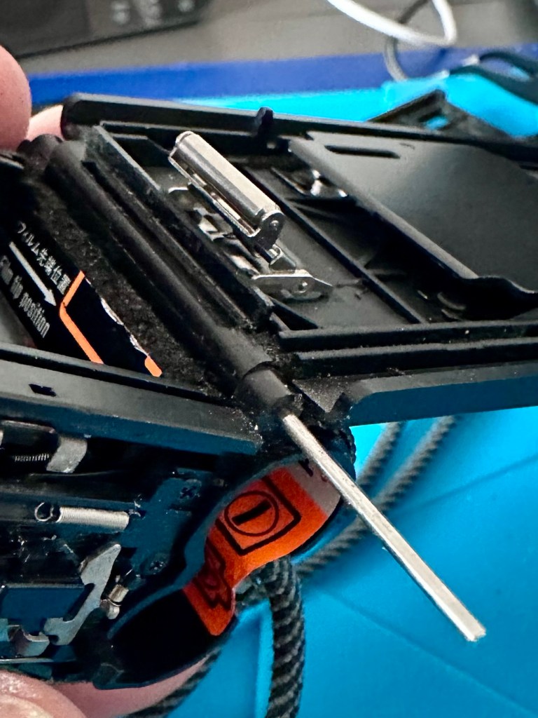
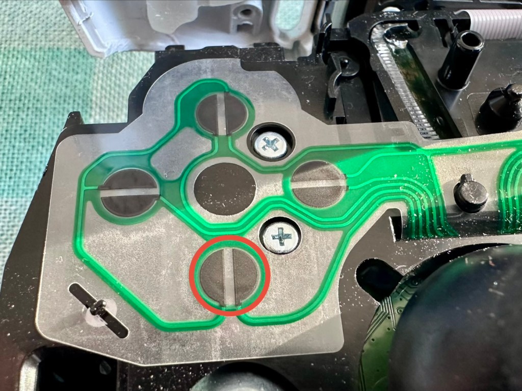
A simple check here is to see if there is any continuity between the two tabs that occupied positions 4 & 5 as marked on the mainboard. This check is carried out on the actual module. If you have continuity between these two pins, then in theory the circuit is good, and the speaker should be working. My results here were negative as there was no continuity on this module between those points.

The way the earphone works is thus. Plug the earphone jack in, it opens up the contacts and by passes the external speaker. Remove the earphone jack and the contacts close, opening up the main speaker. If there are contaminants on the contacts, this can prevent continuity and hence there is no sound on the main speaker.

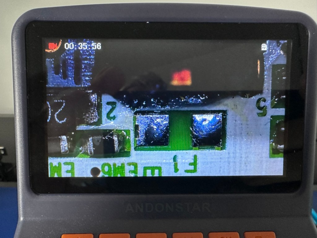
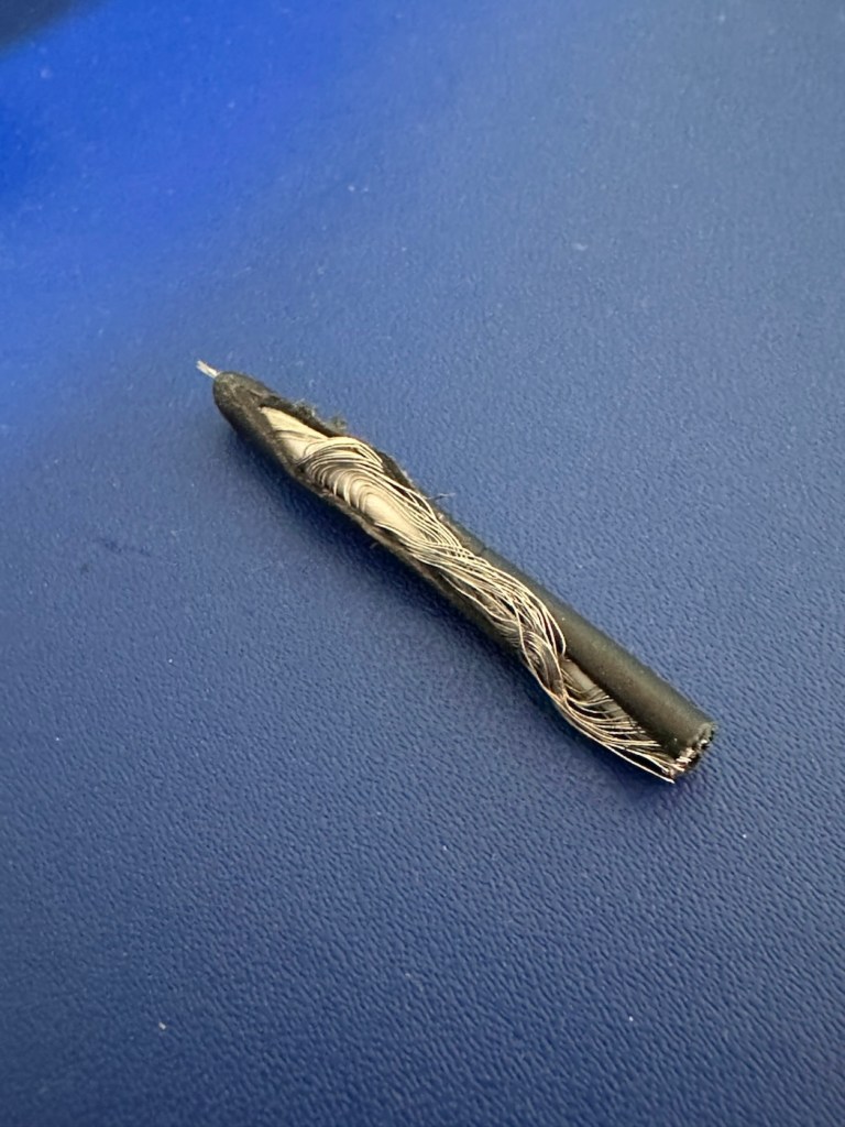
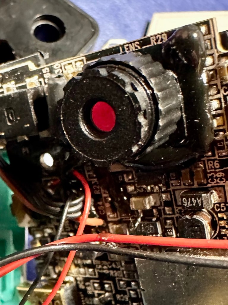
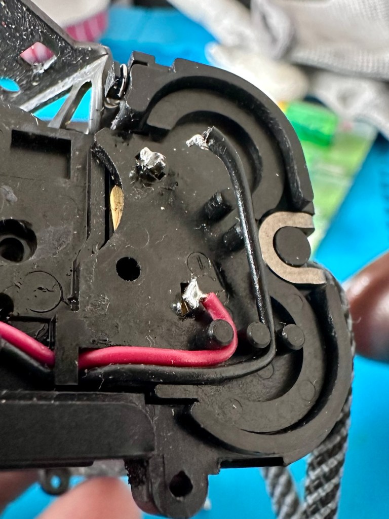
You can double check that this is the issue by soldering a small wire between points 4 & 5 on the mainboard in theory by passing the earphone circuit leaving the speaker circuit open and accessible.

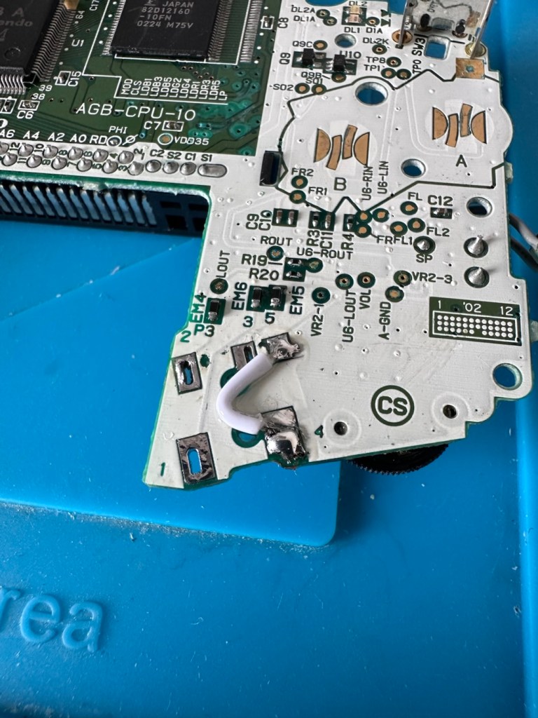
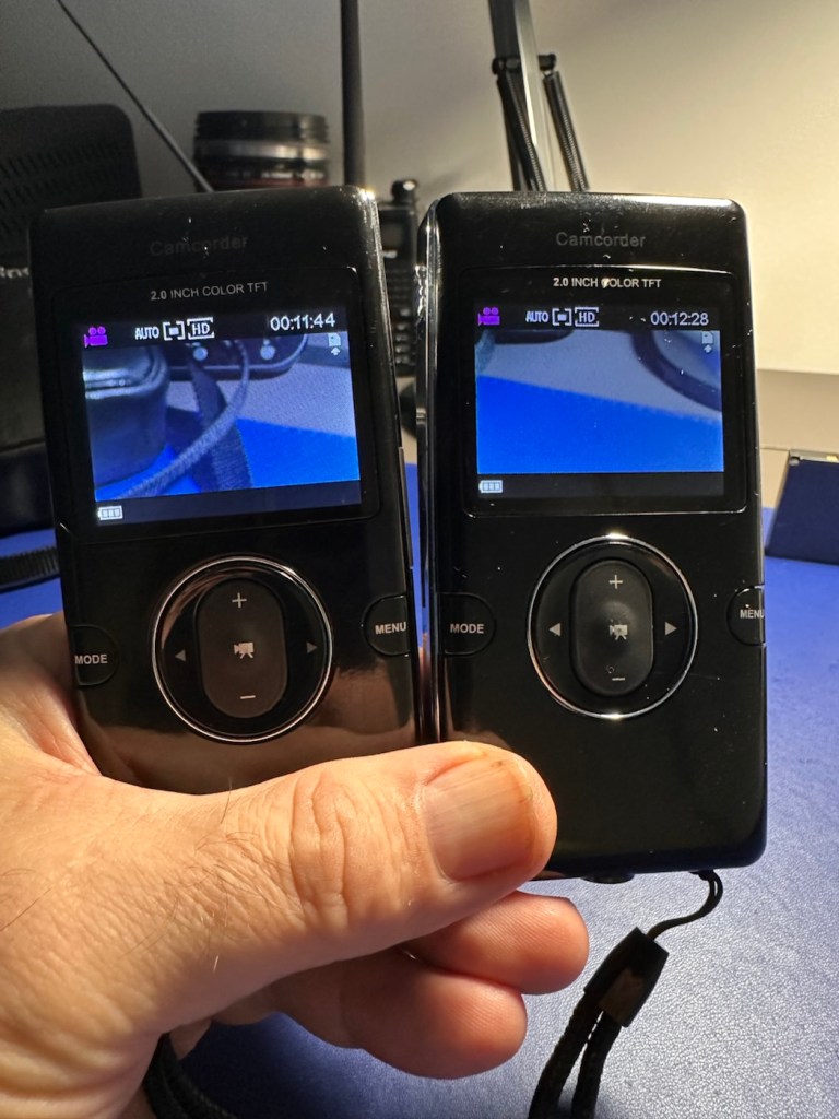
And my suspicions were correct, this small video below was the result of bypassing this part of the circuit.

We have sound in the speaker

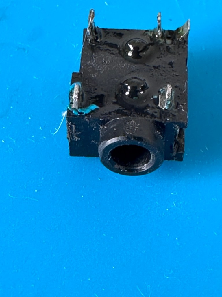
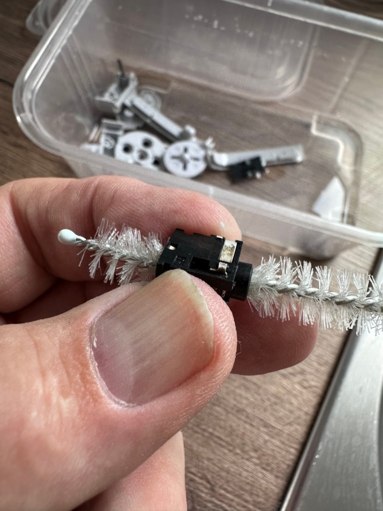
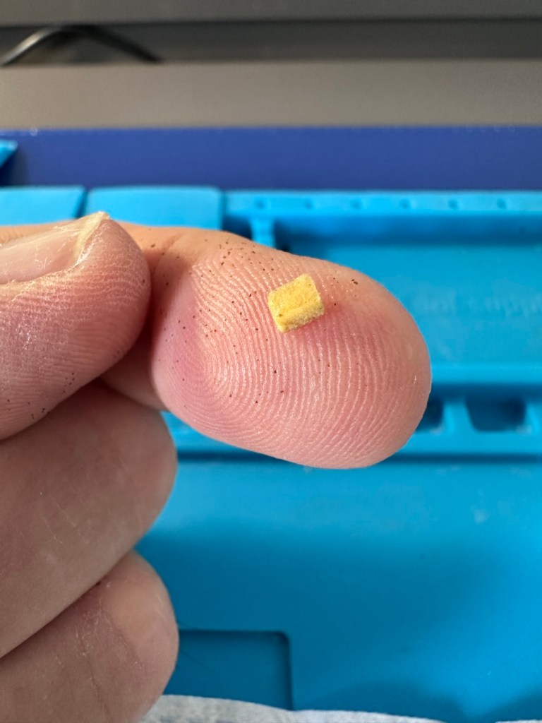
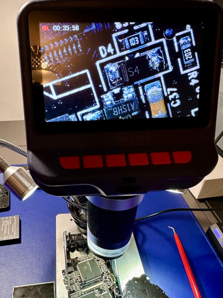
Looking inside the earphone socket it was easy to see this piece had a solid lump of contamination exactly where I was expecting to see it. I have no spares of these and to obtain one off of the auction sites is an absolute ripoff. I can order one from our friends in China but I’m looking at a four week turnaround here, and I’m inpatient and not willing to wait that long. I’m going to try and repair it.

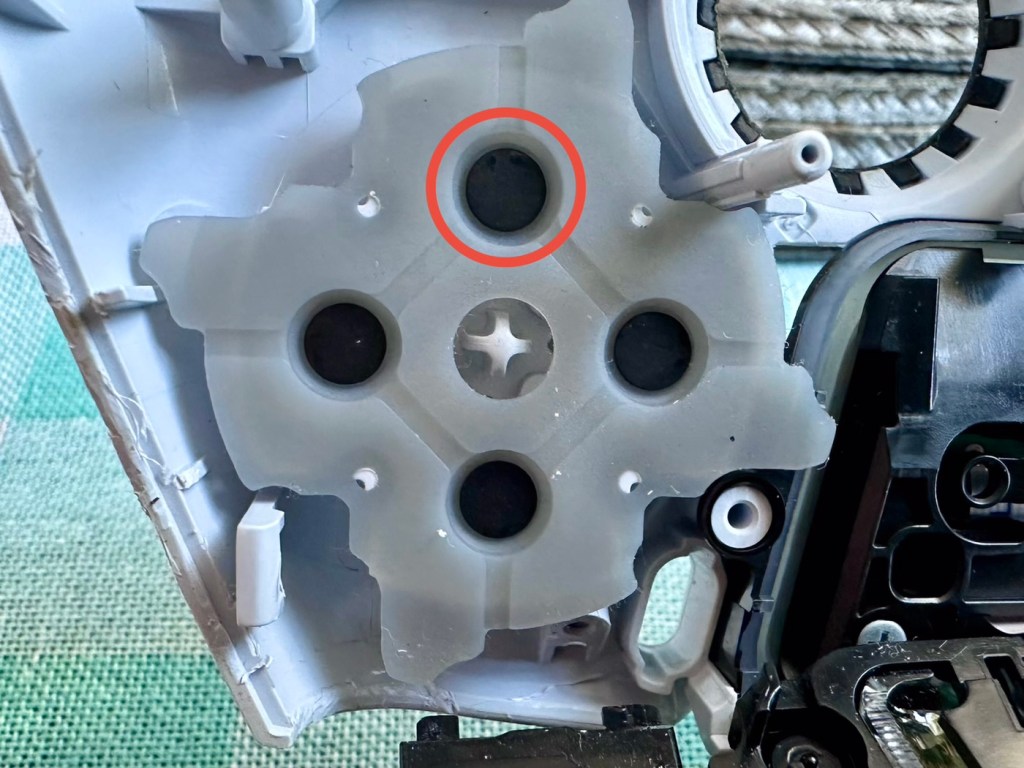
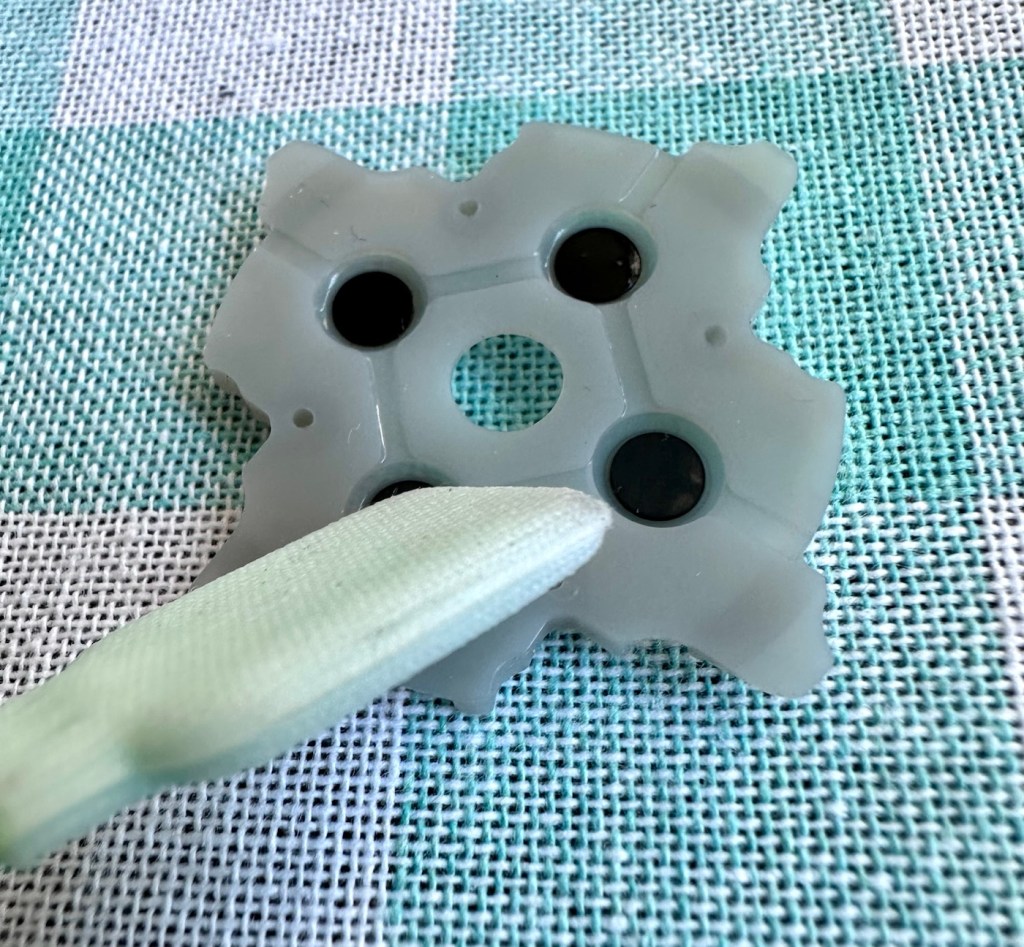
I’ve gathered everything up that needs cleaning, buttons, connectors, screws, pads and the suspect connector, and dropped the lot into a small dish of white vinegar. White vinegar is great for removing contaminants and you can actually watch it fizzing away and working. I left these items bathing for about 30 minutes before giving them all a good scrub clean. On the earphone jack I “borrowed” a small bottle cleaner from the wife, it fits right through one side and out the other allowing you to get a really good scrub inside.

White vinegar and a bottle scrubber

I also cleaned the outside thoroughly removing all signs of contamination, the tabs were gleaming when I finished. I then put everything I’d just cleaned in between two sheets of kitchen roll and put them in a cooling oven to dry off.

When dry I took the bottle cleaner again, inserted it back into the earphone jack, sprayed quite a bit of electrical contact cleaner back onto it and vigorously scrubbed again for the next few minutes. When dry, I took the multimeter and again checked for continuity across points 4 & 5 and a tone was heard. Continuity had been restored and the earphone contacts were now working. Plugging in a jack and then removing it confirmed that all was working as it should. It’s now time to put this jack back on the board.

Earphone port, back in place

Final touch is to put a tiny pice of clear silicon in place of the missing power light lens on the front of the case. Job done.

Time to reassemble this unit.

Result:

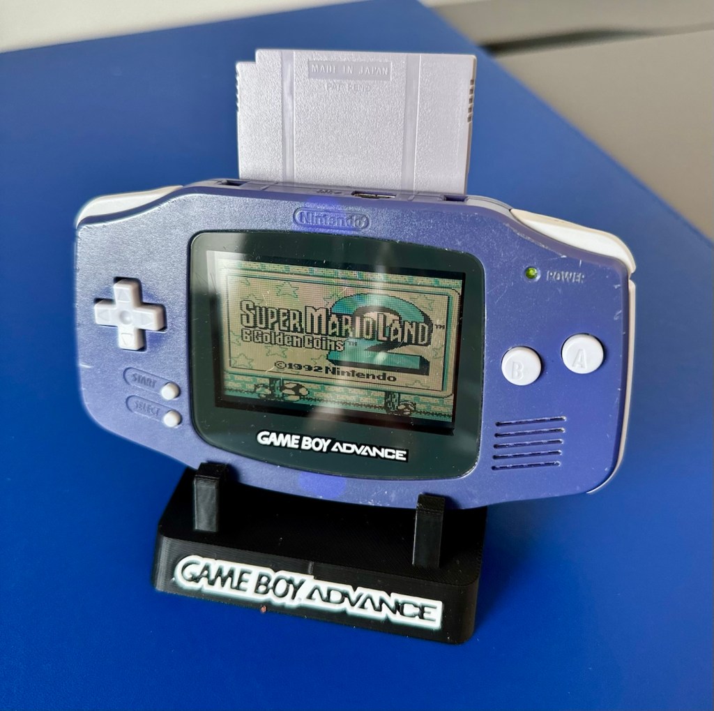
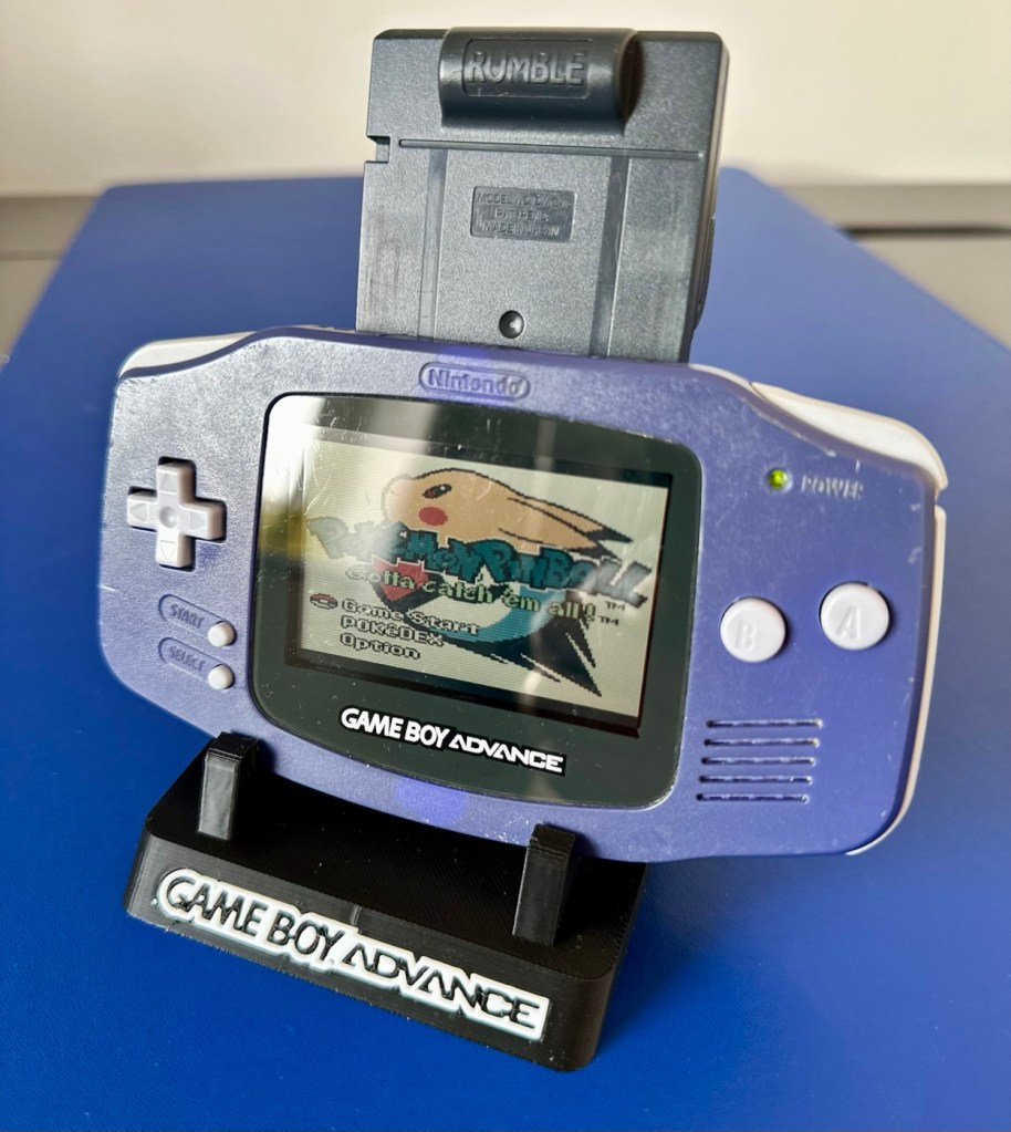
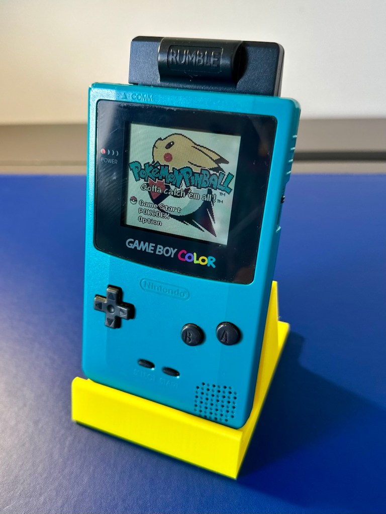
And here we are. The original unit has been thoroughly cleaned, it’s come up ok but is probably a good candidate for a case upgrade and a Capacitor change at some point. That’s just cosmetic though, what really matters is that this unit is now working perfectly, and it sounds just fine.

This unit actually came from a guy who restores these units, I guess he was just having an off day as to be honest, it wasn’t the most difficult issue to diagnose and repair. It honestly took longer to clean this unit than it did to repair it. I’m pleased that I’ve used all the original parts and just been able to do a proper restoration as such.

81 million of these units were produced, so this is just one in that 81 million, that has been saved again from landfill to be enjoyed for many more years to come.

Thanks for passing by. Always most appreciated.

Nintendo Gameboy color console

I’ve purchased a faulty Gameboy Color for my collection. It has no power, so let’s have a look and try to get it working again.

What the listing stated:

Very clean, but doesn’t turn on

EBay

Yep. It’s a Gameboy Colour to me, but as it was sold using the American spelling of “Color” then that’s what it will be addressed as, going forward.

I’ve been after a “Color” to add to my collection for a while now, but it had to fit my very strict quality requirements, in truth it just has to be faulty, and this particular example has met my conditions. I’ve paid £30.00GBP for this example and I’m happy with that, it’s a very fair price.

The good news seems to be that it is in a really good condition, it looks as if the battery door is missing, however they are freely available and this is not an issue should I require one.

These units are known to sustain power failures and the repairs are well documented. By now the unit is close to 30 years old and as time advances components start to fail, these include, but are not limited to:

  • Power switch failure: either a complete failure that requires replacement or quite simply a simple clean to remove years of tarnish and environmental gunk.
  • Fuse failure: there are two fuses F1&F2 that are known to fail, normally due to a short somewhere else on the circuit, but sometimes due to a power surge or incorrect addition of an incorrect power supply.
  • Via failure, small through the board connectors that are known to suffer with corrosion, requiring intervention with the addition of small wires to bypass the issue.
  • Capacitors – known to fail on a regular basis, it’s sometimes good housekeeping just to get these replaced as they are a contributing factor as to why other components such as the fuses also fail.
  • Worst case scenario: major corrosion or main board component failure.

We’ll cross these bridges when and if we need to.

Here’s a little info about the Gameboy Color console:

The Game Boy Color (abbreviated as CGB or GBC) is an 8-bit handheld game console developed by Nintendo. It was released in Japan on October 21, 1998, and in international markets the following month. Compared with the original Game Boy, the Game Boy Color features a color TFT screen instead of monochrome, a CPU running at up to twice the speed, and four times as much memory. It is backward compatible with games developed for its predecessor. The Game Boy Color was released during the fifth generation of video game consoles and competed with Bandai’s Japan-only WonderSwan, SNK’s Neo Geo Pocket Color, and Sega’s North America-only Genesis Nomad.

The handheld is slightly thicker, taller and has a smaller screen than its immediate predecessor, the Game Boy Pocket, but is significantly smaller than the original Game Boy. As with its predecessors, the Game Boy Color has a custom 8-bit processor made by Sharp. The American English spelling of the system’s name, Game Boy Color, remains consistent throughout the world.

Wikipedia

So, for now, let’s not speculate on its quality and issues until it arrives, when we can then carry out a proper assessment of the unit that has been received.

Assessment:

The package has arrived. The battery lid is missing as kind of expected, I will get a replacement sometime, but for the moment I’ll probably print one out on the 3D printer, it’ll be a totally different colour as I don’t have a “Teal” coloured filament to use. The product label on the rear is also damaged but I can easily get one of these as a replacement, however it’s not essential and will only be of cosmetic appeal.

Missing battery cover and old product label

The front fascia is in a good condition with only a minor scratch on the screen, however there are a couple of dents and dinks on the body where it looks as if it’s been dropped or bashed at some point.

Front fascia is good

All ports, switches, buttons and sockets look ok and seem to be operating as such with no resistance or signs of stickiness.

Again, the casing is in general fit to use, and in no way causes any issues with its operation when working. It is purely a cosmetic issue that i can address when the unit is finally working.

I have installed two AA size batteries, switched the unit on and it is most definitely dead. Repeatedly flicking the switch does nothing at all, so it is a situation where the unit will have to be opened up and further investigated. The assessment has not thrown up any other issues not already highlighted in the sales documentation, so in general I am quite happy with the outcome at this stage. let’s get inside and see what we can find.

Oops. Wasn’t expecting that. I’ve removed the six “tri” screws and as soon as I’ve separated the two halves, an amount of what looks like battery corrosion “crap” has fallen out as well.

Oops – corrosion is present

With the two halves separated, I then remove the screen ribbon cable, remove three more screws and the main board lifts out.

There’s some good news here. The contamination looks as if it has been completely isolated to within the battery area, there is no sign of any damage to the Vias, or any other components on the main board.

I have obtained the schematic diagram for this circuit board for checking continuity, and i’ve been able to confirm there are no issues with any contamination damaging any traces to the board. We’ve been very lucky here, dodged a bullet, to coin a phrase.

Schematic diagram

I have removed a set of battery contacts from the battery area, and replaced these with a new set that I have in my spares box. I could clean these, but it’s good to remove all items that were originally contaminated and very possibly contributory to the fault we have today.

I have also cleaned the front and rear of the main board with IPA just to ensure that if there was any issues with contaminants on the board, they’ve now been removed.

The switch has been tested electrically with a multimeter and this is working fine. The three capacitors have been looked over and seem to show no signs of wear or deterioration, they haven’t been properly tested though, so let’s now check fuses F1 & F2.

For reference: Fuse F2 protects the DC jack, whilst F1 protects the battery compartment. Using the continuity mode on the multimeter, a continuity through the fuse should present an audible buzz that let us know the fuse is complete and has not failed in any way.

I start on F2 and get a healthy buzz that tells me F2 is working fine. However fuse F1 is a different story, there is no continuity and there is no sound, I check again and can confirm that this fuse has blown, maybe this is a result of the contamination that was in the battery area?

The two fuses, F1 is dead

I’ve now attached the bench power supply supplying a 3v input to clarify the fault.

A 3v supply proves the fault

Fuse F2 has a 3v supply on each side, however our suspect fuse F1 only has a 3v supply on one side confirming that this fuse has blown. Once this fuse has been replaced I can check the voltage supplies on the remainder of the board, especially on the DC-DC regulator board, that supplies varying voltages from 3v – 13.6v required around the main board. On the main board the voltage regulator can be recognised as U5.

DC-DC voltage regulator U5

A quick check for short circuits doesn’t show anything of concern, maybe when the fuse is replaced it may well open up some other issues, the fuses I will be using are “resettable” fuses. These fuses seem to be the standard now for these units. Most resettable fuses—known as Polymeric Positive Temperature Coefficient (PPTC) or polyswitches—reset automatically and do not have a physical reset button. Once the underlying overcurrent or fault condition is removed, you simply disconnect the power source to allow the fuse to cool down, then you switch on again, if the same issue occurs, there is an obvious issue present that needs investigation, as stated above, once the faulty fuse is replaced I will be able to check other areas on the mainboard for correct voltages.

Just for information the fuse that needs replacing is approximately 4mm in width. You can see the scale in this picture taken alongside a ruler.

The tiny suspect fuse

Let’s get on with the repair.

Repair:

First off I’ve printed a replacement battery door cover. As stated earlier I don’t have any “Teal” filament so I’ve printed it out on a purple filament. For the purposes of practicality (holding the batteries in place) it will serve a purpose whilst carrying out the repairs.

I have a replacement fuse, this work will now have to take place under the microscope as it’s just so tiny, think grain of rice size and you will understand just how small this component is, and it’s amazing that a component so tiny can completely shut down a unit such as this.

The supplied fuse is even smaller than the one on the board. If the original was 4mm then this one is probably around 1-2mm it really is minute. Here’s a comparison of them side by side on the microscope base.

Tiny and teeny tiny….

That said I’ve removed the old fuse, wicked away the old solder and applied some flux and a couple of new dabs of solder. Compared to these new fuses the solder looks massive, I can assure you it isn’t and is greatly magnified.

With the bench power supply providing 3v I’m able to use the multimeter to confirm that the fuses are both working, however there is another issue and I suspect it is something I discussed earlier, but omitted to heed my own advice, about good housekeeping. I’ll come to that in a second.

Power is getting around on the 3v rail and is not an issue. However at the Dc converter I’m not getting the 5v or 13.6v rail, so there is another issue. The new fuse has dropped out again, and this is good as it proves it works. I let it cool for 30 seconds and it is back up and working and I’m able to continue tracing the fault. The big capacitor C32 that sits beside the DC-DC converter appears to be carrying a short, it is probably this that has caused the fuse to previously fail.

And my good advice was to change these capacitors for good housekeeping purposes…..and I didn’t.

Guess what I will be doing next?

There are three Capacitors on the main board and below you can see what their primary functions are:

  • C32 (Main Power / DC-DC Filter)100µF, 6.3V (Filters the incoming voltage; if faulty, the system won’t boot or will repeatedly reset).
  • C35 (LCD Display Filter)22µF, 16V (Stabilises the voltage to the liquid crystal screen; if faulty, it results in a dim or washed-out image).
  • C38 (Audio Amplifier / Sound)100µF, 4V (Powers the speaker and headphone output; a failure here is the leading cause of whisper-quiet audio).

Ok. Fortunately I have plenty of capacitors in my spares box so I was able to replace the three capacitors with no issue.

This done I then decided, prior to any reassembly to see if the power was now being distributed as it should, and I’m pleased to say it is. We have the full range of voltages now coming out of the DC-DC converter.

Now let’s get the unit reassembled, cleaned and then get some tasty pics taken👍

Result:

To finish it off and whilst the 3D printer was still warm, I’ve printed a simple brightly coloured yellow display stand to show it off on.

A new printed display stand

After a good clean the unit is now in a perfectly good working order. The fault appears to have been the faulty capacitors and battery contamination all probably combining to make the power fuse fail, a perfect storm if you like. The fuse and three capacitors have now been replaced to breathe new life into this game console. Cosmetically it’s still tatty and would probably benefit from a new outer shell and some labelling, however it works and to be honest that is all that really matters.

A small video showing the unit working

I wonder how many of these items just get thrown away because they don’t work? This probably took me about three hours in total with diagnostics and repair. Another piece of retro history restored, now joining my original Gameboy classic as part of my collection.

It’s been a pleasing little project, enjoyable and educational and it’s always good to hear the familiar beeps when it springs back into action.

Another one saved from landfill.

Thanks for passing by, as always it’s very much appreciated.

Dell Axim X50V Handheld

A pocket computer from 2004 that needs a little attention. Let’s get it working.

What the listing stated:

Dell Axim X50V Handheld PDA with Windows Mobile 2003 SE. The PDA is in a used working condition and  advertised as for spares or repair due to a faulty battery cover switch, It is also missing its rubber feet and SD slot cover.

The Battery has recently been replaced.

Comes complete with the following.

Desktop Cradle

Power Supply (Damaged lead, please see photo)

Windows Mobile 2003 Second Edition Companion CD

3D Game Pack for Dell AXIM X50V

Please see photos for overall condition.

EBay

Here’s some info regarding these units:

The Dell Axim X50v was a high-end Personal Digital Assistant (PDA) released in late 2004. It was a flagship device in the Axim line, notable for its advanced multimedia capabilities, specifically its VGA screen and dedicated graphics accelerator.

Key Technical Specifications

  • Processor: 624 MHz Intel XScale PXA270.
  • Display: 3.7-inch transflective VGA TFT color display with \(480 \times 640\) resolution.
  • Graphics: Intel 2700G multimedia accelerator with 16MB of dedicated video memory.
  • Memory: 128MB Intel StrataFlash ROM and 64MB SDRAM.
  • Operating System: Originally shipped with Microsoft Windows Mobile 2003 Second Edition.
  • Expansion Slots: Dual slots featuring one CompactFlash (CF) Type II and one Secure Digital (SD/MMC) slot with SDIO support.
  • Connectivity: Integrated 802.11b Wi-Fi, Bluetooth 1.2, and Infrared (IrDA).

Features and Performance

  • Multimedia & Gaming: The Intel 2700G chip allowed for smooth 3D gaming and high-quality video playback, which were advanced for its time.
  • Design: Compared to previous Axim models, the X50 series featured a sleeker design with rounded edges and a curved base.
  • Battery: It uses a user-replaceable 1100 mAh Lithium-Ion battery.
  • Software Upgrades: While an official upgrade to Windows Mobile 5.0 was released, some users found it ran slower than the original OS due to the slow NOR flash memory used in the X50 series.

Multiple on line sources

Let’s await its arrival to see what we have.

Assessment:

The package has arrived, very well packaged. I have enough bubble wrap now to to last for quite some while.

The item turns on, and appears to be doing what it should and then without even touching the back of the unit, an error appears on the screen.

A common fault apparently

On the cable directly from the charger unit there appears to be some damaged cable sheath. I have tested the power output and flexing this area does not cause any interruptions to the power supply, it appears to be that only the external earthing of the cable is exposed, so I am happy that it will be fine to just apply some heat shrink tubing to this portion so that the cabling inside is no longer exposed. It looks as if at sometime someone has probably used a knife instead of the correct tooling to access the unit.

Exposed earthing

There are a couple of rubber feet missing, that just so happen to cover screws that allow access to the unit, further strengthening my suspicions that this unit has been previously accessed internally.

Missing rubber feet

The battery is new, and is holding a good charge of 4.16v at an indicted 100% indication, and it is rated at 3.7v so this appears to be a healthy battery.

Battery holds a good charge

Cosmetically this is a nice unit for its age, it has a stylus pen included, along with a charging cradle and original software that came with the unit. There is a small SD card slot cover that is missing, however this is not an issue as I will probably install a small SD card to fill that void. It can also take CF cards and there is also a blanking plate installed to fill that portion of the top of the unit.

Let’s get repairing…

Repair:

I’ve gone straight in at the charger cable and have chopped the offending portion out. I’ve had to do this to be able to get some suitably sized shrink tubing in place. With the wires exposed I strip them back, tin them with some solder and, then finally connect them back together ensuring they are suitably insulated from each other, and safe and secure. It doesn’t look pretty, but it’s safer than it was.

I’ve tested the output with a multimeter and the output is around 6 volts as stated on the power pack, so no issues there.

With the charging cable all sorted it’s time to look at the error message problem associated with the battery latch.

The Dell Axim X50v battery latch often degrades, triggering a false “battery door open” warning or sudden sleep mode shutdown. If your device is frequently going to sleep on its own or reporting a false “battery door open” error, it is typically caused by a loose, dirty, or misaligned latch switch inside the device.

There are a number of options we can go through to attempt to alleviate this issue:

  • Clean the Contacts: Power down the device, remove the battery, and gently clean the small plastic sensor switch and surrounding contacts inside the battery cavity with a cotton swab dipped in isopropyl alcohol.
  • Mechanical Shim: Over time, the plastic door can warp, failing to press the microswitch down. By placing a tiny, folded piece of paper inside the microswitch channel to force it into the “closed” position. Then snap the battery door into place.
  • Permanent Bypass: For an advanced fix, you can bypass the switch entirely by soldering the connections or using conductive paint to bridge the gap on the motherboard, ensuring the system always thinks the door is closed.
  • Replace the Door or Latch: If the physical latch or door is broken or entirely missing, replacement battery doors can still be sourced from specialty PDA parts sites.

Taking the above suggested remedial actions into consideration I’m going to approach this repair combining two of the above suggestions. Firstly I will clean the contacts as in the first option, this is standard work practice for me. I will probably use a contact cleaner rather than IPA in this instance. I will ignore suggestion number two, as that’s a temporary “Bodge job” fix that should only really be used to test for an issue. The third suggestion of the permanent bypass is what I will use should action number one not be successful, the error is one of those pain in the butt errors that are really unnecessary, and serve no real purpose at all, so let’s permanently disable its ability to reappear. The door itself is in a good order and does not require replacement therefore cancelling out suggestion number four.

So. To recap I will go with suggestions one and three.

Let’s get going then….

Four small star screws are all that need to be removed to get the shell open. Inside everything looks lovely and clean and there sitting at the bottom of the main board is the tiny switch that is causing the issues.

The switch that’s causing the issues

Immediately opposite this switch on the battery panel switch is a small piece of felt that I presume was originally set in place to hold the switch down.

The tiny piece of felt

Well, it had moved and was sitting in the wrong place. I’ve cut a small piece of felt that I use for repairing light seals on cameras, cut this to size and placed it in the correct position. The small switch is like a rocker switch, I have cleaned this with IPA and it is now clean. A quick clean around the main board and now it is time to reassemble.

Now all back together, battery now in place and the unit switches on fine. A little shake of the battery panel cover, and no error message appears. In fact no error message appears until I physically open the battery panel, but once it is put back in place and locked it again, the fault clears. The repair as such has been successful. You can see in the picture below, the battery error at the top of the screen, that results in a restricted use, until it is cleared. A standard fault with these units, now repaired.

Everything is working fine on this unit, it voice records, the stylus is present and I have all the original software. It’s year 2K compliant and is working as good now as it ever has, the only items I have not replaced are the two small rubber pads used as feet. Not really necessary and if I ever find anything suitable, I’ll utilise it.

I’ve given this unit probably the best soak test it could ever be given, a rather long session playing original solitaire with my wife. She’s played for a little over an hour solid now and no error codes or faults have appeared.

I’m happy we have a good working item, resurrected from impending doom in a landfill. Let’s get it cleaned and finished off.

Result:

The unit has cleaned up nicely, and for an item that is 22 years old, pre smartphone technology, it has aged really well.

I just love these items from probably the best tech area there ever was, 90s through to year 2k and just beyond. Technology was developing, it was new and exciting with lots of choice unlike today.

It gives me a chance to now go back and buy the items I’d never be able to afford as a youngster/teenager, even though they may be broken. And that’s the fun of it all, learning, repairing and enjoying a momentary rerun of good times gone by.

I love it. And another item is repaired, saved from landfill and another piece of tech history goes on for others to enjoy for a few more years to come.

Thanks for passing by. It’s always very much appreciated.

Canon EOS 1D MkIV

Two late production Canon EOS1D MkIV cameras, both heavily used ex-syndicate sports photographers cameras. Do they work? Can they be repaired?

I’ve been approached by an old colleague who used to be a syndicated sports photographer, he had a number of items he wanted to “get rid off” as they were just taking up space in his new house. “Would you be interested?” You betcha, so as a result I’m now the owner of a complete Bowens lighting system, two Canon EOS 1D MkIV cameras and a Canon EOS 5D MkII camera.

My days of fussing and farting about with lighting rigs has now long passed, so I know a youngster starting out in the business who is a very talented young fellah, I have donated this equipment to him and he will certainly have a use for this lighting setup. He has been approached and accepted the offer, I think he is quite happy with his new acquisition, here’s hoping his talents continue to flourish.

However the cameras are mine as no one wants this old stuff anymore 😂

Having already in the past, repaired a film version of the EOS 1 here: Canon EOS1 N HS I have now become the owner of two Canon EOS 1D MkIV versions, the digital upgrade of this superb camera. This post covers the assessment of the 1D’s the 5D can be found here: Canon EOS 5D MkII

The two Canon EOS 1D MkIVs

To test these two beauties I’m going to have to invest some money into my equipment store. These cameras take a battery that neither came equipped with, an EP4 battery that currently costs around £19.00GBP per unit. On top of that a charger is required costing approximately £23:00GBP so there will have to be an outlay of approximately £42:00GBP just to get these units tested. Is it worth it? Yes, I think it is, I will then have a spare battery and charger for future use, and if the cameras don’t work? I can then sell them on or use them for spare parts as they have cost me absolutely nothing. When I go through the assessment and repair of these cameras I will refer to them one camera at a time. The camera that has stickers on the top of the camera pentaprism area will be referred to simply as “One” whilst the other will be “Two”. Nice and uncomplicated.

But first here is a little bit of information regarding this camera, the Canon EOS-1D MkIV.

The EOS-1D Mark IV is a professional 16.1 effective megapixels digital single lens reflex camera (DSLR) camera body produced by Canon. The EOS-1D Mark IV is the successor of the Canon EOS-1D Mark III and was announced on 20 October 2009, just four days after Nikon announced the D3s. It used to be the only Canon APS-H format DSLR to feature HD video recording at 1080p resolution.

It was discontinued in mid-2012 with the introduction of the Canon EOS-1D X, which replaced both the EOS-1D Mk IV and the EOS-1Ds Mk III.

It received a Gold Award from Digital Photography Review.

Features:

  • 27.9mm × 18.6mm; 16.1 effective megapixels APS-HCMOS sensor
  • Dual DIGIC 4 image processors
  • Canon EF lens mount (excludes EF-S)
  • New autofocus module (45 AF points with 39 cross-type AF points)
  • Integrated sensor cleaning system
  • 1.3× crop factor
  • 100–12800 ISO speed equivalent (expandable to L: 50, H1: 25600, H2: 51200 or H3: 102400)
  • 30–1/8000 sec. shutter speed and bulb
  • Shutter unit tested to 300,000 cycles
  • Auto Lighting Optimizer
  • Magnesium Alloy weather sealed body
  • Eye-level pentaprism viewfinder with approx. 100% coverage at 0.76× magnification
  • Live preview mode
  • 3.0 in, 920,000 dots Clear View II TFT color, liquid-crystal monitor with 160° viewing angle
  • 10 frames per second continuous shooting (Large JPEG: max. 121 frames, raw: max. 28 frames)
  • Dimensions (W×H×D): 156 × 156.6 × 89.9 mm

Wikipedia

Assessment:

I’ve had to bite the bullet and purchase a battery and charger to be able to test these cameras. Look at it as an investment. As promised the assessments will include exactly the same checks, but they will be done individually.

I want to check shutter counts and firmware versions, but to carry out these tests I really do need power in the units. Clock backup batteries are installed on these cameras and these will need to be checked to see if they are still effective as I’ve no idea how long ago they were changed.

Camera one:

Here are the pictures:

I can pretty much pinpoint the last time this camera was used, as in the CF card slot there was a 16GB card installed and when downloaded there were six photos on the card, below you can see two of these images.

The photos show a football ground, it’s the Queen’s Park rangers ground in London, and you can see the Stanley Bowles stand just to the right. The photographer is in the usual position where you would find sports photographers attending a football match. The exif data in the photo gives the date as 30th August 2022, and if you check records you will see that QPR were Playing Hull City that evening, and QPR were the winners 3-1. We have a date that informs us this camera was last used almost four years ago. Interesting isn’t it?

So of the two cameras this one seems to have had the hardest life, I very much suspect this one is the older camera (it is I have checked the Canon database and it’s construction date is June 2013, the second camera is October 2014) This date may seem contradictory due to the fact the production run officially ceased in 2012, It is very possible for a Canon EOS-1D Mark IV to have a 2014 manufacturing date, even though the camera was officially withdrawn in late 2012. Professional cameras often have long production runs that continue well after their retirement date. Cosmetically it appears the most beaten up and used, with a number of old press pass stickers in the pentaprism area. There are no signs though of deep gouges or cracked and damaged metal so I’m confident this camera has not been dropped. It has had a tough life. It’s a tough camera though.

The CF card and SD card holders are both in a good condition, both accept cards without having to use any force and all pins are in a good condition, I’m confident there are no issues in the memory card area.

The clock battery is accessible at the point where the main battery fits in to place.

The battery is a CR2025 lithium coin cell. When tested the battery has a value of 3.028V. This is a sufficiently good charge for its purpose and is good seeing that this camera has not been used for the last four years.

Holding a good charge

Moving on I’m looking in the lens barrel and the pentaprism and both mirror and viewfinder are extremely clean and clear. The rugged, bruised exterior has protected the delicate, clean and tidy interior. It certainly is a very well constructed camera.

All lovely and clean inside

The next thing I do is test the actual workings of these cameras, however that can’t be done until later today when the battery and charger that I ordered a couple of days ago arrives.

The battery and charger has arrived:

It’s here!

First thing I have done is to put the battery in its uncharged state, into the cameras just to see if there is life and the news is good with both. This Camera, number one has the following information.

Camera one information

It was the most beat up camera and it does have the highest shutter count at 283,976 actuations, the shutter life cycle of these cameras is 300,000 actuations as tested by Canon, so it is a very high count but still has a bit of life in it before it reaches the potential shutter count ceiling.

The good news is that this actual camera does have the latest firmware update of 1.1.5 so at least that doesn’t have to be downloaded and installed.

Battery now fully charged I have finally been able to put this camera through its paces test wise. And hells bells I’m so impressed. It was already set in quick fire mode so when I pushed the shutter button I was shocked to see just how quick this camera responded. It was rattling off shutter actuations at a breath taking 10 frames per second, wow, the sound was amazing!

10fps mode….impressive

It’s not hard to see why you can get such a high shutter count on these cameras with such shutter activity, it absolutely makes sense why these cameras are used in high speed activities such as sport and wildlife photography.

All displays are working as normal, all button actions and dials are doing exactly what they should be doing. This camera is in a good healthy condition.

As an older camera it is packed to the rafters with settings and possibilities, there is so much to learn around its operation, its capabilities and settings. It’s built like a tank, weighs a ton, makes a lot of camera noise that I relate with the good old days and I just absolutely love it.

Even the shutter bumper foam is in good condition and does not require replacing yet.

Camera two:

Here are the pictures:

Camera two is only 16 months younger than camera one, and you can see that difference in cosmetic condition immediately. The wear and tear on this model is considerably less than that found on its counterpart. This camera had no CF card inside so there was no way of putting a last used date on this one.

As with camera one there are no signs of the camera being dropped, no damage to the metal casing being cracked and no sharp dents visible. The Cf card and Sd card holder both take cards without any force having to be applied, and all pins are in a good order. I’m confident there are no issues in the memory card area.

The clock battery reading is a very low 4.5mV it is very dead. I have therefore replaced this with a CR2025 3V lithium coin battery reading a lot healthier 3.30V.

Clock battery reading, before and after

Again as in camera one, the viewfinder and mirror are both very clear and the lens barrel is very clean, having been protected by the rugged camera exterior.

Weird face in the mirror – it’s clean though

With the new battery that had just arrived installed, it kicks into life and I am then able to get the following information from the camera.

Camera two information

This camera in comparison to Camera one has a really low shutter actuation count of 72,186. The tested shutter count by Canon is 300,000 actuations, so this camera still potentially has a lot of life left in it.

The camera firmware will need to be updated to the latest firmware of 1.1.5 as it currently has a slightly older firmware installed of 1.1.0.

Ok, I’ve downloaded the firmware file and extracted it to the CF card I’m using in the camera. Let’s get it installed.

The camera firmware is now updated.

As in camera one, with the newly charged battery installed the immense high speed of the shutter is highly impressive. All buttons, dials and switches function as they should and all displays are clear and sharp in appearance.

All serviceable parts remain in a good condition, even the mirror bumper foam is in a good state and does not require attention yet.

Repair:

I’m now going to condense this section into a mix of both cameras. It’s a bit of an anti climax for anyone wanting to see a meaty repair post as that’s just not going to happen here. Both these cameras, though used and in one case extremely highly used, have both been maintained and looked after during their life. So for me my job has been easy, and going forward I will just maintain them in a similar manner.

A quickly shot image indoors

I see absolutely no point in tampering with them now, they are working just fine and are in a perfectly good condition. Their construction is so solid with their metal weather sealed bodies, that the last thing I want to do is compromise that construction and security just to fill space in a post..

A quickly shot image outdoors

All I’m going to do at this point is polish both cameras. Camera one with its beaten up body and press pass stickers is just going to stay like that, I want that to remain as a constant reminder of its use, and its purpose as a high usage press photographers camera, it’s a work of art in itself and that’s how it will stay. Camera two, again will jut be polished, it’s the more acceptably presentable “Cosmetically” camera and with its lower shutter count and will probably be the unit i will concentrate on using myself.

A few pics from the two of them:

I’m only using very basic test lenses on these units and I must admit, even with basic optics the visual returns are quite impressive. The colours are so rich, and I love that there is also the setting to do some pure black and white shots if you so wish.

This is my new (Old) favourite camera. Why do I just fall in love so easily ❤️

When these cameras first came out they were commanding a price of around £4,000.00GBP and people were more than happy to pay that cost.

Here I am a few years later and I have been gifted two of them for the grand old price of…..Nothing.

I’m a lucky old fellah I’d say.

Result:

I present to you, two wonderfully heavy, cumbersome, noisy and beautifully constructed pieces of photographic history, and both are an absolute joy to behold.

My new long term relationship has just begun (Don’t tell the wife 😂) and I am so looking forward to getting these cameras out to a sports or wildlife watching event. To many, I know they will say, why do you want to carry one of those around, why not go mirrorless? Well, I’ve got that gear as well but I hardly use it. I’m an old 80s-2000s guy who loves the old technology, just like I love old noisy aircraft, I love to hear a camera working, it puts a smile on my face. And the chances of me owning one of these beauties when they first came out was an absolute zero. Now I have two, and I have some serious catching up to do.

Thanks for passing by, as always it’s very much appreciated.

Stay safe.

Canon EOS 5D MkII

My second chance at reviving a DSLR from 2008, the Canon EOS 5D MkII. Will I have a little more success with this one?

I’ve been approached by an old colleague who used to be a syndicated sports photographer, he had a number of items he wanted to “get rid off” as they were just taking up space in his new house. “Would you be interested?” You betcha, so as a result I’m now the owner of a complete Bowens lighting system, two Canon EOS 1D MkIV cameras and a Canon EOS 5D MkII camera.

My days of fussing and farting about with lighting rigs has now long passed, so I know a youngster starting out in the world who is a very talented young fellah, I have donated this equipment to him and he will certainly have a use for this lighting setup. He has been approached and accepted the offer, I think he is quite happy with his new acquisition, here’s hoping his talents continue to flourish.

However the cameras are mine as no one wants this old stuff anymore 😂

This post focuses on the repair of the Canon 5D MKII, the repair of the EOS 1D MKIVs can be found here: Canon EOS 1D MkIV There is also a link to my first attempt at a Canon EOS 5D Mk2 and here is the actual assessment of that camera and the issues experienced with it Canon EOS 5D MK2 assessment and repair, I failed with this repair due to it having sensor issues, so sold it on at a small profit, i’m hopeful that this new attempt at the 5D will bring better results.

The Canon EOS 5D MkII

Let’s hope this camera acquisition comes with a better outcome. Whereas the other two 1D cameras i received in this package have required me to to purchase a new battery and charger, I do already have a number of LP-E6 batteries and a charger in my possession, so there is no initial outlay required to test this camera. We are off to a good start here and should be easily able to diagnose any issues fairly quickly.

Anyway, before we assess the camera, here is a little bit about the Canon EOS 5D MkII.

The Canon EOS 5D Mark II is a 21.0 effective megapixel full-frame CMOS digital single-lens reflex camera made by Canon, the first Canon EOS camera to have video recording capabilities. It succeeds the EOS 5D and was announced on 17 September 2008.

On 2 March 2012, Canon announced the camera’s successor, the Canon EOS 5D Mark III. On 24 December 2012, Canon Japan moved the camera to their “Old Products” list, effectively discontinuing the camera.

The Canon EOS 5D Mark II is a full-frame camera and requires Canon EF-mount lenses. It is not compatible with EF-S lenses (which are for APS-C crop sensors).

Features:

  • 21.0 megapixels (5,616 × 3,744 pixels), compared to 12.8 megapixels (4,368 × 2,912 pixels).
  • DIGIC 4 image processor, compared to DIGIC II.
  • 100 to 6400 ISO (expandable to L (50), H1 (12800), H2 (25600)), compared to 100 to 1600 (expandable to L (50), H (3200)).
  • 3.9 frames per second continuous shooting (78 JPEG or 13 Raw in a single burst), compared to 3 frame/s (60 JPEG or 17 Raw).
  • Small Raw modes: sRAW1 mode (10 megapixel/3861 × 2574 pixels), sRAW2 mode (5.2 megapixel/2784 × 1856 pixels).
  • 98% viewfinder coverage with 0.71× magnification, compared to 96% coverage.
  • Larger 3.0-inch (76 mm) LCD with 920,000 pixels, compared to 2.5-inch (64 mm).
  • 1800 mAh LP-E6 battery, compared to 1390 mAh BP-511A.

New features

  • Movie recording full HD at 1920 × 1080 and SDTV at 640 × 480 resolution.
  • Monaural microphone for audio during video recording, speaker for playback and microphone jack for external stereo microphone
  • Live preview with ExpSim LV “exposure simulation” live preview (full exposure preview control utilizing ExpSim LV, a first for video in a DSLR)
  • Live preview with contrast-detect autofocus
  • HDMI video output for live preview or playing clips and images on an external monitor via Type C MiniHDMI port
  • Dust reduction system to perform automatic sensor cleaning
  • Battery management software

Key Lifespan Factors:

  • Shutter Rating: 150,000, though this is considered conservative by users.
  • Real-world usage: Many cameras show failure rates increasing closer to the 100,000–150,000 range, but many exceed it significantly.
  • Longevity: Some, though rare, individual cameras have recorded over 2 million shots.
  • Repairability: The shutter mechanism can be replaced if it fails, which may extend the camera’s life further.
  • Component failure: Other parts, such as the power board or rubber grips, may fail before the shutter. 

Common Issues:

  • Rubber grips: Rubber grips can become loose over time.
  • Button/Dial functionality: Buttons and dials may wear out over long periods of use.
  • Sensor maintenance: Regular sensor cleaning is needed to maintain performance. 

The 5D Mark II is the first camera in the EOS line to provide video recording functions. Still photography during video recording is possible, but the camera suspends recording video until the final still frame is captured.

The lithium-ion battery for the 5D Mark II (LP-E6) has an 1800 mAh capacity. Each battery contains a microchip with a unique identifier for reporting charge status and battery health for display on the camera. The 5D Mark II’s “Battery Info” screen can track battery health and shooting history for up to six LP-E6 batteries.

The camera has native ISO values of 100 multiplied by a power of 2; other ISO values are obtained by a digital exposure push (ISO values that are multiples of 125) or digital exposure pull (ISO values that are multiples of 160). The digital exposure push ISO is 1/3 stop greater than the native ISO, and a digital exposure pull ISO is 1/3 stop less than the native ISO. The digital exposure push ISO settings produce more noise than the native settings with a reduced dynamic range, and the digital exposure pull ISO settings produce less noise than the native settings.

Wikipedia

Assessment:

The camera has arrived and here are my first thoughts. But first some pictures.

Just holding the camera and looking around it, you can see it has been well used over the last eighteen years. There are chips and scuffs, but nothing excessive, and certainly no “hard” dents that would indicate it has been dropped at anytime. The top LCD panel has a scuff on it, but this doesn’t stop any information being read.

The battery contacts are clean and there is just a small rubber cover missing on a connection that is on the base of the camera. All switches and buttons appear to operate as intended, everything is there and the exterior appears to be used, but in a good condition.

The lens barrel appears to be clean, the mirror and focus screen have a little dust and dirt on them however this is an easy clean. The shutter is closed underneath the mirror ensuring the sensor stays isolated from the outside world. I won’t be able to check how this is until I have a battery installed.

Batteries. As I have stated above I do have compatible batteries for this camera. This camera has a battery management system installed that communicates with the original “Canon” batteries that report back on their charge status amongst other information. However my batteries are not Canon originals and are in fact third party ones that don’t have the ability to communicate as original batteries would. That said, they are more than capable and usable. I just know that the very second I put the battery in and turn the camera on, it will show some kind of battery communication error on the rear screen. It’s ok though as we can opt to ignore that warning, click ok, and just get on with things, with no issues to the general operation of the camera.

Let’s do a little digging around. I’ve downloaded a little program that appears to be quite popular, to try and find exactly how many times the camera shutter has been activated in its lifetime, (still photo count – not including video). Here is that count.

243,487 shutter activations…wow!

I guessed the count would be high as it was the previous camera of a syndicated sports photographer, I just wasn’t quite expecting this high. But who am I to complain when I have received this camera for free. if you read the camera specs in the paragraphs above, the expected lifespan of the shutter is around 150,000 actuations, however the photographic community tends to question this figure. Some cameras have gone into the millions with shutter counts, however this one will plod on with me on much lower figures, if I get it working. I don’t know its service history, it’s a rugged built heavy use camera, that will go on for years if looked after properly. And that’s what I intend to do with it.

Another piece of information that can be obtained from the piece of software above is the firmware version. The current installed version is 2.0.7 and that was installed sometime in 2010. The latest and last version is 2.1.2 that was released in 2012. I will attempt to update this cameras version of firmware to the final updated one.

I think I’ve had a good assessment with this camera, I know what needs looking at so let’s get on with giving it a little TLC to ensure it will go on working for a few thousand more shutter actuations, I’ve got to try and get this camera to the 1/4 million mark at least!

Repair:

The first thing I want to do, is to look into why, when you input a date into the camera, the information disappears as soon as the camera is turned off and turned on again? This is a simple issue, easily located and soon rectified. These cameras normally have an additional battery buried somewhere in the camera that acts like a cmos battery in a computer. It simply supplies a small charge that maintains dates and program settings when the camera is an a sleep mode, instantly reinstating the correct information when the camera is switched on again.

And this camera is no different.

A single coin cell CR1616 battery is what does the job in this camera, its life span is usually around five years. So let’s check this one out as I suspect it has failed. It is located on the bottom of the camera on the opposite side of the main battery chamber, below two rubber accessory panels.

The CR1616 battery is a 3v lithium coin cell. Using a multimeter I was able to confirm that this one was well and truly depleted as it was only holding a charge of 99.3mV. The new battery cell was holding a much more acceptable charge of 3.3V.

Old and new battery voltages

With the new coin battery in place, I’ll reset the date values and test that the battery is doing its job, by powering the unit up and down a few times.

That appears to have worked

As you can see in the picture above, I’ve managed to update the settings, and when the unit is shut down and restarted the information remains. Hence the new clock/cmos battery is working fine.

Next let’s try to update the firmware to the latest release. This small video below shows how easy this task can be. This particular file in the video is for an earlier, older update, however the principle is exactly the same for all camera updates with Canon.

Updating firmware on a Canon Eos5D MkII

Following the recommendations in the video above I have downloaded the latest firmware update file and extracted its content to the freshly formatted CF card for the camera.

It’s thinking about it….

The whole process was followed exactly as laid down in the instruction video, and it went as expected. The update was successful.

Firmware update, before and after

The camera is now correctly updated to the most recent firmware. I can now progress to doing some final checks in the lens barrel area prior to moving on and checking the functionality of the camera with a lens in place.

The mirror bumper felt is in good condition and does not need replacement. I have blown out the barrel and inspected the sensor and that is clean and needs no attention.

Final touch is that I have printed off a cover for the hotshoe flash holder.

Printed hotshoe cover

Time to get the battery installed in the camera, along with a formatted CF card, and I’ve also put a stock 28-80 EF lens on the front to test. And here are some of those pictures taken to test, just around my garden.

And I am so damned impressed. It’s only a basic lens but the tonal quality, sharpness and colour has really shone through. The camera has worked perfectly, I’ve used it in auto mode, shutter priority and aperture priority and all works fine. When I use the video mode, all is fine but the basic lens when you telescope, can be heard throughout the video, not really an issue just an observation, hence why people invest in the higher end optics. For testing purposes though, this lens has performed perfectly. I’d be more than happy to venture out for a picture session with this setup.

Every setting on this camera has been tested and it has passed with flying colours. My job here is done.

Result:

A far better result than my last attempt on this specific type of camera. This time around the sensor has performed perfectly and remains in good order, hopefully for quite a time yet. It would be good to see it go through the 250,000 exposures count, and seeing that it’s only about 6,600 exposures away I don’t foresee it being a hard to achieve target. I’m going to get some good use out of this camera, I’m currently looking at taking it to a local nature reserve to see what can be photographed. I’m quite looking forward to that.

A final polish and this project can now be put to bed. Onto the next one.

Many thanks for passing by, it’s always very much appreciated.

TTS IT00617 digital camcorder/camera

I purchased these three damaged Camcorder/Cameras for a very low price. Will they be fixable or just good for spare parts. Let’s see…

What the listing stated:

TTS IT00617 Digital Camcorder Camera 

Full HD pocket camcorder that records in 1080P and can take 5 megapixel photos.

2″ TFT colour screen. Charges via in-built flip-up USB plug.  

Cameras appear to be faulty. One has a corrupt screen, the others boot and show the camera feed but give a “card error” no matter what SD card I install. 

EBay

The seller wanted £10:00GBP for these three camcorder/cameras but I was not prepared to pay that, for what potentially could be three pieces of junk, only good for parts. So I cheekily put in a £4:00GBP bid that was accepted straight away, the seller really wanted rid of these, I suspect they are junk, we’ll just have to wait and see.

From the information I can find that is available online, these units are handed out to children partaking in key skills programs within schools, to use when recording project work they are completing as part of the school’s curriculum. From what information I can gather, it appears these units were introduced around 2014, as that’s when the instruction manual is dated. They may only be around 12 years old but I suspect they have had a very hard life in those few short years. Hence they are very probably knackered, mistreated, and may well be just junk. My expectations for these units are now very low. The company that produces these units – TTS appear to be based in Nottinghamshire, near me in the East Midlands, and specialise in supplying ICT equipment to primary schools. Here is all the information I could find regarding these units.

The TTS IT00617 is a 1080p Full HD digital camcorder and camera specifically designed for educational and outdoor use by TTS Group. It is often marketed for use in primary schools due to its rugged design and simple interface. 

Core Specifications

  • Video Resolution: 1080p Full High Definition.
  • Still Image Quality: 5.0 Megapixel sensor.
  • Display: 2-inch TFT colour screen.
  • Zoom: 4x Digital Zoom.
  • Storage: Uses removable SD cards.
  • Connectivity: Includes HDMI and USB ports for connecting to computers or displays.
  • Power: Powered by a rechargeable Li-ion battery, which is user-replaceable. 

Key Features

  • Rugged Design: Built to be resistant and ideal for outdoor photography and video capture.
  • User-Friendly Interface: Often includes a built-in microphone and a touchscreen for easy navigation.
  • Educational Accessories: Retail packages typically include an installation CD, user manual, and necessary cables.

Google

I have managed to get hold of a user manual electronically, so I will download this and just go through the motions step by step when the units arrive. You never know one or two of them may just spring back into life if treated correctly. I doubt it, but it doesn’t hurt to have a little bit of optimism.

Let’s get an assessment done.

Assessment:

The cameras have arrived. I’ve carried out a very quick inspection and all three are dead to the world, so first things first, let’s try and get some power into them and then we can do a proper assessment. I must admit though, all three cameras are cosmetically in a very good condition.

All three cameras – two charging with red light visible

A switch on the side allows the USB charge port (also a data transfer port) to pop up and you just plug the unit into the socket of your choice, either a hub as I have, or into a port on your chosen computer device. When charging a red light shows on the rear of the camera at the side of the lens. This extinguishes once a full charge has been reached.

Two have reached a stage of full charge, one, the unit with the corrupted screen issue has not, and to check the battery, i have put this into one of the units that charged ok, to check if it is a battery issue or a unit issue.

It’s not a battery issue, in fact the faulty unit is charging its battery, so at least I know the charge circuit is working. It’s working in all units as I have removed all batteries and checked their voltages with the multimeter. The battery rating is 3.7v and they all currently hold a charge between 4.16v and 4.19v and that shows that they are all quite healthy.

Battery charge indication

All testing done, and now with an idea of the issues, let’s move into repair mode.

Repair:

The original posting stated that two of these units had “Card error” faults no matter what SD card was used, and one had a corrupted display screen.

I can definitely confirm that one unit does have a corrupted screen, and this is the same unit that was having the charging issues mentioned above.

You will see in the pictures above, that I believe the screen is actually ok, yes the output is corrupted, however the start up screen or the waiting screen show no such display errors. I suspect there is an issue with the actual camera module, so I will have to open this one up to investigate further. The on off button allows you to turn this unit on, however you can’t power off. You have to remove the battery to close the unit down. This is obviously another issue that requires further investigation.

The other two units with the “Card error” fault have each had a 1Gb SD card installed and no such error occurs. Well, to be honest, it actually only happened once, briefly on one unit, when I inserted a fresh card. It then asked me to format, which I did and then it was all normal, that’s all it required. I don’t know what type of card the seller was using, maybe they just did not format the SD cards, but as it stands the stated problem is non existent in these two units.

Two units, no issues working fine

With the two working units I am able to video, and take still photographs, they are working fine, there are no issues and I will display a small video and some pictures below in the result section. Don’t expect quality, it really is quite a basic system. I need to do nothing to these two units now, as they are working fine.

We now need to turn our attention the one failed unit with the corrupted screen, and power on and off issues. I’ve opened the unit up and had to use my microscope on this one as there was nothing obvious on inspection.

I detached the ribbon cable and removed the screen, I then repositioned it and again turned it on with the same result. I’m confident the screen is ok, it now looks like it could be an issue on the board.

I’ve now started to inspect the components at a magnified level, as some of these components are honestly a quarter the size of a grain of rice, they really are minuscule. The on/off button appears to be ok, it is covered in a dollop of rubber gunk that they use during production to protect parts of the circuitry, it’s all over this board. Having located the camera, I’ve now started to do some testing on the components surrounding it, and there is a short circuit detected on a small capacitor, and the four or five other capacitors surrounding it. I removed two of these capacitors and the short still remained, and that’s when I noticed the chipset sitting directly above it.

AN SPCA1628A-HL141 integrated circuit

On the screen I was now looking at an SPCA1628A-HL141 integrated circuit. This circuit is heavily used in cameras, digital video devices, and image processing equipment due to its image processing capabilities. And with the amount of failed components around it, I very much suspect this component is carrying the fault, it needs replacement, however as this entire unit has only cost me around £1:30, I don’t believe it’s financially viable to pay around £5:00 for a replacement chip, costing more than the combined three units. It’s just not worth it, and the gain from its repair would not match the outlay, it’s just not worth repairing.

Therefore this unit is going to be dismantled for spare parts, I have a battery, a battery control unit, a camera, an SD card holder, an LED screen and numerous other parts and screws that are far more valuable to me for future use. Very little will be wasted. What is disposed of will be recycled.

So we have one failure but we have two perfectly good working units. Two out of three ain’t bad. (I’m sure that’s a song!) – it is, Meatloaf – I believe, good tune!

Result:

So here’s a few pictures and a couple of small videos taken with the two working units.

Small video of the two units playing back videos

The overall quality is between atrocious and very poor, but I guess for the purpose of school kids documenting activities it suits just fine. The video is on par with what you would have seen on phones of the Nokia era, maybe early to mid 2000s. The pictures in the right light settings are not too bad, but you do get more bad than good.

What can I use this for? God knows, it would be ok for doing a basic journal with, something to film a rehearsal situation with prior to using the good gear and doing it properly.

To be honest, I’ve a couple of young relations under the age of ten in Devon who might like these just to fool about with when they are out playing. At £1:30 per unit they couldn’t buy a decent pack of sweets for that, and this would cause less dental decay 😂

Anyway, it’s a good fix, more saved from landfill, so in my eyes the job is a good one👍

Thanks for passing by. It’s very much appreciated.

HP Jornada 540 Series PDA Pocket PC

I have two faulty pocket PC units that I can hopefully combine into a “Frankenstein” unit. Can we get at least one of them working again?

What the listing stated….mostly AI produced I guess?

Untested, no charger, docking station only by Hewlett Packard

32MB Jornada PDA 540 Series Pocket PC Windows & Docking is a highly functional device that comes with some amazing features. This device is perfect for individuals who desire a highly efficient PDA Series. The device is sold as untested and is compatible with the Windows operating system. The brand of this device is HP, which is a well-known brand in the tech industry. The PDA Series is HP Jornada and it comes with an installed memory (RAM) of 16 MB. The display size (pixels) and screen type are unknown, but it has a model number of 540. This device comes with a docking station that allows ease of use for individuals.

EBay

And this is my original old 540 (548) Jornada.

I just know this is going to be a challenge, and to be honest i will have two of these when this one arrives. This is the 16 mb version, released in Mid 2000, currently aged at around 26 years old. I’ve had a dead one sitting in one of my junk drawers for a couple of years now and I though it would be a good challenge to get at least one of them working again, another one of my Frankenstein projects if you must. I have no charger for these, the chargers are priced at a premium with the online pirate community, (Robbing swines!) so I will just have to make do. At least with the docking station that this unit has I have somewhere to start from. I suspect both batteries will be dead so I may have to use some jiggery pokery to get some power into their circuits to see if we can get any signs of life.

But whilst we await the arrival of this unit, here is a little bit about this PDA:

The Jornada was a line of personal digital assistants or PDAs manufactured by Hewlett-Packard. The Jornada was a broad product line that included Palm-Size PCs, Handheld PCs, and Pocket PCs. The first model was the 820, released in 1998, and the last was the 928 model in 2002 when Compaq and HP merged. The Jornada line was then succeeded by the more popular iPAQ model PDAs. All Jornada models ran Microsoft Operating Systems that were based on Windows CE.

Jornada 540 series

The HP Jornada 540 series, including models 545, 547, and 548, was released in July 2000. As one of the original Pocket PC platforms, it featured a 12-bit color display, 32MB RAM, and USB connectivity running Windows CE 3.0.

The Jornada 540 series was one of the original models of Pocket PC, when the platform was first announced. Sharing the Operating System, CPU and memory card slot of the 520 series, it featured a 12-bit display (originally advertised as 16-bit display) and USB connectivity. Two models were made available that were identical except for the amount of RAM. The 545 had 16 MB RAM and the 548 had 32 MB RAM.

Wikipedia

Assessment:

The old one I originally had is in fairly good condition, only displaying age related wear and tear. It has its original touch pencil, and is pretty much all there. Its battery (a 3.7v Li-ion) is very dead though (see pictures above) I have no means at present to see if I can charge the battery.

My original old unit

I have however found a charging alternative that will not break the bank. I have found a chap in Germany called Edgar, that runs a business selling cables and peripherals for older units, as well as more up to date systems, his shop is in Hannover and his company is: systemhauszakaria.com. I have managed to get a USB charging unit called a System-S USB Charging cable, that has the connectors required for this unit, and being a USB cable I can use a suitable plug for the mains supply , if required.

The System-S USB charger cable

The cable includes a data transfer cable that also fits the unit, however my main task is to try and get some power into these units.

Let’s give it a go.

I’ve used the new lead, left the unit on and monitored it for about 90mins, and it does appear to be taking a charge. An Orange light indicates that charging is taking place.

Charging unit

The unit displays as 100% charged with the charging lead in. when disconnected it drops to about 50% but within a couple of seconds it shows as 100% again, this could be a time delay of some sort whilst switching to the battery circuit.

At this point I thought it would be worth getting the back off again, to check the battery charge. If you remember earlier in this post, this old unit that had sat unused in my desk for the last couple of years and when last tested the battery was dead at about 0.5mA. However this is a transformation, as when the battery was now tested its voltage was 4.09v. Now, a 3.7v Li-ion battery such as this should have a max charge voltage of 4.2v, so in theory this battery is in quite good condition considering its age. There may be a little deterioration, however considering this battery is possibly 26 years old it’s held up very well.

Before charge, and after

The unit will be left for a while to see how the charge holds. 10hrs later, untouched and off charge, I can confirm the power is still indicating 100%, this pleases me as it shows the battery is still good and has a good life inside of it. Very pleasing for what is potentially a 26 year old battery.

The new unit has now arrived and I’m surprised it got here after being posted in a couple of old carrier bags, no padding just a couple of old bags. I suspect the seller wanted it off his hands, they probably had little faith in it ever working again.

However, despite this, the actual unit appears to be in quite a good condition. It’s free from dinks and scratches and both the unit and the charging cable appear to be in a good order.

The new unit and charging cradle

Now, the good thing is that both these units have their original touch pencils. This cradle has a cable connected to it and a USB socket, however that USB socket is for data transfer and not charging. To charge, the new System-S USB cable has to be connected in line. The cradle will then charge. And it looks as if it is doing just that.

This time i have connected the new unit and cradle to a Power bank charger to see if this works, and it appears to be doing just that. It drained the power bank quite quickly, it only half charged, I’ll have to put it back on the household power tomorrow to fully charge it and check its battery capacity.

Tomorrow has arrived and the unit has been on charge for a couple of hours and it is indicating as fully charged. Back on the bench with the back off I can confirm the battery charge is reading at 4.08v so it is pretty much the same reading as the other unit.

New unit and cradle with power bank charger

These two units are both of the 540 series however the newer one that came with the cradle has only 16MB of memory (The 545) whereas my older one (The 548) has 32MB of memory. It appears that HP created three variants in the 540 range and I now have two of them. The 545 had 16 MB RAM and the 548 had 32 MB RAM, the one that escapes me, the 547 was also a 32MB variant. (I’m going to have to get one now just to complete the set)

545 on the left, 548 on the right

Repair:

Less of a repair and more of a resurrection to be fair. I said it would be a Frankenstein project, and that’s exactly what it has been. Both units have charged well despite my concerns, they have been charged in a monitored environment and neither are showing signs of overheating, irregularities or any battery swelling or other issues. The battery management system on both batteries seems to be doing its job, and doing it very well.

I’m going to use this section to test some of the functions, to look at the installed program package and at the same time monitor battery usage along the way.

And as with all my projects, a thorough clean of the units is going to be carried out, it’s just got to be done.

But first I’m going to leave these units for a few days to see if the batteries drain.

Three days later

Three days later it’s good to see that when turned on, both units are holding a similar, slightly discharged reading that is to be expected. I’m pleased at this, and it appears that both batteries are holding out well and working very well after a long period of inactivity.

Left again for a couple of more days and both units are now prompting me to accept that the UK has now turned to daylight saving time, (as it has) and this is another good sign that shows that all is working as it should be.

What am going to do with these units? Please don’t ask me that as I just don’t know. I’m probably just going to use them for note taking, maybe for a to do list for my work room, but in reality they will probably just get stored in a sealed bag with some silica bags to keep them dry, until I either move them on or find another use for them.

Good job 👍

The package originally installed on these units consisted of the following:

  • Microsoft Pocket PC Suite: Pocket Outlook (Calendar, Contacts, Tasks, Inbox), Pocket Word, Pocket Excel, Windows Media Player (for audio/video), and Pocket Internet Explorer.
  • HP Productivity Tools: HP Home Menu, HP Task Switcher, HP Image Viewer, HP Backup, and HP Emergency Backup.
  • Third-Party & Utilities: LandWare OmniSolve Calculator, Developer One CodeWallet Pro (for passwords), AvantGo (for offline web browsing), and PeaceMaker (for infrared contact exchange).

One item I wanted to test is the infrared transfer ability between units. I’ve made a small file within the word program, set one unit to transmit on infrared and the other to receive. On sending the file, this task worked fine.

The transfer worked however both units have to be within a very close line of sight to do so, it just shows how much file transferring has moved on within the last 25 years or so. We have been spoilt.

These units are both working fine.

Result:

Full Microsoft CE package
Working as they should be

There are many uses listed for these units online including MP3 players and television controls. However, I think using as a to do list for my workspace is probably the most appropriate usage for me. I need organisation in my life, so what if I’m using technology from quarter of a century ago.

Why not?

Two perfectly good items saved from landfill.

Small victory, and that’s good enough for me.

Many thanks for passing by. It’s always very much appreciated.

Still Haunting

Yep, the Ghost radio service I reported on in August 2025 is still operating in the East Midlands and beyond

Back in August of 2025 I wrote of a radio station I had stumbled across on the DAB network. Ghost radio service.

It’s probably the post that has had the most views on my site, strange! And has been mentioned in numerous chat rooms and sites across the t’internet,

Because no one really knows what the hell it is or who owns it.

Here’s a few definite facts.

  • It can only be heard in the East Midlands, especially around the city of Leicester.
  • It has been heard out in suburban areas on the far outskirts of the city.
  • It is someone making ghostly groans and moans.
  • It is only on DAB networks.
  • No one appears to admit ownership
  • There is very little information on line.
  • 7 months after first being heard it is still active.

And it’s still active today. Here’s a video taken a couple of days back.

Spooky 👻

Digging around, checking the OFCOM site amongst many others, the only new information I can find is listed below:

Key Details About Ghost Service:

  • Content: The station broadcasts a continuous loop of a “ghost” moaning.
  • Origin: It is an avant-garde art project created by a multiplex owner to challenge conventional ideas about broadcast radio and demonstrate the efficiency of their MP2 encoder at low bit rates.
  • Platforms: Initially spotted on DAB (Leicester SSDAB on block 9B and Lubra SSDAB on block 8A), it has also been heard on FM (87.9 MHz) in areas like Billingham and Middlesbrough, sometimes switching to Christmas music.
  • Other Projects: The same entity operates another station on the same multiplexes called “Catalytic Converter,” which plays cat sounds.
  • Visibility: It has garnered attention from local listeners and YouTube creators such as Fox’s Den. 

And it mentions me. How quaint!

Thanks for passing by, have a great day. Thank you 🙏

Canon Snappy 50 automatic 35mm camera

A compact Canon 35mm camera from 1982. It doesn’t work, so let’s make it work!

What the listing stated:

In generally good condition but does not power up
Sold as spares or repair

EBay

I came across one of these a few weeks back and was just taken by the shape and aesthetics of it. However i wasn’t going to pay a high price demanded by the seller, so i just hung around and waited for others to come on the market. I have just purchased this camera with free postage for a total of £1:13GBP. I’m confused, the seller will basically be paying me to take it off his hands as postage will be at least twice the value of what I have paid today. Let’s wait and see if this sale gets suddenly cancelled, as I suspect it may well do.

Anyway here’s a little bit of its history:

Released in July 1982 and based on a new concept, this is a fully automatic 35mm Lens-Shutter compact camera.

The camera height was reduced by about 30 percent, giving the camera an oblong and unique form.

The camera uses active autofocus with a solid-state near-infrared beam. EE and the aperture are controlled electronically with a program. Metering range is EV 8.6 (f/3.5 at 1/30 sec.) to EV 15 (f/9.5 at 1/350 sec.). The shutter speed is set within a range of 1/20 sec. to 1/500 sec. to suit the film speed.

There is only two film speed settings. ISO/ASA of 100 or 400.

The built-in flash (Guide No. 11 at ISO 100 in m) must be turned on manually with a switch when the camera-shake warning lamp lights in the viewfinder.

Canon

I’ll just wait now to see if it turns up. I don’t know what the problem with it is, it’s just listed as a power up problem.

Well I’m shocked, I’ve received a postage notification so it is definitely on its way. Next stop…Assessment.

Assessment:

Well, it arrived, I’m shocked. It’s got to be one of the best packaged items I’ve ever received, never have I seen so much bubble wrap protecting an item that cost just £1:13GBP.

On top of that the sender has spent £3:45GBP on postage and charged me nothing. God I feel guilty now, least I can do is give him some glowing feedback.

Wow – And I paid nothing

Right, back to the camera. For a 44 year old camera it really is in beautiful cosmetic condition and needs nothing but a slight dusting to finish it off. But first I put in two AA batteries and can confirm it is dead. No life at all. Also, the film door is flapping about (So there was another issue!). I’m going to have to get inside this unit to see what is wrong. To be honest the unit is such a basic one, I suspect there isn’t a lot that can go wrong with it.

Repair:

The film door issue is a simple one, and if I didn’t have a ton of spare parts spread around the place, I’d be quite annoyed to say the least. It would have been either a case of making a new catch for the door or building some Heath Robinson contraption to secure the door, looking completely out of place. However, I just so happen to have a complete rear door for one of these cameras so hopefully it should be a simple swap out of parts.

But before I do this simple replacement, I need to get the top and bottom off of the camera to check where the electrical issues lie.

Taking the bottom off of the camera, the problem presents itself quite clearly. At the bottom of the battery chamber the negative wire has detached and needs soldering back into place.

Negative wore detached from battery chamber

I put the base back on and put two batteries into the chamber and the rewind motor instantly kicks in. We now have power. The shutter works and the winder motor operates as it should. When the rewind button is depressed the rewind motor kicks in as well, all seems to be good…..until!

The live supply to the flash was detached

I try the flash, and nothing. Not even the usual sound of the flash capacitor charging. Damn, I hope that capacitor isn’t dead! So now I have the top off of the camera and another problem presents itself just as clearly as the first. Not a problem here as I need the top off to replace the rear door.

Rear door hinge removed and replaced

The live supply to the flash had broken loose and this also needed re soldering, in fact I re soldered about eight wires in total as it seemed that the solder joints in these critical areas could possibly be fairly. They may not be failing, but whilst I’m inside why not just do this simple task to prevent anymore premature failings?

Batteries back in, flash turned on (it’s manual on this camera) and the check light illuminates. This camera is now fully operational.

Flash check light now illuminates

Result:

I’ve had a fairly simple repair here with some soldering and luckily, some spare parts available. These cameras are quite tricky to repair due to their compact build. Normally when you detach one part you have tiny springs and other parts that fly out, leaving you with a head scratching puzzle to add to your issues. However having dealt with these cameras in the past and having learned my lesson previously, I was very careful and took my time ensuring nothing occurred that would cause me any issues further along in this fix. I also open these cameras in a box, so if anything does fly out, it doesn’t fall onto a carpet disappearing into the pile, it just falls into the box, saving me the embarrassment of looking for a tiny piece of camera, that could be just about anywhere on the floor of that room. You learn from previous mistakes, I have, and i now have procedures in place to prevent such issues happening again.

All cleaned up and working
And neatly cased

We now have a lovely example of compact 35mm photography, rejuvenated, repaired and ready to get back to doing what it was designed for, creating memories.

And long may that last, another one saved from landfill, repaired, recycled and now with many more years of purpose.

Many thanks for passing by 🙏

PS5 DualSense controllers

When the youngsters of the clan, drop surprise repairs on you at family gatherings.

It’s great when one of the youngsters of the clan come up to you at a family gathering and greet you thus, “Oi, uncle Dave, have a look at this for us will you?” and then they just disappear into the crowd as I’m now holding a couple of items I’ve never been exposed to before, in this instance a pair of Playstation 5 Dual sense controllers. (I had to google to find out what they were!)

Here you go “Uncle Dave”

Apparently they don’t work, or are having difficulties, and it’s now down to me to find out what’s wrong.

Now I’m not a gamer in the true sense of the word. I like, and have repaired and own a good few hand held devices that have been featured within these blog pages, but I do not own a console, I never have. However I’m lucky in that I know a few people who do have these consoles, who I can go to and test how they are behaving, but the good thing is that these controllers can also be tested without a games console and just require a computer with a USB port, and I do have one of them, a clever move by the manufacturer me thinks.

First thing I did here was to plug them in to a USB supply to charge the onboard battery. Each one has a 3.7v rechargeable battery that should give between 6-12 hrs of activity depending on how vigorously the unit is being used. When charging it glows on and off orange until it is charged and then the glowing just stops. Both these units took about 2.5 hrs to fully charge, and they seem to both be holding a good charge seeing one of them, the black version has not been used for some time.

Let’s get them connected up to a PC.

A simple good quality USB cable is the communication method between the controller and the PC. Next, you go to the address: https://dualshock-tools.github.io and here is where you will be doing those checks on the controller that sits in your hand. Seeing I don’t really know what’s wrong with the controllers I have been trusted with, I think this is the best place for me to start my investigation as the site does do some good, and thorough testing.

I have two controllers to check so I start by plugging in the Black controller, clicking connect on the screen gets access into the memory of your controller and all the firmware detail and build date is displayed in front of you. Cool!

Just under where this information is displayed we enter the first series of tests, a bank of 8 basic function tests that check all bells and whistles (as such) are operating as they should. This Black controller passed all these tests with flying colours.

All 8 checks passed

The checks are thus:

  • USB controller: here the connection is tested a simple pass or fail
  • Buttons: all buttons have to be continually pressed until they turn green on the screen, a simple pass or fail
  • Adaptive trigger: the system puts a resistance on the two triggers representing various triggers on guns and switches experienced in various games, if there is suitable resistance here the result is a pass.
  • Haptic Vibration: this tests the vibration motors in the controller, if it’s working then it’s a pass
  • Lights: all lights on the controller are cycled through displaying the whole range. Simple pass or fail
  • Speaker: a tone is played through the built in speaker, a simple pass or fail.
  • Headphone jack: a simple test of the plugin headphone jack – pass or fail
  • Microphone: a simple test by blowing in the on board microphone checks if it’s working, a simple pass or fail.

And as stated the first controller, the black one has passed all of these tests. Impressive. The next tests are all centred around the two thumb pads, their return to centre position and their all around circular motion and their calibration.

The left pad was showing slightly off centre and I was able to make some minor adjustments via the program interface to correct this issue. The good news was that it is not a constant stick drift, and the mechanism does not require replacement, it is easily adjusted. With settings saved, disconnect the controller, reinstall it and re check the calibration and it should all be good. And it was. With minor adjustments made to this controller I am pleased to say it is working as it should, it is now repaired and will be heading back to its owner.

Now onto the second item, the white controller. I put this controller through the exact same testing protocol as the first one, all was going well until we got to the buttons section where this one failed. The down button on the left hand side of the controller is unresponsive, you can see this in the photos below

Failed test in the button section
Failed button highlighted on Controller and screen

All other tests on this controller were fine. Again there was a little drift on the sticks that I was able to adjust and they are now both as central as they can be, operating well through their whole range. I will go through the repair and retesting of this pad in the section below the YouTube video that I have highlighted below.

A while ago, if your game pad was playing up, there wasn’t really a great deal you could do apart from replace the thumb controllers if you were experiencing issues such as a little stick drift (when a controller is moving on its own accord). A bad case of stick drift would require you to change the controller mechanism. However, some very intelligent people within the gaming community have put together a number of packages to test your game controllers, but the one mentioned in the video below has been a game changer as such, as it also allows adjustments to be made and saved and thus extending the life span of the components within, thus reducing the need to replace and dispose of those components prematurely. Have a look, it explains the testing protocols and checks them against other programs.

The whole testing procedure checked and compared with other testing programs

Repair and retest

It’s a simple enough activity to get inside of the controller, some clips, and four screws get you inside the package, getting beyond this though to the controller buttons where we need to be is a little bit more in depth. So here we go…

I’ve dismantled the controller as I said I would, initially the process requires four screws removing, after you first gently prise off the black decorative plastic surround as in the pictures below.

When you remove these screws the next task is to gently prise the two shells apart that then reveal the base of the controller

Shell successfully removed

At this point the battery needs to be removed and that is a simple plug disconnection, the battery plate has a single screw in it that needs removing. Before you remove the battery plate there are four ribbon cables that need removing, if you don’t do these then you will probably tear them and need to replace them. Believe me, I have done this in the past and ruined the tiny microphone ribbon at the very front. It’s not expensive to repair, just an unnecessary expense. Don’t rush it. Another 3 screws removed and we can now take off the top cover and get to where we need to be.

Top removed exposing fault pad area to the left

As soon as the top was removed I could see the potential issue with the controller direction pads. The pads are a rubber base with a carbon pad that makes contact with the circuit board below. Sometimes a simple clean of these pads can be sufficient to regain a connection between the two, but in this case it was plain to see that the pads on both sides were both well worn and to be honest they both required replacement.

Normally a good clean with IPA will work

As stated I did give a clean to all contact points with a solution of IPA, reassembled and tested again with no change in performance, the fault remained. I will now need to purchase a new pad assembly and replace the film circuit board below them. Fortunately these are freely available and will cost no more than £6:60GBP to replace. And considering a new controller would cost at least £60:00GBP it’s worth the small investment to restore it.

I now just have to wait to receive these items and get them installed.

The items arrived just as in the photos above, and following the previous instructions to dismantle the unit, I have removed the old conductive film sheet and replaced this with the new one. I have also removed the silicone pads with the carbon inserts and these have also been replaced.

Now all I have to do once I have connected the ribbon cables is to get the outer shell back on the controller. Once this is done, I can log in and start the testing process once again, connect the controller to it and then commence a full test of its functionality.

And as you can see in the above photographs, this has been a successful outcome. Where the left hand side lower button had failed, the new conductive film has addressed the issue and this handset now has full functionality and is working as it should be.

Next I’m just going to do a re-calibration, to check that the sticks haven’t drifted in anyway. If we are in a good position, we can then class this repair as successful and then it can then be passed back to my nephew to carry on shooting aliens, and he can then continue his mission to save the world.

Result:

Two controllers have now been serviced and are both working well and within tolerance. They are about to be returned their owner so he can get them back into use, killing aliens and saving the world from a zombie apocalypse (or whatever he does with them)

Not having a lot of experience prior to receiving these two controllers, I was a little doubtful about where to start and what to check. However after reading up on them, and their operation, I was able to pick up a lot of advice and information regarding their manufacture and serviceability. I like to think that I’m well clued up on these items now as I can disassemble one in minutes, replace parts and reassemble without having any screws or parts left over ( Always a good sign 👍)

And to round things off I have now been given one of his friends controllers to repair as well, so I must be doing something right!

Thanks for passing by, as always it’s always very much appreciated.