
My First Meshtastic build

I recently wrote about a decentralised radio network called Meshtastic. Here I attempt to build my first Mesh node using a kit, and by also printing a 3d case.

I recently posted an article regarding a low power decentralised radio network that you can read about here: Meshtastic

That post was an introduction to the mode, this post is my first attempt to assemble and program the equipment, and to try to create a presence on the Meshtastic network.

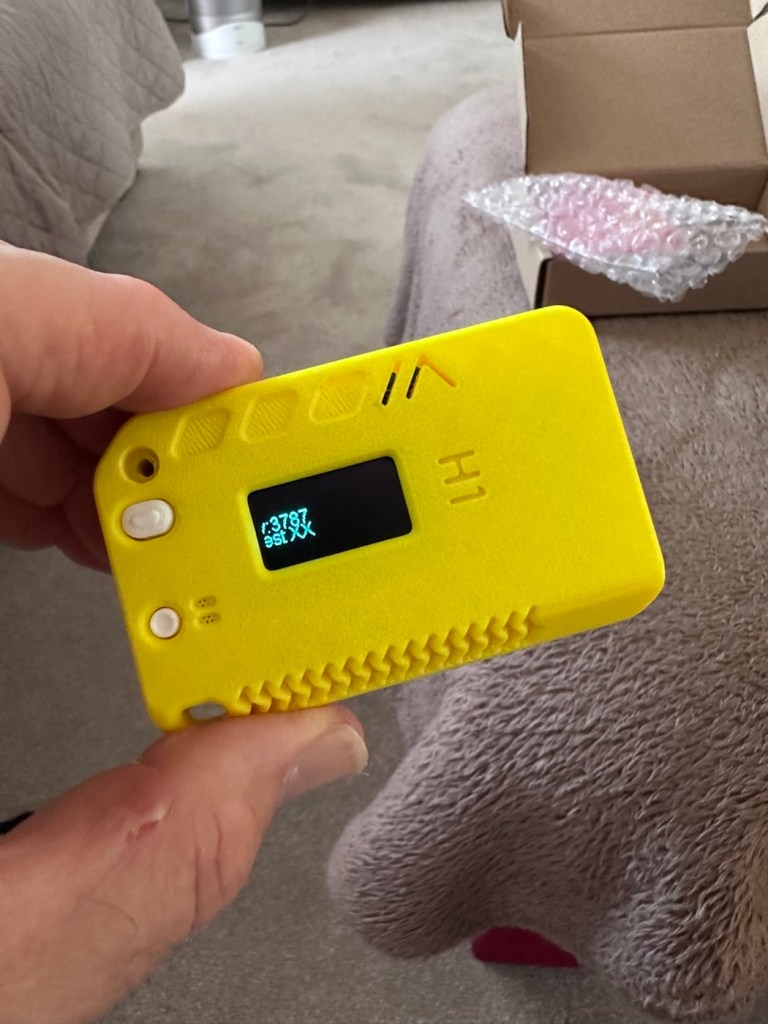
I’ve dived in and purchased a basic starter kit, the Heltec V3, and a separate GPS module, it’s my intention to install the GPS module once i get this up and working. The whole kit you see in the picture below is available in the UK and cost me a total of £34:19GBP. Other kits are available for a lower cost if you are prepared to await the delivery from China, however with my impatience on overdrive at the moment I just had to go ahead and buy it. That said i don’t think it’s too bad a price to pay for its combined parts.
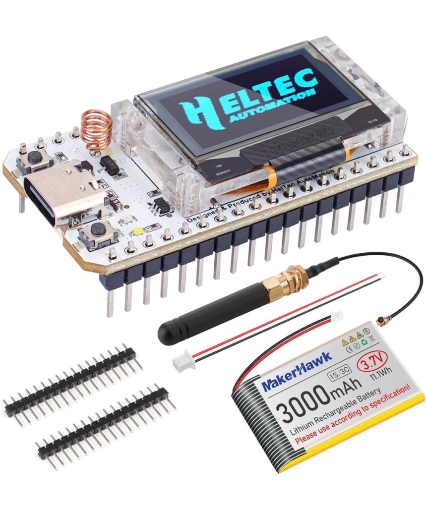
The purchased kit

Preempting the kits arrival, I’ve downloaded a case from Makerworld by a designer called: @gux2K3 that I’ve uploaded to my 3D printer, it’s a basic case, but this purchased kit should fit it perfectly. It might not be sufficient for when I get the GPS module, but I’ll cross that bridge when I get to it.
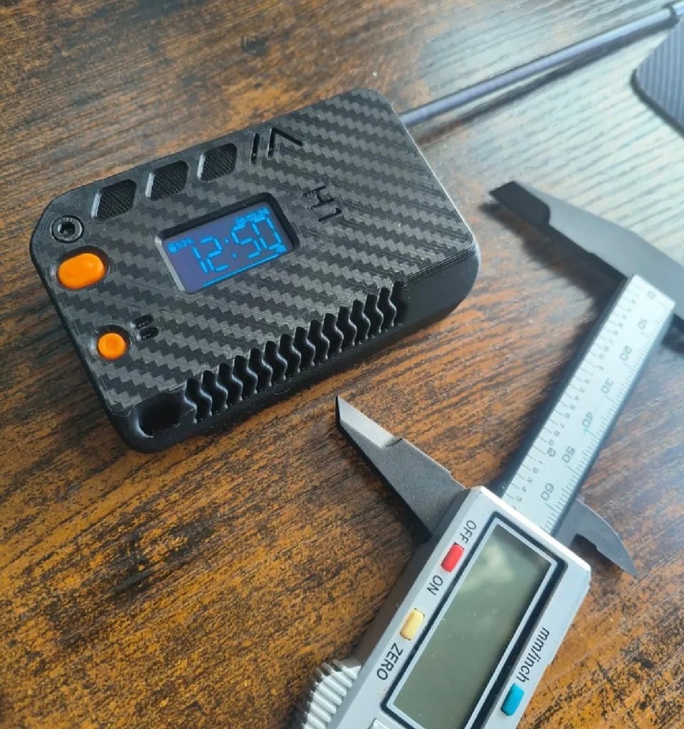
The original case design courtesy of @gux2K3
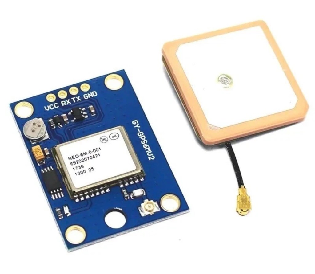
The GPS kit I’ve purchased

I have purchased the separate GPS module, and I will have to do some soldering to get this working. It will not fit in this case as I have already stated, so that upgrade will be saved for a later post.

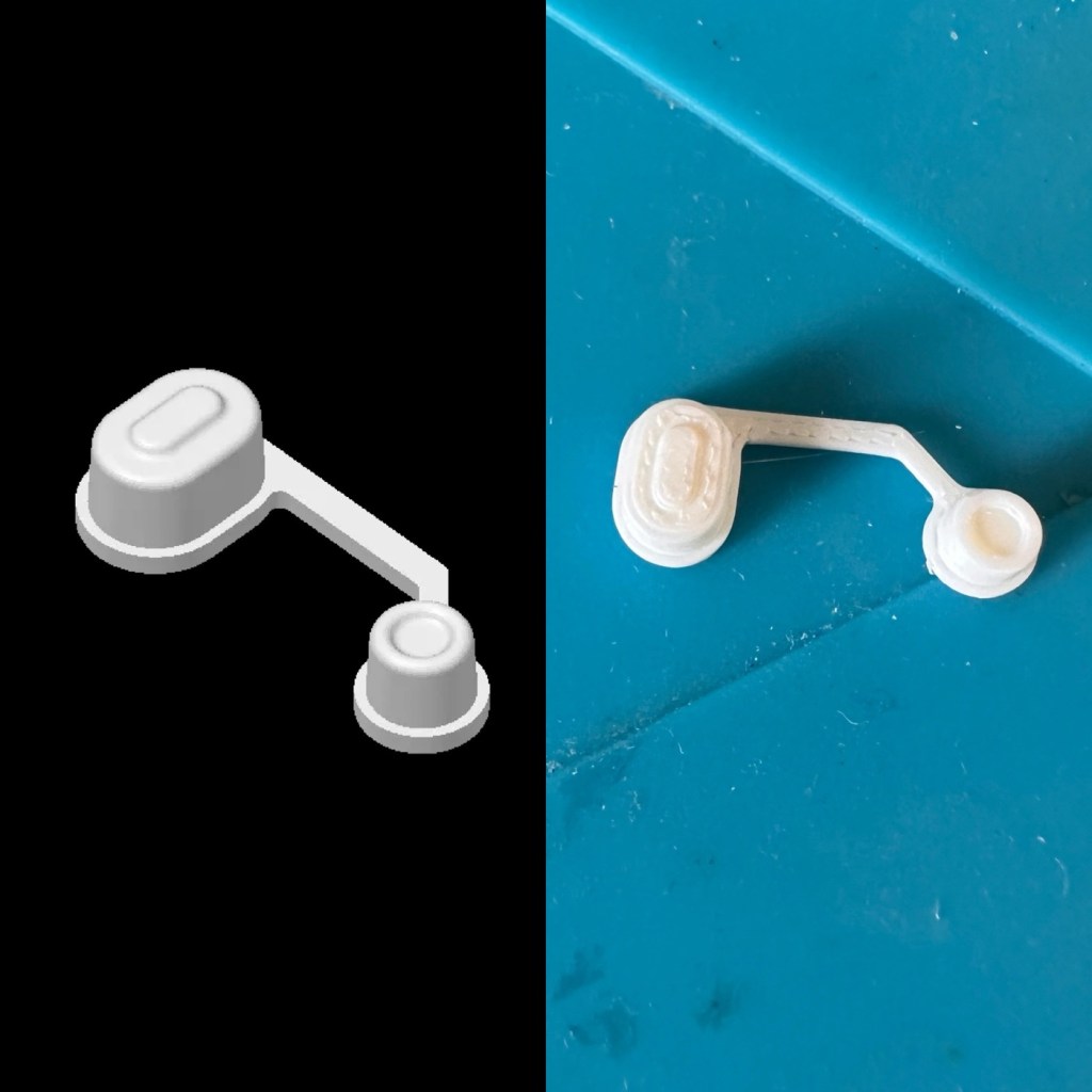
I want a basic slightly different colour scheme for my case, and below you can see a combination of pictures showing the original print plans and what the final piece looked like. It’s a three piece case, and I had to print this case on three different runs to get the different colours.
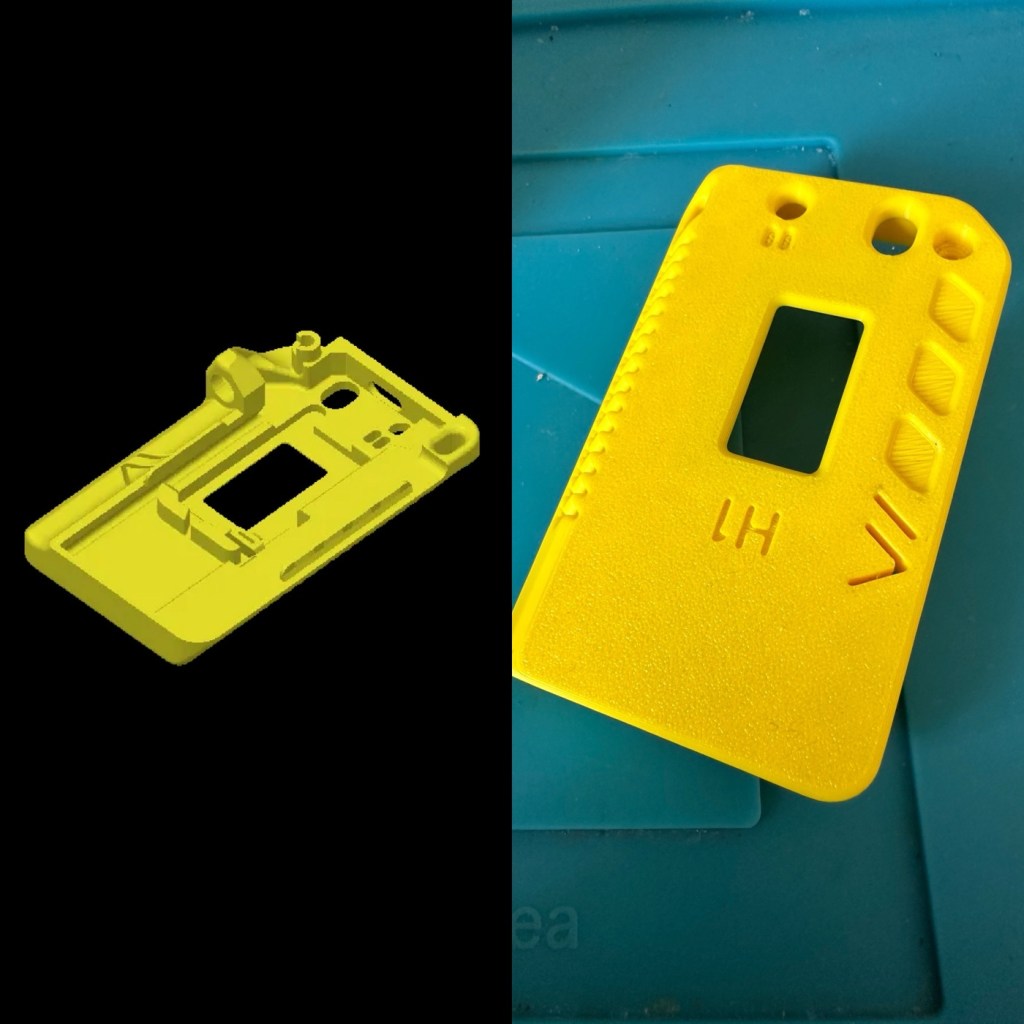
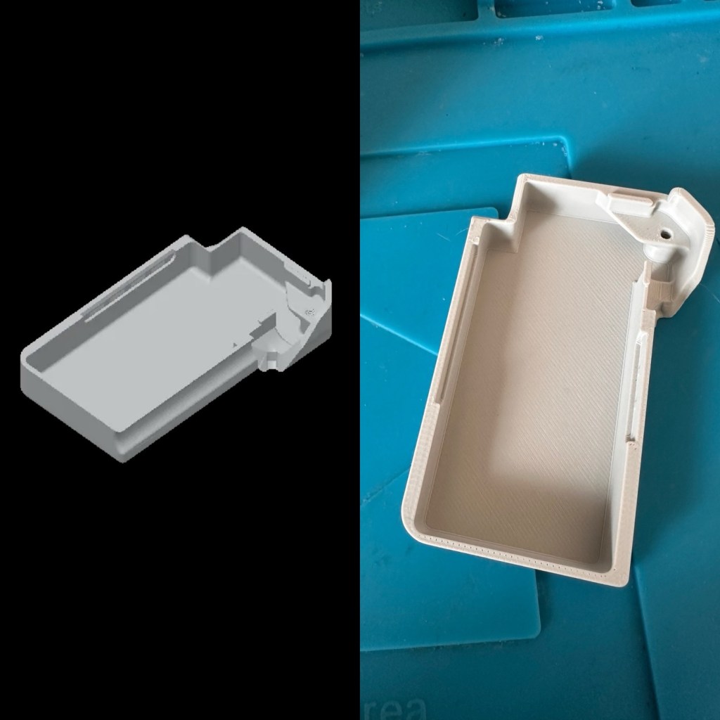
The finished case has been assembled I now just need to await the arrival of the kit for its installation.
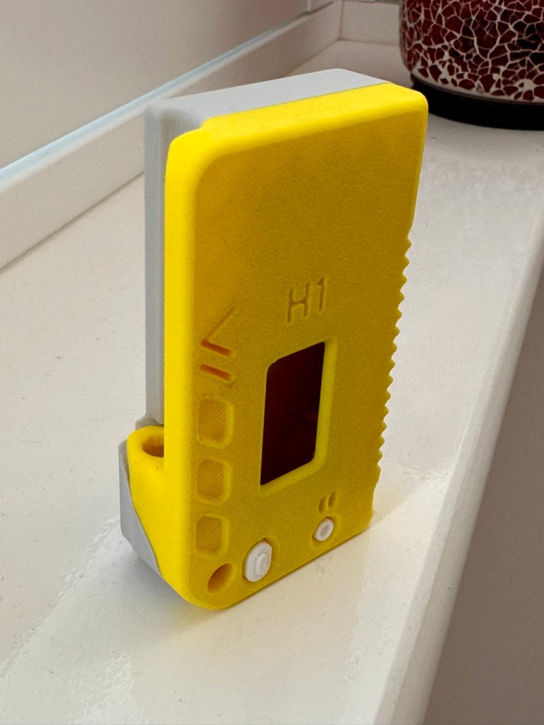
The finished case, just awaiting the electronics for inside

For those of you who haven’t referred back to my original post, here’s a very brief description of what Meshtastic is all about, there are also other choices and platforms to operate with using Meshcore and Reticulum as examples, so here goes….

Meshtastic is an open-source project that allows you to build decentralized, off-grid text messaging and GPS tracking networks using small, inexpensive LoRa radios. Operating on license-free frequencies, devices link together as a “mesh,” automatically passing messages from node to node without relying on cell towers or the internet. In the Uk Meshtastic operates on the 868Mhz band.

Because they are walkie-talkie style text networks, they don’t support voice or video, but they are fantastic for hiking, emergency preparedness, or team coordination. 

Other Off-Grid Mesh Options:

If Meshtastic doesn’t quite fit your use case, there are several alternative protocols and ecosystems built on the same underlying LoRa radio technology: 

  • MeshCore: A rapidly growing alternative. While Meshtastic acts as an “ad-hoc” network where every device handles forwarding, MeshCore allows administrators to set specific device roles like stationary repeaters or personal companion radios. This reduces network congestion, making it highly reliable for structured urban networks and tactical operations.
  • Reticulum: A highly advanced, open-source stack built for extreme conditions and censorship resistance. It is more modular than Meshtastic and supports multiple types of underlying hardware (not just LoRa), but it has a much steeper learning curve.
  • GoTenna: A commercial, plug-and-play solution. Unlike the DIY nature of Meshtastic, GoTenna pairs pre-built, proprietary hardware directly with your smartphone app. It’s easier for beginners but lacks the massive community, range expandability, and customization of open-source projects.
  • Amateur (Ham) Radio / APRS: If you are willing to get a license, Automatic Packet Reporting System (APRS) operates on designated VHF/UHF frequencies. It allows you to send text messages and GPS beacons over vast distances using commercial handheld radios (like those from Kenwood or Yaesu) via established infrastructure rather than a localized mesh. 

Assembly:

Ok. This isn’t that difficult and should be quite straightforward. The thing to remember is that the antenna MUST be attached to the board before power is applied. This is because the unit turns on and starts sending a signal as soon as power is applied, and without the antenna attached these units are renowned for burning out components for such a basically overlooked and simple step in the assembly process.

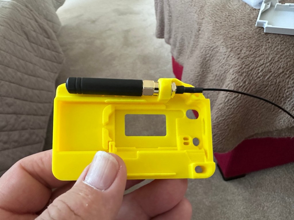
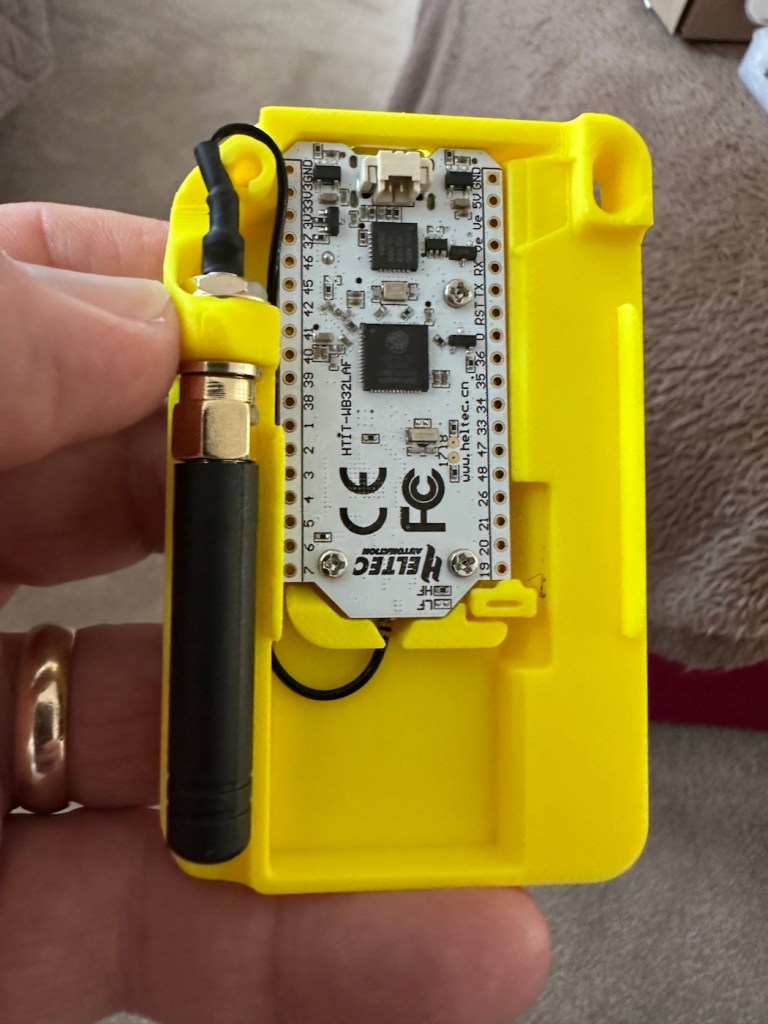
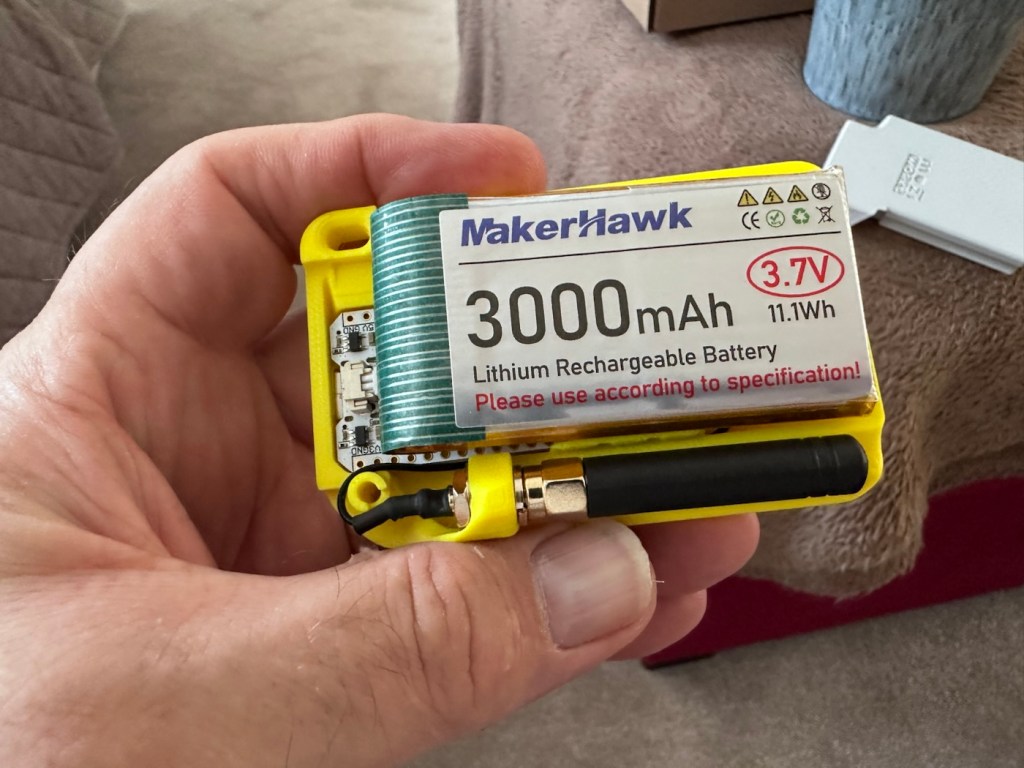
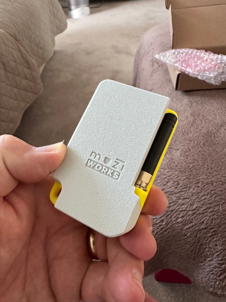
The whole thing is clicked together in about 5mins flat, the one task that takes the longest is the fastening of the aerial into the case. If you have sausage fingers like me, it can take a little time and a few attempts to ensure you get the screws set up correctly to ensure you don’t double thread the item. Here’s some pictures from unboxing to full assembly.
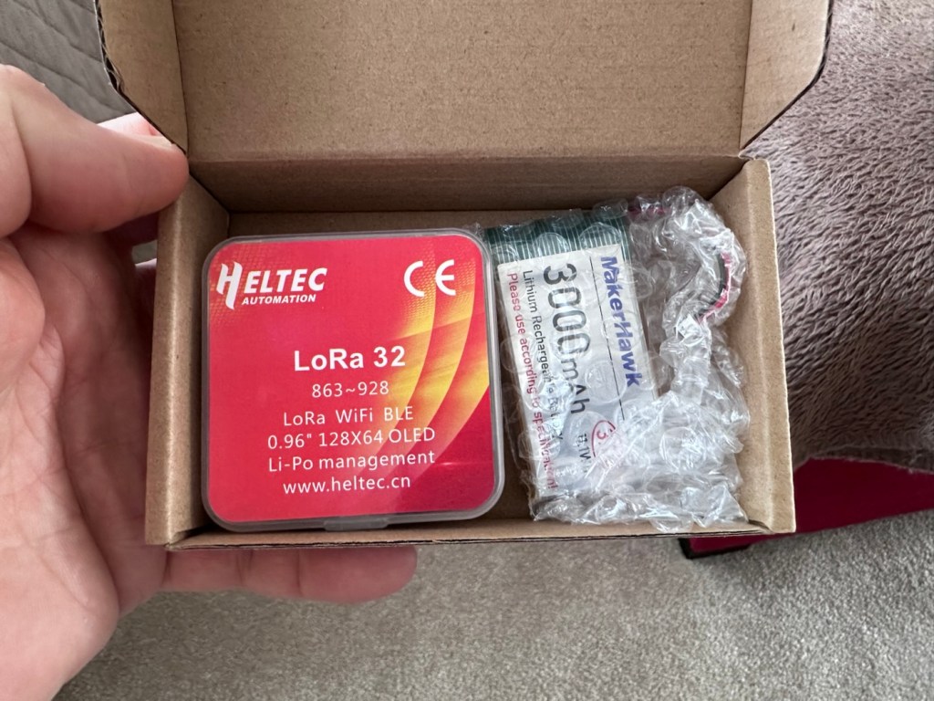
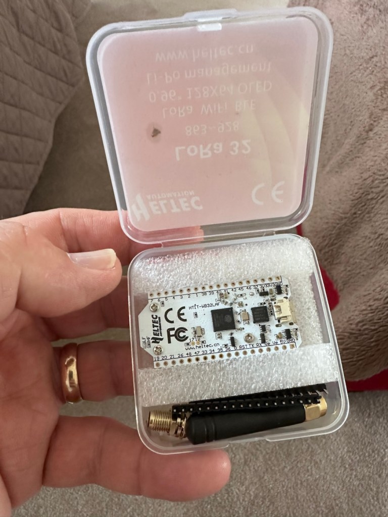
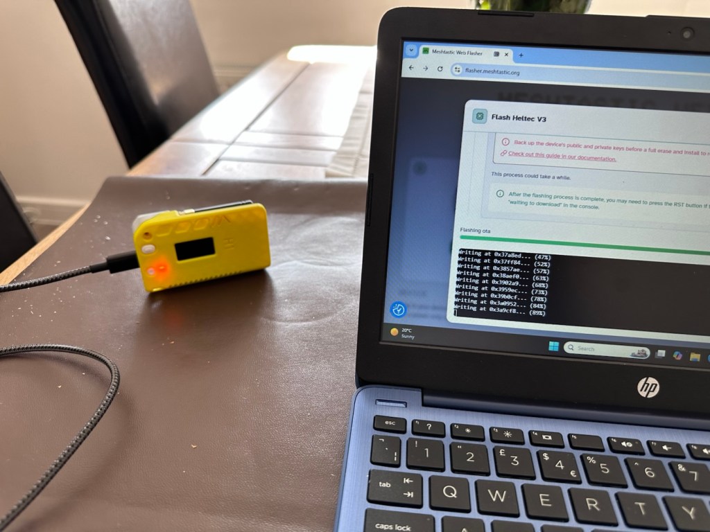
Once assembled the next thing to do is to flash the board with the correct operating software from the Meshtastic website. I’m not going to go into much detail with this as there are many good instructional videos out there that already have this covered, here’s one that I used to get me started:

Setting up Meshtastic on the Heltec V3

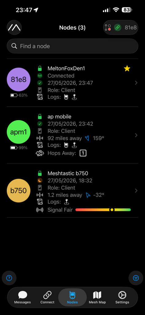
I’ve been using this node for around two weeks now, just testing its capabilities and seeing what the life span of the battery is. Here where I am in my part of the East Midlands, take up and usage at the moment is quite poor and in fact there is only one other node near me in use, and that one is being used infrequently to say the least. So for me, it’s just a waiting game to see if any other nodes appear as word gets out about the system, and basically if any is interested.

I have only made one contact within that time, a node that is about a mile away, and that’s it. There are so few nodes in my area, I believe i am only the third within a two mile range, and one of those is an unmonitored unit. but at least its a contact and proves the unit is working. It’s early days around here and a better mesh needs to be implemented. I’m sure in time as word gets about, and if anyone is interested that things will improve.

The thing of interest about this method of communication is that it’s purely off grid. Should every other form of communication cease for whatever reason then this is looked upon as an alternative for local “Meshed” communication. It’s a bit of a tin foil hat system in my personal view, I’m sure if someone in a position of power or tyranny wanted to shut the system down I’m sure that they could without too much trouble. It’s a good experimental system in keeping with similar practices that the Amateur radio network adhere to, however this system does not require licensing and is free for anyone to experiment with. And that’s the interesting part.

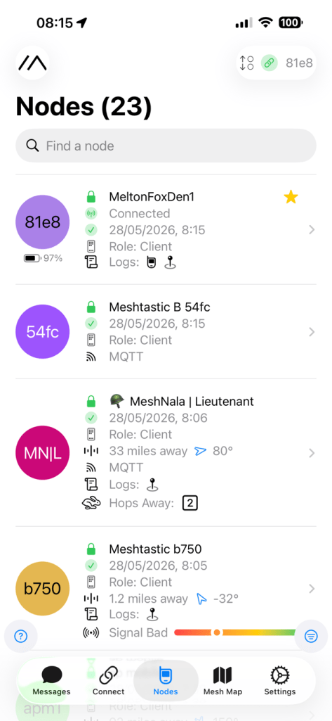
With the battery charged, and the system active my first “listening” session shows the following:
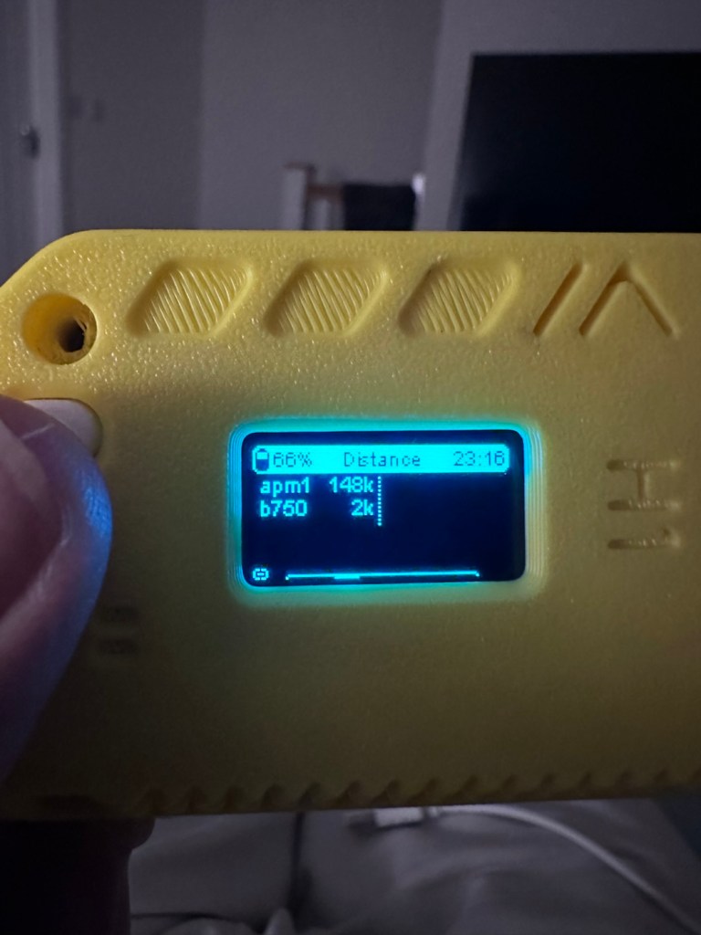
Here is where things become weird, and it’s the point that you realise that others are already stepping away from the true local message usage that was intended to try and make the system a longer range one incorporating the internet as a form of transportation for messages. This makes me scratch my head as surely the internet would be one of the first modes of communication to go down if there was some catastrophic event that took out traditional modes of communication? However, there is this mode that can be accessed called MQTT:

MQTT is a lightweight, publish–subscribe, machine-to-machine network protocol for message queueing/message queuing services. It is designed for connections with remote locations that have devices with resource constraints or limited network bandwidth, such as in the Internet of things (IoT). It must run over a transport protocol that provides ordered, lossless, bi-directional connections—typically, TCP/IP.[1] It is an open OASIS standard and an ISO recommendation (ISO/IEC 20922).

Wikipedia

Anyway, I had this setup, and I’ve now disabled it to ensure two things, that the system is true to its original intentions, and also to get a true idea of battery life using the most basic of setups.

Some things I have noted within the last two weeks are that if you are not in possession of a system with a GPS module, you then have to setup your node with a fixed location. This is absolutely no issue if your node is going to remain in a fixed position. However if you wish to take a node with you and move around, and let’s say you are 200 miles away from home, unless you go into your computer and reset the fixed location then you will always be 200 miles away from home but still showing as being “At home” hence giving false location information and giving anyone local to your new position false hope on them suddenly picking up a very strong signal over a long distance. Pretty much unheard of and impossible considering the power limitations of this system.

So one thing I will now do is attach the GPS module I mentioned towards the top of this post, to get accurate location information whilst mobile. There is a caveat here in that the power drain will be excessive for this battery and the GPS will greatly reduce its capacity.

Currently, with this node sitting in an upstairs bedroom window I am easily getting 24-36hrs from a single charge. Add to that a battery power bank I have with a solar charging capability I’m pretty much getting an almost endless period of usage. Weather has not been what I’d call particularly sunny recently, so I’d suspect capability would be much improved during summer months. I’ll just have to see how well this setup can work with the GPS system installed.

The current case I am using does not have room in it to facilitate the GPS board and antenna. For this purpose I have had to print a new case to house the unit in, and this is the barebones case pictured alongside the original case.
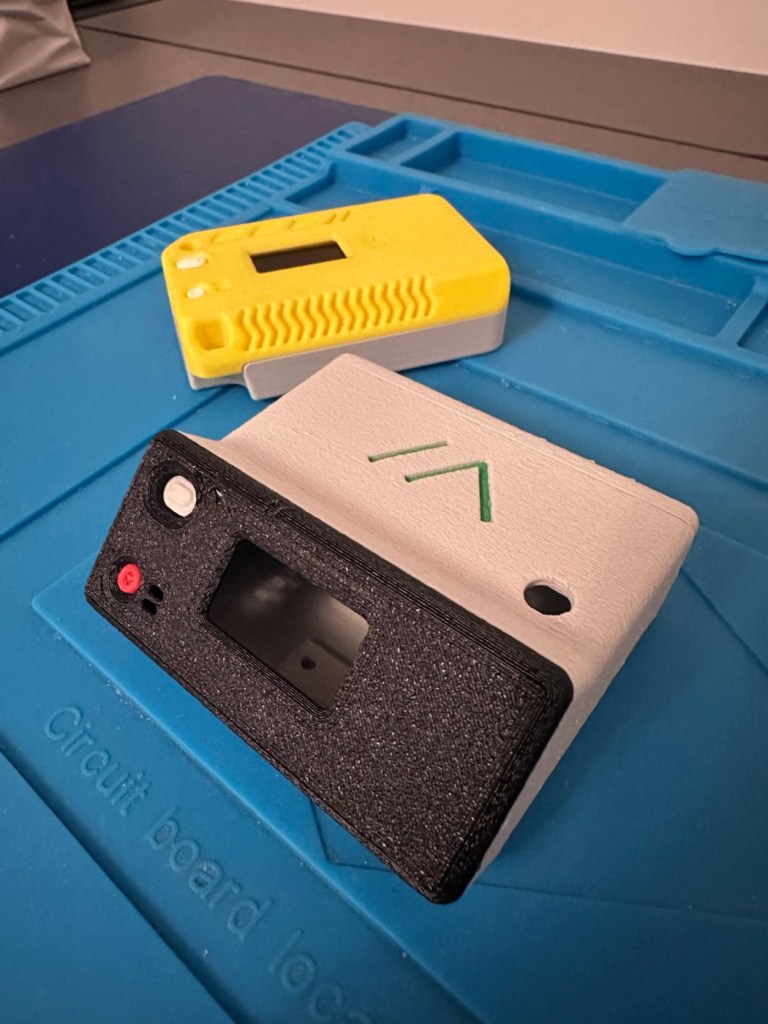
New case versus old

The old case will not be wasted. I intend to use that as a permanent fixed home base that I can use for testing the mobile one, and for building my own personal mesh system at home. The good thing with this system is that as well having public broadcast channels, you can also setup personal private channels for family and friends.

So let’s get the GPS setup.

The GPS board comes as a two part package. One part is the actual main board whilst the other part is the antenna on its own small board with a wire to attach it to the main board.
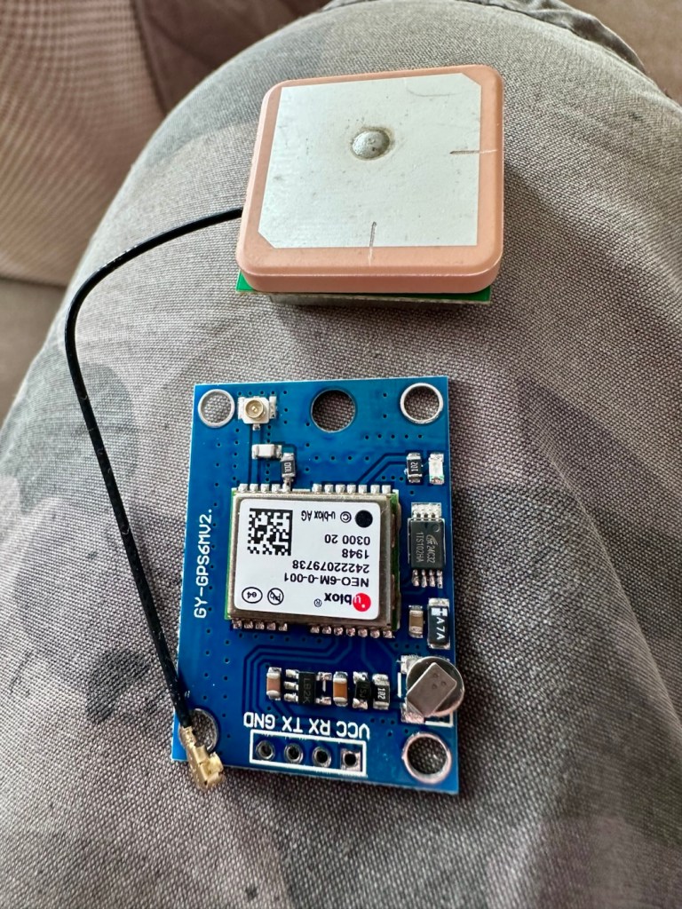
The GPS unit

Here is where the fun begins as we are going to have to do some soldering of this unit to the actual main “radio” board.

In a nutshell this little video explains exactly what you have to do.

Setting up GPS on the Heltec V3

I’ve had to solder 4 wires that connect the main board to the GPS unit. These are only temporary at this moment, as I need to be able to sit all components comfortably within the casing. I may have to add a switch, however I’m exploring other options at the moment. I’ll get to the reason why in a short while.
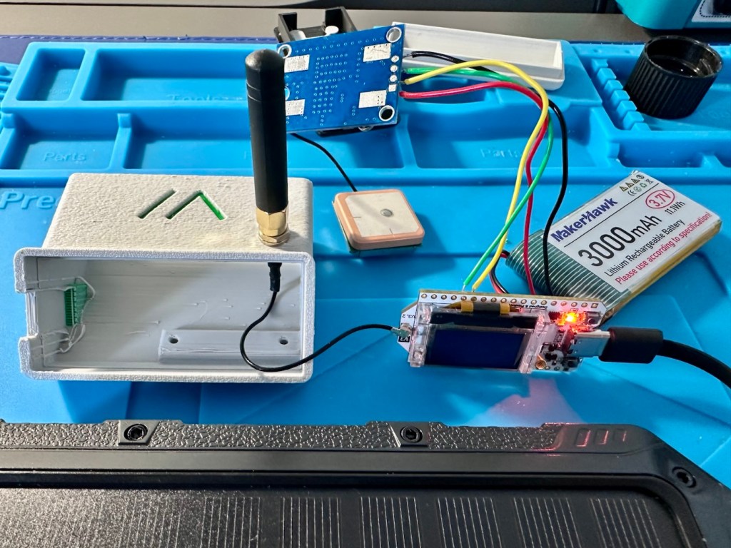
The case, the main board and now a GPS module added

The four wires connect power, a ground, a receive pin and a transmit pin, there may yet be a fifth wire, I’m exploring that option as stated above.
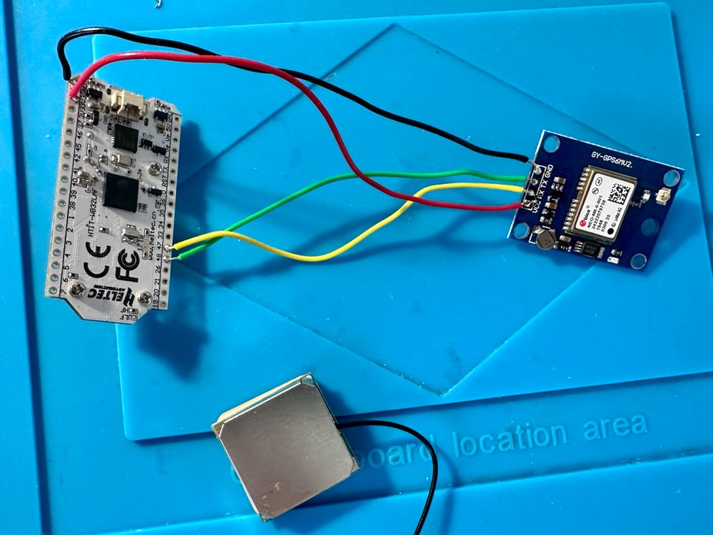
The temporary soldered wires

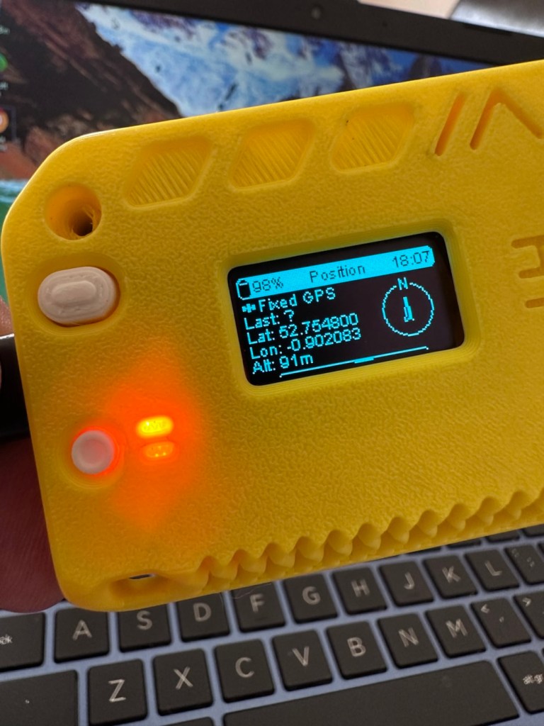
So does this work? I’ve charged the battery up to 100%, I’ve made some changes to the settings within the operating system and have turned the unit on. These system fires up and then a separate blue light on the GPS board flashes indicating that there is power to the GPS board.
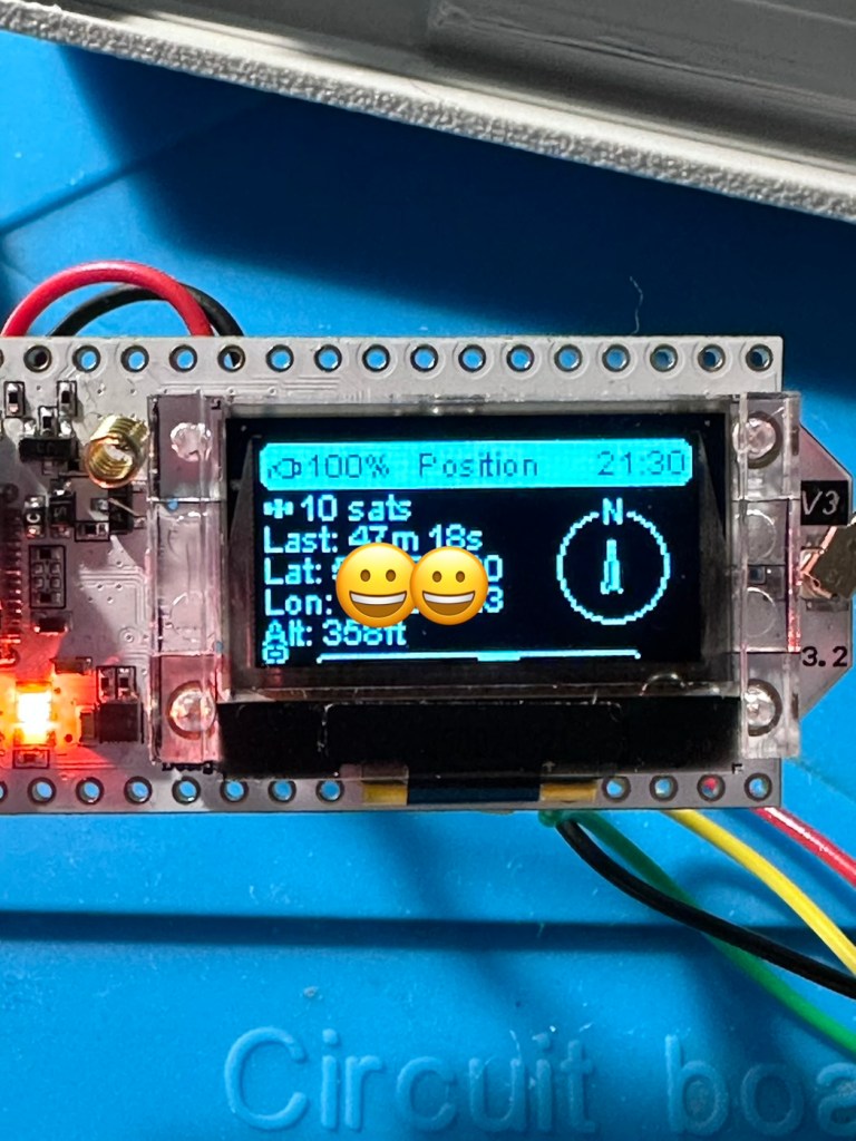
All working

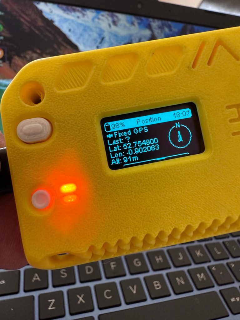
And then there is confirmation of 10 satellites being tracked, a height asl, and a longitude and latitude bearing, all seem to be working. But how accurate is the GPS reading? I put these readings into Google maps and the result is spot on. In the picture below the blue dot represents my phone location, and the red dot represents the GPS coordinates from the GPS module. Working perfectly👌. All smiley faces are just disguising the readings, much that I appreciate your reading of my shenanigans, I don’t have enough tea cups to welcome you all in 😂
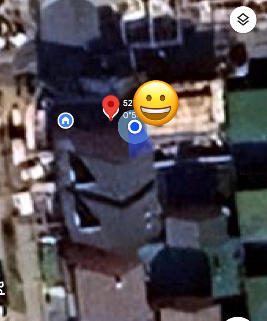
iPhone position and GPS module position

Previously prior to the addition of the GPS module I did state that I was easily getting 24-36hrs of life out of this battery on a single charge. That is going to change quite significantly as the GPS module is a super power hungry beast. I’ve currently set the GPS module to transmit its position once every hour. To be honest I could probably transmit once every 8-12 hours as i am currently in a fixed position and not moving. If I were in a car, I might even look at transmitting the coordinates every two minutes as this appears to be the default setting for a mobile node, and that would certainly drain the battery in no time. It would probably be best practice in this situation to have the unit running on power as the car is moving.

But I’m sticking with the hourly setting at present, just to do a basic drain test. This battery was on a 100% charge setting at 21:30hrs this evening as you can see in the photo above, I want to see if it will still have power 12hrs from now. No doubt power will deplete a lot quicker with the GPS module in place.

Depending on the results, this will help me decide if an extra wire or component or even both is needed within the circuit, and the reason for this is to be able to disable the GPS signal when not required. This modification in its simplest form can be as simple as putting a switch in the 3v supply wire, or by including a MOSFET (an electronic signal switch) into the circuit to allow the main board to automatically turn the GPS on and off via settings built into the software. I’ll make my decision when i see the results after I rise in the morning, and also depending on having the required components somewhere within my spares boxes.

About 7am the following morning (Approx 10hrs after setup) the power level is sitting at a comfortable 50%. The last GPS broadcast was at 02:37 in the e morning, I don’t know why this was as it’s set at a one hour cycle, I’m not complaining, maybe it didn’t have a successful signal to lock on to? Who knows. I have to take my wife out on an errand at about 07:30 so I’m going to put the GPS signal to a two minute cycle, put the bare bones set up on the parcel shelf of the car and just see if it works.
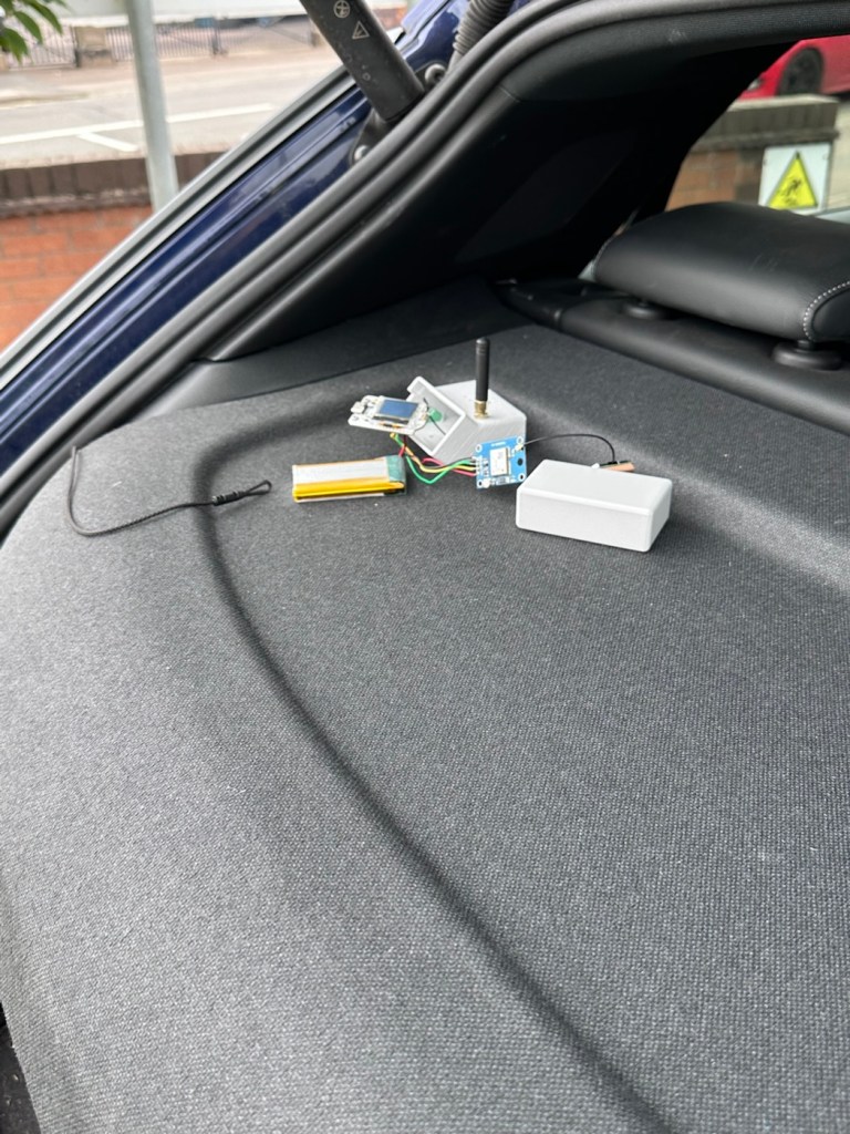
Barebones in the rear of the car

And it has worked perfectly.

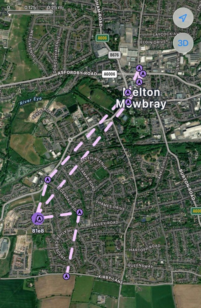
Log of the journey
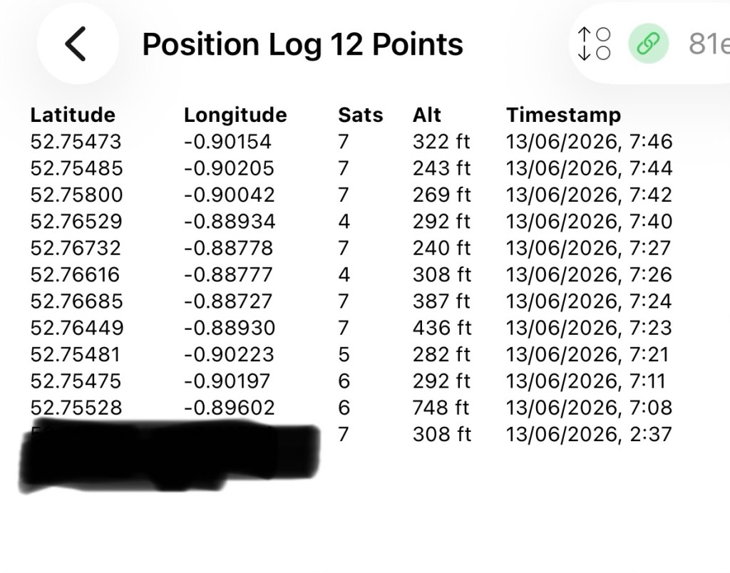
GPS log

In the GPS log above you can see how it has performed. The received data at 02:37 in the morning was the last on the hourly cycle, and then at 07:08 was the first of the two minute cycle prior to me switching it back onto a one hour cycle again at 07:46. I’m now going to leave it alone until we reach the 12hr mark and I’ll see how this small trial has gone during this period.

We’ve reached the 12hr post, and the power level is 45%. So over the 12 hr monitoring period with the GPS on a one hour cycle we have used 55% of the battery capacity.
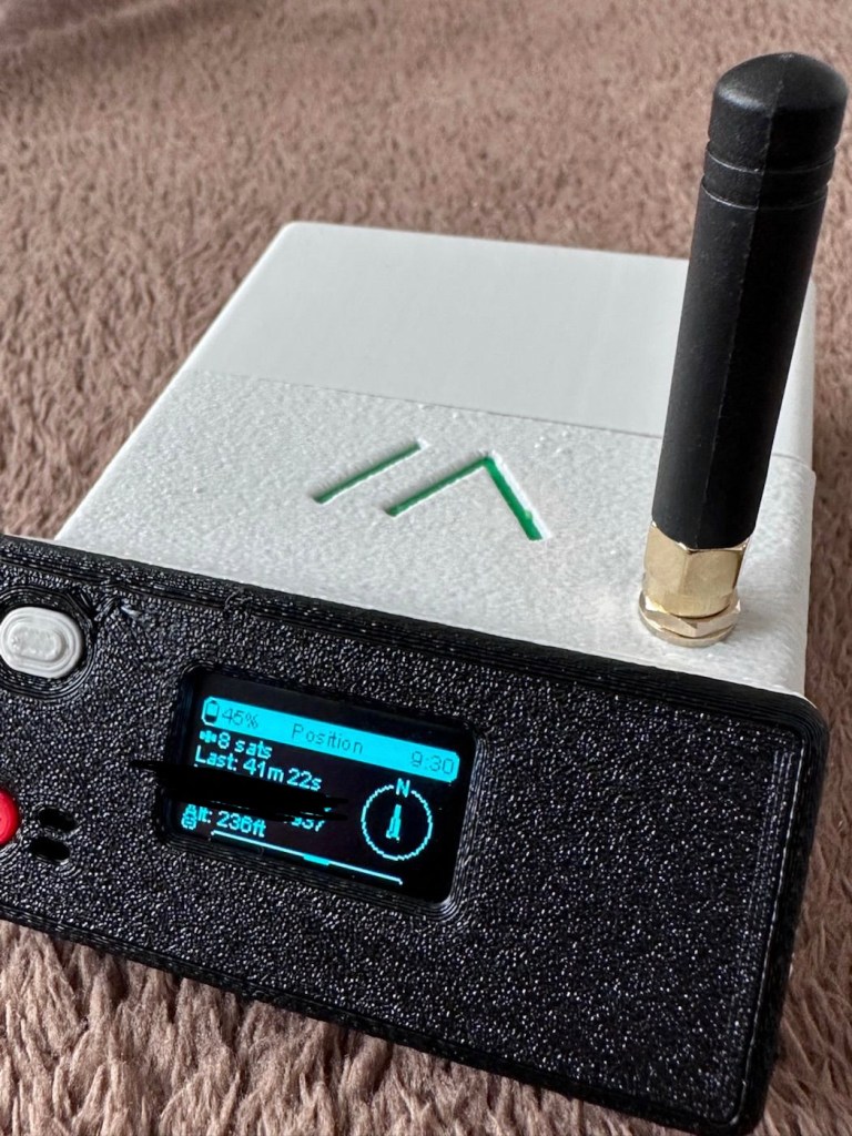
If you look at this log of the diagnostics over this period you will see a gradual decrease in battery capacity (Blue line) with the only noticeable disturbance being when I turned the GPS to a two minute cycle at 07:08 this morning when I had to take my wife out.
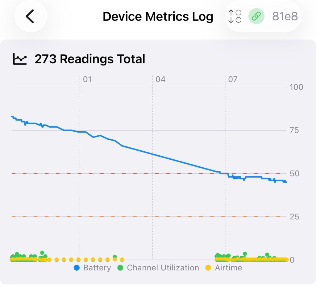
Device metrics over 12 hrs

Overall it’s a pleasing result but I’d suspect even with a low usage of the GPS module I’d probably only be able to get 18hrs of usage maximum from a single charge using the GPS on a one hourly cycle. Using the 2 min cycle I’d probably struggle to get 12 hrs of use from a charge, maybe even less, compared to the normal battery life of 24-36hrs without the GPS module you can see that the difference in power consumption that is involved. As I have said previously the GPS is quite a power hungry addition.

But do you know what? The figures are pretty good to be honest. If I use the unit at home I will reduce the GPS signal to probably one cycle every 3-6hrs. If I’m out mobile I very much doubt I will be driving more than a few hrs maximum, so I can always switch cycle rates as required.

So. Do I need to add another cable or that MOSFET discussed earlier? Probably not, it’s not essential but sometimes it may be advisable or recommended to maintain anonymity so a switching system would benefit in those situations.

For the meantime I’ve just thrown the bare bones unit into its case with no proper spacing, as I’m going to take the unit out again today on a slightly longer journey for a family gathering. It will be good to see how it performs and to see if we can get any noticeable contacts in an area other than my home location. You never know that Meshtastic may have a greater following or uptake in that area.
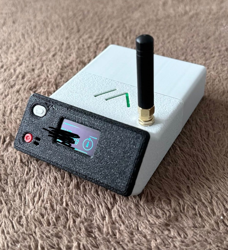
And the journey out to the family gathering registered just fine. I’m confident and happy that the GPS addition has been successful.
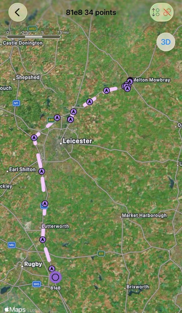
The route to the family gathering

And guess what. There are even fewer nodes in use to make contact with here. I am, or appear to be the only one, it’s a lonely pastime at the moment.

The journey back home was fine and again the GPS worked as it should. Now to get the GPS power management installed, I’ve decided to go with the “N” type MOSFET option, I’ll get this installed, tidy up the wiring and get the case placement sorted. I’ll then just reflash the software to remove any glitches and then I will rename this node as my mobile option – (MeltonFoxMob – MEFM). I’m then going to get myself a second node to build and install, probably a solar node, that will become my permanent home installation node.

I’ve just purchased a couple of N type AO3400a Mosfets as I don’t have any in my spares box. Putting this in circuit will allow me a greater control of the power consumption via the units firmware.

It’s been tested over approximately 6 weeks now and to be quite honest, I’m not that impressed. There has been one single contact over that period, however the vehicle tracking option is ok (ish) there are some questions about the system turning itself off about half way in to a longish journey, but that could be down to me not having the MOSFET in place.

I personally think it’s a fad thing until it really takes off. I will keep my mobile unit and possibly a home unit in place to see just what happens. There is only one node working in my immediate area and I’m not even sure if that is monitored in any way.

These kind of systems have to start somewhere and they just need a few more people to pop on board and spread the word. If I turn mine off then it’s another potential possibility for the advancement of the technology that will have disappeared. I’m going to be persistent with it for the foreseeable future and hope others come on board. But at the moment I’m not overly impressed. Things can only get better as they say.

Thanks for passing by. It’s always most appreciated.
Still Haunting

Yep, the Ghost radio service I reported on in August 2025 is still operating in the East Midlands and beyond

Back in August of 2025 I wrote of a radio station I had stumbled across on the DAB network. Ghost radio service.

It’s probably the post that has had the most views on my site, strange! And has been mentioned in numerous chat rooms and sites across the t’internet,

Because no one really knows what the hell it is or who owns it.

Here’s a few definite facts.

  • It can only be heard in the East Midlands, especially around the city of Leicester.
  • It has been heard out in suburban areas on the far outskirts of the city.
  • It is someone making ghostly groans and moans.
  • It is only on DAB networks.
  • No one appears to admit ownership
  • There is very little information on line.
  • 7 months after first being heard it is still active.

And it’s still active today. Here’s a video taken a couple of days back.

Spooky 👻

Digging around, checking the OFCOM site amongst many others, the only new information I can find is listed below:

Key Details About Ghost Service:

  • Content: The station broadcasts a continuous loop of a “ghost” moaning.
  • Origin: It is an avant-garde art project created by a multiplex owner to challenge conventional ideas about broadcast radio and demonstrate the efficiency of their MP2 encoder at low bit rates.
  • Platforms: Initially spotted on DAB (Leicester SSDAB on block 9B and Lubra SSDAB on block 8A), it has also been heard on FM (87.9 MHz) in areas like Billingham and Middlesbrough, sometimes switching to Christmas music.
  • Other Projects: The same entity operates another station on the same multiplexes called “Catalytic Converter,” which plays cat sounds.
  • Visibility: It has garnered attention from local listeners and YouTube creators such as Fox’s Den. 

And it mentions me. How quaint!

Thanks for passing by, have a great day. Thank you 🙏

At last, the new work space takes shape.

The workspace is starting to take shape. Normal service to resume soon. Maybe I can catch up with this backlog now.

I’d pretty much closed down my workspace, when we sold our old house back in August last year. Everything I used the most was pretty much moved into storage as we prepared to make the move to our new home. All I was left with was a few screwdrivers, so needless to say, content on this site dwindled, whilst purchasing continued, hence I currently have 29 posts, in draft, awaiting completion as I don’t have a suitable workspace or the equipment available at the moment to complete any of them. I even purchased a 3D printer in November of last year for my birthday, it has been in storage all this time, I have now brought it home and have now made my first 3D print, that post can be found here: My First 3D print attempt

Things are about to change.

We pretty much have every room in the house now up and running. We are settled now and the final boxes have been attended to within the house, and we are finally getting to the point where regular recycling visits to the tip to get rid of the old cardboard boxes are finally coming to an end.

The next stage in my wife’s own words are, “ we can now get Dave’s room sorted.” The words I’d been waiting for.

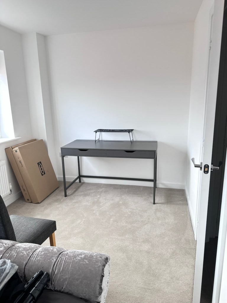
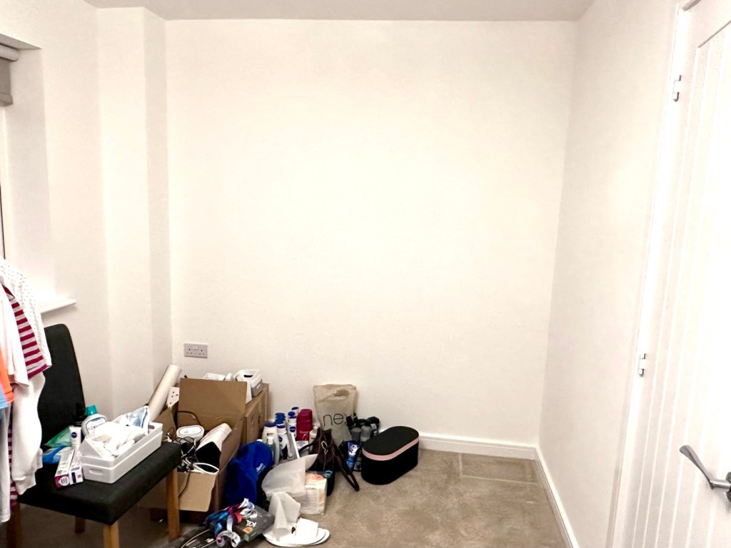
My workspace – a wall in a guest bedroom

I’m calling it my room but in theory it’s not a whole room. It’s part of the third bedroom where I am probably just occupying one wall at the end of a guest bedroom, it’s all I need, I have a Garage to do all the blokey stuff in, this space is purely to work upon all my cameras and other more delicate items of work.

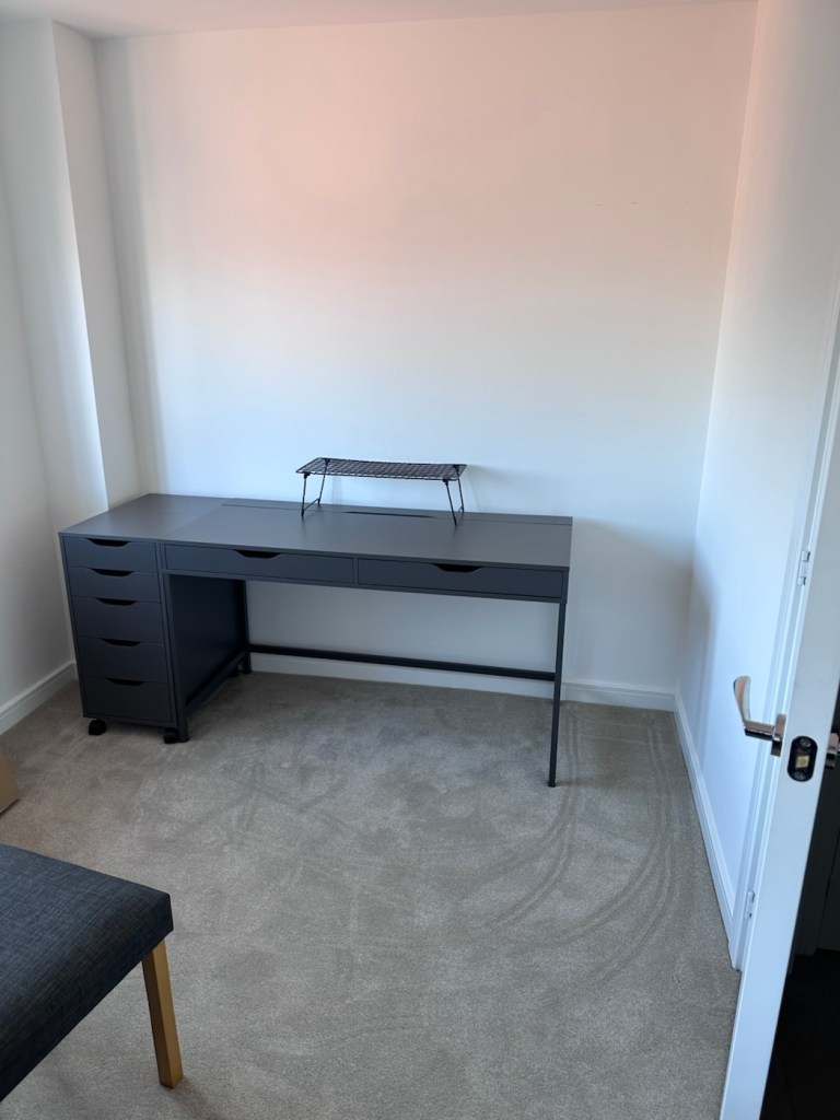
Whilst visiting a certain Scandinavian furniture store i have purchased a basic setup for me to begin working on. The good thing about these furniture systems is that you can start with a basic layout and just expand upon it, and that’s the plan.

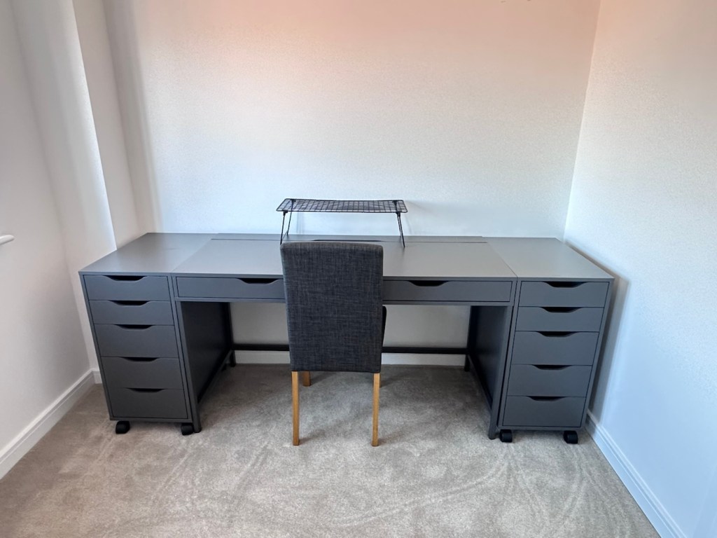
I have a desk and drawer system arriving today, and quite a bit of construction to do, once this is in place then I can start getting my gear from storage and get it back into place. It will be nice to have all my equipment in a permanent placement, without having to take it all apart and storing everything back in boxes after I have used it. I’m looking forward to this as to be honest, I’ve really missed it. However I have been pre occupied around the house and there has been an awful lot to keep me busy, there’s been no rest really, I must be very wicked 😂

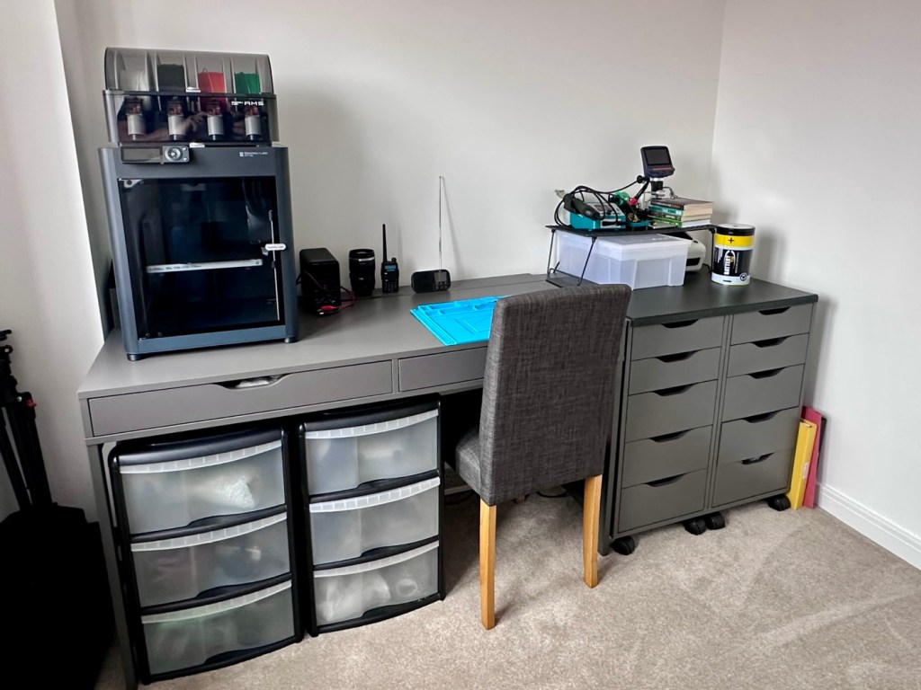
So as of 10th March, I’m quite pleased to say that my workspace is now ready to use. It’s still a way from being complete as I still have stock to bring from storage along with the last few tools and boxes of components. There are still shelves and storage to put in place, but at long last I can now sit down and finally start to play catch up with my ever expanding backlog.

The workspace….liable to be moved about yet again

I must admit I’ve moved things about, and I’m probably liable to move things about again over the coming days and weeks, even months as I can’t quite decide how the setup should look. It’s probably going to be a few sessions of me not being able to find tools, parts and cameras that will help me decide just what, should be where. In the meantime, it’s good that a kind of normality has been restored, and I can now start to resume where I left off all those months ago.

Meshtastic

Ever heard of the Meshtastic decentralised off grid communication network? You have now. Dive in and get involved.

What’s that? I hear you say. Well, I’ve been trawling t’internet recently and one of the chaps I follow on YouTube, Gabe, has got me very interested in this particular mode of radio communication. Here’s a video of him explaining Mesh communications in his own charming and extremely enthusiastic way.

Meshtastic – as Gabe sees it

The good thing about Mesh networks are that no licence is required for use, this means the system is truly open to everyone. As a registered radio amateur this system is of interest to me in the spirit of experimentation, and that’s what’s good about this particular mode. Everyone can do it at a very reasonable cost. In the UK it’s been present for a few years now and has an active core of participants. However, usage is very patchy and still developing, and due to the short range and lack of other users to repeat messages, its general take up is going to take a while yet, or in usual fashion it may even be a mode that just dies out due to lack of involvement. It’s not a mass-market tool yet, but a growing niche interest, especially among amateur radio, DIY tech, and preparedness communities. However, that said, in areas with little or no cell phone coverage this could well be a lifesaver. Below is a little bit about Meshtastic.

What is Meshatastic?

Meshtastic is a free, open-source project that lets you create your own decentralized, off-grid communication network using LoRa (Long Range) low power radios. It’s designed to let people send short messages and share data without relying on mobile networks, Wi-Fi, or the Internet.

Open-source & community-driven: Anyone can contribute, modify the software, or build devices with the firmware.

LoRa technology: Uses low-power, long-range radio waves in unlicensed frequency bands (like 868 MHz in the UK/EU).

Mesh networking: Devices form a mesh by rebroadcasting messages. Each device acts as a node that can relay messages to extend coverage.

Meshtastic’s goal is to provide reliable communications when other infrastructure is absent or unreliable and to offer a flexible platform for hobbyists and practical users alike.

How it works

Networking: LoRa radios transmit small data packets over long distances with very low power. Each device forwards messages it receives to nearby devices, forming a mesh network that extends reach beyond single-hop radio range. The network is decentralized — no central tower or internet access is needed.

User interaction: Devices can connect to your smartphone via Bluetooth and use the Meshtastic app to send messages or view locations. Messaging is typically text-based (no voice or high-bandwidth data).

Why use it?

People adopt Meshtastic for many reasons, often tied to availability, resilience, and independence from traditional networks:

Outdoor activities: Hiking, camping, biking: Stay in touch where cell signals are weak or absent. Location sharing: Useful for groups and safety.

Emergency situations: Natural disaster backup, communications can continue even if cellular networks fail. Communities and some groups experiment with using Meshtastic as an alternative communication layer during outages.

Technology and DIY: Education and hobbyists use it to learn about radio, mesh networking, and embedded systems. Integrations with IoT sensors and other projects are possible.

Community and social projects: Enthusiasts set up community networks, share nodes, and even run local meetup groups. 

What do you need to get started?

Basically, Amazon, EBay, and the Chinese suppliers such as Ali express have all you need. Needless to say the Chinese options are far less expensive if you are willing to await delivery. Just type “Meshtastic kit” into your browser to view your options.

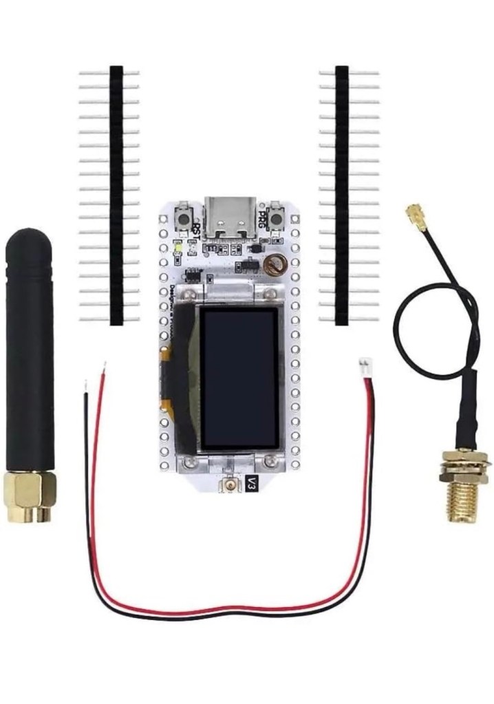
As I’m in the Uk I can give some prices for the most basic setups within my country. To be honest, all that is needed is a Meshtastic main board of which there are a few to choose from, a power source and a mobile phone to do the setup. Something like this below.

From Amazon in the uk I can get this board, for £18:99GBP and that’s all I need to get started.

Amazon uk

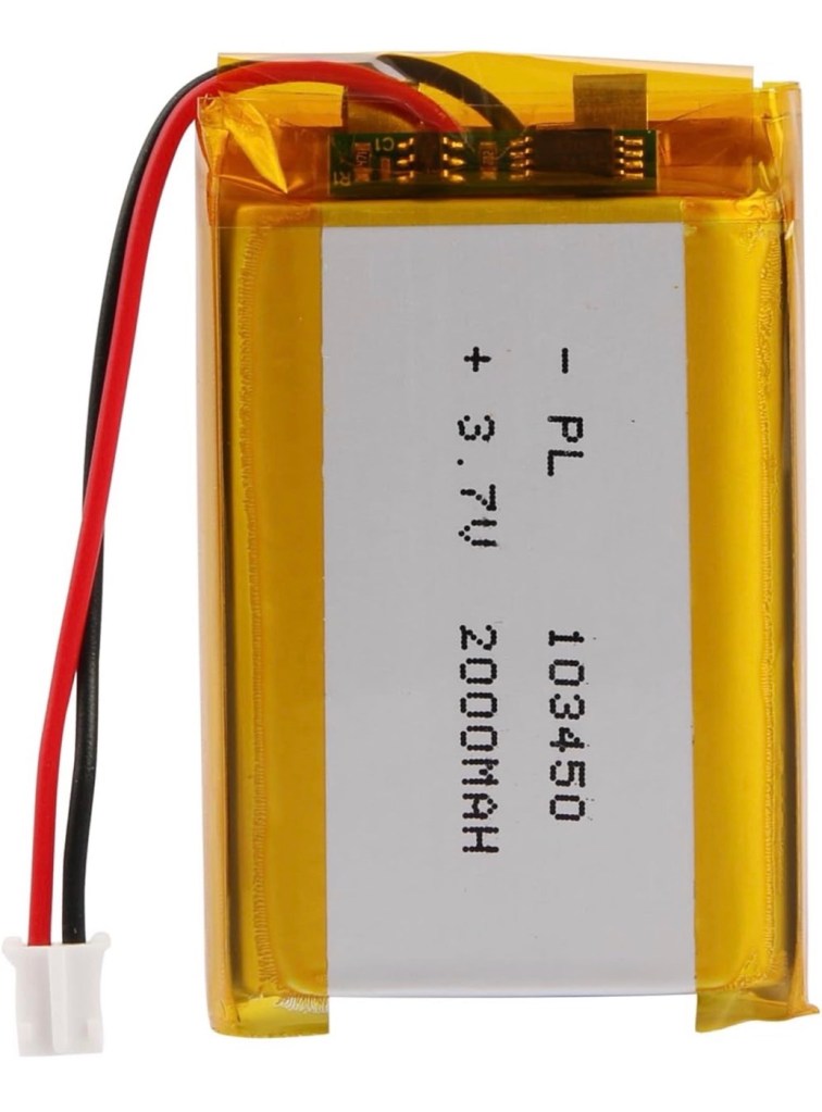
Add to that a small battery and you can probably power this unit for between 24hrs or even a week, dependant obviously on the battery capacity and how you have the system set up. A battery in the uk on Amazon would cost around £6-£10 GBP. You can buy enclosures to make the unit “pretty” or you can even 3D print your own. I think I will print mine when I finally have my printer up and working.

A suitable battery

On the Chinese platforms these items can be purchased at a greatly reduced price, the main board can be purchased for around £3:00GBP, you can even purchase two entire units for less than the one that you get from Amazon. It really pays to shop around.

I’m shortly going to dive into setting up a Meshtastic node, I’m even going to set up an APRS one under my radio licence conditions, but that will be another post.

So hopefully this post may introduce others to an off grid communication mode that may well assist those in remote areas or with extremely limited cell phone coverage. As soon as I’m ready to build and place my node I will write a post regarding its build, programming and eventual usage. It is all very simple technology and worth having a read about on the Meshtastic website : Meshtastic introduction

Text you soon!

Ghost radio service

No, I’m not talking about secret Russian radio stations, that seems to be all the information you can find, regarding ghost stations on the internet. This Ghost service station has popped up on DAB radio in the Uk, in Leicester, and there is no info that I can find about it online, and all that it seems to be broadcasting is someone making spooky ghost sounds. Have a look at this little video I made of it, only about 30 seconds long.

Spooky

I’m wondering if someone is having a laugh on this channel, maybe it’s on hold, just awaiting a new residency, who knows? I believe this is based somewhere in Leicester city as I’m unable to tune it, anywhere outside of the city limits. I’m surprised that our radio regulators at OFCOM are allowing it, however radio standards aren’t what they used to be nowadays.

Strange one isn’t it?

Have a lovely day all.

R.E.M 30 years ago today

My first R.E.M concert

Yes. 30 years ago today on the 30th July 1995 I was at Milton Keynes Bowl in Buckinghamshire Uk with one of my buddies. We had taken the train from Watford on a lovely sunny day to watch what was our new favourite band at the time, never knowing that very soon they would occupy a place in my heart as my favourite band of all time. And 30 yrs later my wife will attest to me randomly putting on the music, only to tell me to turn that noise down, she really is a heathen 😂

We were fortunate that day to have three superb support bands who would go on to carve their own little parts of music history The Cranberries, Sleeper and Radiohead.

Back in the early days of the bowl they had a strange system in place where they didn’t accept money to purchase beer, you had this weird system where you had to go and purchase “tokens” before the gates opened, to use as your currency within the stadium. If you didn’t purchase enough or any tokens at all, then it was tough – you would be having a dry old day. I remember purchasing plenty, I was paying the price for days after – no pity for me it was all self imposed.

Here’s the set list for the day. It was also broadcast live on the BBC’s Radio one.

Set list

It was a cracking day out and a day that would stick with me throughout my life, as I became a fan that would now follow them,whenever they came back to the Uk. The last time I saw them was in Hyde Park London just after the London bombings, on 16th July 2005.

Man I really miss them. I’ve always said if they were to reform just for one concert anywhere in the world, then I would be there. The wife has always been on standby should that date ever be announced.

But I doubt it ever will, but we can only live in a constant state of hope. We all need that bit of hope in our lives.

In the meantime, I’ll just go and crank that stereo up to eleven, just so I can hear the wife shout at me one more time 😂.

Have a lovely day.

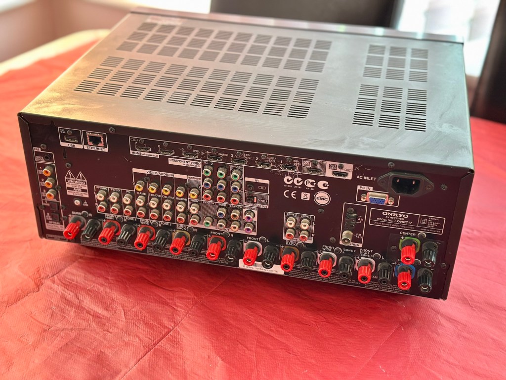
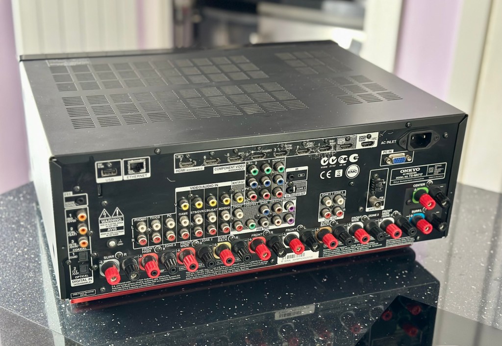
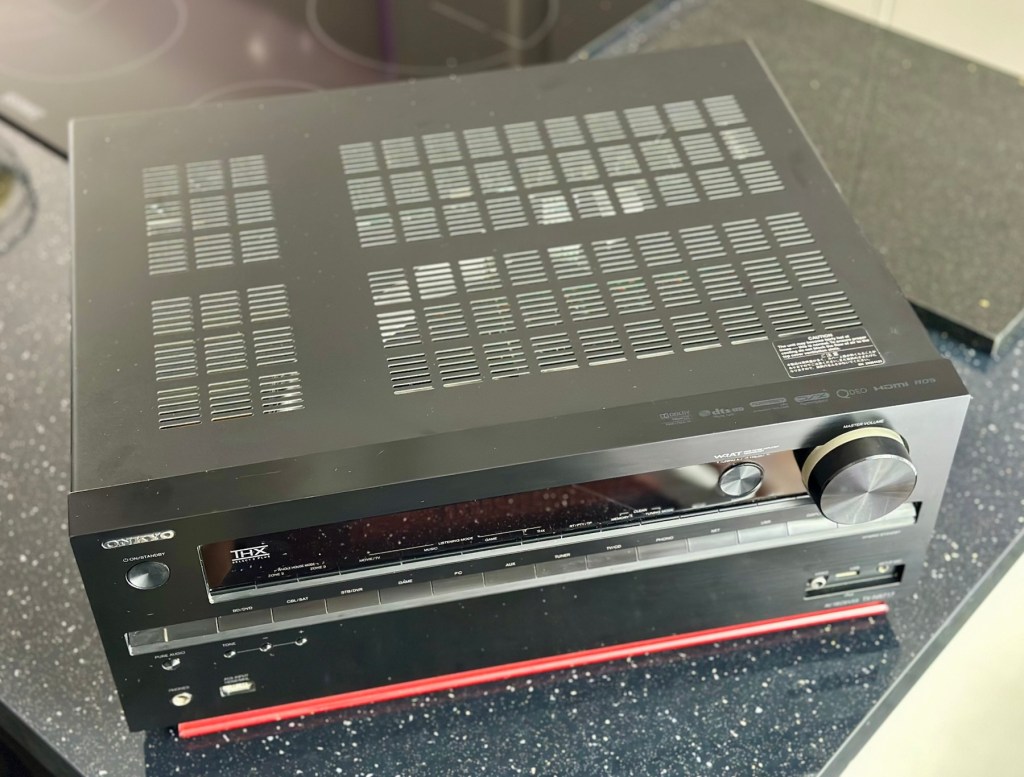
Onkyo TX-NR717

7.2-channel home theatre receiver, Internet-ready

Onkyo TX-NR717

A bit of a different one here, i get into work one day earlier this week, to be told that one of my colleagues in a different area (Nottingham) will be calling with something to discuss. That call occurred today and the discussion was about his home theatre surround sound system that had packed up on him, and would I be willing to look at it for him to see if I could manage a repair. Though it’s something I don’t usually do repairs on, I said why not? I need to look into other areas of repair and as long as it wasn’t urgent and there was no urgency, then I’d certainly look into it for him. It turns out there is no hurry and he will get the item down to me in the next few days.

So I now have a task, that I am really quite excited about. And for obvious reasons I want to do a good job.

Here’s a little bit about this item

With the power to fill large rooms with THX certified sound, this cutting-edge receiver is ready to integrate and distribute entertainment throughout your home. More than a home cinema processor, the TX-NR717 allows you to access music on PC, stream from MP3 tunes, explore online radio, or connect your iPod/iPhone to one of two USB ports. You can distribute any of these various stereo sources to other rooms for house-wide entertainment. With a total of 10 HDMI connections, this receiver converges HD content from all your components – even your smart phone media via a front side MHL/HDMI – and provides easy input selection with InstaPrevue technology. HDMI also enables intuitive GUI with overlaid quick set-up menu. Video upscaling to 4K, Audyssey DSX seven-channel sound expansion, and Audyssey 2EQ room correction are all included. Sound quality is quite simply the best in class, with powerful WRAT amplifier, three-stage inverted Darlington circuitry, and discrete output stage components delivering an otherworldly entertainment experience.

Onkyo TX-NR717 – AV network receiver – 7.2 channel – black

Release date: April 2012

Onkyo

I’m looking forward to this project, a little out of my comfort zone, but it’s the best way to learn about how these things work. And I need some exposure to these types of systems and the issues that can occur within them.

Assessment:

This unit has just about reached its teenage years, and if this can’t be repaired then the owner will be looking at his alternatives. However replacement units have also grown in both features and price now, so if this current box of tricks can be given an extended lease of life then everyone is a winner, and one less item gets to go to landfill.

I have downloaded both the instruction manual and the service manual, so I am equipped with a full list of components as well as the official schematic diagrams of the circuitry layout. I’m suitably prepared for this one.

The report from my work colleague is that it was working fine up until a week ago when it would just not switch on. He has replaced the two quick blow fuses that he saw when he opened the unit, however the issue still remains. He hears clicking when he turns the system on, this could be an issue in the standby circuit, however I will have to wait to have the unit in my possession to investigate this any further.

Straight to the point…just how I like it

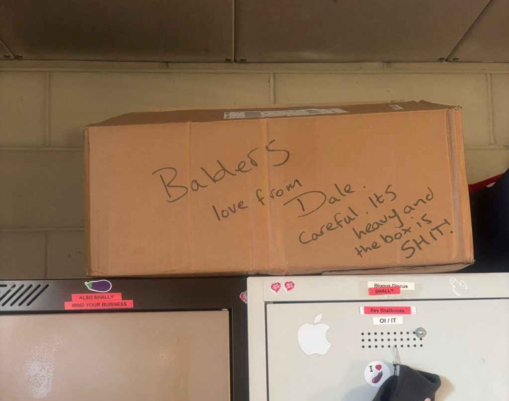
Just got a message from one of my colleagues at work to say the parcel from Nottingham has been collected. Just love the straight to the point way these guys inform me of any safety issues and concerns they may have 😂

More surprises

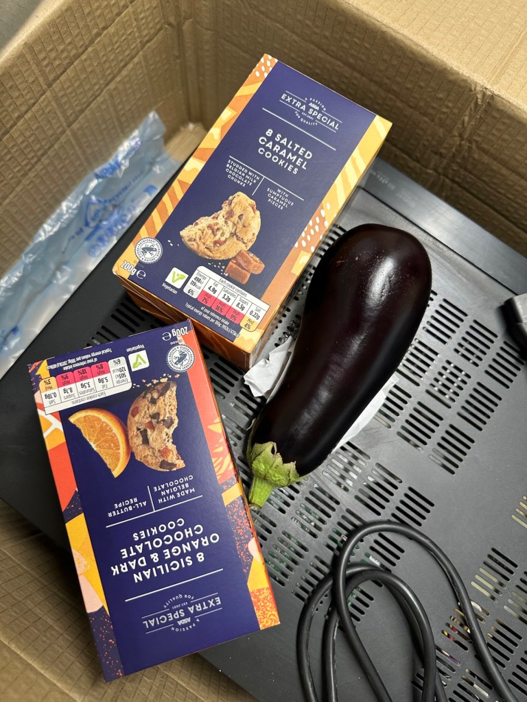
And on opening the box, more surprises. Biscuits, they are my downfall, and don’t ask about the Aubergine, we won’t go there, that’s a private joke 🤦‍♂️

Right, serious head on now and I’ve plugged the unit into the mains and without touching anything at all, all I can hear is a metronomic clicking that appears to be emanating from the power board circuit area. This will be my first port of call.

Repair:

There are two well known issues regarding these units and I am going to look at both of these before getting in any deeper. The first issue is around the relay and its associated 150 Ohm resistor on the main power board, the second issue is around a defective capacitor on the standby board, and eliminating one issue will either highlight, or clear the other. If both issues are addressed with no change to operation, I will have to look in to the issue a little deeper.

Issue one relates to a problem with the relay on the main power board. Most people don’t realise this but pressing the power button on an Onkyo receiver does NOT turn off the power.  The power button merely sends a signal to the MAIN CPU telling it to close a relay (to turn the system on) or open a relay (to turn it off).  When you press the power button on an Onkyo and nothing happens (no clicks, no brief lighting up of the front panel) the root cause is often a blown coil in the main power relay. 

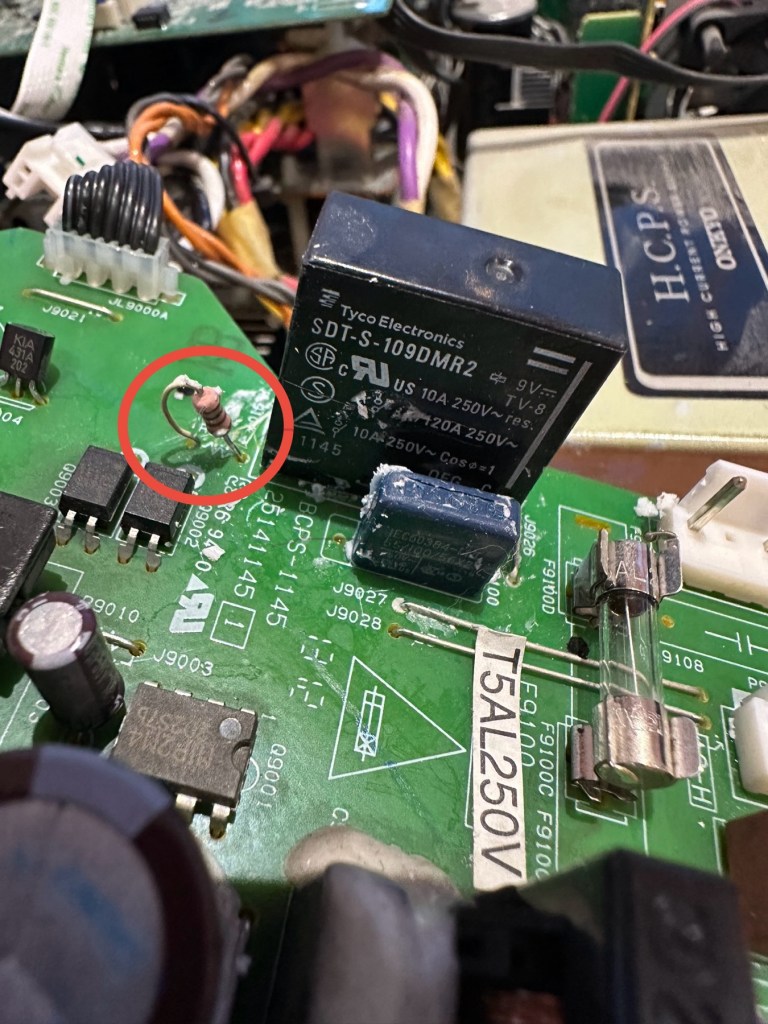
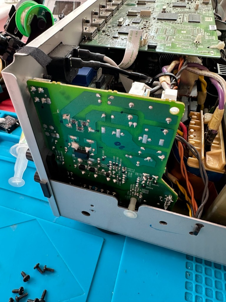
Main relay is the item under the thick coating of white silicone at the top of the picture

Beside the relay to the left is a resistor that should be reading 150 Ohms. This particular one is reading 144 Ohms so is reading a bit lower than expected. This could be sufficiently low enough to allow the relay to fail. So at this point this looks like a possible point of failure. Either way they need to be replaced before we can advance any further.

Silicone removed. The faulty resistor is within the red circle

I need to obtain these parts, the relay will need to be shipped from China, and I need to check my resistor stock to see if I have a suitable replacement resistor. The relay also should have a similar resistance to the resistor beside it, the healthy range for the relay is between 80-200 Ohms.

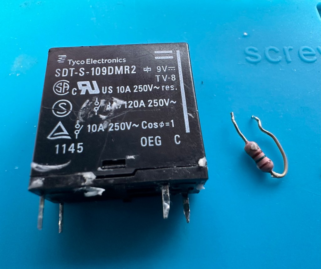
I have removed both components from the board to test them out of circuit.

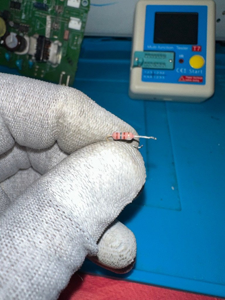
The resistor beside the 9v relay is a 150 Ohm rated resistor. This one reads at 144 Ohms and is to the lower end of the rating of +/- 5%, it would probably suffice, but i’m going to replace this one just in case. The only other resistor in this circuit is a 47 Ohm resistor and that reads exactly as it is rated, so there is no issue there. I believe the bone of contention here is that the relay is 9v sitting upon a 12v power rail. This is probably the reason issues have occurred with these units in the past, and looking at a number of forum posts, it is quite acceptable, even recommended to use the higher voltage 12V versions. I’m sticking to the original design on this repair though, I can only presume the 150 Ohm resistor placed just before the relay has something to contribute in controlling the operation of this relay. Maybe that’s a design fault within this model, I just don’t know!

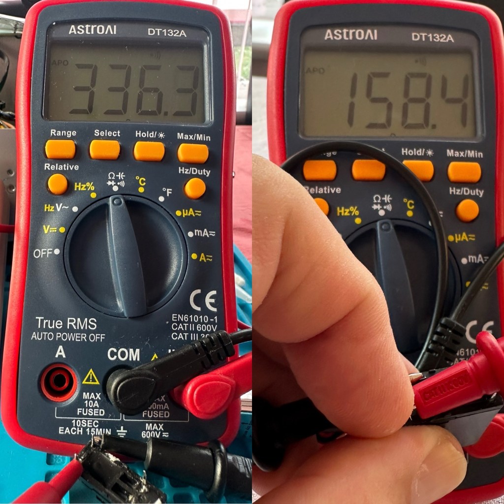
I have tested the relay using a multimeter and a 9v battery. I have used the battery to short across the power poles where I can hear the relay clicking, but when the relay is on there is no continuity across the other two pins when there should be, this isn’t happening so I suspect this relay is stuck in the open position. The Ohms rating across the pins shows 336 Ohms, so i am lead to believe this could be a problem with the coil inside it, as it shouldn’t really be that high. I understand from what I have read, that a rating between 80-200 Ohms is classed as acceptable, and outside this range could indicate that there is an issue. I’ll just have to wait until the new relay arrives and carry out some tests to see the comparison between the old and the new relays.

336 Ohms is that an issue?

I’ve dismantled the cover from the relay to get a look at the coil. In the little video below you will see the coil switching, however you will also see the contacts meeting but there is no continuity. The contacts have a coating of contamination on them probably from age or arcing, it looks like a carbon deposit, as when they adjoin there is no contact made, no flow or continuity, unless you put light pressure on the contact and then you get the continuity. It is at fault, it shouldn’t be doing this. A clean of the contacts might breathe some life into it, however give it a couple of months and you’d probably have to remove it again, and the contamination isn’t the only issue, don’t forget the relay reading that appears too high. A new relay costs less than £4:50GBP delivered from the other side of the world, so I might just as well go for a new relay. It makes sense.

Inside that failed relay

I’m not going to venture any deeper into this unit yet, not until these components arrive and I can get them back into place. I want to move through this fix confidently and slowly, have a better understanding of what is going on and not leave myself confused with bits and pieces everywhere, clueless to what is occurring. I wouldn’t achieve anything by working like that. Knowledge is king here and I’m here to learn. And I do now have the schematics available to follow.

I’ll have to wait about 2 weeks for the relay to arrive so I’ll just have to put this repair to one side and on hold until then.

Ok the new relay has arrived and the first test I did on it was to take an Ohms reading of the coil side. Now if you have paid attention, you will have seen that the old relay was reading 336 Ohms when it should be somewhere between 80-200 ohms. This new relay is reading 158 Ohms and I feel a lot better about that, it falls right in between the expected spec.

Old relay reading on the left versus new relay on the right

And if you want to see the relay actually working and displaying continuity then have a browse at this video below, the polar opposite to the first video I posted above 👆

The new relay with good continuity

The resistors I ordered have now come through and have been tested, I have a couple of candidates displaying better test results, so we can now look at getting these two components back in place to see what occurs.

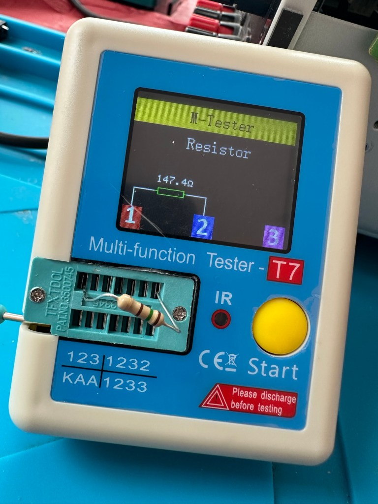
I’ve put in place a new resistor, slightly higher value than the previous one coming in at 147.4 Ohms. It falls within the 5% tolerance so should be fine.

147.4 Ohms

The relay has been soldered back in place, really simple just four points to solder and we can now reassemble the power board back into the chassis.

I’ve taken the unit into the garden at my wife’s request, as I have to use some high pressure air to give it a good blast to get rid of some dust and furballs. This has worked well and quite a dust cloud was witnessed across the garden, it’s fair to say it’s a lot cleaner inside than it was.

I’ve now put the case back on and the unit is now sealed from prying eyes and inquisitive fingers. I’ve given the entire case a good polish and I must admit it is looking nice and shiny and very presentable. I just have to hope and pray that it turns on. I see no reason as to why it shouldn’t but you just never know. You can always fix one problem only to be chasing it around the system as it develops into another fault, repairs can sometimes go like that.

Let’s plug it in and see what happens 🤞

Result:

I’ve plugged it in and turned the power on. No bang, only silence, just a single click when the power went on, this is good. When the power is turned off you hear the standby relay do the same, all is as it should be.

The standby relay has clicked in when turned on at the power socket, and is not repeating that metronomic sound that was there originally. Superb. Now to turn the power button on, on the front panel.

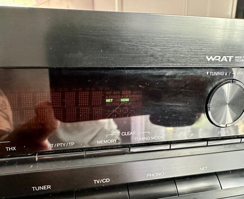
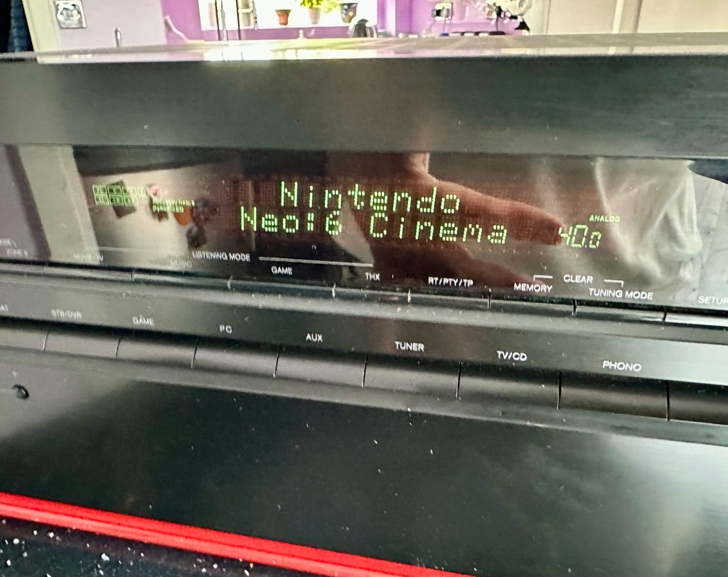
We have a display. Excellent it is working.

All buttons are operational, I don’t have the surround sound speakers as they are at the owners house in Nottingham, i also don’t have the remote here that also allows me to do other tasks, however that is not important as the unit is now operational and displaying what it should, and once it goes back into his media wall with all his speakers and other related sound and Av equipment, i am confident beyond doubt that it will be operating just as it did prior to this issue developing.

I will be handing it back with the advice that should the issue occur again we look at updating the relays with new 12v versions to replace the current 9v ones. But I doubt the problem will re occur, and this repair should see out the next few years at least and by then this unit will probably be sold, or passed on to someone else when he decides to upgrade his system.

Below is the little video I sent my colleague showing him the unit now working

It’s now working

But for now, it works. I am pleased as punch with this repair as I have stepped out of my normal comfort zone here. I have been extra vigilant, studied many a schematic diagram and learned a lot from this project. I didn’t rush ahead of myself and took this repair one little bit at a time, testing all along the way and addressing each issue in the order that it has arisen. And I’m damned happy with that.

It’s been a learning project for me, and I’m glad I’ve undertaken it. Life is for learning, and I’m living that life.

Many thanks for passing by, as you well know it is always very much appreciated.

Edit:

Today the 29th July I have had a message back from my colleague to say that he now has the unit back in his media wall. And I’m pleased to say it’s working perfectly. He’s very pleased and so am I.

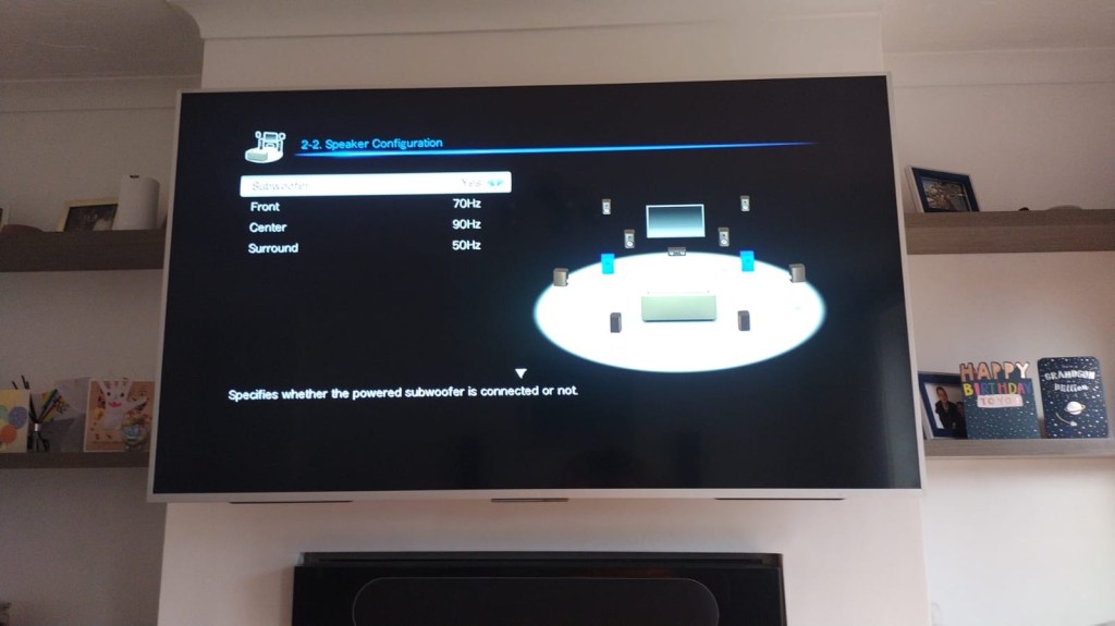
Back in place and working fine

He’s pestering me to bill him, but I’ve told him that I’m only taking one currency and that’s not money or crypto. No, my method of payment will be in Biscuits. I told you I’m a Cookie Monster and this entire repair only cost just £4:17GBP. That’s not a lot of Cookies, but it’s credit in the bank if these guys need any further repairs carrying out. Word of mouth, works wonders.

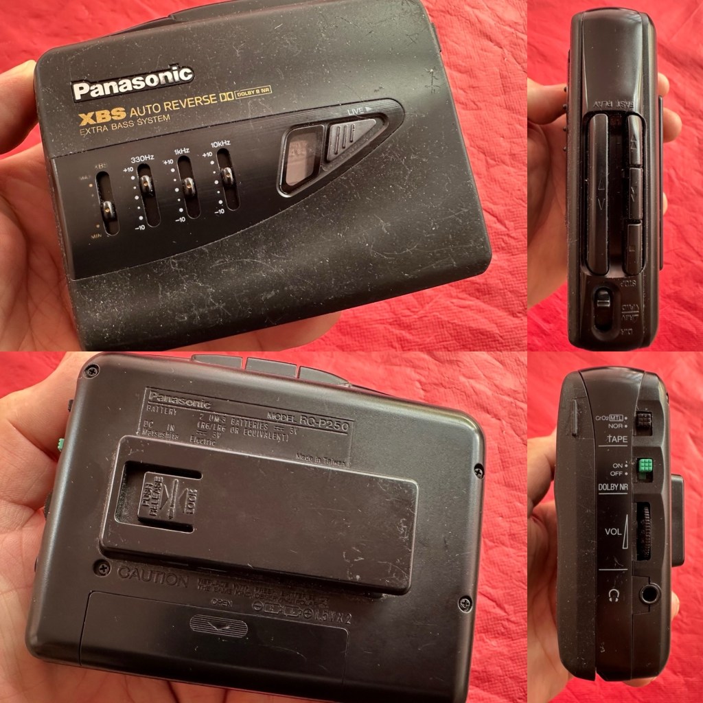
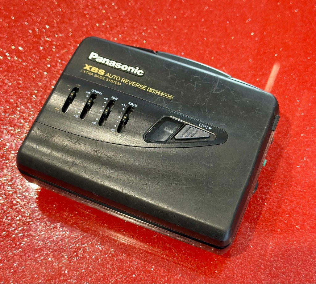
Panasonic Walkman cassette player RQ-P250

At a family gathering this weekend, an elderly family member approached me and asked if I could take a look at his Panasonic personal tape player, and maybe get it back up and working.

Who am I, to turn down such an invitation, so I took it on and promised him I’d have a look into it. There is, “No rush“ I was told. Just as well, as it’s busy in every aspect of my life at the moment.

Here’s the spec:

Type: Auto Reverse Cassette Player

Tape Type: type I, CrO2, Metal

Output: 20mW

Battery: 2 x AA

Power Supply: RP-AC33 (3V DC)

Dimensions: 114.2 x 84.4 x 33.1mm

Weight: 156g

Finish: black

Year: 1993

Hifiengine

Panasonic RQ-P250

Assessment:

It’s well used, and has always been and if I can get it working, will continue to be so. At the grand old age of 79 my brother in law is not about to change his ways and is quite comfortable listening to his old Cassette collection whilst out and about, on trains quite a bit of the time, as he travels up and down the country. He’s a lovely old fashioned set in his ways guy and we wouldn’t have him any other way. It would be blooming lovely to get this back to him working again.

It’s scarred, been well used but looked after, apparently it’s gone from playing quite well, to slowing down and dying completely. I think I know what the issue is but I’m not going to curse myself by saying I know what is wrong, when it actually turns out to be something totally different.

On the Beach – Chris Rea

And I love his choice of music. Let’s get this repair underway so we can listen to Mr. Rea in a lovely crisp sounding manner befitting of an 80s rock star.

Repair:

Batteries in place, earphones connected, push play. No movement from the capstans, and even when put in forward and reverse there is no movement from either capstan. I can hear all the electrical noises such as the tape head picking, and I suspect at the grand old age of 32 years old that the drive belts have probably given in. Let’s open it up and have a look.

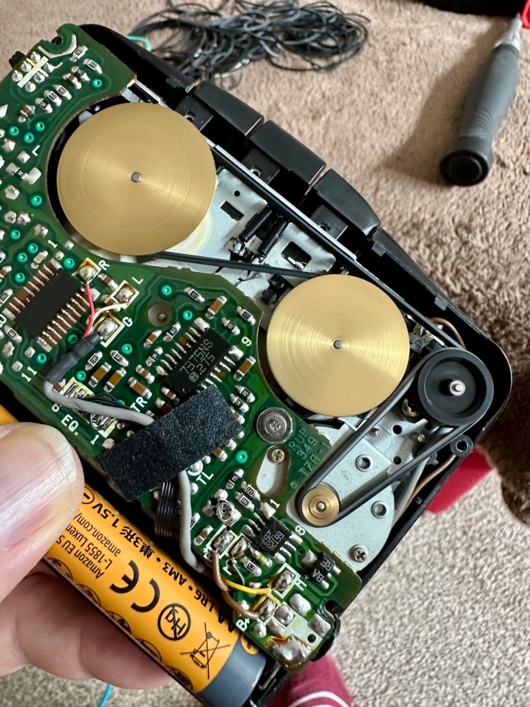
And just as I thought. Two drive belts in here, they are both loose, one though is so loose that it has wrapped itself around the two capstans, no wonder it wouldn’t start up.

I have plenty of these belts spare, I just had to sort out the two closest matching in size. Too slack and you introduce warble, too tight and it will be off speed, you need to get it just right. Adjustments can be made to the motor speed but this will only come back to bite you once the belts wear in.

I’ve put two new belts in place, and at some frequencies there is a little wobble, but with Dolby switched in place this can be removed digitally, this will settle over the coming weeks after more use.

I have used some silicon grease on the cogs, I have put contact spray in the motor and the volume controls, and used IPA to clean all the tape contacts and capstan wheels and posts, it’s basically been given a little service to see it forward for a while longer.

Body now reassembled, new batteries put in place, it’s time to test it.

Result:

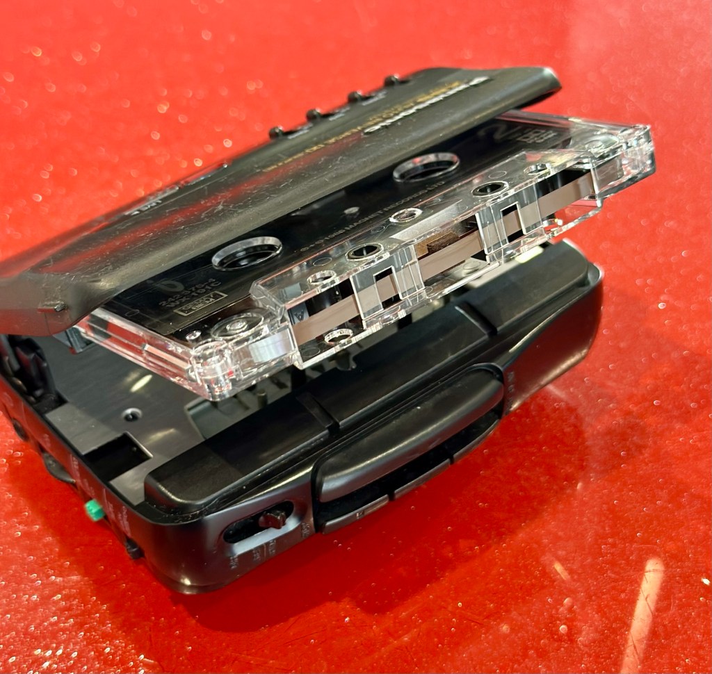
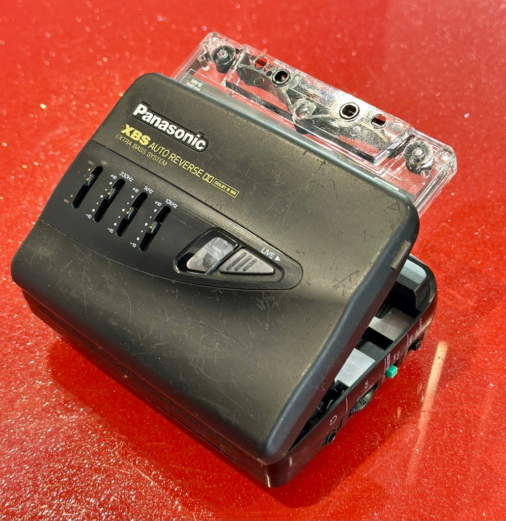
A quick polish, to tidy up, won’t get rid of the deep scuffs, just makes it a little more presentable. Cassette inserted, headphones plugged in and as expected it’s working just fine, we can hear Mr.Rea in all his gravel voiced glory. So can you, in this video snippet below, that hopefully won’t get a copyright strike 🤞

🎶 On the beach 🎵

So there we have it. Another item brought back to life with about 30 minutes work. It’s going to make someone’s day, and I’m as pleased as punch that I could play a part in contributing to that.

There you go. Hope you enjoyed this quick fix.

Many thanks for passing by. Always most appreciated.

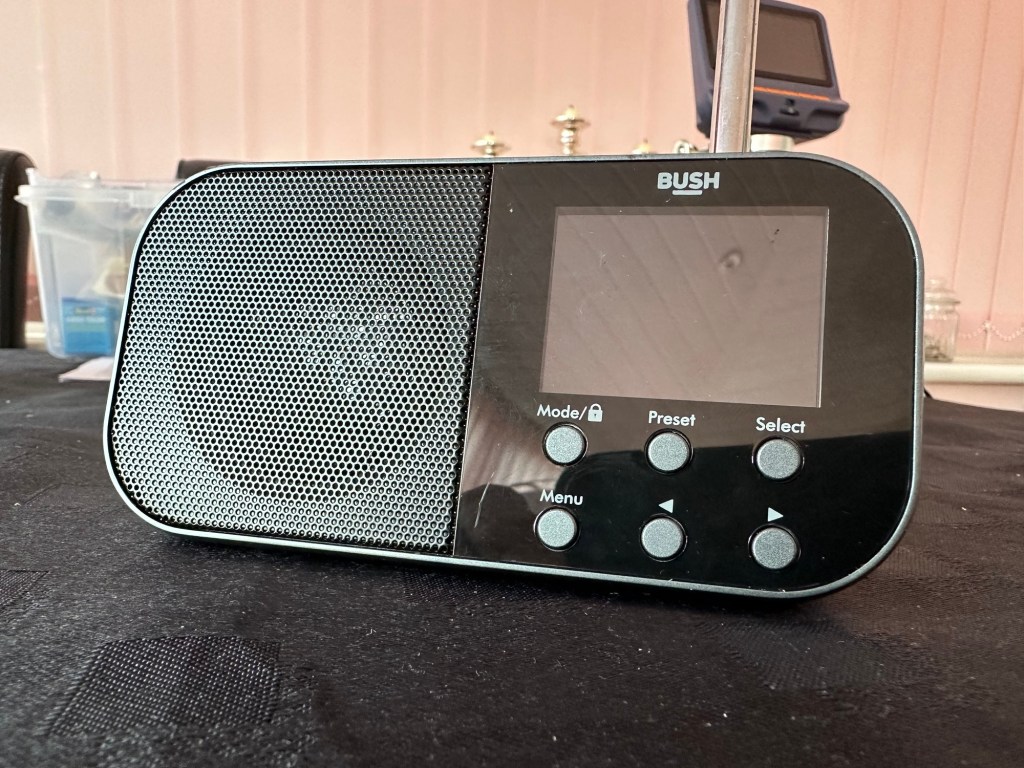
Bush handheld radio

Here’s what the posting stated:

Grading: FAULTY (USB SOCKET)

EBay

Simple as that. And yes it’s a tiny radio but in excellent condition cosmetically.

Bush handheld

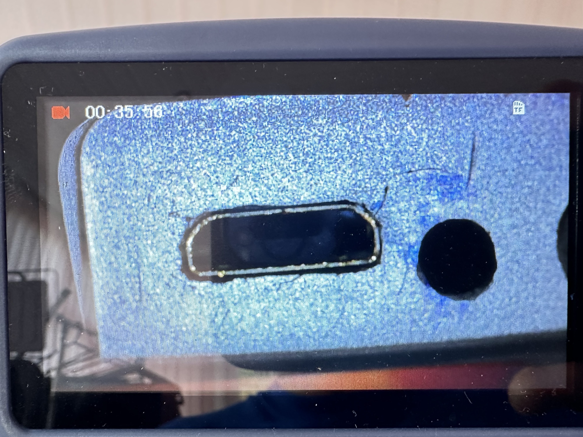
On inspection it’s obvious that the micro USB port is damaged and will need replacing.

I’ve ordered some replacements USB ports from our friends in China so I’ll have to wait a few weeks before I can progress this project any further.

Micro usb ports

The ports have arrived from China, so let’s look to see if we can repair this unit.

*This project has been on the back burner since May 2024. 13 months later and I’m now on it*

Hello all, time to clear that backlog and what better place to start than here. I do in fact have two of these with the same problem so this is a two for the price of one project.

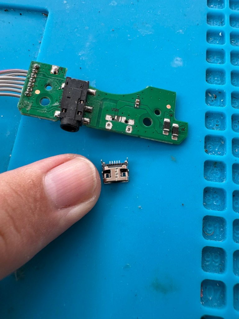
This should be a simple case of replacing the faulty charging ports that are both micro usb ports. They are small believe me.

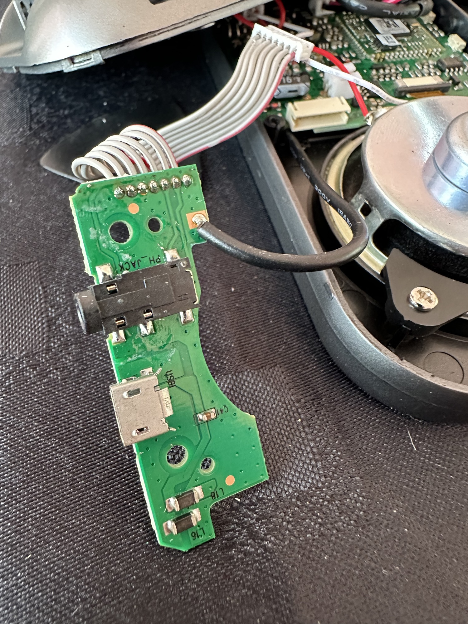
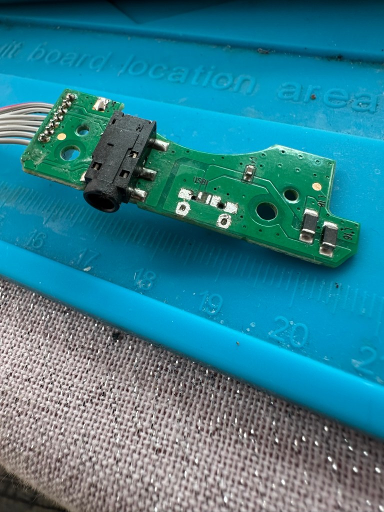
There has to be some preparation before we can get the new port on. Using a soldering iron and flux and a little solder wick, I clean the old board remove the old solder and give a good clean with IPA. I then prime the small connections on the rear of the charge port with a little solder. Now I put the port to the board and tack on the earth points. Then using a rework hot air gun I blast the port at about 350 degrees Celsius and hold the port in place with some tweezers until I see the solder glisten and melt around the port. I take the heat off and let the solder set before moving the tweezers and when it’s cooled a bit I check that it’s setting straight, all connections are good and solid. I then just add a tiny bit more solder to the anchor points for strength.

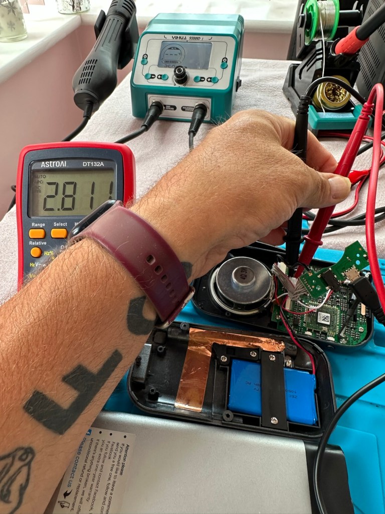
Whilst this is cooling down I check the status of the battery. It is a 3.7v rated battery and is currently holding a charge of 2.8v. It’s a little low but far from being dead. The second battery shows a similar charge.

Battery level

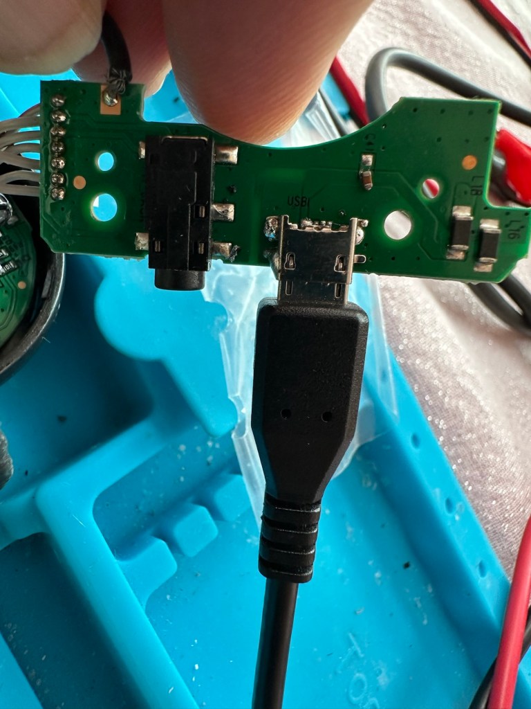
After the solder work has cooled I use my battery pack connected to a small ammeter to see if the radio and more importantly the battery is demanding any power.

Well that’s good news, 5v in and the demand from the battery is 0.96 of an amp. The battery is charging. And the fix is as simple as that.

Two perfectly good radios

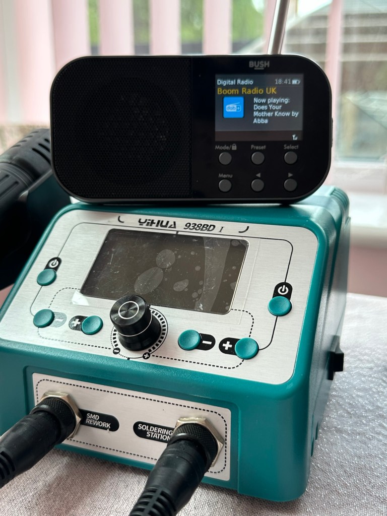
A little bit of soldering aerial contacts and a couple of other wires back into place and the whole unit clicks back together. Two screws inserted in the rear and time to switch on. Both radios tune in perfectly and the sound is surprisingly good for these little units. I’m keeping one in my work space at home, as I love having some music around me, I’d sooner listen to the radio any day as I hardly watch TV. The other radio will go into my work locker for when I’m working nights or in the workshop.

In my work space, but it won’t be staying here…

Im very happy with this little project, it only took about an hour and I don’t know why I left it so long. Another couple of items saved from the tip, it amazes me that these units probably all suffered with the same problem of inferior parts that failed early on in the radios existence. Kind of scares me just how many did go to landfill.

Two cracking little radios

Well at least these two are going to carry on for a few more years yet. And that’s a positive in my eyes.

Thanks for passing by. 👍

PT109 wooden torpedo boat kit – Maiden voyage

This article is the third and final instalment of the build of this beginner’s kit that can be found here: PT109 wooden torpedo boat kit – construction and here: PT109 wooden torpedo boat kit – finishing

Today 16th June 2025 and this boat that I was gifted for my last Birthday back in Nov 2024, finally underwent proper trials on water, and thankfully after all the issues experienced during the building process it came through them with flying colours. There are a few little tweaks to do as a result of the maiden voyage, but this will only go towards making it a far better and less stressful task on future excursions. Boy was i nervy about today, what with all my family watching.

A nervous owner placing his boat on the lake…
And off we go…slowly

I only have the one battery for the boat so time was limited, and I probably managed about 15 minutes with it nutting about, before it stopped and had to be rescued by my Brother in laws boat that just happens to be a tug, a seaborne version of the RAC.

Luckily the seaborne version of the RAC were on hand

Anyway prior to that minor mishap the boat performed quite well, the motor is hellishly powerful and I thought it would go either of two ways. Either it would launch itself out of the water like a missile or it would go nose first into a deep dive towards the bottom of the lake. Luckily it did neither, however I did learn that turning at speed is liable to capsize the boat, so care needed to be taken when performing turns under power.

And she works…..

As usual I have learned a lot. It needs some minor tweaks such as a better centralisation of the radio gear in the hull, it needs some Baffles to be put in around the front deck where the hull and the superstructure join, to prevent water ingress at speed. The front does sit low in the water but at speed the contours on the hull do create lift, and this does work very well, so I am particularly happy with this.
A great day out, at the start of the holiday, and the fact I didn’t have to go wading to rescue a failed boat is also an added bonus. Really looking forward to showing the videos and pictures to the elderly friend who purchased this fantastic gift for me. They will be as pleased as punch, as they know about all the hard work and care that has gone into getting this project finished.

Thanks for following the journey with this project. As always it is very much appreciated.