

What is it?
I could go into lengthy detail but I won’t bore you just yet. Below I have quoted the Wikipedia entry that explains things in a nutshell better than I ever could. I will however give a few details of attempts I have made and equipment I use for carrying out this mode of communication. I am currently building a new radio for this mode that I will cover in a later post.

WSPR (pronounced “whisper”) is an acronym for Weak Signal Propagation Reporter. It is a protocol, implemented in a computer program, used for weak-signalradio communication between amateur radio operators. The protocol was designed, and a program written initially, by Joe Taylor, K1JT. The software code is now open source and is developed by a small team. The program is designed for sending and receiving low-power transmissions to test propagation paths on the MF and HF bands. WSPR implements a protocol designed for probing potential propagation paths with low-power transmissions. Transmissions carry a station’s callsign, Maidenhead grid locator, and transmitter power in dBm. The program can decode signals with a signal-to-noise ratio as low as −28 dB in a 2500 Hz bandwidth. Stations with internet access can automatically upload their reception reports to a central database called WSPRnet, which includes a mapping facility.
Wikipedia
What fascinates me most about this mode of communication is that in recent weeks it has gained a new audience as a result of a television documentary. This documentary was regarding the search for the missing Malaysian airways flight MH370 that vanished from radar screens on the 8th March 2014. An investigator tracking its disappearance has been cross referencing WSPR signals in the area that the aircraft was last reported and he has apparently plotted the route taken by monitoring these signals as they were reflected or distorted by the aircraft’s footprint in this area, well beyond the planned flight path.

My setup for testing propagation on a number of different bands is very portable as that’s normally the way I work when taking to the airwaves. I’m always moving around or working from different locations so it’s always good to be able to monitor conditions using a compact setup.
I do also have an aerial system set up in my loft that cannot be seen, it’s kind of clandestine in that way it does not grab the unwanted attention of my neighbours. I specialise in low power communications and again this does not draw the attention of anyone living near by as disturbance and interference rarely occurs. The maximum power level I normally use is 10 watts, but more likely somewhere around the 5w QRP level. My WSPR setup operates between 200mW and 5mW of power. Extremely low power, there is probably more power in that sports watch sitting on your wrist than what I am transmitting.
My Portable setup
I have an inflatable aerial, yep that’s right inflatable! Perfect for mobile operation using QRP low power technology, It covers most of the high band frequencies and I mainly use it on the 20 Mtr band (14mhz) or the 40mtr band (7mhz) though other bands are also available. Fully inflated it stands about 6ft high and can be hung outside, inside or just perched in a corner somewhere.

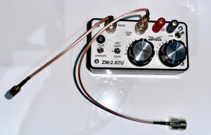
There is an antenna tuner , this is one I purchased from the States in a kit form and built myself. It’s called an Emtech ZM-2 Atu details can be found HERE
The actual transmitter sits in a small package not much bigger than a box of matches. This was purchased already built and is called a WSPRLITE classic. I am in the process of building a new transmitter and receiver combo that is also in a kit form, I don’t anticipate completing it any time soon as I just don’t have the time at the moment.

I have made a number of filters for the different bands (40mtr, 60mtr,80mtr and 160mtr) and these boards connect to the output of the transmitter to aid in obtaining a clean signal and to prevent deviation from the set frequency.

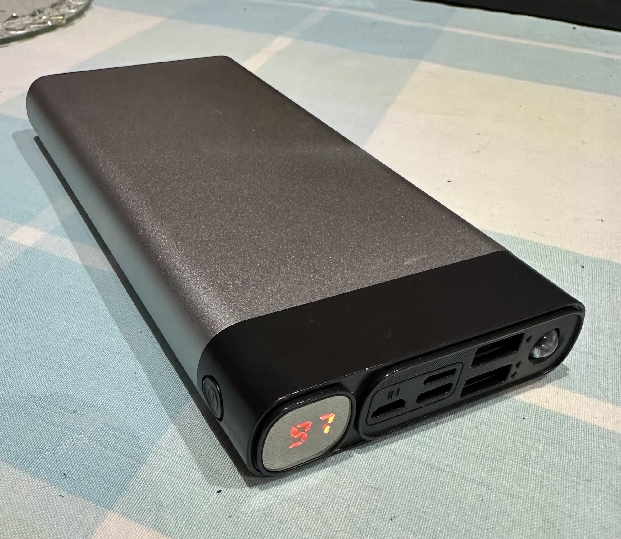
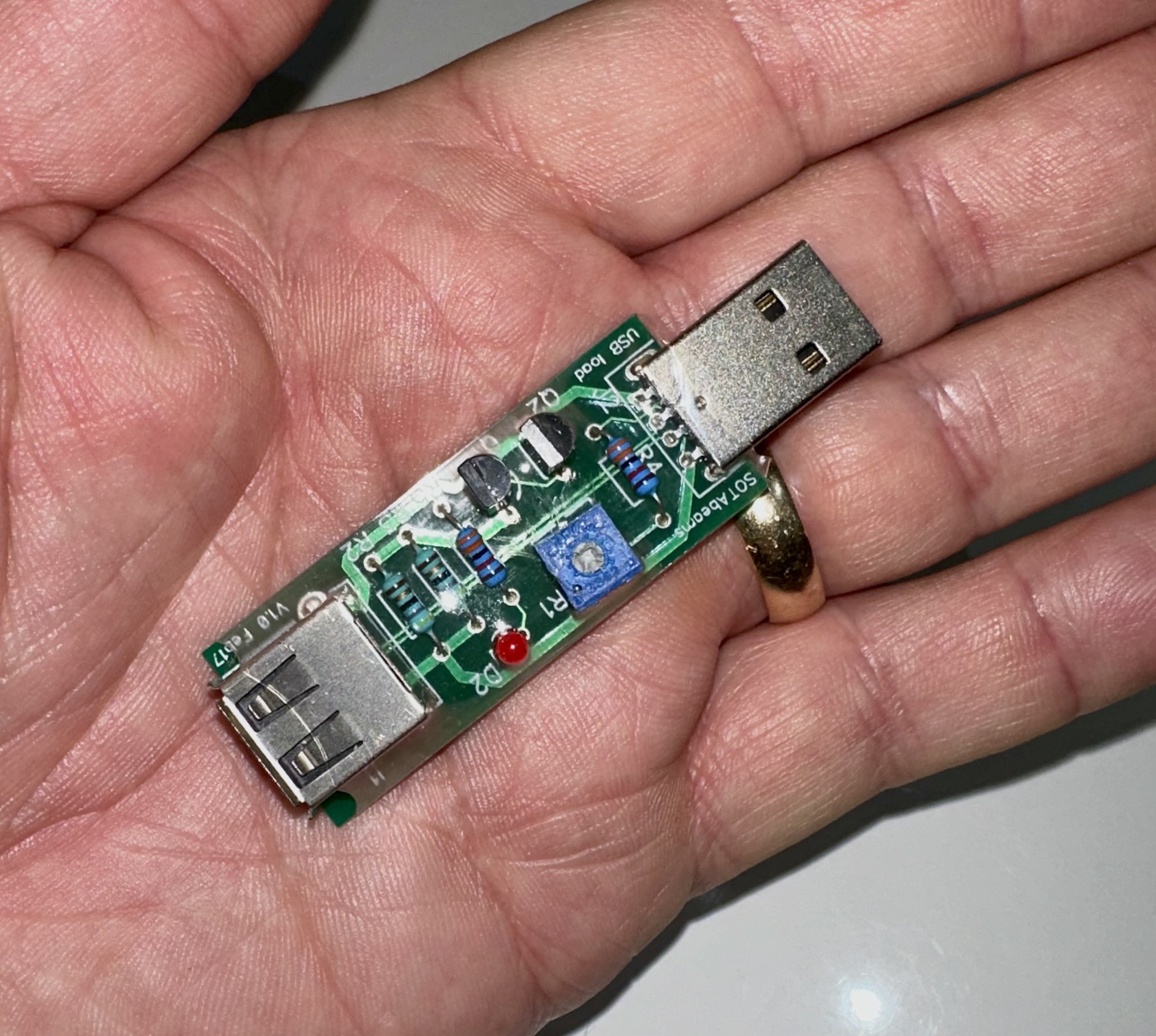
The power comes from a 3000 mAh 5v power bank. However the problem here is that the power draw from the WSPR unit is so small the power bank will some times close down, and for this reason I have had to build a small usb circuit that creates a minimal demand on the power bank keeping the power supply constant. With this power bank and the WSPR unit on its high setting I can easily get 16 hrs of continuous use. When I work on the lowest setting I can achieve 3 full days (72hrs) of use.
And that’s about it, all this kit can fit in a small unobtrusive bag or box.
Operation
First and foremost the transmitter connects to a computer where you can access all the parameters of the unit and set it up how you want your operate, power, duration and frequency etc. The unit already has inbuilt filters for the 20mtr (14Mhz) band so you don’t need additional filters if that is your band of operation. Once the programming is done you can now set the system up in place as you want it. I sometimes use this from my loft to see just how well certain bands are working in certain directions at different times of the day.
The battery connects to the transmitter that in turn connects via the filter to the Antenna tuner unit. the antenna unit connects to the antenna.
Timing has to be precise when setting up, you set it to transmit at every 2 minute interval.
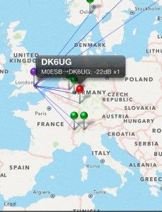
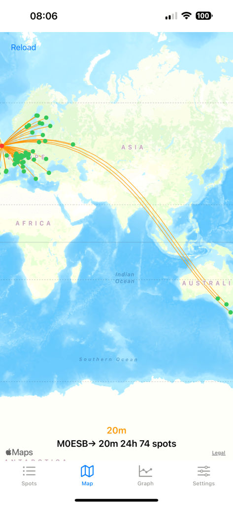
Once you are transmitting it’s worth leaving it be for about 30 minutes and then you can pop on to WSPRnet to check your signals. You can check what is being received and what strength of signal is getting through to your destination .
I use an app called WSPR watch that connects via the WSPRnet system so I can monitor my performance from absolutely anywhere just by using my mobile phone or iPad. How convenient is that? I can leave the unit unattended and monitor it remotely.
In summary the WSPR protocol uses a very weak signal to test atmospheric and solar cycle conditions to determine a viable route for a signal to reach a destination. if you were to listen in at the destination all you’d probably hear is white noise, however the decoding program is so accurate it can pick up a signal to noise ratio of as low as -28db.
Im leaving it there as I could ramble on for ages. If anyone for some strange reason wants to know more then please get in touch.


You must be logged in to post a comment.