Sharp OZ-7000 Wizard

The Sharp OZ-7000, Amongst one of the first electronic organisers and precursor the PDA. Needs repair. Or does it?

What the listing stated:

Not working. I have replaced the two batteries and cannot get it to work. I have not touched the memory battery. See picture for actual item. Case is a bit sticky unfortunately with age.

EBay

First of all, what is it?

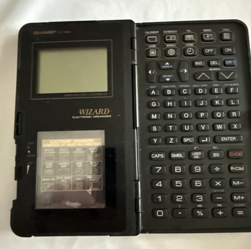
The Sharp Wizard series, introduced by the Sharp Corporation in 1989, was among the first electronic organizers and a precursor to personal digital assistants (PDAs). The debut model, the OZ-7000 (known as the IQ-7000 in Europe), combined organizer functions with an IC Card expansion system, allowing users to install software and memory cards. Over time, Sharp refined the series with larger displays, increased memory, and enhanced features, such as infrared communications port for wireless data transfer, touch-sensitive displays, and clamshell designs.

The out-of-the-box functionality of the OZ-7000/IQ-7000 included a memo pad, a telephone pad, calendar and scheduling with alarms and repeating events, multi-time zone clocks, and a calculator, thus covering all the basic functions found in PDAs since. The keyboard was not QWERTY, although later models, starting with OZ/IQ-8000, changed the orientation of the screen and keyboard layout.

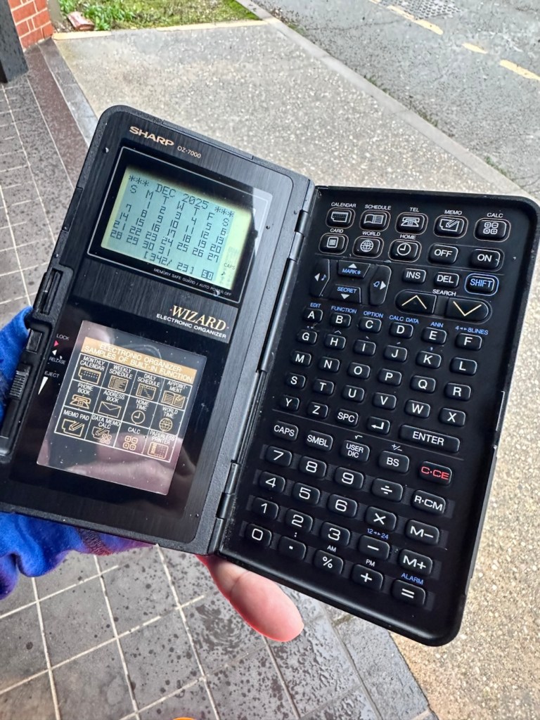
The OZ-7000 was about 6.3 inches (163 mm) tall, 3.7 inches (94 mm) wide closed, 7.25 inches (184 mm) open, and 0.85 inches (21.5 mm) thick closed, making it much larger than later PDAs. It featured a serial port (proprietary connector) to attach to a Windows PC or Macintosh or another OZ-7xxx/OZ-8xxx device, an optional thermal printer port and a cassette tape backup. The OZ-7000/IQ-7000 model featured 32 kilobytes of internal memory and a 96 x 64 dot (8 lines x 16 characters or 4 lines x 12 characters) black and white LCD with controllable contrast but without a back light. A major advertised feature of the model was the IC Cards expansion slot for accessory cards developed by Sharp.

Wikipedia

A bit of a break from the mountain of photographic equipment I have been dealing with lately, I thought I’d take a bit of a detour and have a look at some prehistoric PDA gear, as I have also done in the past, as you will no doubt be aware of, if you have ever read any of my posts on Psion organisers.

From what I can gather, this one is a little beaten up and battle scarred, and quite simply does not work. I’ve paid the princely sum of £8:54GBP after i managed to knock the seller down by a few pounds. I just now have to await its arrival before we can carry out a thorough assessment.

Assessment:

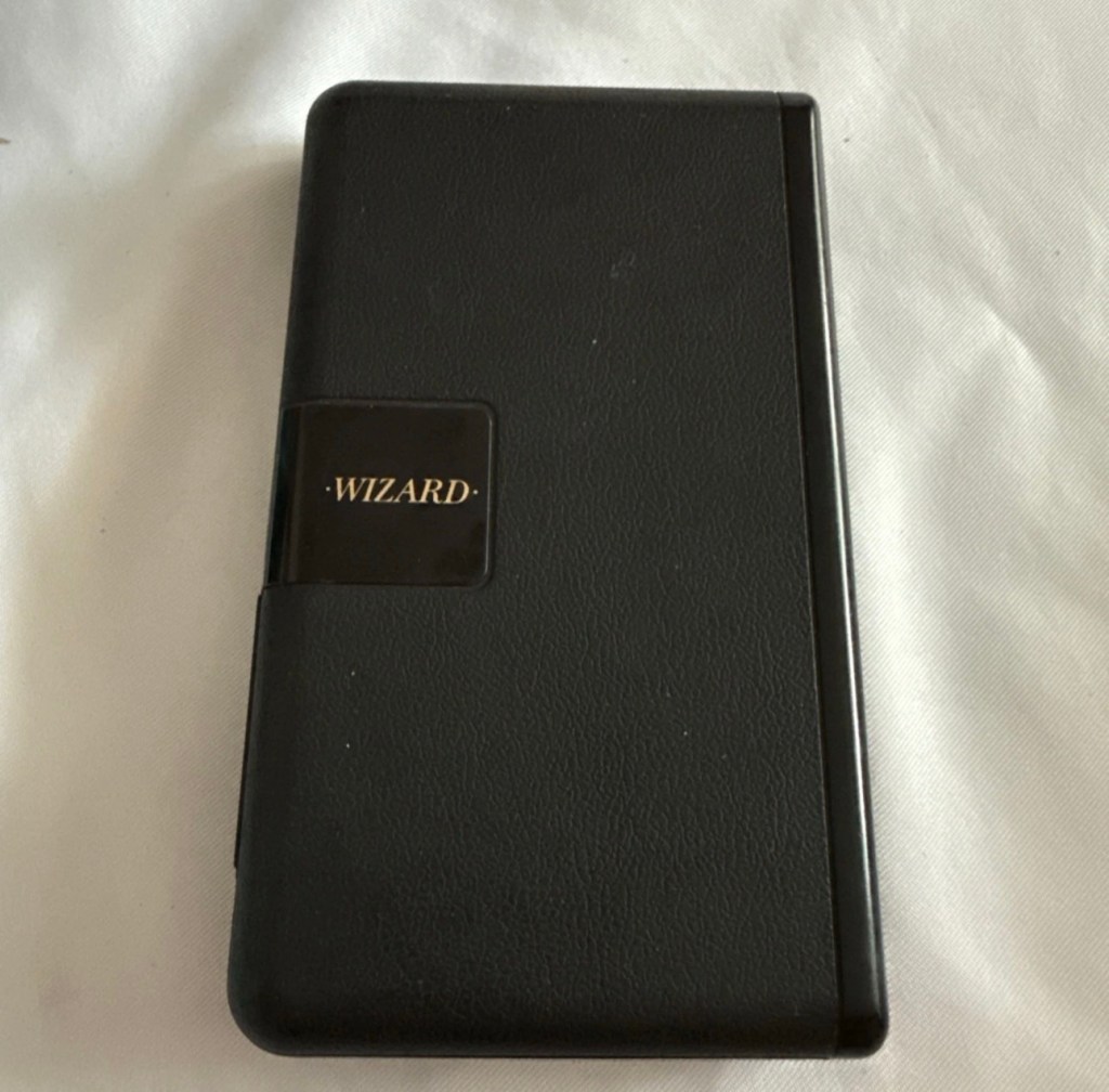
Its here, everything is as it should be apart from the base being a bit loose in one corner where the clip inside has broken, however that’s not an issue and can probably be repaired.

The broken clip

The exterior is a little sticky but again, this is just one of those 1989 rubber enhanced products where the vulcanised rubber coating has started to degrade. A post I previously published shows how I deal with these 80’s degrading rubber issues: Sticky, Rubber camera grips

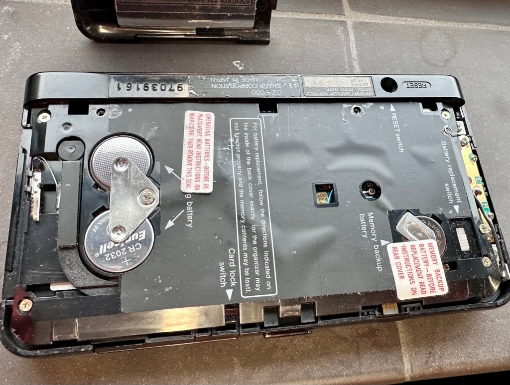
The unit has three batteries, under the rear shell. These are two CR2032 and one C1616 coin cell, with the C1616 being the units memory battery. These batteries will need to be tested as this unit does not start up, the whole unit is dead. The previous owner has stated that they have changed the two main batteries but not the memory battery, testing them will tell.

The three batteries

Beyond that, all catches, buttons and switches seem to be performing as expected, no cracks or major damage to the external shell, or screen area. Naturally there are signs of usage as you would expect on an item that is now 36 years old, light signs of age related wear and tear, nothing of concern that is detrimental to its operation.

Repair:

I’m leaving the broken clip on the rear shell as it is, it’s not visibly exposing anything of the interior and to be honest needs quite a bit of force to show the gap, it’s not a problem and not necessarily requiring a repair. In normal handling it is not even noticeable, so it will remain as it is.

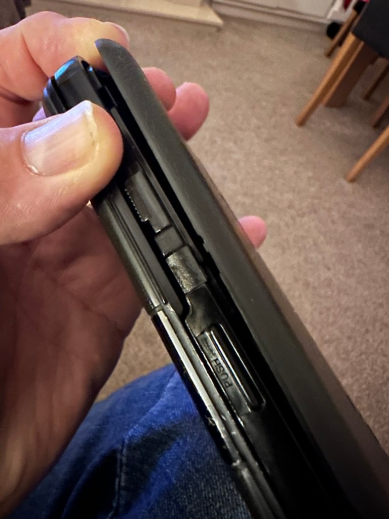
The main fault, and I apologise in advance, as it was not really a fault, was a misunderstanding of the unit’s operation by the previous owner. When you take the back off and change the batteries, you have to operate a switch so as to not interrupt the backup of the system.

Battery backup switch there is a “B” and a “A” setting

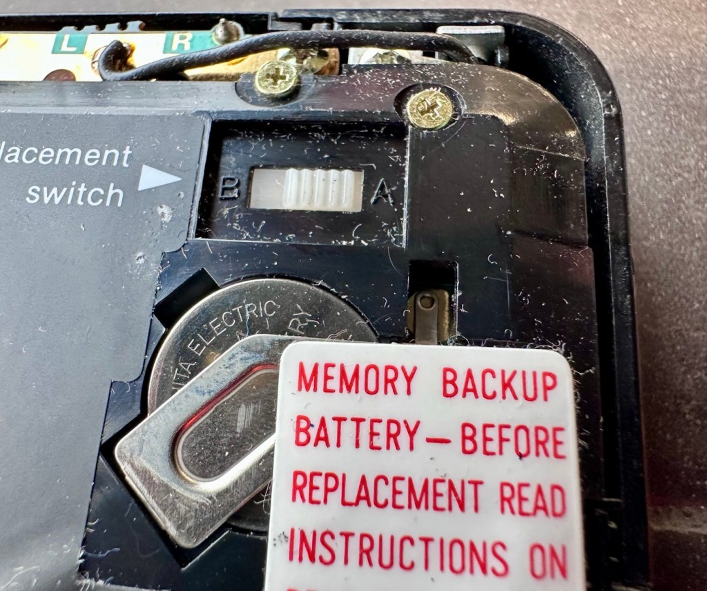
There are two modes and these are explained below. This switch is located inside the battery compartment and is used when replacing the main batteries to prevent data loss.

  • B stands for Backup, a setting used during the battery replacement process. The device relies on a small, separate backup battery (often a C1616 coin cell) to maintain memory while the main batteries are removed, provided the switch is in this position.
  • A stands for Active (or simply the normal operational position), which is the standard setting for everyday use once new batteries have been installed. 

To replace the main batteries safely and avoid losing your data, you must follow a specific procedure that involves setting this switch to “B”, changing the main batteries, and then switching it back to “A” after the new batteries are inserted. 

The issue here was that the batteries had been changed and the switch was put into the correct “Backup” mode. However the previous owner had not placed the switch back into the ”Active” mode when the batteries were changed and the back of the shell was put back in place. Hence the unit would not work as in theory the batteries were locked out of use. On opening the shell up, this was the first thing I looked at, and when the switch was put into the correct position the unit sprung into life once the “On” button was pushed.

When the switch was set, power applied and the unit reset to 1989

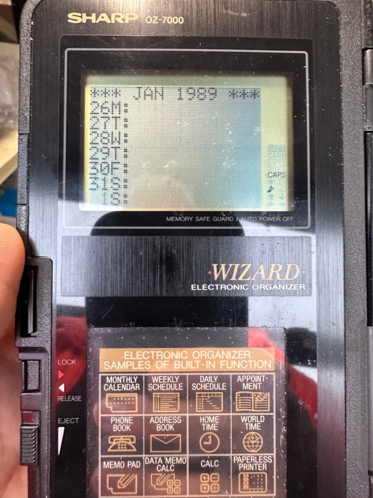
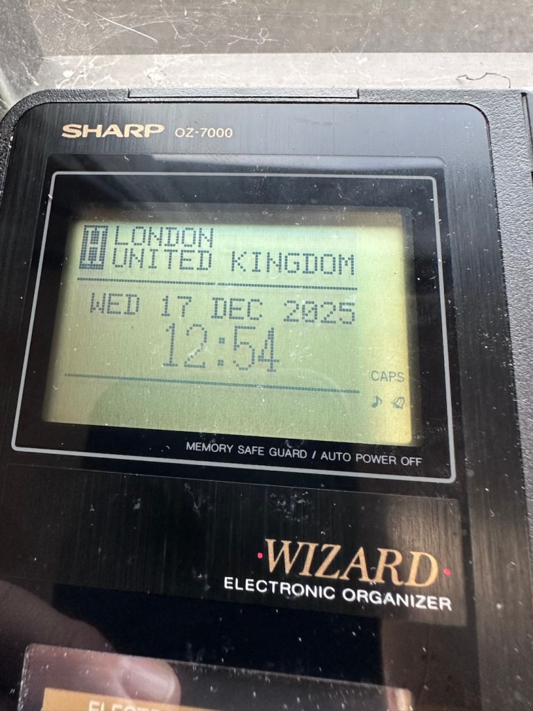
When the unit was turned on it then reset to 1989, I was able to change the times and date, and I was pleasantly surprised to find out that the date range on this unit covered the years 1901-2099. Considering this unit was released 11 years prior to the Y2K bug of 2000, it showed some advanced thinking in the implementation of these units.

One of the issues with this particular unit is that there is no backlight on the display, the display is black and white and the only change that can be made is to the contrast. Back lights eventually arrived with later models. So use of these units was pretty much limited to daylight hours, or whilst under a light source of some kind, that said the display is very good and has a good contrast range.

The unit with an example function card installed
In use in the carpark at work

The last thing I have done is clean with some IPA to remove the years of gunk and I think this was quite successful

The IPA certainly lifted some dirt

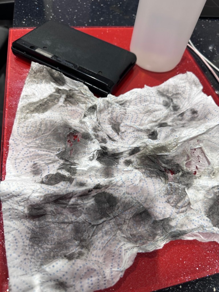
After this I have finished off with a nice polish with some car cockpit cleaner. It’s finished this repair off just nicely.

Result:

Here we have a nicely presented, clean and fully working example of a nice little bit of personal computing history.

Has come up lovely

So. With these older items, it’s sometimes good to just have an awareness of how these old timers operate. Get an instruction manual, study how it works, it can make the difference between selling it as damaged, when in fact there really was nothing really wrong with it. The seller could have sold this for 3 or 4 times the value that I purchased it for, but I’m not worried about that, as far as I’m concerned I got myself a bargain and to be honest, that doesn’t happen that often.

It’s a win win situation as far as I’m concerned, I win as I now have a lovely example of pre PDA technology, and it’s a small win for the environment as another piece of “Waste” has been saved from landfill.

Thanks for passing. Thanks for being there. Always appreciated 🙏

Modified Sega game gear 2110-50

You may wish to refer to this post: Sega game gear 2110-50 where I purchased a non working Sega Game gear and brought it back to life.

The (I thought it was repaired) Game gear

I’m now ready to do some modifications on this unit, and I will save the replaced items for use on later projects.

Pretty much every Game Gear that was ever produced (and that is approximately 10.6 million units) has suffered with the dreaded (Capacitor plague) that I have discussed in an older post. The first job that is recommended to be carried out when purchasing an old Game Gear is to replace the old capacitors, it’s quite an easy task and nine times out of ten will remedy any issues that you have and allow you to continue gaming for years to come.

However there are other issues.

The screen is an old tube powered system that is exceptionally power hungry, you can replace this with much superior LCD versions, I’m withholding from doing this at the moment as I want to get as much use out of the old screen, and to be honest my unit doesn’t require replacement just yet, there’s still life in the old girl. I’m sure that this will be a future project though.

Occasionally after doing the capacitor replacement on the power board, other components such as a small IC and three transistors that control voltages across the system, start to misbehave causing the unit to switch off after just a few seconds. This is currently occurring with mine and I am intending to replace these components to see if this sorts out my issue. I have also ordered a replacement power board from China that is a fraction of the cost of a European one, it may work, it may not but if the change out of components dosen’t work at least I’ll have an alternative option.

There are a few checks we can do prior to replacement of these components on the power board that will confirm the various voltages required by the system. It’s best that these tests are done prior to diving in head first to replace them. You could be just wasting time. You may need a new power board or maybe even consider converting to a rechargeable battery system. It’s all doable.

Expected voltages – photo courtesy Retrosix

Here are the results from my test of voltages on the power board, I’ve injected 9v via a bench power supply to the battery contacts on the board:

  • At the 34v pin I had 0v
  • At the 9v pin I had 8.9v
  • At the 1.28v pin I had 1.28v
  • The three ground pins read as ground
  • At the two 5v pins I had 0v

So as a result I obviously have an issue with the 5v rail and the 34v rail, I believe the 5v rail is the one that affects the boot sequence and the 34v is not an issue at the start up, however, it’s there for a reason and this simple test proves there is an issue. I will therefore only change the IC and three transistors as the capacitors were changed when I did a full recap.

For my modifications I am getting a new clean amp duo audio board with dual speakers instead of the single mono one that is standard. This is an upgrade on the original, extremely efficient and with better sound processing.

I am also replacing the shell with a new Blue case and glass to replace the scuffed old screen, this shell also has dual speaker outlets to compliment the audio board replacement. The shell is already prepped to accept a rechargeable battery system should I decide to install it at a later date.

I shall be getting these upgrades from Retrosix who specialise in supplies and modifications for gaming consoles.

All the items have now arrived and the first thing I’m going to do is sort out the replacement IC and transistors on the power board. The rest is fairly straightforward. However they have sent me the wrong shell, a single speaker one instead of a dual speaker one, so I’ve now got to await a replacement, annoying!

Scratch that, they are saying that they never did have any duo speaker ones even though they were advertising them on their site ( as per picture above..) and after a protracted discussion with the supplier / owner i’ve come to the conclusion that he might think he is a wizard at modding and designing circuitry but is totally and utterly inept at customer service, he wouldn’t know good service if it bit him in the ass. Hey ho on we go, it is what it is.

If you choose to use them in the future then just be aware. They have an uncanny knack of trying to pin their inadequacies and mistakes on you, the customer. Caveat Emptor – as they say.

So now the sound will be original mono, but hopefully improved. I have a spare speaker and mount as a result and I can use the new clean amp duo board in a mono configuration. Should I get a duo speaker shell sometime in the future I can always do a swap out.

Today I’ve taken the empty new shell and installed the new audio card and speaker, as well as the new buttons and silicon pads. I’ve then installed the main board minus the power board that still needs the new components.

I’ve also installed the new front lens on the unit and I must say it looks nice.

New front lens on unit

Let’s get to the difficult bit, replacing the components on the power board. I’m not joking when saying that some of these items are not much bigger than a grain of rice. I suspect a lot of bad language will be used here, as this is a new level of soldering for me. I’ve never replaced anything so small before. If I balls it up I’ll just have to await my cheap Chinese power board.

Ok, the power board from Ali Express got here really quick, to be honest even before I could set some time aside to change the components on the old board, so therefore I’ve decided to try this new board as a straight swap.

I will keep the the components and the old board to use at a later date.

First though I have used the bench power supply to test it is ok, and it’s a big tick on all voltages as per the test I did on the old board. All voltages are stable and consistent, so I have secured the board in place and put the required batteries inside. Works perfectly.

Back together, awaiting the big switch on
Working perfectly

I now have a perfectly good looking updated Game gear that I am exceptionally pleased with. The sound system is a good upgrade, it has a really loud volume (adjustable) and is crisp. The powerboard from China at a total cost of £10.80 is an absolute bargain, and works perfectly with good stable voltages. The case is good, fits well and the lens is clean easy to install and scratch free, the whole thing looks brand new.

Two old rebuilds, rejuvenated

I now have two perfectly good looking and working examples of 90’s retro rivalry in perfect working condition. The plan is to display these in the house, on a custom made display. I’ve really enjoyed working on this little project and I’m made up with the outcome.

The only things left to be done would be to change the power supplies to rechargeable and to change the screens to new IPS/LCD screens, but I don’t think I’m going to do that on these two, I’m keeping them original or as close as possible to original, I want to keep these as they are, to cherish in this condition for as long as I can.

I love them. And they are fantastic.