HP Jornada 540 Series PDA Pocket PC

I have two faulty pocket PC units that I can hopefully combine into a “Frankenstein” unit. Can we get at least one of them working again?

What the listing stated….mostly AI produced I guess?

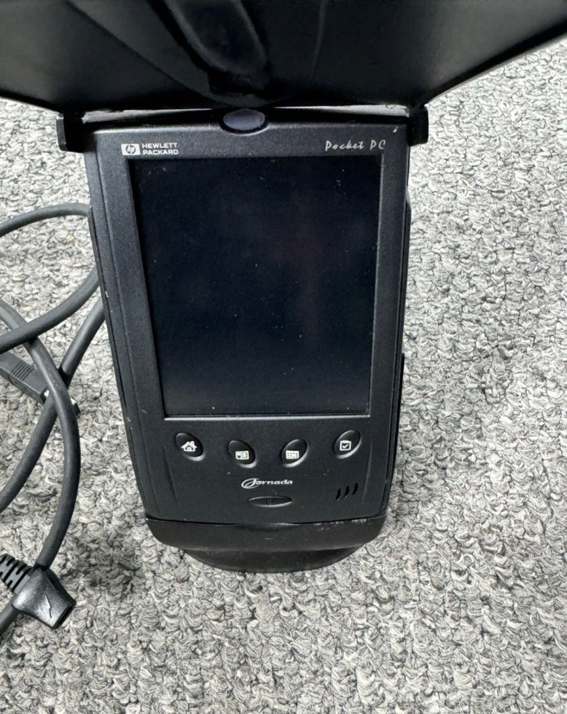
Untested, no charger, docking station only by Hewlett Packard

32MB Jornada PDA 540 Series Pocket PC Windows & Docking is a highly functional device that comes with some amazing features. This device is perfect for individuals who desire a highly efficient PDA Series. The device is sold as untested and is compatible with the Windows operating system. The brand of this device is HP, which is a well-known brand in the tech industry. The PDA Series is HP Jornada and it comes with an installed memory (RAM) of 16 MB. The display size (pixels) and screen type are unknown, but it has a model number of 540. This device comes with a docking station that allows ease of use for individuals.

EBay

And this is my original old 540 (548) Jornada.

I just know this is going to be a challenge, and to be honest i will have two of these when this one arrives. This is the 16 mb version, released in Mid 2000, currently aged at around 26 years old. I’ve had a dead one sitting in one of my junk drawers for a couple of years now and I though it would be a good challenge to get at least one of them working again, another one of my Frankenstein projects if you must. I have no charger for these, the chargers are priced at a premium with the online pirate community, (Robbing swines!) so I will just have to make do. At least with the docking station that this unit has I have somewhere to start from. I suspect both batteries will be dead so I may have to use some jiggery pokery to get some power into their circuits to see if we can get any signs of life.

But whilst we await the arrival of this unit, here is a little bit about this PDA:

The Jornada was a line of personal digital assistants or PDAs manufactured by Hewlett-Packard. The Jornada was a broad product line that included Palm-Size PCs, Handheld PCs, and Pocket PCs. The first model was the 820, released in 1998, and the last was the 928 model in 2002 when Compaq and HP merged. The Jornada line was then succeeded by the more popular iPAQ model PDAs. All Jornada models ran Microsoft Operating Systems that were based on Windows CE.
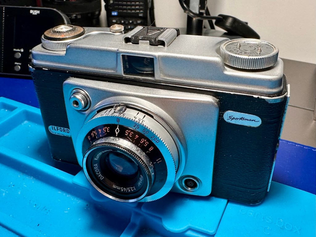
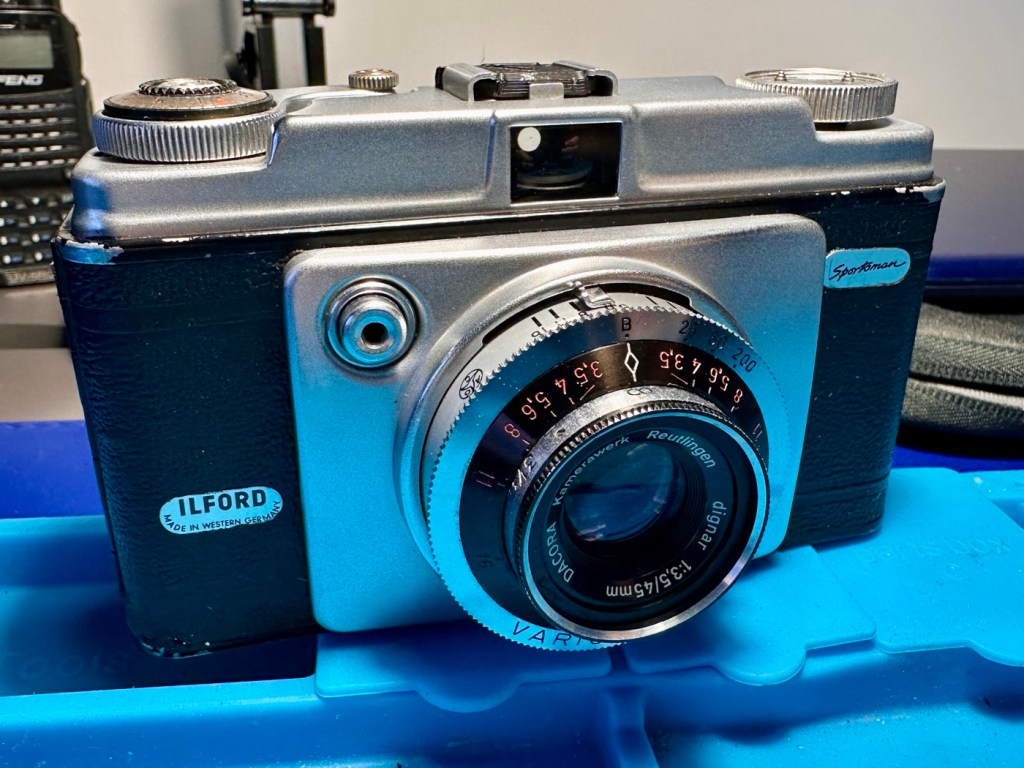
Jornada 540 series

The HP Jornada 540 series, including models 545, 547, and 548, was released in July 2000. As one of the original Pocket PC platforms, it featured a 12-bit color display, 32MB RAM, and USB connectivity running Windows CE 3.0.

The Jornada 540 series was one of the original models of Pocket PC, when the platform was first announced. Sharing the Operating System, CPU and memory card slot of the 520 series, it featured a 12-bit display (originally advertised as 16-bit display) and USB connectivity. Two models were made available that were identical except for the amount of RAM. The 545 had 16 MB RAM and the 548 had 32 MB RAM.

Wikipedia

Assessment:

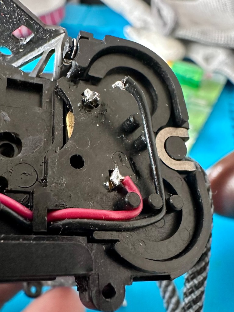
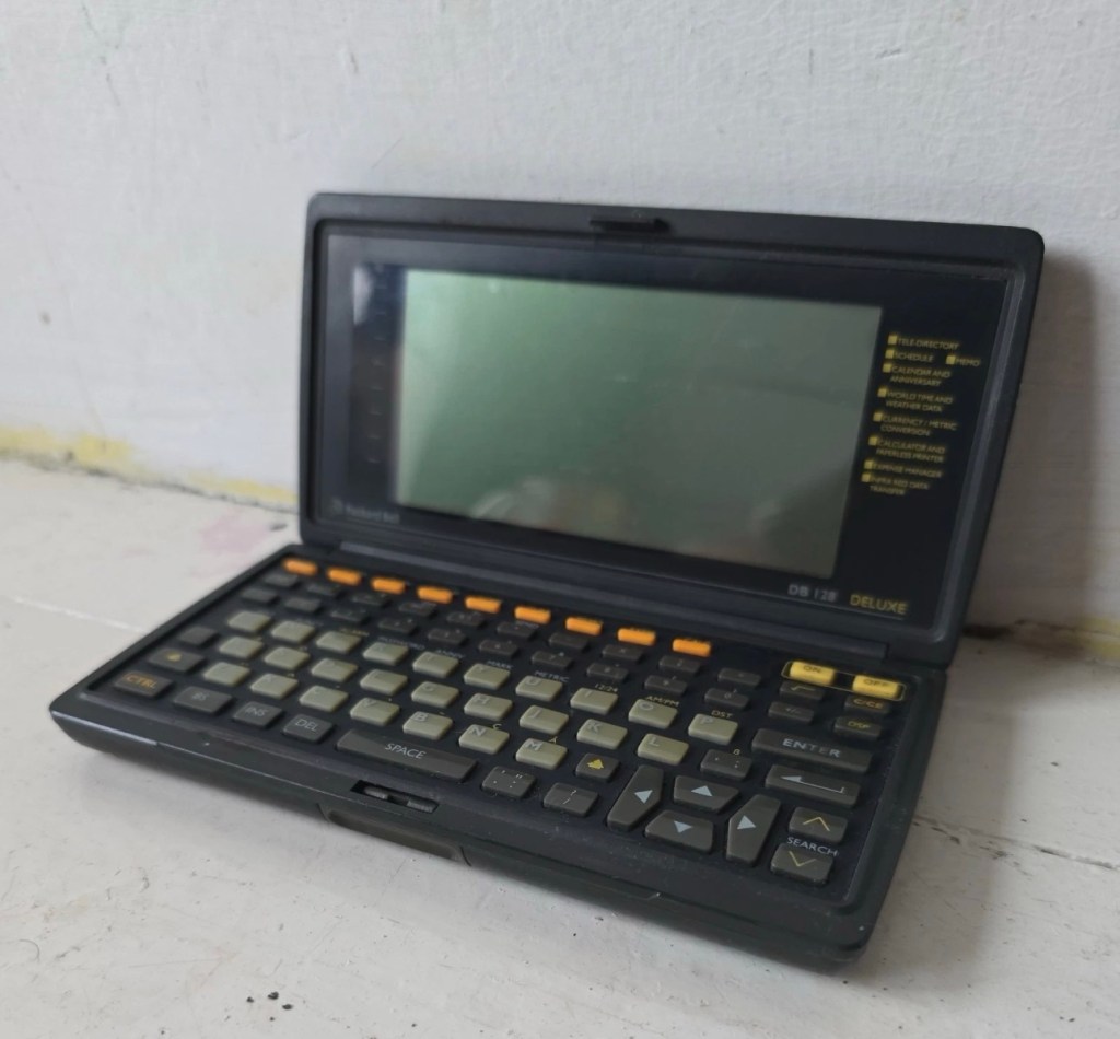
The old one I originally had is in fairly good condition, only displaying age related wear and tear. It has its original touch pencil, and is pretty much all there. Its battery (a 3.7v Li-ion) is very dead though (see pictures above) I have no means at present to see if I can charge the battery.

My original old unit

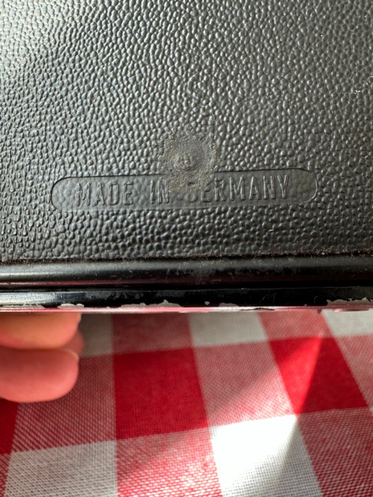
I have however found a charging alternative that will not break the bank. I have found a chap in Germany called Edgar, that runs a business selling cables and peripherals for older units, as well as more up to date systems, his shop is in Hannover and his company is: systemhauszakaria.com. I have managed to get a USB charging unit called a System-S USB Charging cable, that has the connectors required for this unit, and being a USB cable I can use a suitable plug for the mains supply , if required.

The System-S USB charger cable

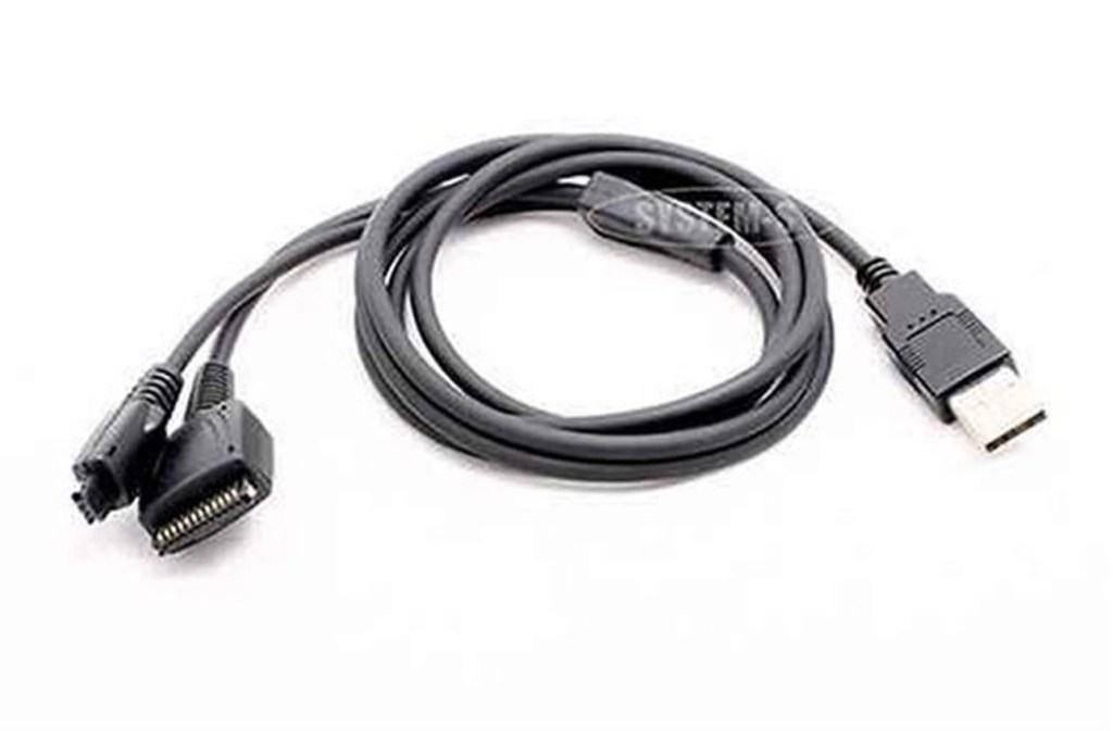
The cable includes a data transfer cable that also fits the unit, however my main task is to try and get some power into these units.

Let’s give it a go.

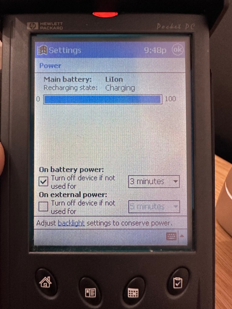
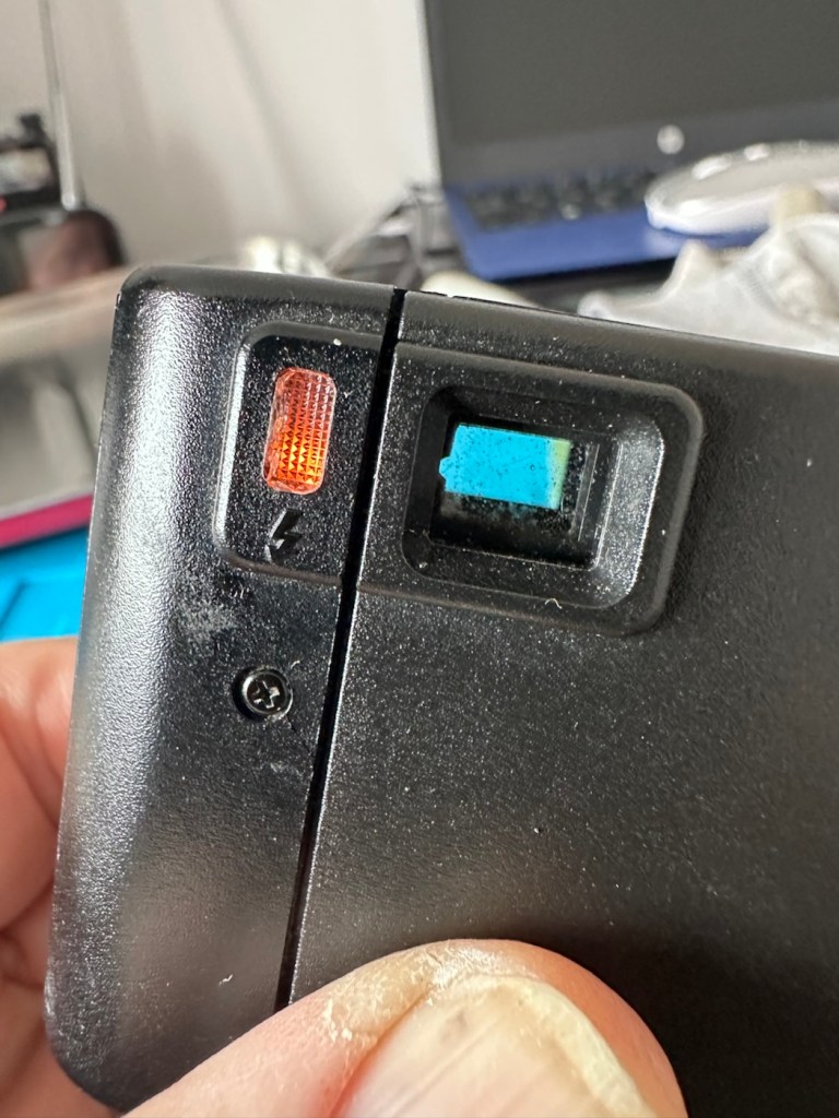
I’ve used the new lead, left the unit on and monitored it for about 90mins, and it does appear to be taking a charge. An Orange light indicates that charging is taking place.

Charging unit

The unit displays as 100% charged with the charging lead in. when disconnected it drops to about 50% but within a couple of seconds it shows as 100% again, this could be a time delay of some sort whilst switching to the battery circuit.

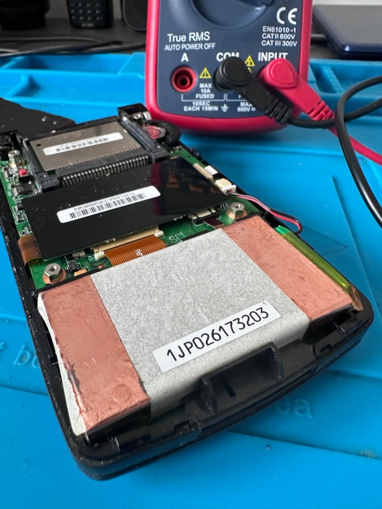
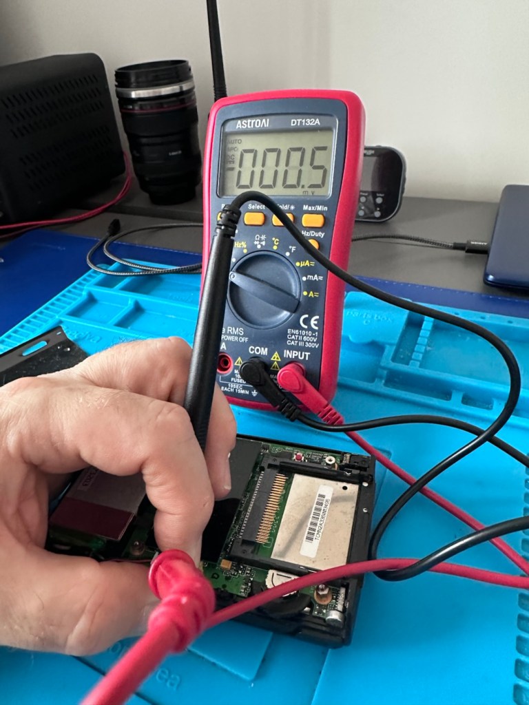
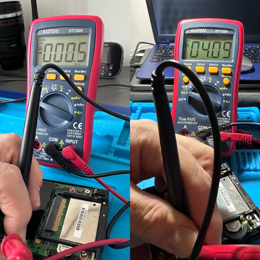
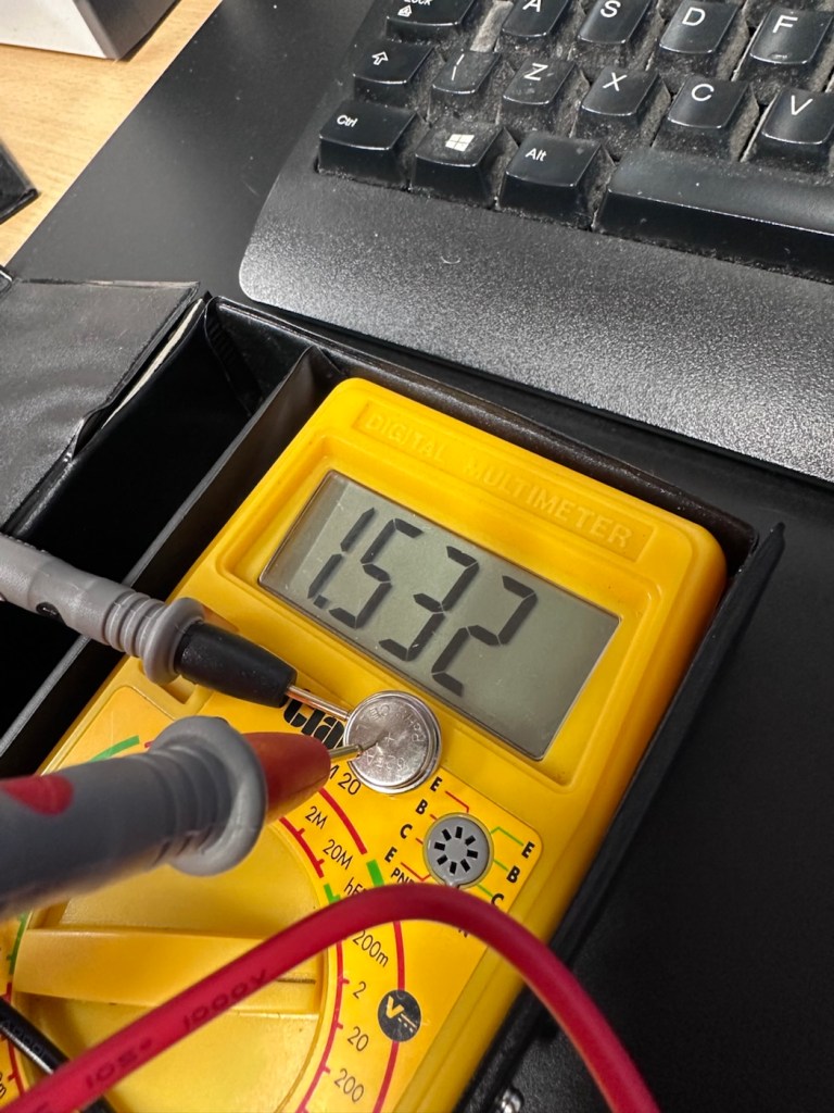
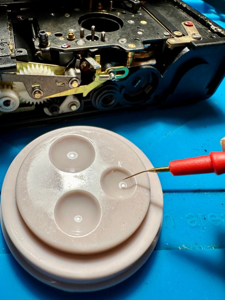
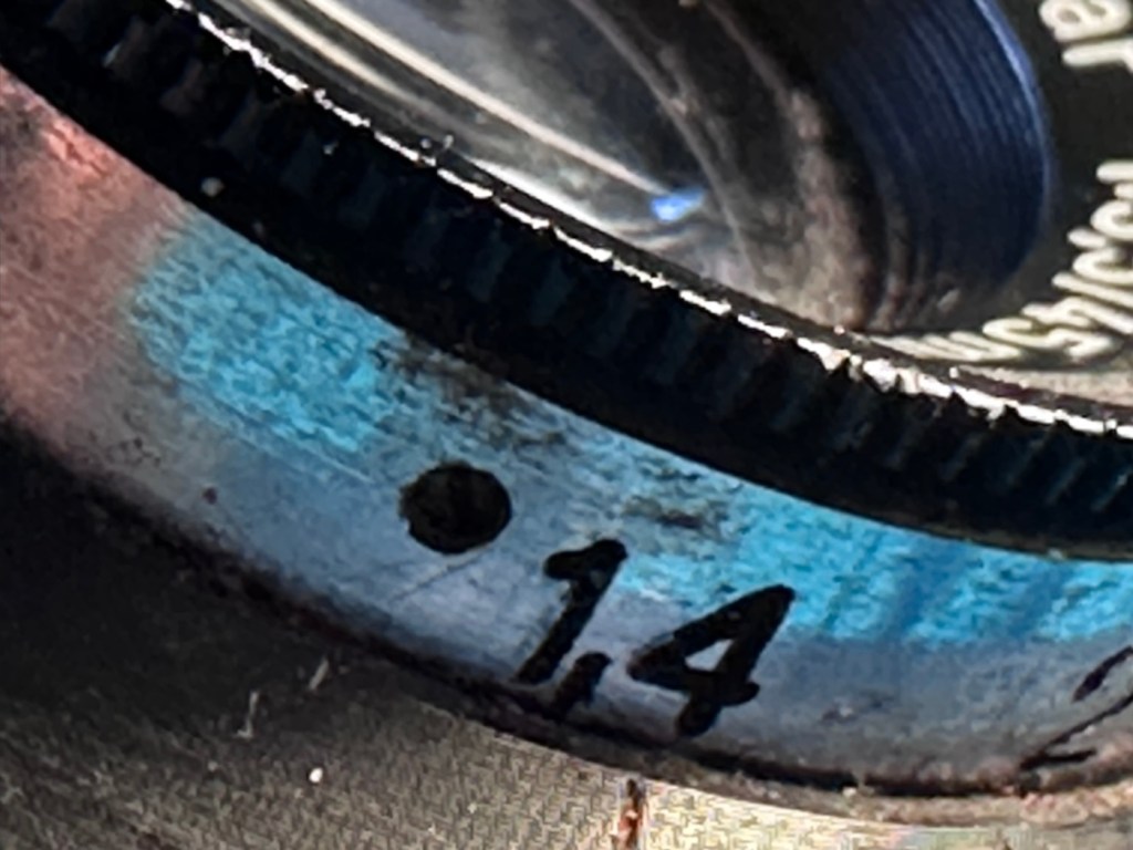
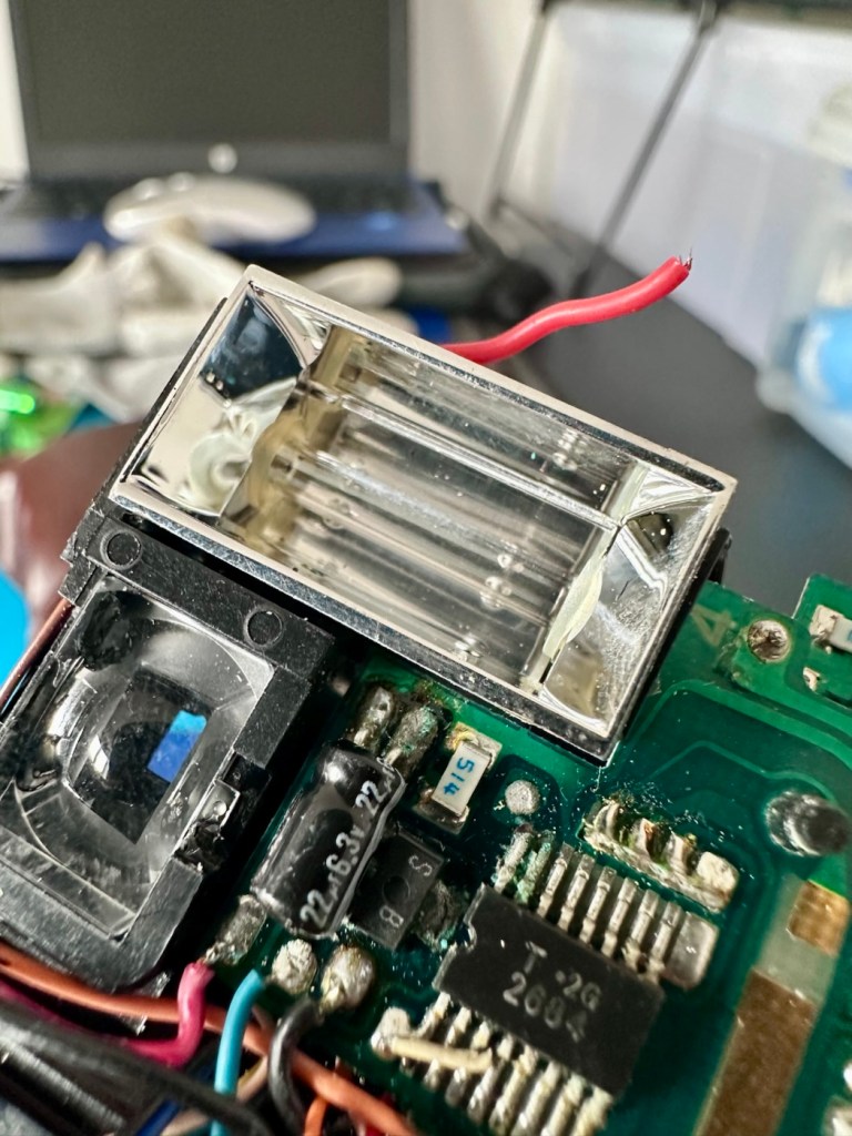
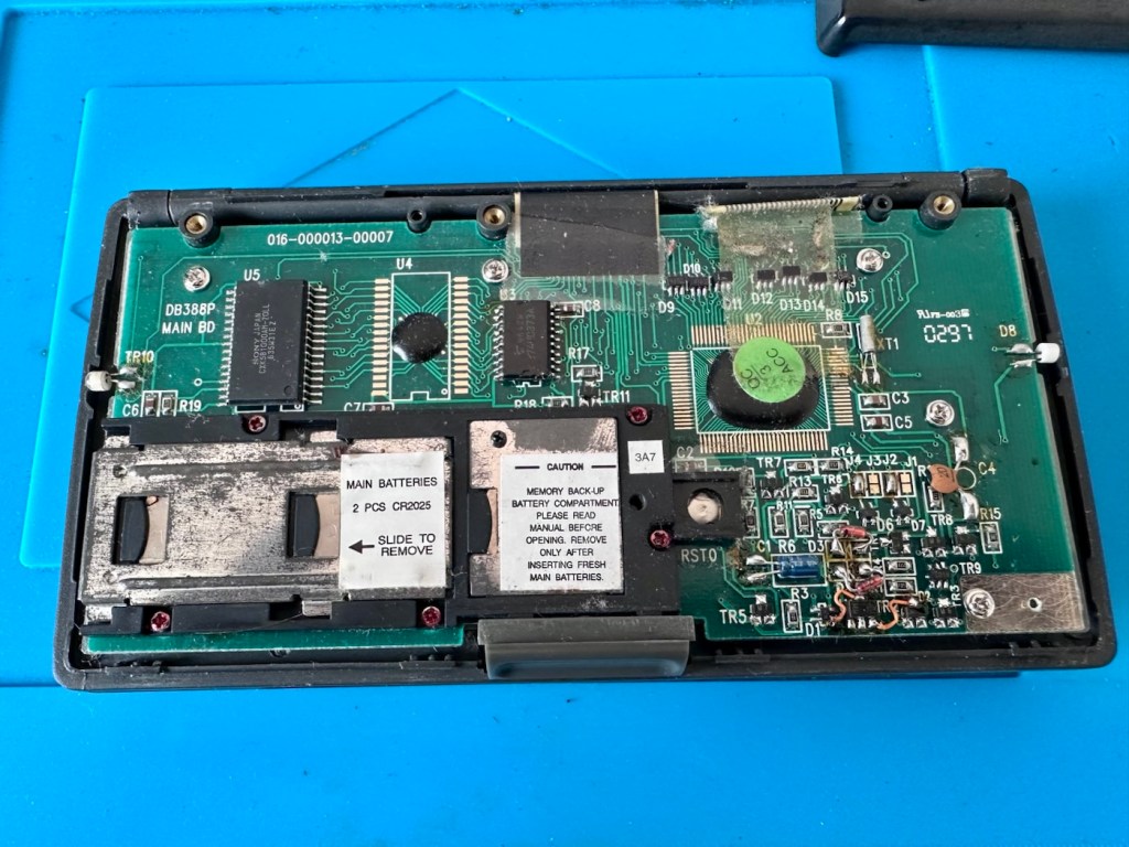
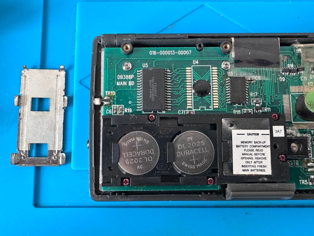
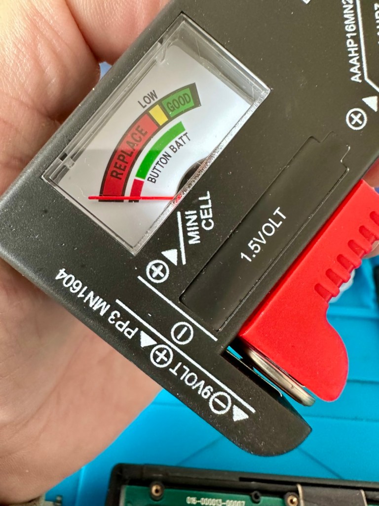
At this point I thought it would be worth getting the back off again, to check the battery charge. If you remember earlier in this post, this old unit that had sat unused in my desk for the last couple of years and when last tested the battery was dead at about 0.5mA. However this is a transformation, as when the battery was now tested its voltage was 4.09v. Now, a 3.7v Li-ion battery such as this should have a max charge voltage of 4.2v, so in theory this battery is in quite good condition considering its age. There may be a little deterioration, however considering this battery is possibly 26 years old it’s held up very well.

Before charge, and after

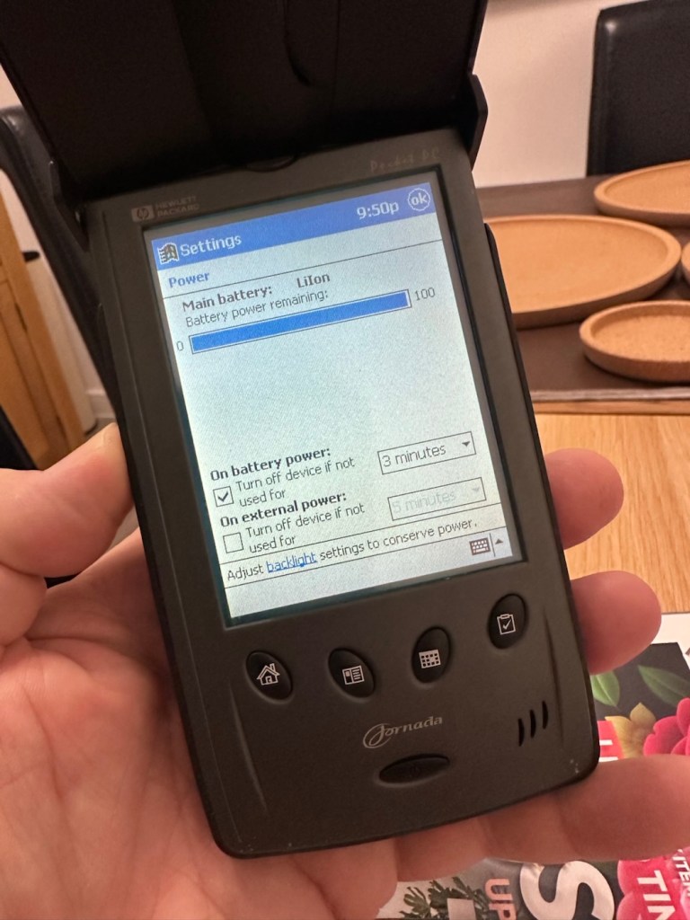
The unit will be left for a while to see how the charge holds. 10hrs later, untouched and off charge, I can confirm the power is still indicating 100%, this pleases me as it shows the battery is still good and has a good life inside of it. Very pleasing for what is potentially a 26 year old battery.

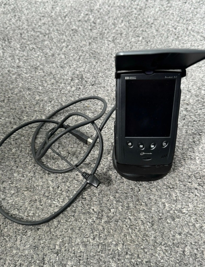
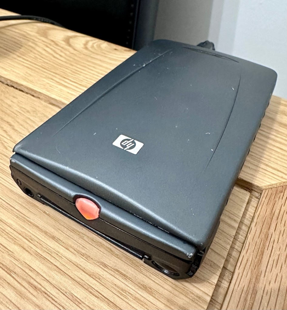
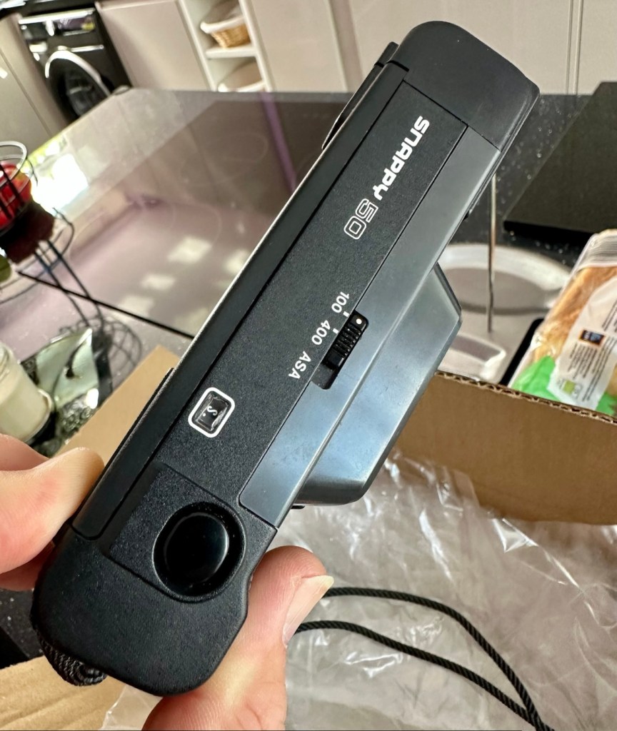
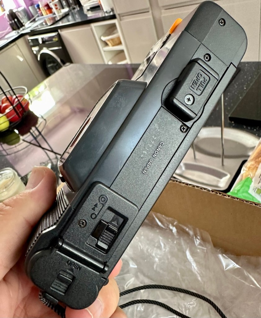
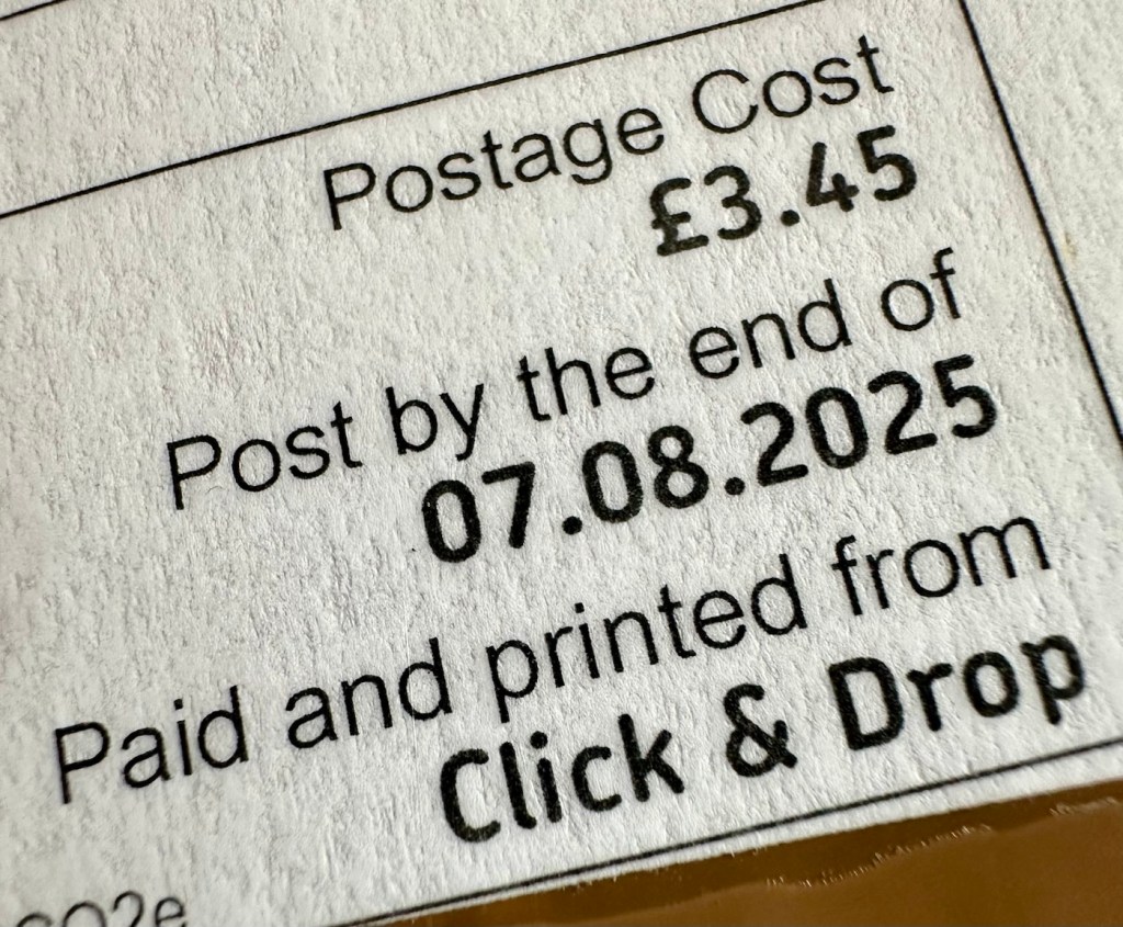
The new unit has now arrived and I’m surprised it got here after being posted in a couple of old carrier bags, no padding just a couple of old bags. I suspect the seller wanted it off his hands, they probably had little faith in it ever working again.

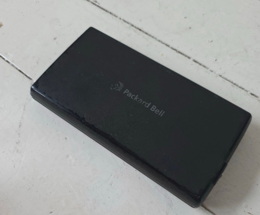
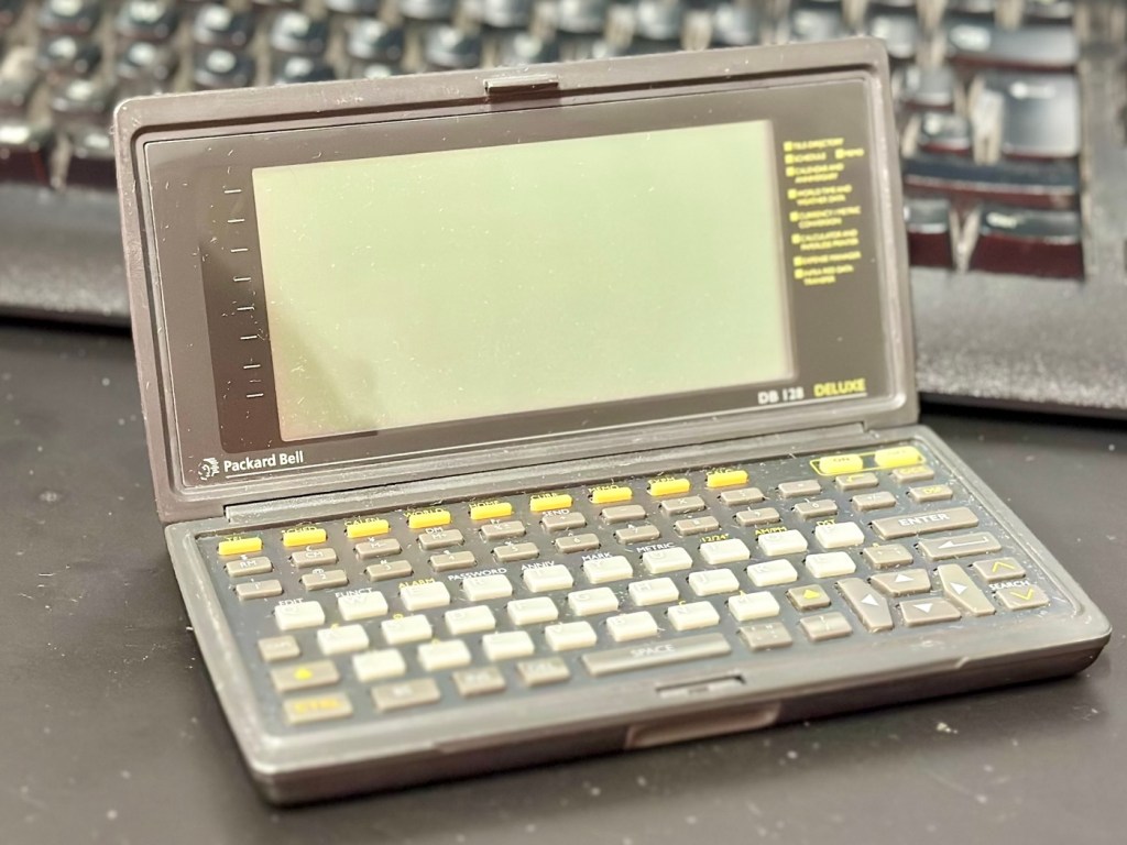
However, despite this, the actual unit appears to be in quite a good condition. It’s free from dinks and scratches and both the unit and the charging cable appear to be in a good order.

The new unit and charging cradle

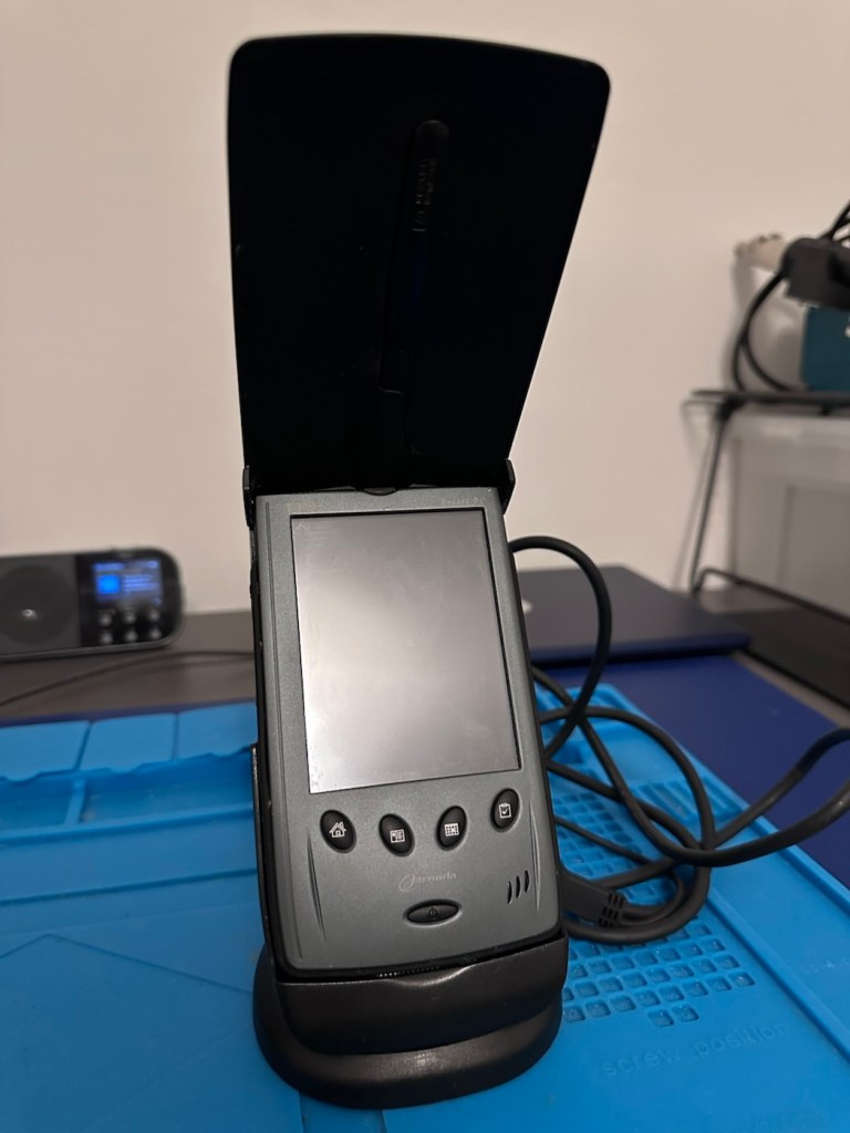
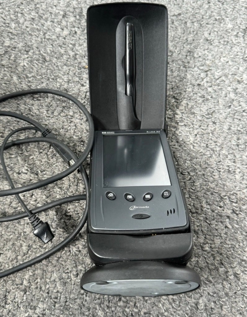
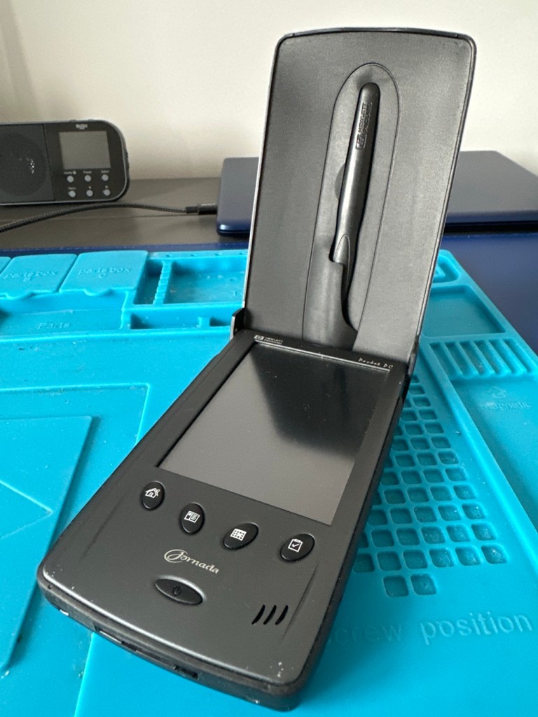
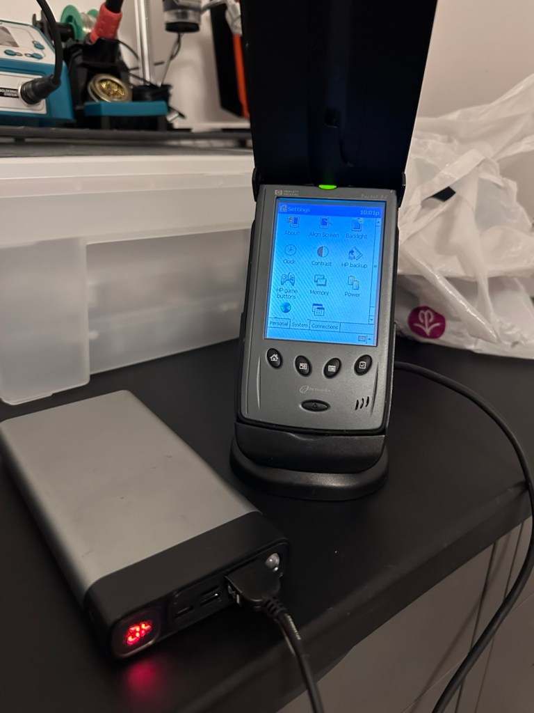
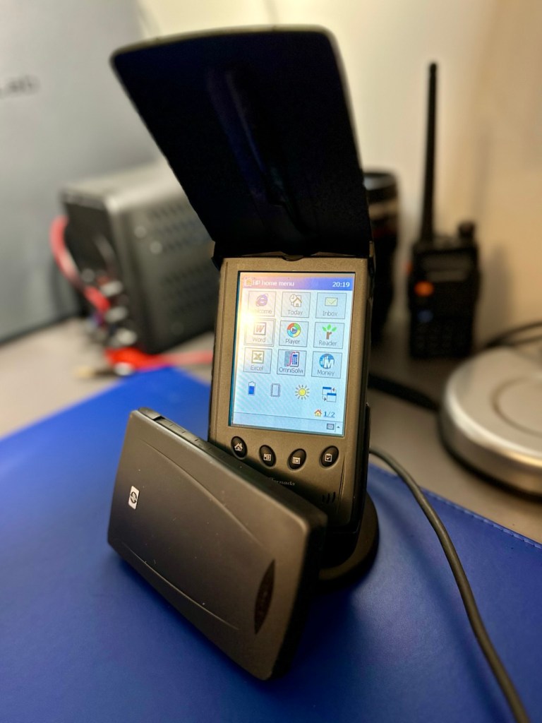
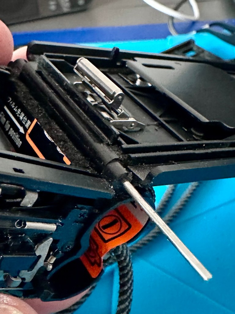
Now, the good thing is that both these units have their original touch pencils. This cradle has a cable connected to it and a USB socket, however that USB socket is for data transfer and not charging. To charge, the new System-S USB cable has to be connected in line. The cradle will then charge. And it looks as if it is doing just that.

This time i have connected the new unit and cradle to a Power bank charger to see if this works, and it appears to be doing just that. It drained the power bank quite quickly, it only half charged, I’ll have to put it back on the household power tomorrow to fully charge it and check its battery capacity.

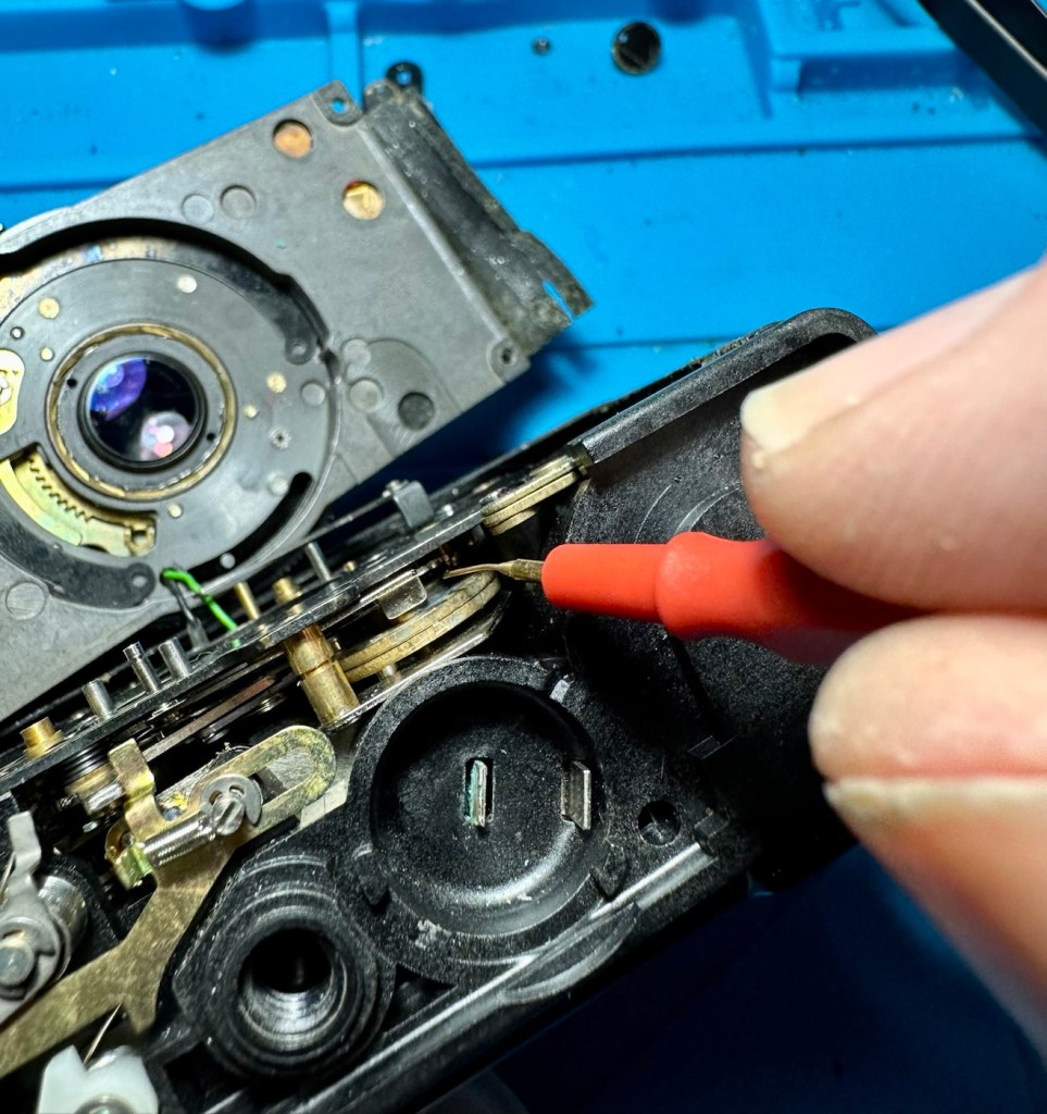
Tomorrow has arrived and the unit has been on charge for a couple of hours and it is indicating as fully charged. Back on the bench with the back off I can confirm the battery charge is reading at 4.08v so it is pretty much the same reading as the other unit.

New unit and cradle with power bank charger

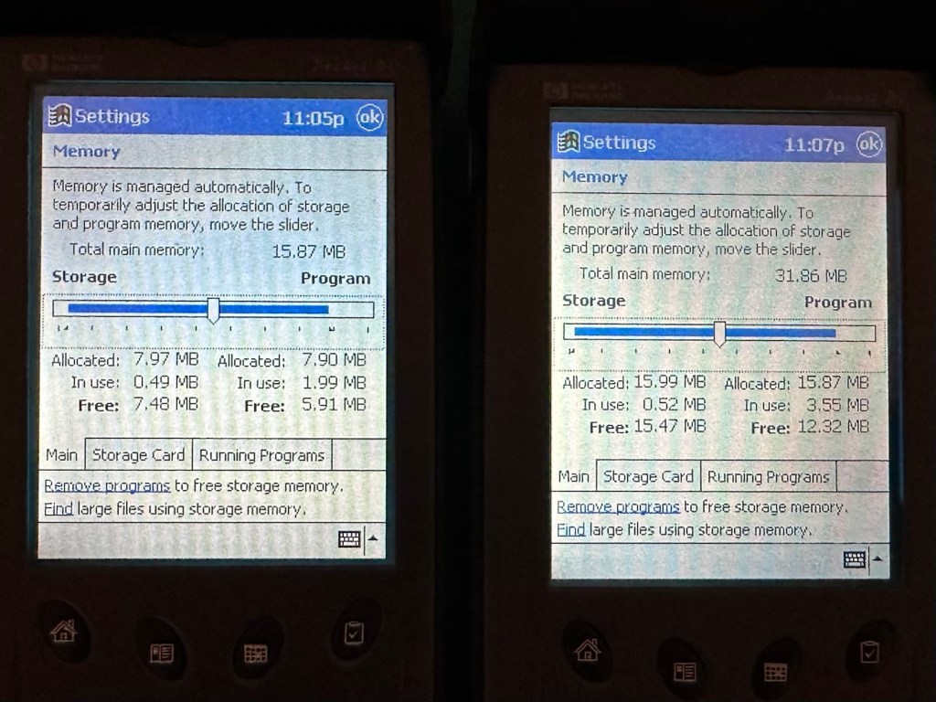
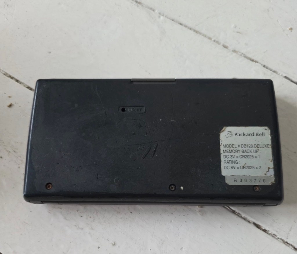
These two units are both of the 540 series however the newer one that came with the cradle has only 16MB of memory (The 545) whereas my older one (The 548) has 32MB of memory. It appears that HP created three variants in the 540 range and I now have two of them. The 545 had 16 MB RAM and the 548 had 32 MB RAM, the one that escapes me, the 547 was also a 32MB variant. (I’m going to have to get one now just to complete the set)
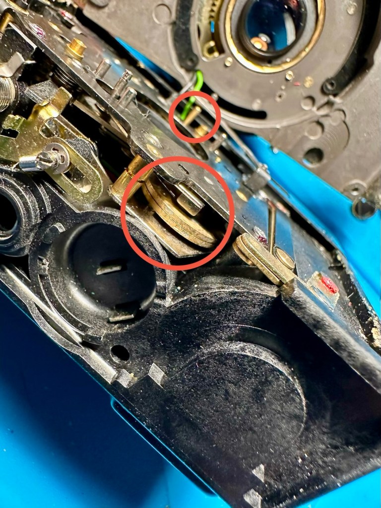
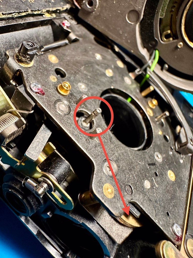
545 on the left, 548 on the right

Repair:

Less of a repair and more of a resurrection to be fair. I said it would be a Frankenstein project, and that’s exactly what it has been. Both units have charged well despite my concerns, they have been charged in a monitored environment and neither are showing signs of overheating, irregularities or any battery swelling or other issues. The battery management system on both batteries seems to be doing its job, and doing it very well.

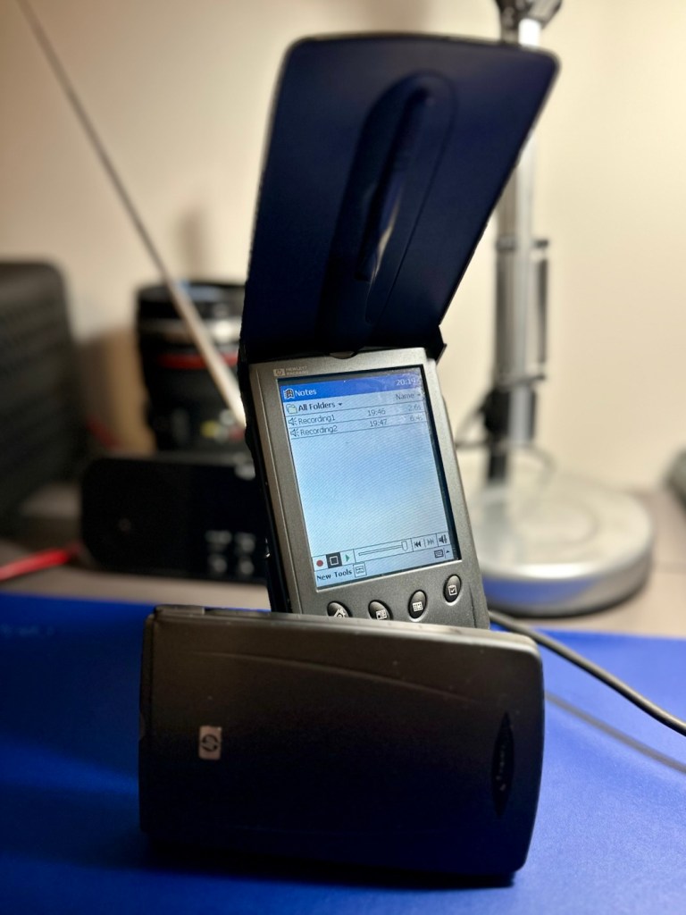
I’m going to use this section to test some of the functions, to look at the installed program package and at the same time monitor battery usage along the way.

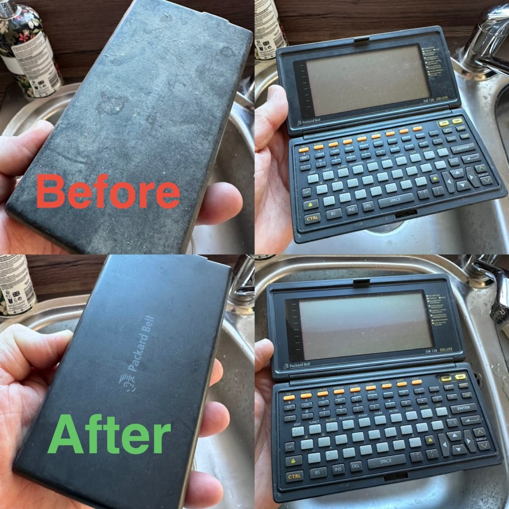
And as with all my projects, a thorough clean of the units is going to be carried out, it’s just got to be done.

But first I’m going to leave these units for a few days to see if the batteries drain.

Three days later

Three days later it’s good to see that when turned on, both units are holding a similar, slightly discharged reading that is to be expected. I’m pleased at this, and it appears that both batteries are holding out well and working very well after a long period of inactivity.

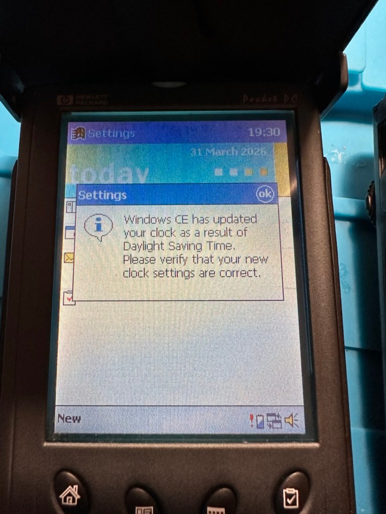
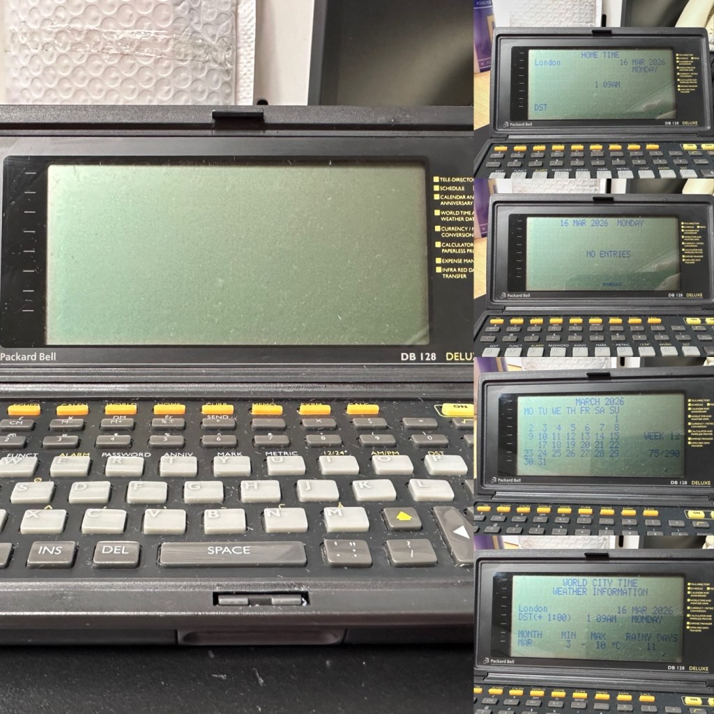
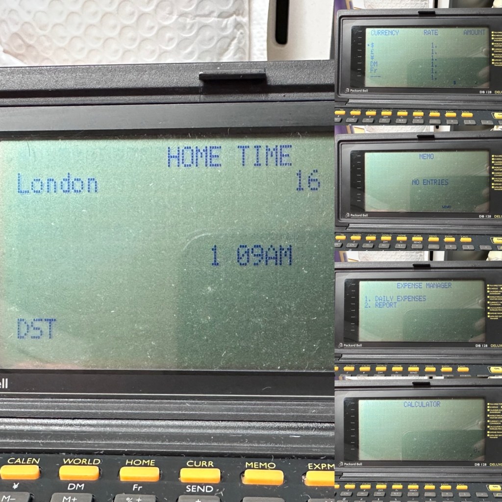
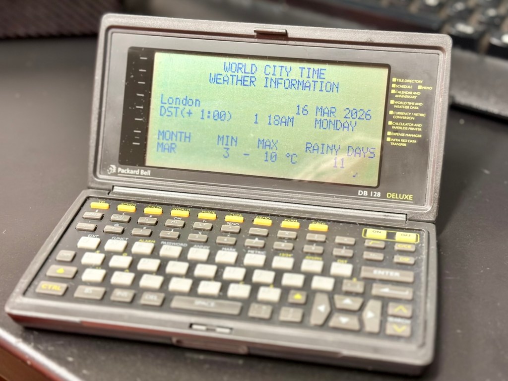
Left again for a couple of more days and both units are now prompting me to accept that the UK has now turned to daylight saving time, (as it has) and this is another good sign that shows that all is working as it should be.

What am going to do with these units? Please don’t ask me that as I just don’t know. I’m probably just going to use them for note taking, maybe for a to do list for my work room, but in reality they will probably just get stored in a sealed bag with some silica bags to keep them dry, until I either move them on or find another use for them.

Good job 👍

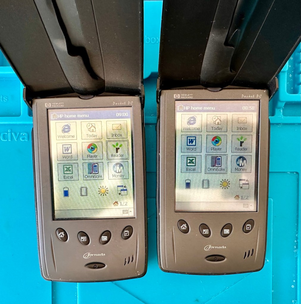
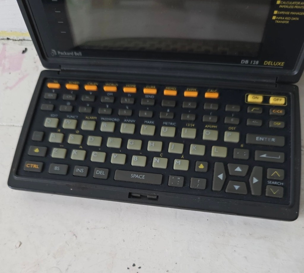
The package originally installed on these units consisted of the following:

  • Microsoft Pocket PC Suite: Pocket Outlook (Calendar, Contacts, Tasks, Inbox), Pocket Word, Pocket Excel, Windows Media Player (for audio/video), and Pocket Internet Explorer.
  • HP Productivity Tools: HP Home Menu, HP Task Switcher, HP Image Viewer, HP Backup, and HP Emergency Backup.
  • Third-Party & Utilities: LandWare OmniSolve Calculator, Developer One CodeWallet Pro (for passwords), AvantGo (for offline web browsing), and PeaceMaker (for infrared contact exchange).

One item I wanted to test is the infrared transfer ability between units. I’ve made a small file within the word program, set one unit to transmit on infrared and the other to receive. On sending the file, this task worked fine.

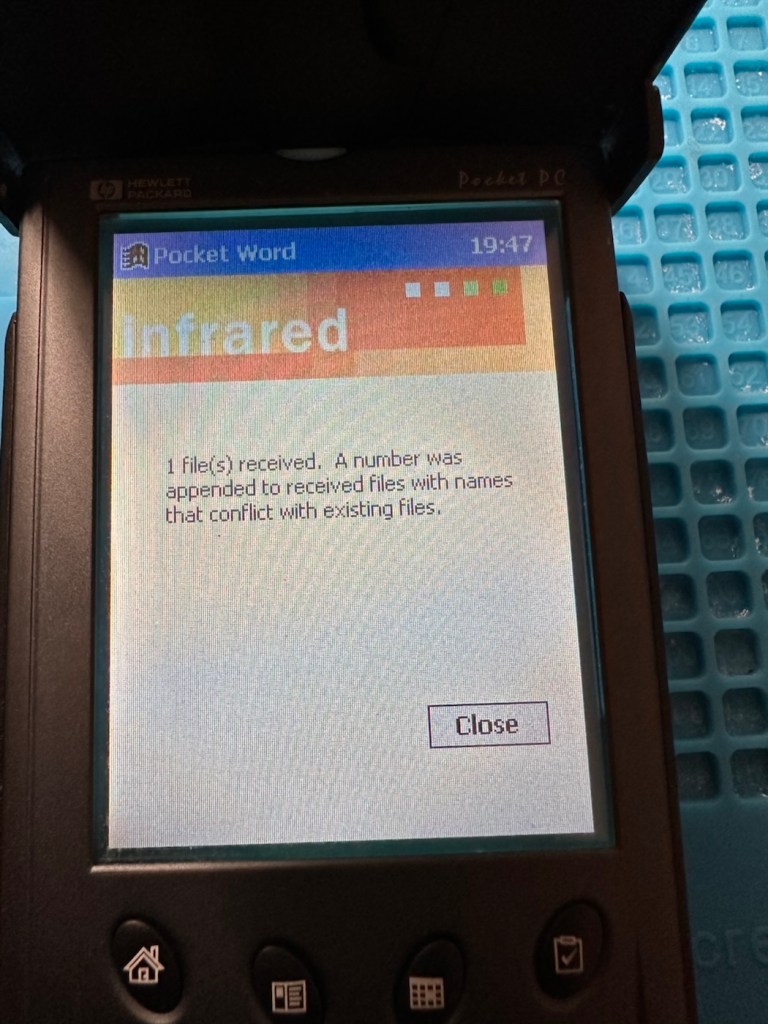
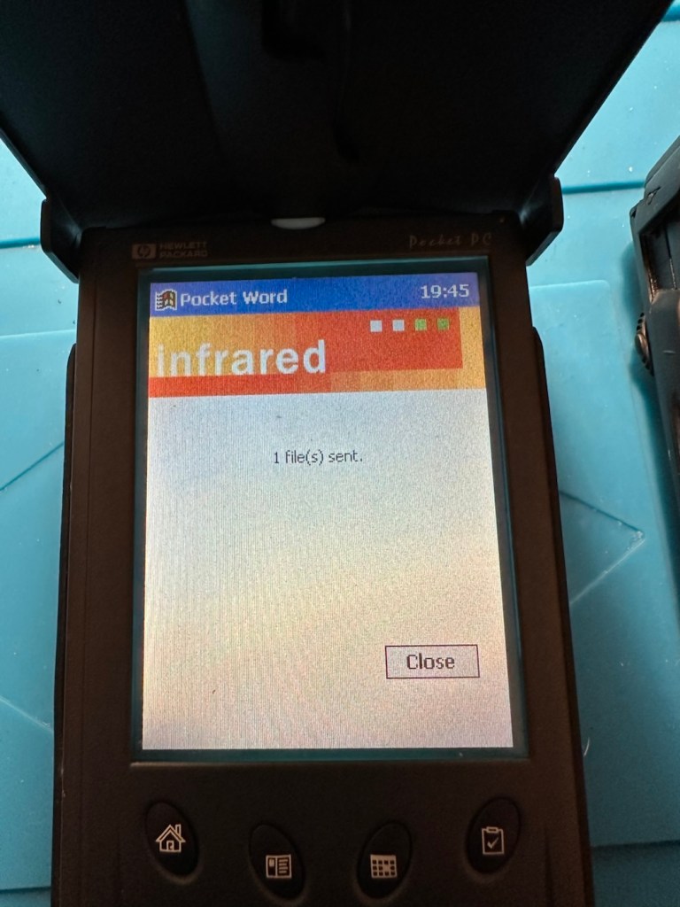
The transfer worked however both units have to be within a very close line of sight to do so, it just shows how much file transferring has moved on within the last 25 years or so. We have been spoilt.

These units are both working fine.

Result:

Full Microsoft CE package
Working as they should be

There are many uses listed for these units online including MP3 players and television controls. However, I think using as a to do list for my workspace is probably the most appropriate usage for me. I need organisation in my life, so what if I’m using technology from quarter of a century ago.

Why not?

Two perfectly good items saved from landfill.

Small victory, and that’s good enough for me.

Many thanks for passing by. It’s always very much appreciated.

Sometimes, but very rarely, “AI” may just work in your favour.

I’m fixing this lens and came across this broken part. But what is it called? Does Chat GPT know the answer? It seems it does.

Please do not for one minute consider this an endorsement for AI, it’s not. I very rarely ever use it, and to be totally honest I keep as far away from it, as i possibly can. The only issue is, is that it gradually sneaks through the back door unannounced in pretty much any application or program that you now use. There is no escaping it really, even here on WP this week I received an invite to start using AI to write my posts and to control their content and SEO compatibility, whatever that is. Straight in the bin it went, no thanks, not interested.

I know my grammar and punctuation leaves a lot to be desired, and sometimes it is very poor, but hey! That’s me and I don’t want to suddenly appear to be a fully functioning and academic genius, as that’s just not me. I’m a Comprehensive educated drop out, that has managed ok thank you, and I don’t need some computer to portray me as something I’m not, or am likely never going to be.

Rant aside, let’s get back to the story that is based around the item in this picture.

What’s that then?

I’m currently carrying out a repair on a Canon EF 28-200 lens from around the year 2000. Whilst dismantling this lens, the above part became the item of interest as this is a piece that controls the zoom of the lens, hence this lens never really worked due to it’s inability to focus or zoom, and the item above appears to be the guilty party.

It’s broken, that is clearly obvious to see, it’s made of an alloy, possibly aluminium, and is not repairable by soldering due to the immense high temperatures that would be required. I can’t achieve such temperatures as I don’t have the equipment available to do such work. I could try forming something from scratch, that is an option but I don’t really have the time or patience to be honest to spend such time on such a tiny piece of metal. The whole piece is no bigger than 2cms long at its longest point. It really is tiny but essential for the smooth operation of this lens.

This is where the AI help comes in.

Having looked at many repair manuals belonging to Canon, I have an immense list of code numbers but nothing at all explaining what this item is or if there are any still available. I’m kind of lost and at odds as to what I should do.

In desperation, I type something similar to this request into Chat GPT:

“Long angular aluminium piece, working the telephoto element of a Canon EF 28-200 lens”

And this came back as an option:

Bingo – Courtest of Barrell Y Store – Ali express

Wow. That looks familiar!

And it is in-fact the part I am looking for, on the Ali Express site, our friends in China have one left in stock – “Click” that’s purchased and is now on its way to me.

I am now also fully aware of what it actually is, apparently it is called a “Zoom guide pillar, zoom lever, electric brush lever for a Canon 28-200 zoom lens”

Well there you go, it appears AI is good at deciphering the ramblings of a frustrated and confused 60 something. And in this case it did very well. When this arrives I’m going to give it to one of the tool makers at work to get him to make a few copies, I’m even going to see if I can get a few printed out 3D wise to see how the plastic version holds out under the demands of the lens. I don’t foresee any real issues as long as the lens isn’t mistreated in any way.

Well. That’s my major frustration of the week, and my first real face to face involvement with AI.

It can only get better, or can it?

Have a super day. Stay real.

Still Haunting

Yep, the Ghost radio service I reported on in August 2025 is still operating in the East Midlands and beyond

Back in August of 2025 I wrote of a radio station I had stumbled across on the DAB network. Ghost radio service.

It’s probably the post that has had the most views on my site, strange! And has been mentioned in numerous chat rooms and sites across the t’internet,

Because no one really knows what the hell it is or who owns it.

Here’s a few definite facts.

  • It can only be heard in the East Midlands, especially around the city of Leicester.
  • It has been heard out in suburban areas on the far outskirts of the city.
  • It is someone making ghostly groans and moans.
  • It is only on DAB networks.
  • No one appears to admit ownership
  • There is very little information on line.
  • 7 months after first being heard it is still active.

And it’s still active today. Here’s a video taken a couple of days back.

Spooky 👻

Digging around, checking the OFCOM site amongst many others, the only new information I can find is listed below:

Key Details About Ghost Service:

  • Content: The station broadcasts a continuous loop of a “ghost” moaning.
  • Origin: It is an avant-garde art project created by a multiplex owner to challenge conventional ideas about broadcast radio and demonstrate the efficiency of their MP2 encoder at low bit rates.
  • Platforms: Initially spotted on DAB (Leicester SSDAB on block 9B and Lubra SSDAB on block 8A), it has also been heard on FM (87.9 MHz) in areas like Billingham and Middlesbrough, sometimes switching to Christmas music.
  • Other Projects: The same entity operates another station on the same multiplexes called “Catalytic Converter,” which plays cat sounds.
  • Visibility: It has garnered attention from local listeners and YouTube creators such as Fox’s Den. 

And it mentions me. How quaint!

Thanks for passing by, have a great day. Thank you 🙏

Rollei XF 35 35mm Rangefinder Film Camera 

I’ve just purchased an old Rollei 35 XF rangefinder from around 1974. It doesn’t work, so let’s see if we can get it working again.

What the listing stated:

The Rollei XF 35 is a compact vintage 35mm rangefinder film camera made in Germany, known for its classic design and portability.

This camera is being sold as spares or repairs and does not power on. It has not been tested with film and is not in working condition; functionality of the shutter, meter, and other features has not been confirmed.

Cosmetically, the camera shows typical signs of age and use, but no major damage is visible. Please note this item is intended for parts or restoration and is not guaranteed to function.

Accessories included: wrist strap and lens cap.

EBay

I like these little point and shoots. I’ve always wanted one, and ideally I would like an original 35, but in the meantime I’ll settle for this one. Not working, only £17:00GBP, this was a bargain price for an old camera with a lens that has a superb reputation for having good optics. It’s a bargain basement price for a camera that has a lot of potential if I can get it working again. I have purchased from this supplier before and they are a good bunch of guys and girls, so I don’t believe I am being ripped off in any way. This camera dates from from around 1974.

Here’s a little bit about this camera:

The Rollei XF35 is a small 35mm full frame Rangefinder camera released by Rollei in 1974. The same camera can be rarely found under the brand Voigtlander: in this case it’s called VF135. 

This camera provides only a programmed exposition, with a CDS cell powered by a small 1,35v PX 625 mercury battery. A ring around the lens must be set to the right ASA/DIN value.

The shutter is a small Copal central type one, that also works on relative aperture.

The lens is a Carl Zeiss Sonnar-derivation, built under license by Rollei. It’s a 40mm f2.3, with focus from 1 meter of distance. The viewfinder has a small frame that indicates the f-stop and the speed of the shutter that the program will use. At the center, two small yellow and red circles must overly to obtain focus on the subject.

Shutter speeds go from 1/30 to 1/650s, including bulb mode (only at f2.3). Copal shutter closes up to f16, so Rollei reccomends max 400 ISO/ASA films.

There’s a hot-shoe flash slot and the camera also includes a self-timer (circa 10s of delay). Under bulb mode, this timer can fire the shutter to a speed of circa 5 seconds.

Camerapedia

I’m expecting the camera shortly, so in the meantime I’m off to read the manual and to also look for replacement batteries that replace the now defunct PX625 batteries this camera used to have to maintain a sufficient power supply. When it arrives we can carry out a full assessment.

Assessment:

On arrival it’s a nice tidy little camera, with slight signs of use and that slight mustiness of being in storage for a few years, though I have smelt worse.

It needs a little clean, the strap buckle is a little rusted however that is easily replaced.

Inside, the camera is clean, the winder works and the exposure button works, however the shutter doesn’t fire. This could be one of a couple of issues, the battery inside that appears to be an original PX625 Mercury battery could be below power, and if it is an original this could well be the case. However the light meter is working and this is a welcome bonus, so there is a little life still in the battery that should be 1.35v when at full power.

Light meter is functioning

Let’s check this with the multimeter, before purchasing a new battery, and I can confirm the battery power sits at 1.53v?

A fully charged 625A battery

I was mistaken, it’s not an original PX625 it’s actually a 625A alkaline replacement. These alkaline batteries are 1.5v rated against the original that was 1.35v. These batteries are commonly used with these older cameras as a suitable alternative to the original battery. The only issues that are sometimes reported are that the metering can sometimes be off by about +2stops, however some people report no issues at all so it is all a little bit and miss to be honest. I guess it’s all down to trial and error with your own film stock and the camera, B&W film would probably be more forgiving. So, in this case it is not a power issue. We need to then move on to another option.

The other related issue could be sticky blades on the shutter mechanism, and that is more than possible if the camera hasn’t been used in quite a while, the old lubricants dry out over time and the shutter blades get stuck, this means I would have to carry out a service of the shutter mechanism, not a major issue just quite time consuming.

Repair:

I have liberally coated the shutter blades from inside with some isopropyl alcohol as that’s all I had available at the time. This has removed some old black gunk that appears to be old oils of some kind, however the shutter still does not operate when activated, even though all the noises are there to suggest the mechanism is actually working.

I have used a compatible tool to tempt the shutter blades open, this initially worked but they did not fall back into place with any urgency. I suspect there is residue on the opposite side of the shutter blades, so it looks as if this will have to be a full CLA – Clean, lubricate and adjust, requiring a partial disassembly of the camera.

Boy I wasn’t wrong, this is probably the deepest I have gone into a camera for quite a while, this camera really does have to be dismantled. These cameras have always been renowned for having issues deep into the cameras workings, it’s probably what has gained them a poor reputation, somewhat unfairly, but not everyone is prepared to dismantle a camera at these prices, when they can just chuck it and get a new one. However that’s not what I do here.

Let’s stop the chat and get on with it.

So we need to get inside, and the best plan of attack is from the front through the lens turret, so first thing we do is remove a retaining ring on the lens. This allows us access to the insert that controls the ASA, and where the CDS cell is located. Remove with caution as there are small wires present.

Three screws under the ASA/CDS module then allow you to remove the focus ring where there is a small brass plate. This is removed and then the rest of the barrel loosens, but cannot be removed….strange.

At this point I had to do a little research and source the maintenance manual and refer to it to see what I had to do next.

Maintenance manual courtesy of Rollei

After reviewing the manual it appears there are another four screws requiring removal before we can access any deeper, however these are situated under the camera “Skin” and this needs to be peeled back slightly to access.

With these four screws removed, you now have to remove both the top and bottom parts of the camera, five more screws to allow the front plate and lens to be removed.

Base of camera removed exposing winder workings

With the lens plate now movable, again I carefully move it aside being wary that there are also wires here, and not a lot of room for manoeuvring. A slight twist of the brass aperture control plate and it can then be removed. The plate below this, with the three brass dots, just clips out and exposes the thin shutter blades below.

Just looking at the shutter blades I can see there is a small link missing, this was sitting loosely to one side, it could have come off as I was dismantling the blades, who knows. Carefully put to one side the blades are placed individually in preparation for a clean. Lastly the bottom plate of the shutter mechanism, lifts out and beyond this point is the camera back, we have just a hole as the whole shutter and lens mechanism has now been removed.

All parts removed have now been cleaned with an IPA solution to remove any grease and dirt, and there was quite a lot of both. These have all been put to one side and will be cleaned once more prior to reassembly.

A period of time was spent just watching and observing whilst I continued to prime the camera and fire the mechanism to see if I could see anything obvious that was of concern. After a while I could see the issue, there is a small flywheel that was not moving, and as a result the connected shutter mechanism could not move.

The flywheel controls two parts of this mechanism. Firstly the shutter mechanism to move and work the shutter blades, and secondly there is a small brass pin at the top that also moves relative to the aperture setting, if this is in the wrong position, the shutter fires but will not close, this wheel is where the issue lies.

Using some IPA I get into the gearing from the base area, and give all the gears that I can access a good clean, I activate the camera numerous times to get as much grease and dirt away from the workings as possible.

Then using a very fine camera oil, very sparingly, literally a drop on top of a needle applicator, I place oil onto the cogs paying special attention to the offending fly wheel.

I have three shutter blades that are super thin and delicate that need a final clean, dry and a dry wipe prior to reinstalling. I get this done and then put both links in place, after installing the blades in the correct order.

Shutter blade reinstalled, with both links
A small video showing the shutter working

The re installation of all other parts is just a reverse action of how they were taken out, each part was cleaned as it was put back, so in theory the camera is an awful lot cleaner and free of contamination than it was a while ago. Before I put the lens plate back on the camera I check the shutter’s operation and it is all fine. Just a final calibration of the aperture settings, a check of the focus range, and just ensuring all wires are routed sufficiently, and the lens plate is ready to attach to the rest of the camera. This done, the base and top fascia plates are attached after first cleaning the focus window and light meter window. The camera is now fully assembled, it now just needs the camera “Skin” to be re glued where it was earlier removed for access.

Reassembled and just needs gluing

The skin is now glued into place.

Now I’m outside the camera I’m just going to touch up some of the scuffed areas with some permanent marker, it’s not worth stripping down, priming and repainting, to be honest I’m quite happy just doing a touch up of the scuffed areas and that is what I have done. Once it gets a clean and polish it will appear much improved, compared to when the pen is first applied, it will blend in.

Before and after pen applications

I’ve taken the old strap buckle off as that was rusted, I’ve just used the original strap ring to connect to the camera lug, I think it looks good. I’ve also added a cover for the hot shoe connector that I’ve printed off on the 3D printer.

Original ring

And that completes the repair, the last thing to do is get this camera cleaned and polished.

Result:

With a good clean and polish, this little handheld has come up looking superb.

With all the extra touches, we now have a superb working, resurrected camera that was heading for landfill. This has taken a lot of time and patience, something I don’t have a great deal of if I’m honest, but I was determined to get this project finished. And it is. It looks good, works good and has years of life left in it. Currently sitting at 52 years old, it has a long life ahead of it.

This camera probably rates as one of the most fulfilling and pleasing projects I have ever started upon and completed. It’s been a very delicate and time consuming job, and that I will not deny. It’s only a cheap low cost camera but it’s taught me a great deal. It’s the first complex project I have undertaken, in my new workspace, I don’t think I would have been able to complete it with my old set up. It’s been an achievement, one I am considerably proud of, an occasion when once again, it doesn’t matter how old you are, you can still learn a lot. A big positive for me.

Anyway, enough about me.

Thank you most sincerely for passing by and giving me your time. It really is, very much appreciated.

Return of the Osprey

Every year the Ospreys return to Rutland water in the East Midlands. Here’s a live link to their nest in Manton Bay. Enjoy!

We are quite spoiled up here in the East Midlands with some stunning scenery as well as a plentiful array of stunning wildlife.

The Osprey

One of the most interesting projects in place for the last 10 years or so is Rutland Waters work to encourage the breeding of the Osprey. The project is run by the Leicestershire and Rutland wildlife trust and a link to the work they do to look after these stunning birds can be found here: Rutland Ospreys.

The live view of the Osprey nest

This live feed above covers a nest site on the Manton Bay Area of Rutland water. its current residents, a female called “Maya” and her other half known as “33” (His leg tag number) arrived about a week or so ago and are busy, fishing, nest building and mating. (What a life eh?)

Here’s a little history about these two resident birds, courtesy of the Leicestershire and Rutland wildlife trust website:

The Osprey nest in Manton Bay has been in use since 2007, but has been occupied since 2010 by the same female bird, presumably from Scotland, which we have nicknamed ‘Maya’.

Maya arrived in the summer of 2009, and spent the summer bonding with a Rutland-fledged male Osprey, 32(05). The pair did not breed, but both returned in 2010. Unfortunately, in 2010 two male Ospreys went missing from Rutland, and 32(05) was one of them. However, she managed to pair up with a male Osprey, 5R(04) which was holding territory at the Manton Bay nest, and they successfully raised three chicks in 2010. At the time, Maya did not have a name and she was always referred to as the Manton Bay Female. Over the next few seasons, it was decided it would be easier to talk and write about her, and for people to relate to her if she had a name, and eventually we settled on Maya. Not only is it a lovely name, but it contains the first and last two letters in Manton Bay, and comes from the Greek Maia, who was the goddess of spring.

Over the three years (2010 to 2013) that Maya and 5R(04) bred together, they successfully raised 11 chicks. Of those 11 chicks, five of their young have since returned to Rutland! 

In 2014, unfortunately, 5R(04) failed to return to Rutland after his migration. After weeks of anxious waiting, we came to realise, as did Maya that he was not going to come back. Ospreys face many challenges on migration, so sadly, we won’t ever know what happened. With plenty of unpaired males in the area, Maya paired up with male 28(10) and did actually lay three eggs. But the nest suffered persistent intrusions from 33(11), and as a result, 28(10) was chased off and 33(11) took over the nest, kicking the eggs out in the process. After a while 33(11) and Maya did form a bond, but it was too late in the season for them to breed.

As we see Maya every day on the live webcam, we have come to know her very well as an individual. All Ospreys have unique, distinguishing characteristics, and Maya can easily be identified by the distinct markings on her head and face, in particular the brown cross that is visible on the back of her head. She has now raised 31 chicks since she first bred in 2010 and has provided us with a fabulous insight into the lives of breeding Ospreys.

33(11) fledged from one of the offsite nests in 2011 and his parents are male 03(97) and an unringed female. 33(11) was the only chick to fledge from that nest that year, so he did not have to compete for food, consequently becoming a strong, healthy juvenile and adult. 

33(11) returned to Rutland for the first time as a two-year-old on 11th May 2013. He was first spotted in Manton Bay, by Project Officer Paul Stammers and volunteer Mick Lewin, then later was seen back at his natal nest, Site B. In 2014, he returned on 13th April and immediately began pestering Maya and 28(10) in Manton Bay. He did not give up until he chased 28(10) away and claimed the nest.

In 2015, both Maya and 33(11) returned to Manton Bay and bred successfully, raising three chicks, two of which have returned. 33(11) appears to enjoy spending time on the nest, more so than other males and will quite often take over incubation duties. Since 2016, they have raised an additional 24 chicks, including a record breaking four chicks in 2019 and 2020!

Courtesy: Leicestershire and Rutland wildlife trust

So there it is. Pay a visit and watch a couple of the world’s most beautiful birds in one of the most beautiful and scenic wetland areas of the East Midlands.

Thanks for passing by. It’s always appreciated.

Ilford Sportsman 35mm camera

I’ve been asked to give a little service to a friends old 35mm camera that he’s inherited. Mainly cleaning and making good. An old camera that deserves to maintain its originality.

I received this text message tonight from my nephew:

Hi, my mate “T”, has got an old camera from his sister, from a old antique store, he dunno a lot about it and was wondering if you did and if you’d have a look at it and see if it was in working order as he can’t figure much out about it, no worries if not tho 👍

Family

Now, I love these random out of the blue messages, to me it just says people have a trust in what I do, and I like that. And how can I turn down a request such as this. I’ve jumped on to it and said I’d give it a service and get it checked over and up and running, no cost, I just want to feature it within my blog site. The owner is also a youngster, just starting out in photography and has a thirst for knowledge of the traditional side of business, and wants to find out more about the old ways and how the trade used to operate. He wants to shoot film, and process it, and produce his own prints. I can help him do that. And I look forward to passing that knowledge on. In the meantime, this is the camera we are looking at, and wouldn’t it be just great to get it working and use it to get those results under tuition, that he wants to achieve.

This camera is really a rebadged Dacora Dignette produced in Western Germany for Ilford Uk.

Here’s a little history regarding the Ilford Sportsman camera range:

As the desire to own a 35mm camera blossomed within popular amateur photography during the latter 1950s, in part prompted by the more economical production of projectable colour transparencies on 35mm instead of roll film, Ilford Ltd must have been concerned that they did not have their own range of such cameras.

Kodak was importing their 35mm Retina/Retinette range from Kodak A.G. in Stuttgart, a factory they purchased in 1931, (originally the Nagel Camerawerks).

To provide a suitable ‘popularly priced’ 35mm camera, Ilford entered into an agreement with Herr Dangelmaier of the Dacora Kamerawerk, Reutlingen, near Stuttgart, (West) Germany. Dacora produced a simple 35mm camera, the Dacora Dignette, but rebadged it as an Ilford Sportsman for sale in the UK.

Ilford’s Sportsman cameras were a range of viewfinder- and rangefinder-cameras, made for Ilford in Germany by Dacora; the first was introduced in 1957. They were a cheaper alternative to the Kodak Retina and Retinette series for the newly-popular 35mm format at the time. The Sportsman cameras were rebadged versions of Dacora models, including the Dacora Dignette. There were a variety of shutters fitted, including Vario and Prontor mechanisms, housing a selection of lenses such as the Dacora Dignar, Steinheil Cassar and Isco Color-Isconar. The range included basic models, with the Vario shutter and Dacora lens, through fitted meters to sophisticated rangefinder cameras with light meter, Prontor 500LK shutter and Cassar lens.

There were five body styles; the last (Mk.5) introduced c.1967.

Wikipedia/photomemorabilia.co.uk

This version dates from 1957 and is one of the later issued Mk1 versions of that year. It has the Vario shutter mechanism and the Dacora-Dignar lens. The badging indicates that this is a latter 1957 produced variant. The very early versions had the “Ilford” badge printed on the camera leatherette and I suspect this would have rubbed off due to hand positioning whilst photos were being taken. This is probably why the white badge on this variant was then applied. This camera retailed in 1957 at the princely sum of £13.87GBP.

I am now in possession of the original instructions that I will download and pass on to the owner, they are extremely basic instructions, befitting of the year of production.

Front page of instruction manual

Assessment:

The camera is in an overall good condition in an original Ilford leather case and I think this alone has helped keep the camera in good cosmetic condition. It winds fine, it shoots with a little bit of stickiness, but I believe this is on the exposure button only. The aperture leaves stick a little and respond slowly when you leave the shutter on a time exposure and move it through the whole range from f:3.5 to f:16. The focus ring seems to operate smoothly, and shutter speeds of B, 25, 50 and 200 seem to work, but occasionally stick. I suspect the shutter and its aperture leafs are dirty and are sticking, they probably need a clean.

Now I’m not going to do too much to this camera and want it to retain its old character. The leatherette on a couple of parts of the body has lifted, I will probably leave this as it is, I will dismantle the lens turret as there is a general fog in the lens that I suspect may be fungus. I will give the whole unit a good clean and polish. There is a slight break in the leather strap, I shall repair this so as it doesn’t break. There really is nothing of concern that I can see that should be of detriment to the working of this camera. It just needs a clean, and that’s what it will get as I really want to maintain the character of this camera.

Repair:

To get to the lens and shutter area we have to start dismantling the lens turret, that starts with removing four of the tiniest screws you will ever find.

We now unscrew the first element, the outer one, and it’s clear to see that there is fungal scarring of the element.

Fungal scarring evident

Next we unscrew the next part of the lens barrel that gives me access to the inner lens element.

We can now reach in and delicately remove the inner element

Removal of the inner element

We now expose the shutter blades and underneath these we find the aperture blades.

I start by giving these sections a clean with a a little “lighter fuel” to remove the old grease and oily deposits. With the shutter blades I clean them very carefully, let them dry a little and then fire the shutter a few times, I blow off any build up and do the process again until I’m satisfied they are free from any contaminants. Now putting the shutter on “B” setting, I open the lens and do the same with the aperture blades opening and closing them manually using the same process as with the shutter blades. Happy with how this has gone I now head onto the elements.

Using a mix of pure water and peroxide I use a small bud to coat both sides of the inner element to give it a clean, it is very dirty, no fungus on this element though, just years of dirt and grime.

Inner element was very dirty

The outer element was a different story, it had such bad fungus that the edges of the element had been etched by the fungus, as it had been there so long. I don’t think it will be too much of an issue through as a lot of it was removed. Below are two photos before and after, the after looks quite a bit better and when it was dried and polished it did look considerably better.

Once cleaned I rinsed the elements off and dried them using a lint free cloth. A good blow with some air dispersed any loose dust or fluff, prior to reassembly.

Reassembly was simple and without issue, I cleaned as I went along replacing any grease and oil with fresh lubricant (sparingly of course).

Reassembled and ready for cleaning

Cleaning wise I’ve used IPA, detailing polish, cocktail sticks (to get into the nooks and crannies) and good old elbow grease. It’s looking good.

Leather strap repair

I’ve repaired the broken strap by just removing the damaged part and creating a new strap loop, it looks ok, but I’m working with a strap that’s almost 69 years old, very thin, and has seen better days, but it looks okay. There are loose bits on the case where the leather stitching has deteriorated, however leather work is not my forte, so I will be leaving this alone, letting it maintain its old appearance and patina if you like.

Result:

The result is that I have been able to maintain the original appearance of this camera, only carrying out a sympathetic maintenance regime, allowing the camera to be used as it should, but maintaining its age and individual characteristics.

That case with repaired strap

It’s been nice to just tidy up a camera and give it some attention, TLC if you like. These cameras are remarkably easy to maintain and operate, I’m sure a roll of film through it will give some superb results. The viewfinder is so clear now, the lens is clean and the shutter, aperture, and all buttons and levers are working just fine. It’s been a pleasure to work on this camera, and I sincerely hope that my friend is happy with the outcome. One thing you really struggle with though is the old musty smells these cameras carry with them. If I had a solution I could use to negate these aromas I’d probably be a rich man, or at least my wife would probably forgive for once, for bringing these aromas into the house.

Oh well, you can’t win them all.

Thank you for passing by, it’s always very much appreciated.

Sums up my current state of mind….perfectly 😂

Saw this online. Made me laugh out loud…

I saw this online today and it did make me giggle. And my wife is in full agreement with this statement.

Have a super day 👍

Canon Snappy 50 automatic 35mm camera

A compact Canon 35mm camera from 1982. It doesn’t work, so let’s make it work!

What the listing stated:

In generally good condition but does not power up
Sold as spares or repair

EBay

I came across one of these a few weeks back and was just taken by the shape and aesthetics of it. However i wasn’t going to pay a high price demanded by the seller, so i just hung around and waited for others to come on the market. I have just purchased this camera with free postage for a total of £1:13GBP. I’m confused, the seller will basically be paying me to take it off his hands as postage will be at least twice the value of what I have paid today. Let’s wait and see if this sale gets suddenly cancelled, as I suspect it may well do.

Anyway here’s a little bit of its history:

Released in July 1982 and based on a new concept, this is a fully automatic 35mm Lens-Shutter compact camera.

The camera height was reduced by about 30 percent, giving the camera an oblong and unique form.

The camera uses active autofocus with a solid-state near-infrared beam. EE and the aperture are controlled electronically with a program. Metering range is EV 8.6 (f/3.5 at 1/30 sec.) to EV 15 (f/9.5 at 1/350 sec.). The shutter speed is set within a range of 1/20 sec. to 1/500 sec. to suit the film speed.

There is only two film speed settings. ISO/ASA of 100 or 400.

The built-in flash (Guide No. 11 at ISO 100 in m) must be turned on manually with a switch when the camera-shake warning lamp lights in the viewfinder.

Canon

I’ll just wait now to see if it turns up. I don’t know what the problem with it is, it’s just listed as a power up problem.

Well I’m shocked, I’ve received a postage notification so it is definitely on its way. Next stop…Assessment.

Assessment:

Well, it arrived, I’m shocked. It’s got to be one of the best packaged items I’ve ever received, never have I seen so much bubble wrap protecting an item that cost just £1:13GBP.

On top of that the sender has spent £3:45GBP on postage and charged me nothing. God I feel guilty now, least I can do is give him some glowing feedback.

Wow – And I paid nothing

Right, back to the camera. For a 44 year old camera it really is in beautiful cosmetic condition and needs nothing but a slight dusting to finish it off. But first I put in two AA batteries and can confirm it is dead. No life at all. Also, the film door is flapping about (So there was another issue!). I’m going to have to get inside this unit to see what is wrong. To be honest the unit is such a basic one, I suspect there isn’t a lot that can go wrong with it.

Repair:

The film door issue is a simple one, and if I didn’t have a ton of spare parts spread around the place, I’d be quite annoyed to say the least. It would have been either a case of making a new catch for the door or building some Heath Robinson contraption to secure the door, looking completely out of place. However, I just so happen to have a complete rear door for one of these cameras so hopefully it should be a simple swap out of parts.

But before I do this simple replacement, I need to get the top and bottom off of the camera to check where the electrical issues lie.

Taking the bottom off of the camera, the problem presents itself quite clearly. At the bottom of the battery chamber the negative wire has detached and needs soldering back into place.

Negative wore detached from battery chamber

I put the base back on and put two batteries into the chamber and the rewind motor instantly kicks in. We now have power. The shutter works and the winder motor operates as it should. When the rewind button is depressed the rewind motor kicks in as well, all seems to be good…..until!

The live supply to the flash was detached

I try the flash, and nothing. Not even the usual sound of the flash capacitor charging. Damn, I hope that capacitor isn’t dead! So now I have the top off of the camera and another problem presents itself just as clearly as the first. Not a problem here as I need the top off to replace the rear door.

Rear door hinge removed and replaced

The live supply to the flash had broken loose and this also needed re soldering, in fact I re soldered about eight wires in total as it seemed that the solder joints in these critical areas could possibly be fairly. They may not be failing, but whilst I’m inside why not just do this simple task to prevent anymore premature failings?

Batteries back in, flash turned on (it’s manual on this camera) and the check light illuminates. This camera is now fully operational.

Flash check light now illuminates

Result:

I’ve had a fairly simple repair here with some soldering and luckily, some spare parts available. These cameras are quite tricky to repair due to their compact build. Normally when you detach one part you have tiny springs and other parts that fly out, leaving you with a head scratching puzzle to add to your issues. However having dealt with these cameras in the past and having learned my lesson previously, I was very careful and took my time ensuring nothing occurred that would cause me any issues further along in this fix. I also open these cameras in a box, so if anything does fly out, it doesn’t fall onto a carpet disappearing into the pile, it just falls into the box, saving me the embarrassment of looking for a tiny piece of camera, that could be just about anywhere on the floor of that room. You learn from previous mistakes, I have, and i now have procedures in place to prevent such issues happening again.

All cleaned up and working
And neatly cased

We now have a lovely example of compact 35mm photography, rejuvenated, repaired and ready to get back to doing what it was designed for, creating memories.

And long may that last, another one saved from landfill, repaired, recycled and now with many more years of purpose.

Many thanks for passing by 🙏

PS5 DualSense controllers

When the youngsters of the clan, drop surprise repairs on you at family gatherings.

It’s great when one of the youngsters of the clan come up to you at a family gathering and greet you thus, “Oi, uncle Dave, have a look at this for us will you?” and then they just disappear into the crowd as I’m now holding a couple of items I’ve never been exposed to before, in this instance a pair of Playstation 5 Dual sense controllers. (I had to google to find out what they were!)

Here you go “Uncle Dave”

Apparently they don’t work, or are having difficulties, and it’s now down to me to find out what’s wrong.

Now I’m not a gamer in the true sense of the word. I like, and have repaired and own a good few hand held devices that have been featured within these blog pages, but I do not own a console, I never have. However I’m lucky in that I know a few people who do have these consoles, who I can go to and test how they are behaving, but the good thing is that these controllers can also be tested without a games console and just require a computer with a USB port, and I do have one of them, a clever move by the manufacturer me thinks.

First thing I did here was to plug them in to a USB supply to charge the onboard battery. Each one has a 3.7v rechargeable battery that should give between 6-12 hrs of activity depending on how vigorously the unit is being used. When charging it glows on and off orange until it is charged and then the glowing just stops. Both these units took about 2.5 hrs to fully charge, and they seem to both be holding a good charge seeing one of them, the black version has not been used for some time.

Let’s get them connected up to a PC.

A simple good quality USB cable is the communication method between the controller and the PC. Next, you go to the address: https://dualshock-tools.github.io and here is where you will be doing those checks on the controller that sits in your hand. Seeing I don’t really know what’s wrong with the controllers I have been trusted with, I think this is the best place for me to start my investigation as the site does do some good, and thorough testing.

I have two controllers to check so I start by plugging in the Black controller, clicking connect on the screen gets access into the memory of your controller and all the firmware detail and build date is displayed in front of you. Cool!

Just under where this information is displayed we enter the first series of tests, a bank of 8 basic function tests that check all bells and whistles (as such) are operating as they should. This Black controller passed all these tests with flying colours.

All 8 checks passed

The checks are thus:

  • USB controller: here the connection is tested a simple pass or fail
  • Buttons: all buttons have to be continually pressed until they turn green on the screen, a simple pass or fail
  • Adaptive trigger: the system puts a resistance on the two triggers representing various triggers on guns and switches experienced in various games, if there is suitable resistance here the result is a pass.
  • Haptic Vibration: this tests the vibration motors in the controller, if it’s working then it’s a pass
  • Lights: all lights on the controller are cycled through displaying the whole range. Simple pass or fail
  • Speaker: a tone is played through the built in speaker, a simple pass or fail.
  • Headphone jack: a simple test of the plugin headphone jack – pass or fail
  • Microphone: a simple test by blowing in the on board microphone checks if it’s working, a simple pass or fail.

And as stated the first controller, the black one has passed all of these tests. Impressive. The next tests are all centred around the two thumb pads, their return to centre position and their all around circular motion and their calibration.

The left pad was showing slightly off centre and I was able to make some minor adjustments via the program interface to correct this issue. The good news was that it is not a constant stick drift, and the mechanism does not require replacement, it is easily adjusted. With settings saved, disconnect the controller, reinstall it and re check the calibration and it should all be good. And it was. With minor adjustments made to this controller I am pleased to say it is working as it should, it is now repaired and will be heading back to its owner.

Now onto the second item, the white controller. I put this controller through the exact same testing protocol as the first one, all was going well until we got to the buttons section where this one failed. The down button on the left hand side of the controller is unresponsive, you can see this in the photos below

Failed test in the button section
Failed button highlighted on Controller and screen

All other tests on this controller were fine. Again there was a little drift on the sticks that I was able to adjust and they are now both as central as they can be, operating well through their whole range. I will go through the repair and retesting of this pad in the section below the YouTube video that I have highlighted below.

A while ago, if your game pad was playing up, there wasn’t really a great deal you could do apart from replace the thumb controllers if you were experiencing issues such as a little stick drift (when a controller is moving on its own accord). A bad case of stick drift would require you to change the controller mechanism. However, some very intelligent people within the gaming community have put together a number of packages to test your game controllers, but the one mentioned in the video below has been a game changer as such, as it also allows adjustments to be made and saved and thus extending the life span of the components within, thus reducing the need to replace and dispose of those components prematurely. Have a look, it explains the testing protocols and checks them against other programs.

The whole testing procedure checked and compared with other testing programs

Repair and retest

It’s a simple enough activity to get inside of the controller, some clips, and four screws get you inside the package, getting beyond this though to the controller buttons where we need to be is a little bit more in depth. So here we go…

I’ve dismantled the controller as I said I would, initially the process requires four screws removing, after you first gently prise off the black decorative plastic surround as in the pictures below.

When you remove these screws the next task is to gently prise the two shells apart that then reveal the base of the controller

Shell successfully removed

At this point the battery needs to be removed and that is a simple plug disconnection, the battery plate has a single screw in it that needs removing. Before you remove the battery plate there are four ribbon cables that need removing, if you don’t do these then you will probably tear them and need to replace them. Believe me, I have done this in the past and ruined the tiny microphone ribbon at the very front. It’s not expensive to repair, just an unnecessary expense. Don’t rush it. Another 3 screws removed and we can now take off the top cover and get to where we need to be.

Top removed exposing fault pad area to the left

As soon as the top was removed I could see the potential issue with the controller direction pads. The pads are a rubber base with a carbon pad that makes contact with the circuit board below. Sometimes a simple clean of these pads can be sufficient to regain a connection between the two, but in this case it was plain to see that the pads on both sides were both well worn and to be honest they both required replacement.

Normally a good clean with IPA will work

As stated I did give a clean to all contact points with a solution of IPA, reassembled and tested again with no change in performance, the fault remained. I will now need to purchase a new pad assembly and replace the film circuit board below them. Fortunately these are freely available and will cost no more than £6:60GBP to replace. And considering a new controller would cost at least £60:00GBP it’s worth the small investment to restore it.

I now just have to wait to receive these items and get them installed.

The items arrived just as in the photos above, and following the previous instructions to dismantle the unit, I have removed the old conductive film sheet and replaced this with the new one. I have also removed the silicone pads with the carbon inserts and these have also been replaced.

Now all I have to do once I have connected the ribbon cables is to get the outer shell back on the controller. Once this is done, I can log in and start the testing process once again, connect the controller to it and then commence a full test of its functionality.

And as you can see in the above photographs, this has been a successful outcome. Where the left hand side lower button had failed, the new conductive film has addressed the issue and this handset now has full functionality and is working as it should be.

Next I’m just going to do a re-calibration, to check that the sticks haven’t drifted in anyway. If we are in a good position, we can then class this repair as successful and then it can then be passed back to my nephew to carry on shooting aliens, and he can then continue his mission to save the world.

Result:

Two controllers have now been serviced and are both working well and within tolerance. They are about to be returned their owner so he can get them back into use, killing aliens and saving the world from a zombie apocalypse (or whatever he does with them)

Not having a lot of experience prior to receiving these two controllers, I was a little doubtful about where to start and what to check. However after reading up on them, and their operation, I was able to pick up a lot of advice and information regarding their manufacture and serviceability. I like to think that I’m well clued up on these items now as I can disassemble one in minutes, replace parts and reassemble without having any screws or parts left over ( Always a good sign 👍)

And to round things off I have now been given one of his friends controllers to repair as well, so I must be doing something right!

Thanks for passing by, as always it’s always very much appreciated.

Packard Bell DB128 personal organiser

Another personal organiser / PDA from 1992. The Packard Bell DB128. Does it work? Is it just needing new batteries? Who knows? Let’s have a look.

What the listing stated:

The Vintage Packard Bell DB128 Deluxe PDA Personal Organiser from 1992 is a charming piece of retro computing history. Manufactured by Packard Bell in China, this personal organiser is a single unit that serves as a reminder of the technology of the early 90s. With its vintage appeal, this item is ideal for collectors of vintage computing devices or those who appreciate the nostalgia of older electronics. The Packard Bell DB128 Deluxe PDA is a unique and rare find for those curious about the evolution of personal digital assistants. Needs new batteries at the very least. For repair or spares only

EBay

I love these postings on the selling sites, no actual real description of the state and condition of the unit you are purchasing, only a potted history of the item with the standard EBay get out excuse of “For repairs or spares only” I know, I can hear you saying, “ Well don’t buy it then – fool” and I agree with you wholeheartedly, I am a fool and I’ve brought it. But, it only cost me £3:30GBP so I’m happy with that, a good price for a bit of retro tech from 1992.

There is a good chance that this unit does only need some power, wouldn’t that be good? However it wouldn’t make very good copy on a site that looks at fixing other peoples castoffs, but I can happily go with the odd quick fix once in a while.

I love these old PDA devices from the 90s, and lots of people do, I guess some of us are still stuck in a period where technology was so wonderfully new and interestingly different. Whereas today everything is pretty much the same and controlled by a few massive organisations, when back in the 90s there were lots of different companies for you to choose your wears from.

I’ve certainly worked on a few on this site, just check the links on the home page to see what I have worked with.

If you are interested in the 90s PDA technology, may I suggest you look at this guys YouTube site. His name is Hugh and his channel is called Handheld Computing and he is a very interesting chap, and the technology is superb. Give him a visit.

Ok. Let’s read a little bit more about this unit:

The Packard Bell DB128 (also known as the DB-128 or DB 1280 IR) is a vintage handheld personal organiser released in 1992. Also known as the Oregon Scientific DB-388P. It was designed as a compact digital databank to store contacts, manage schedules, and perform basic calculations. 

Technical Specifications

The device features the following hardware details:

  • Memory: 128 KB total memory, with a user-available area of 131,070 bytes.
  • Display: An 8-line by 32-character dot-matrix screen.
  • Power: Operates on two or three CR-2025 or CR2032 button cell batteries, often with an additional battery for memory backup.
  • Physical Dimensions: Approximately 15.8 x 8.2 x 2.3 cm, weighing about 252g.
  • Connectivity: Data can be synchronised with a PC via a serial cable or infrared (IR) LEDs. 

Core Functions

The DB128 includes several built-in applications for daily organisation: 

  • Phone Book: Stores multiple contact categories including names, fax, mobile, and email addresses.
  • Scheduler: Features a calendar and appointment system with start/end times and audible or silent alarms.
  • Utility Tools: Includes a 12-digit calculator, home and world clocks, currency/metric converters, and a memo/expense tracker.
  • Security: Offers a password protection feature for sensitive data. 

Google

I just have to wait for its arrival now and I’m looking forward to that, I won’t speculate anymore about what might be, I best just wait for its arrival to carry out a suitable assessment.

Assessment:

It’s arrived and good god, it looks as if it’s been stored in a vacuum cleaner bag 🤦‍♂️ it’s utterly filthy, funny how none of the original photos showed this isn’t it? I don’t believe this is the same unit as was in the original posting.

If I’d have taken this into the house with the wife present, i think she’d have murdered me, or at least severely injured me one way or another… So that is why you will see that these pictures were taken at the kitchen sink, the first thing this unit received was a clean with a cloth and warm water. After that it’s had a good polish and it is now nice and clean. Now it can come further into the house, into my domain!

Before and after over the kitchen sink

Now the unit is tidy, everything is as it should be, and the screen is in a good condition barring a few minor age related scuffs. It’s dead, and that’s to be expected, I’m just hoping there are no major surprises awaiting me when I get the back off to have a check inside.

Three screws later and the back is off. All three batteries are still in place, all very dead but fortunately there is no corrosion or battery leakage. All that is visible is some age related tarnishing of the battery enclosure, this however has no effect on the board or electronics and will tidy up with a little brush over with some relevant cleaning solution.

With these little database units you were always supposed to change the two main batteries and get them in place before even considering removal of the single back up battery. This was purely to ensure that saved data was not erased from the memory bank, however as all these batteries are dead, it’s no real issue here. The backup battery is protected with a single screw that needs to be removed to allow access. This unit was able to transmit and receive data using infrared technology. If you look at the picture above with the case off, on the left and the right of the chassis you will see a white diode component, these are the infrared transmitter and receiver parts of the data transfer circuit.

The batteries needed within this unit are CR2025 mini cell batteries, I currently only have CR2032 batteries, they look the same but just what is the difference? Thanks for asking, i will now explain.

  • The letter “C” refers to the batteries chemical compound, “Lithium” or to be absolutely precise “Lithium Manganese Dioxide”.
  • The letter “R” refers to the battery shape, in this case its “Round”.
  • The numbers “20” refer to its diameter in millimetres in this case “20mm”.
  • The numbers “25 or 32” refer to the “Height or Thickness” of the battery in millimetres “2.5 or 3.2”

And there endeth the lesson for today. So, in all aspects the batteries are exactly the same, 3 volts, but there is just a slight variation of 7/10 of a mm in thickness. In some cases this is not an issue where there might be that slight bit of space for you to use an alternative cell, however in the case where tolerances are tight such as in watch mechanisms, that tiny difference in size may not allow you to reassemble the backplate to the watch. I hope that clears up the difference between the two coin cell letter and number allocations.

I can use CR2032 batteries in this unit as there is the space. I have some CR2025 batteries on order, so I will comply with the original standard when they arrive. But for the purpose of testing further, the CR2032 batteries will suffice.

Repair:

What repair, to be honest it’s been more of a clean, I’ve cleaned the inside circuit board with some IPA and a brush and cleaned all the crevices with a pick and finished off the outer case with a good coat of antiseptic cleaner and polish. I have inserted the three required batteries and switched the unit on.

Not a great deal more I can say. It’s clean, in fact it’s very clean, and fully functional.

Result:

It’s 34 years old, it’s been discarded, put aside for disposal, given one last chance in its chequered life and I purchased it for £3:30GBP. It’s now revitalised, cleaned inside and out and been given a new lease of life. One of those very simple clean and repairs that anyone can do. And another item is saved from landfill.

When turned off
When turned on

This will now be added to my ever growing collection of old PDA equipment from the 90s, a collection that is starting to grow at quite a considerable rate. I have a few more little projects similar to this in the pipeline, quite similar to this one but requiring quite a bit more attention. Please keep passing by to keep up to date with these “mini” projects.

Once again, thank you for passing by, it is always very much appreciated.