
PT109 wooden torpedo boat kit – finishing

This article covers the completion of the build of this beginner’s kit that can be found here: PT109 wooden torpedo boat kit – construction

This post covers the finishing, that is the priming, painting and installation of the radio gear to complete the build of this wooden model boat.

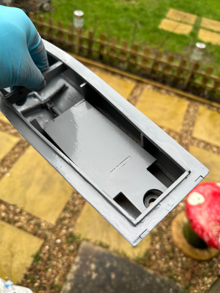
I have to give a couple of coats of high build primer to the hull and deck sections, and for this task I will be using Guild lane high build primer.

This will seal the already sand sealed wood and give it a good foundation for the final paint application. I will give a good initial coat, lightly sand and fill any imperfections and then give a final second coat prior to choosing the colour scheme I’d like for this boat.

Today I have given the first two coats of primer to the hull and deck, and I’ve primed all of the cabins and guns and torpedos in preparation of individually painting them. I need to do a light sand on the hull and I believe a third coat will then suffice.

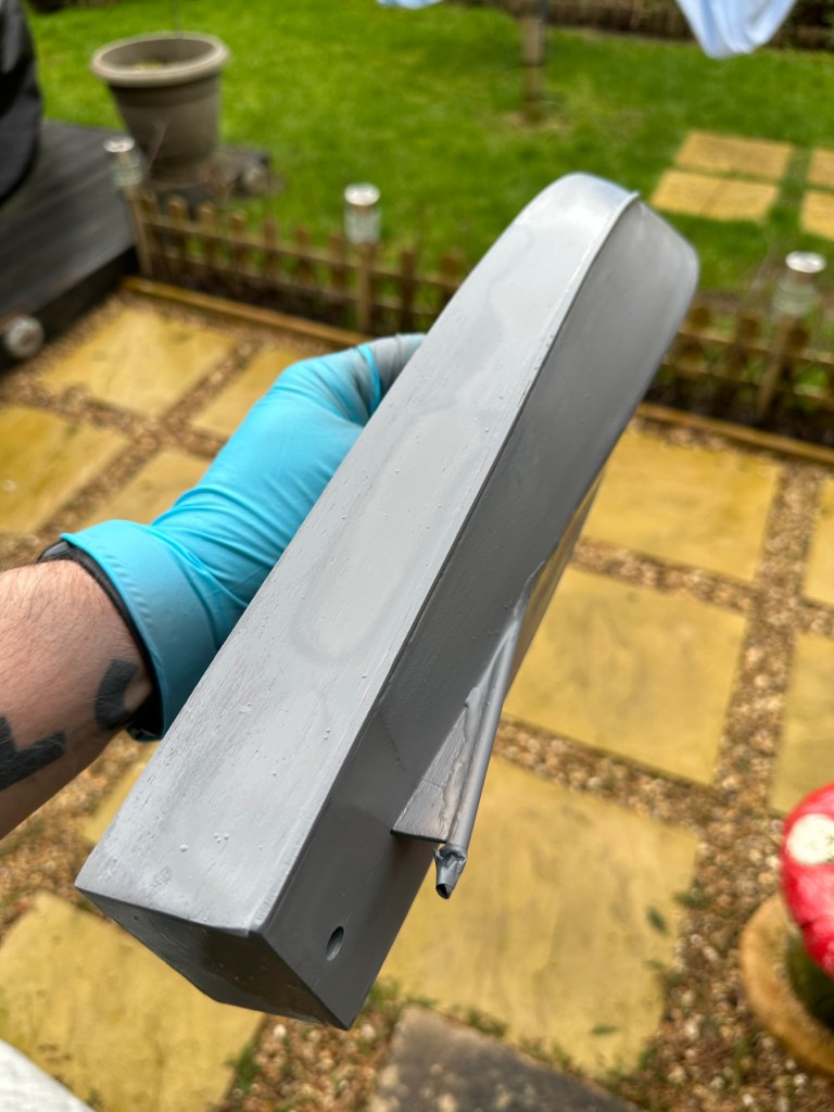
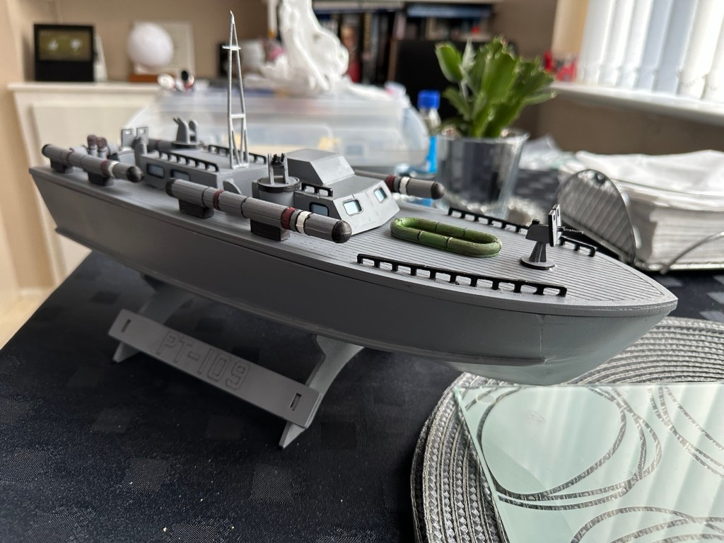
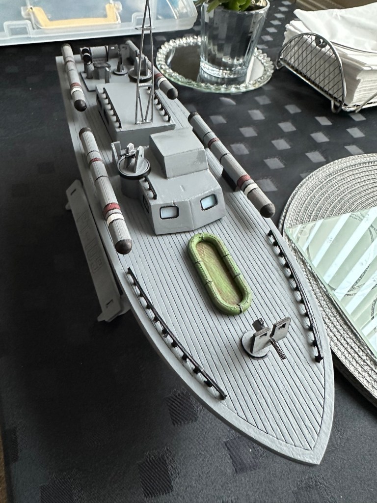
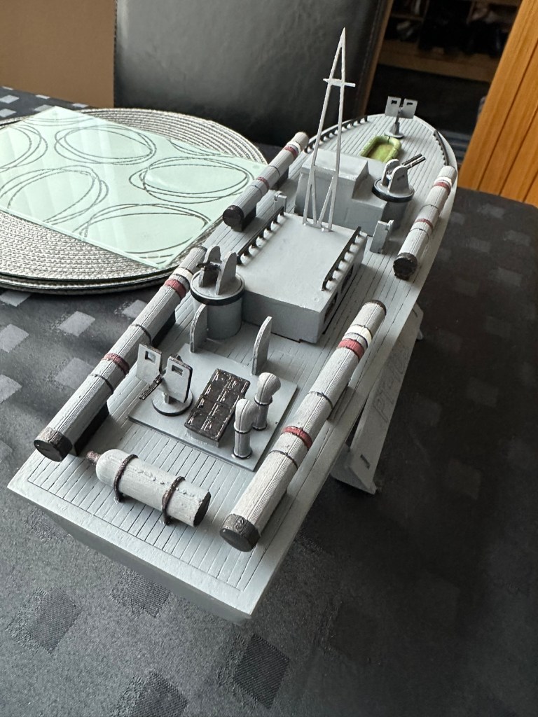
All deck weapons primed and painted

I’ve given a light sanding to a couple of spots on the hull, I’ve filled a couple of tiny holes, sanded again then re sprayed the hull. I’m happy with how it looks at present. I’m not following a traditional paint scheme, so there will be no comparison to its original appearance. I’ve hand painted some of the deck fittings, put in the cabin windows and started to fix these items into place.

I’m just awaiting some red paint to finish the hull, then I can get some decals in place. Then I can seal it all to finish the exterior of the model and then I can concentrate on setting the motor and the internal electrical elements up. Next I have to mask the area of the hull that I will paint red, I’ll do this now before the paint arrives as it just has to be right first time. I don’t want to be touching up too much if I can help it.

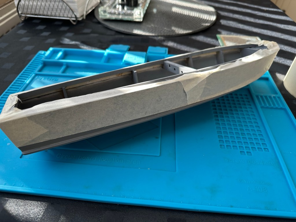
I’ve made a pair of support struts out of balsa that sit behind the aerial, I’ve changed this area completely as it was too delicate and would have been a nightmare to transport. I’ve built a modern style array for a radar, I know it’s not going with tradition but again it makes for easier transport and reduces the need for repairs on the go.

First coat with mask in place

I’ve done the first three coats of red paint for the waterline, I’m going to leave this 24hrs now before I peel back the masking to reveal what mess I have underneath. Fingers crossed on this 🤞

Masking tape all removed

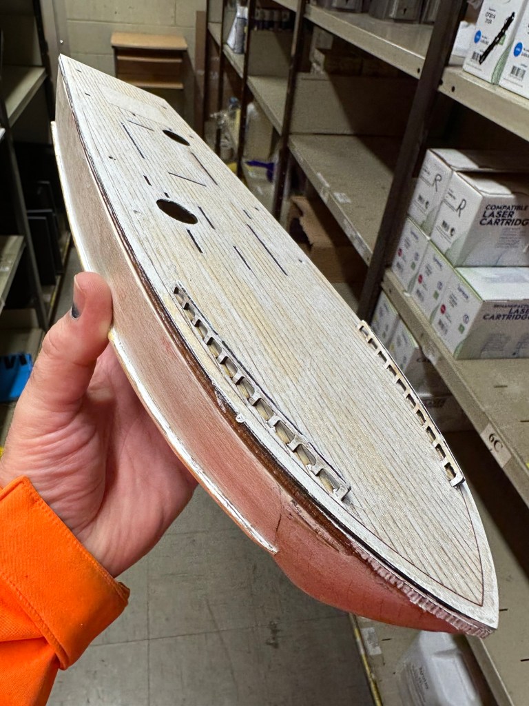
Fingers now uncrossed I’m really pleased with the outcome. The masking tape has been all removed and we now have a nice crisp line around where the red joins the grey. There’s some like marking up by the front end that believe it or not are finger nail marks when I was applying the mask. I’m not worried about this though as I have some sharks teeth decals coming that should cover this area. One of the little additions I wanted to make, to put my own mark on the build. Once all the decals are placed I will then give a final coat of a yacht varnish to seal all this work. I’m going to test a small area first as the last thing I want is for all this hard work to run into a gooey mess.

I have done the tests and commenced with coat one of the varnish. It looks gorgeous. Im probably going to do a further two light coats and that will be the hull complete. I haven’t put the decals on yet, I will probably do that prior to putting on the finishing coat.
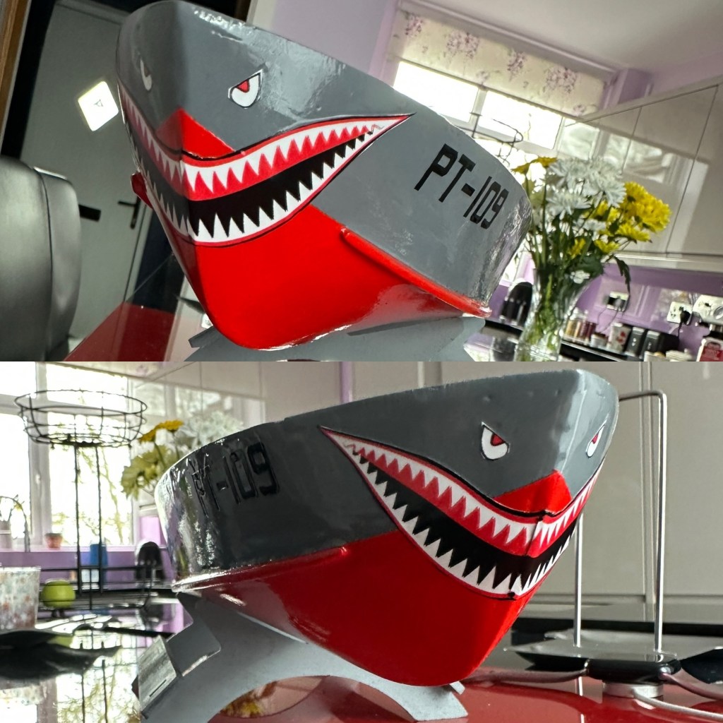
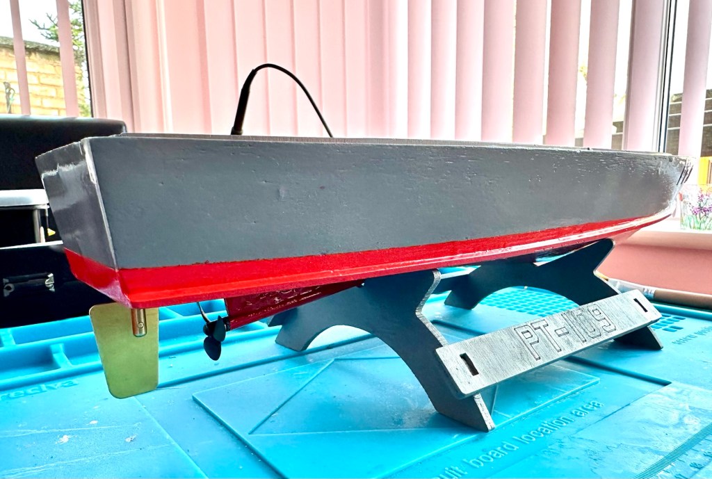
All decals applied and final varnish completed. I can now look at getting the rudder and electronics installed. I’m happy with how the whole hull area looks.
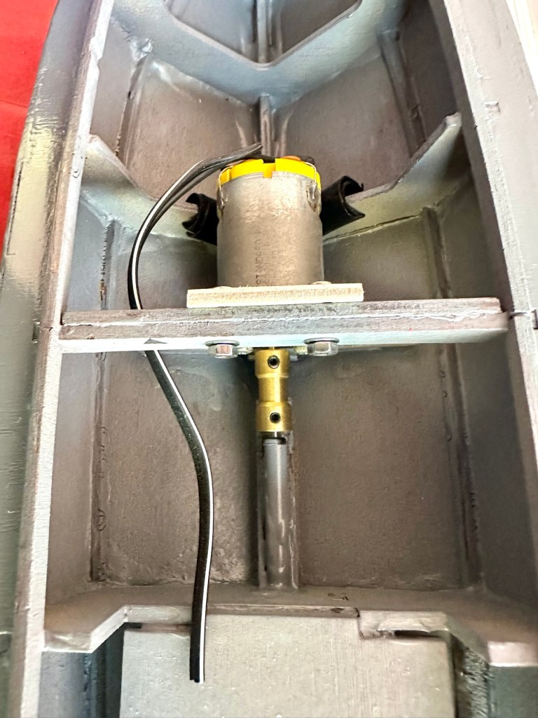
All that is needed now is to place the battery, receiver and ESC in place. I have quite a strict time on this build and I must have it ready for “Lake” trials when we go to Norfolk in June.

I will also be borrowing my brother in laws pond for 30 mins or so to do a balance and water tightness test.

Let’s get the electrics installed.

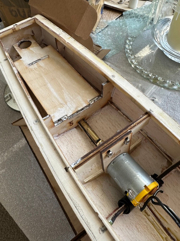
Having never really done this before, I’m quite amazed by the amount of gear I have to fit into such a small area.

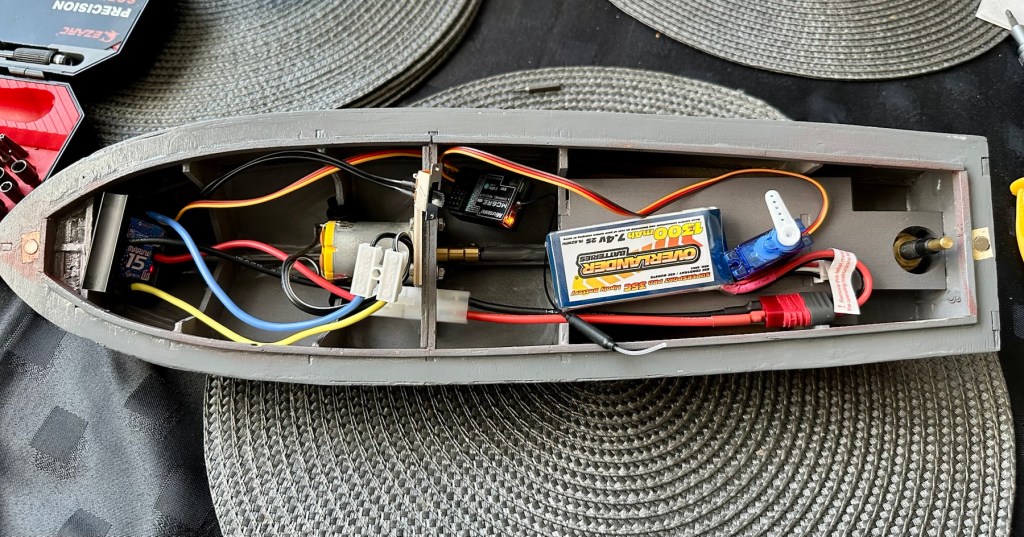
All this has to go in there….i need a bigger boat
It’s in – just needs sorting

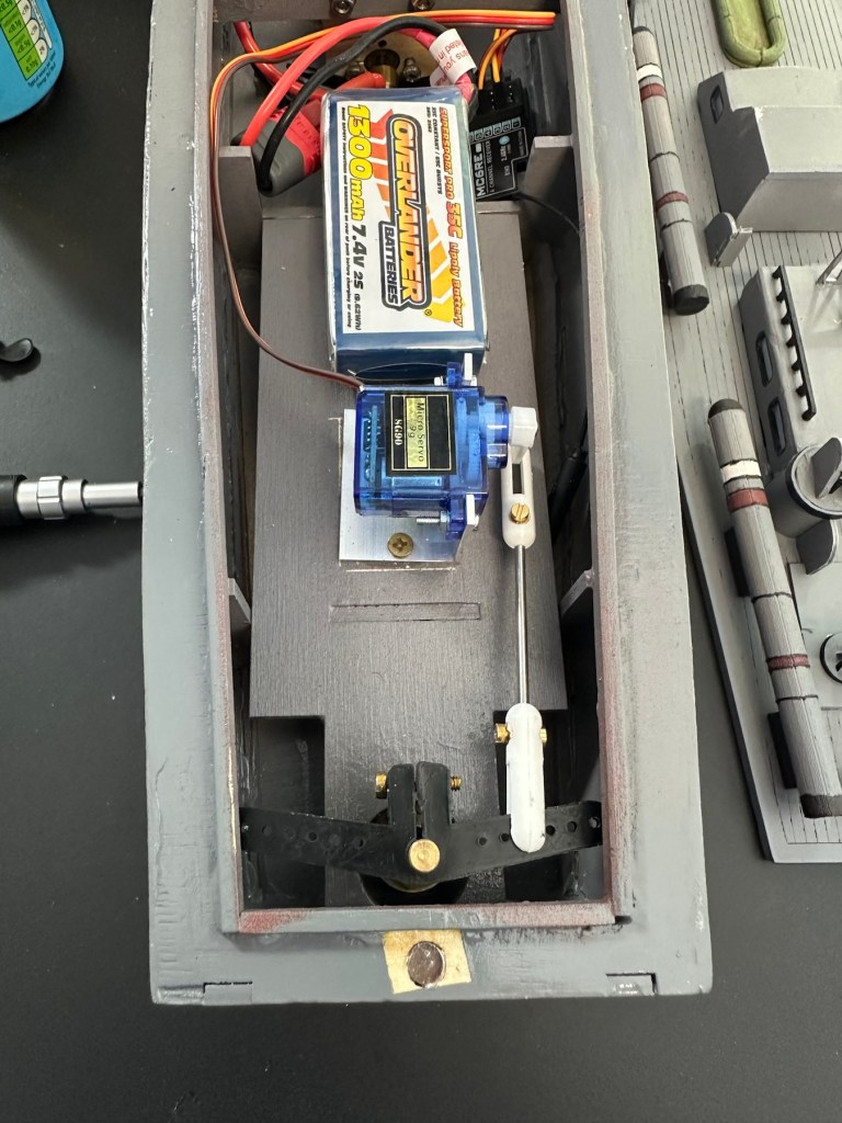
I’ve managed to put these items in-situ, in a rough position inside the hull. I need to shorten some cables, I need to somehow position the rudder servo, but I’m sure that will not be an issue. I’ve already tested the centre of balance and I’m happy with that. Later today I shall start to really tidy the layout by working from the front to the rear of the hull.
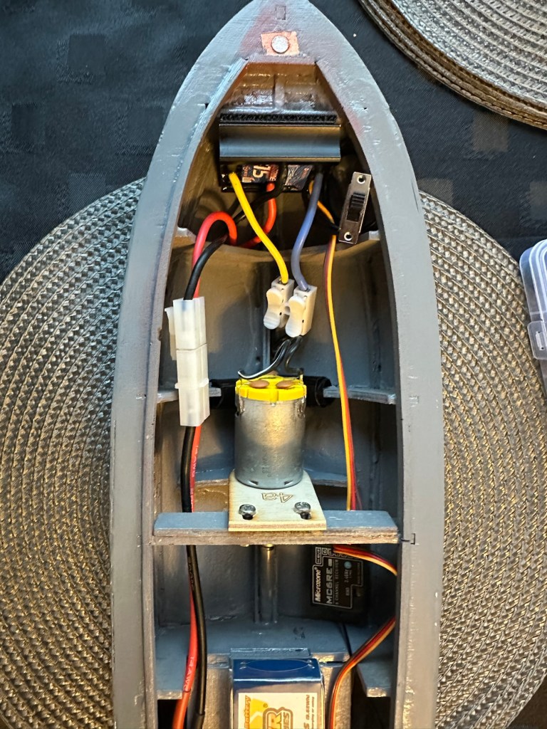
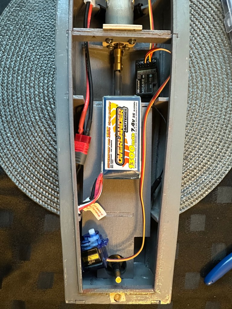
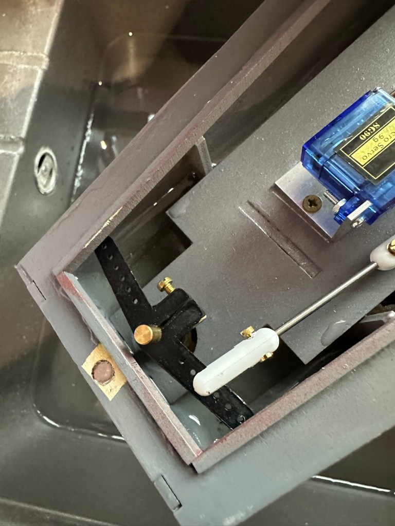
I’ve had to purchase a small bracket for the rudder servo along with a couple of connecting rods. Hopefully we can now complete the electrical connections within the hull and get the rudder operational, then I can get it water tested to check for leaks and balance.

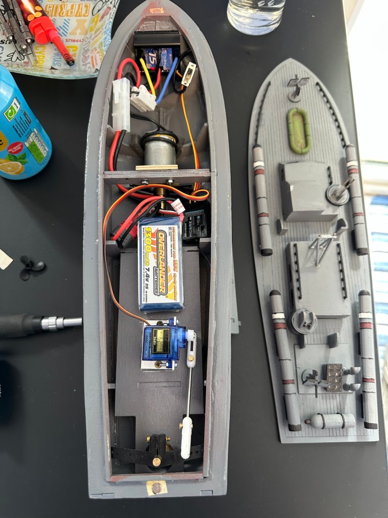
Rudder linkage in place, just needs shortening

I’ve just had quite an annoying and inconvenient moment. The rudder linkage is all now in place and working fine, however the issue lies with the propeller shaft. I’ve rather foolishly connected it all up but left the propellor flush with the shaft end so when I put on full power to test, there was a burning smell as the propeller wizzed past my ear across the room and the shaft seized up. There was such a build up of friction between the propellor and shaft that the propeller melted and bent the 2mm prop shaft out of place. A stupid mistake, caused by my rushing to get this completed.
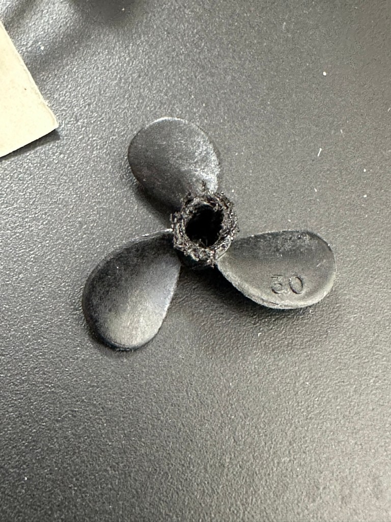
A melted propeller with the screw mechanism missing
A small video that shows the rudder mechanism working

I’ve now had to order a new prop shaft and propeller, hopefully these will arrive in the next few days and I can then get the build finished.

New prop shaft in place, and all electrics and functions are now operational with the motor purring away nicely. I’ve adjusted the distance from the prop to the shaft to reduce Friction and this appears to be working fine.
All functions working nicely

Now to sit her in some water for leak test.

The leak test was going so well, all functions worked well and she was sitting nicely in the water.

Water test

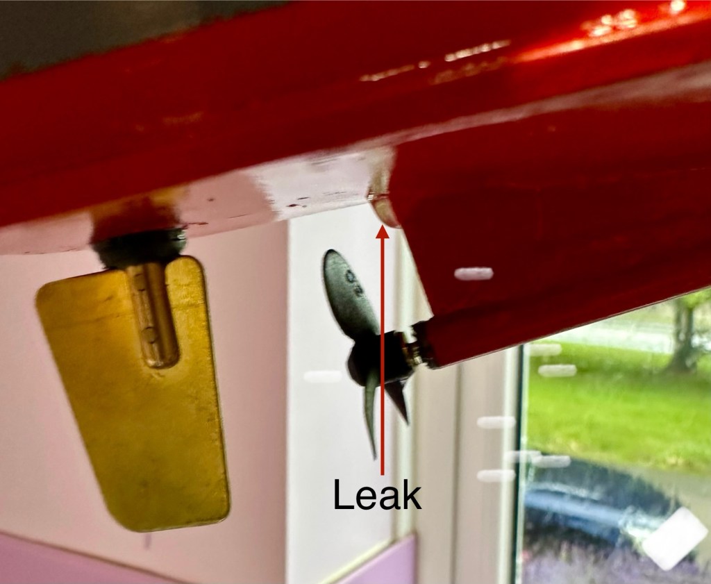
The positive here, is that there is no leak in the front end there was no water present here. All the water was in the rear, however it was not entering via the rudder mechanism or the drive shaft.

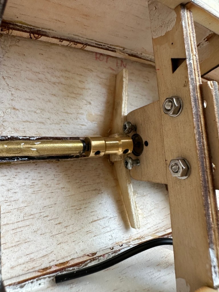
I removed the hull from the water, tilted it in such a way for the water to gather at the rear, and dried the underside of the hull. After a few seconds you could see a drip starting to gather at the top of the mount that holds the drive shaft in place. I knew it must have been a slow leak as this took almost 30 minutes to build up, I’ve caught it just before it impeded on any of the electronics.

I’ve now emptied the hull of remaining water, it’s now drying off naturally and I have a plan in place to repair the issue once the hull has fully dried. I’m probably going to use some epoxy resin to seal around the whole drive shaft fin, and then I’ll paint and seal this part again. We will then repeat the trial.

Back in the water the following morning at 07:50 after being sealed with epoxy resin on the hull, let’s leave her alone bobbing around for 30 minutes to see what occurs. It’s not good news….again.

Timelapse over 15 minutes

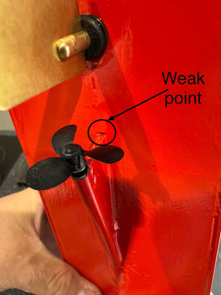
As I’m impatient, I set up my camera in time lapse mode to see if I could pinpoint where the water was accessing. My suspicions were that the water was coming up the drive shaft however I’m quite pleased that the timelapse shows this is not the case. the water appears to be accessing again from the very base of the hull. This area was sanded to quite a thin tolerance so i suspect, that even with all the sealing, two coats of paint and a coat of varnish there must be tiny holes along the hull. The previous sealing I did cured the issue at the rear, it now appears that I will have to carry on with the resin coating or something similar, along the length of the hull. To make things entirely water tight I’m going to remove what I can internally and also seal inside the hull as well.

One good soaking of polyurethane varnish later…

Three days after all this varnish has dried, I have done another float test and this one was with all equipment on board for an hour…and it was successful. We seem to be dry. I’m now putting the whole boat back together now ready for its maiden voyage at Gorleston boating lake in a weeks time.
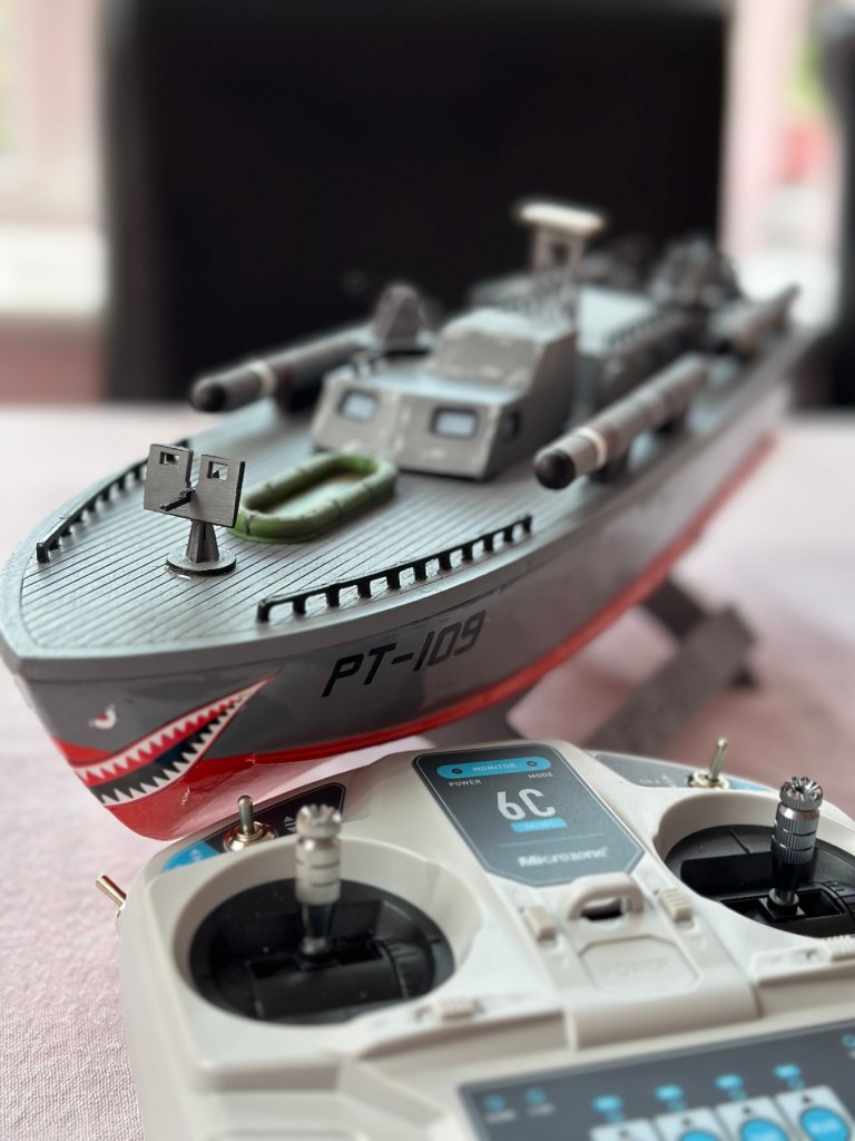
Ready to go…

I will do a separate post regarding the maiden voyage and its outcome whether positive or negative shortly after.

Thanks for passing by, as always it’s very much appreciated.

Morse code on a Psion organiser

I did my Morse test back in 2003 just after I passed my City and Guilds 765 RAE exam in Amateur radio. It wasn’t a compulsory requirement as it was in the States at that time, but I chose to go with it. I wasn’t the fastest in the world but I enjoyed using it to be able to partake in my favourite part of the hobby, low power QRP operations.

As morse uses such a small bandwidth, distant operations using very low power below 5 watts are very achievable. Wspr transmissions operate in even smaller power ranges, however that’s a whole different story.

So what’s the Psion organiser got to do with Morse?

When you set out trying to master Morse you look at loads of techniques and ways to make your journey that much easier. There are Morse trainers, there are even Morse decoders and encoders that basically allow you to “Cheat”, but what’s the point of that as you’re not going to learn anything that way.

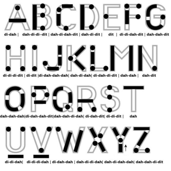
I used a technique called the visual mode technique that allows you to learn Morse by associating the dots and dashes with the actual shape of the letter and number. It works well when translating to paper, however Morse is a sound mode and it is better to use sound association, that will always work the best. I have this on a book mark to this day, as well as having it as screensaver at work. It worked for me. That’s where the Psion also had a part to play in my education.

Visual mode technique

I have a pre loaded data pack that runs perfectly on this old 1980’s machine. I used a very similar program back in the day, but not this actual one (See pictures above). The program and files are extracted and copied from the Interair Airnav pack and i have uploaded a small video below to show it whilst working.

“Peace”

With this program every digit you press on the keyboard is repeated back to you in Morse code. It’s a fantastic way to keep yourself on the ball. There are a few minor errors but the numbers and letters are pretty much spot on. It’s a great way to learn the shape of a word by sounds, and that’s a big part of Morse code, where you use phonics or the sound and shape of a string of dots and dashes to learn particular words or formations of groups of words. I’m probably making it sound more difficult than it actually is, and I apologise for that as it really doesn’t have to be. Each person finds their favourite way to learn, and this worked just fine for me all the way back in the early 2000’s about 22 years ago.

Have a great day and peace to you all or should that be :

.- -././.-/-.-./. (Check above) 👆

Duga radar

What’s that then? I hear you ask. Well since I became a radio amateur (M0ESB) back in Feb 2003 anything regarding radio has fascinated me.

The Duga or – Russian woodpecker issue of the early 80s has always been an item of interest to me. It was allegedly constructed as a Russian over the horizon early warning system and was replaced in the late 80s when satellite systems took over the early warning mantle.

However it obtained notoriety by creating havoc on the airwaves worldwide for quite a considerable period of time.

This video by a fellow Amateur radio enthusiast M3HHY explains quite eloquently, in 11 minutes what the issue was. Some great photos of this absolutely massive antenna array can be seen in this video.

And whilst we are still here this is what Wikipedia has to say:

The duga system was extremely powerful, reaching over 10 MW, and emitted in the shortwave radiobands. It was given the nickname Russian Woodpecker by shortwave listeners for its emissions randomly appearing and sounding like sharp, repetitive tapping noises at a frequency of 10 Hz. The random frequency hops often disrupted legitimate broadcasts, amateur radio operations, oceanic, commercial, aviation communications, and utility transmissions, resulting in thousands of complaints from many countries worldwide. 

Courtesy: Wikipedia

I hope you find this as fascinating and informative as I have. Radio remains to this day special to me. I’d sooner be listening to it in any form rather than watching a tv. In my eyes or should I say ears, it was the most significant invention ever made, if only Marconi knew back in the 1890s just how important this communication method would become he would have been blown away. It has helped to shape so much, our modern day world, and how we communicate with each other on a daily basis.

Do You Know Vail Code?

Alfred Vail (public domain) We talk about Morse code, named after its inventor, Samuel Morse. However, maybe we should call it Vail code after Alfred…

Do You Know Vail Code?

PT109 wooden torpedo boat kit – construction

This years birthday, I’d hinted that I wanted to build an RC model boat from scratch, and that’s what I got. A good friend of my wife and I came up trumps and brought me this nice little wooden boat starter kit. I’m fairly experienced at building balsa gliders and planes from plans and have done quite a few. I’ve never ventured into boats though so this is a first for me. It all stems from going on holiday to Norfolk, where we normally stay in a place called Gorleston where there is a nice boating pond that two of my brother in laws sail prebuilt trawlers that they have brought, i’ve always said that I’d join them on one of our trips, jokingly saying I’d get a submarine or battleship to blow them out of the water. However i wouldn’t do that, and this is the first stage of venturing into the world of model boats. I’ve now just got to build it.

Boating pond at Gorleston

The boat that i have chosen is made by the wooden model boat company distributed in the Uk by JPerkins models. It is a PT109 torpedo boat modelled on the one that John F Kennedy sailed in, in the Pacific theatre after a collision with the Japanese Destroyer Amagiri in which Kennedy’s actions to help save his surviving crew earned him a Navy and Marine Corps Medal. I’m going to put my own touch on the paint scheme though and not go with the traditional all green or grey. I’m going to mix it up a little by highlighting and brightening up the look of the boat a bit.

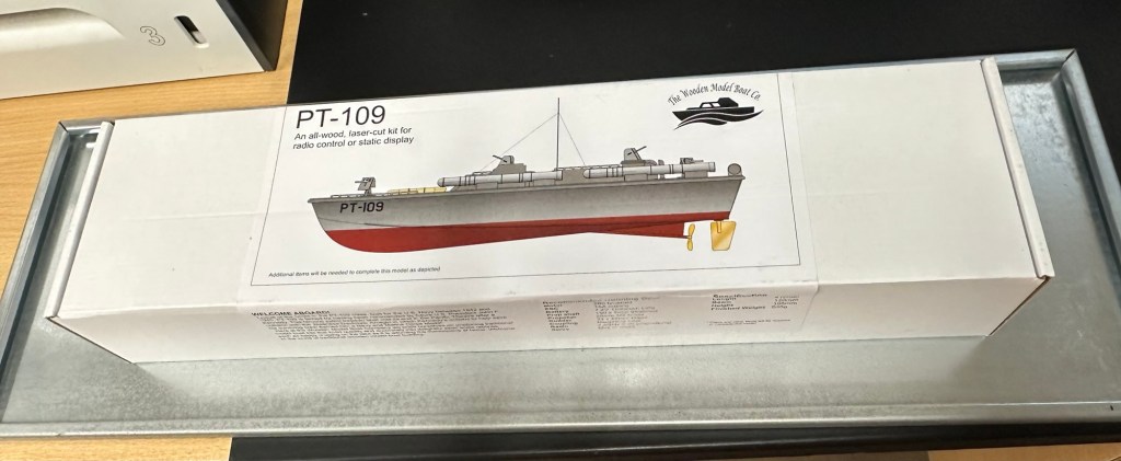
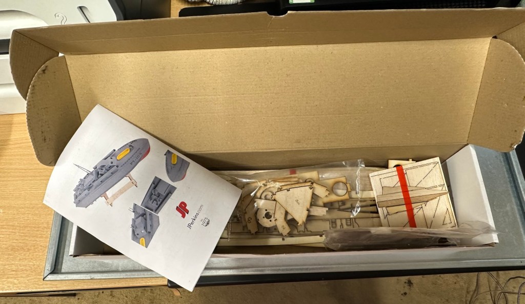
The boxed kit

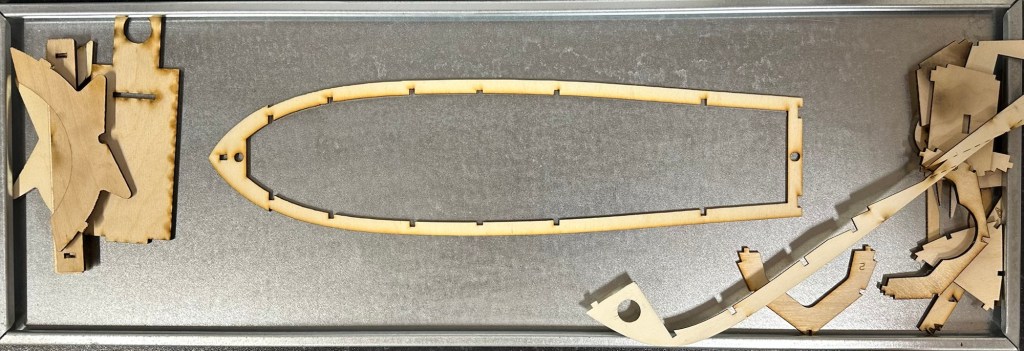
These kits have laser etched parts, its my first experience with them and my only gripe so far is that some of the parts are so small and delicate that this process cremates the object because of its small size. I have had to make some of my own parts for this kit as in some cases it’s just like trying to press out burnt wood from the etched parts. Not good in my honest opinion, and as this is a starter set it’s more than likely liable to put a beginner off of the hobby to be honest. Not everyone is able to easily replicate the missing/damaged parts.

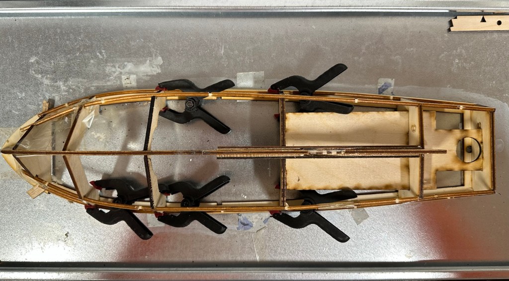
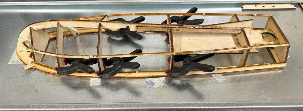
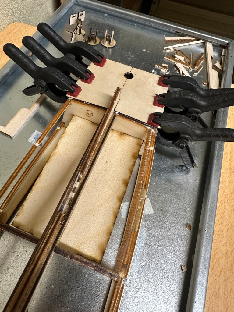
Firstly you have to secure the deck frame to a flat surface using some double sided tape. This is so you can start building the hull frame and prevent warping. I use a small steel shelf for my base that can easily be moved around and stored between sessions.

There is a lot of time between sessions where you just have to leave parts to dry, you can quite easily try to do so much and potentially ruin all the good work you have done. Patience really does have to be a big part of what you do in build these models, the old adage of measure twice, cut once needs to be used so mistakes are kept to a minimum. You can make tiny adjustments when in the finishing process but for the time being you need to adhere to instructions as much as possible. Check and double check and always dry fit prior to gluing in place.

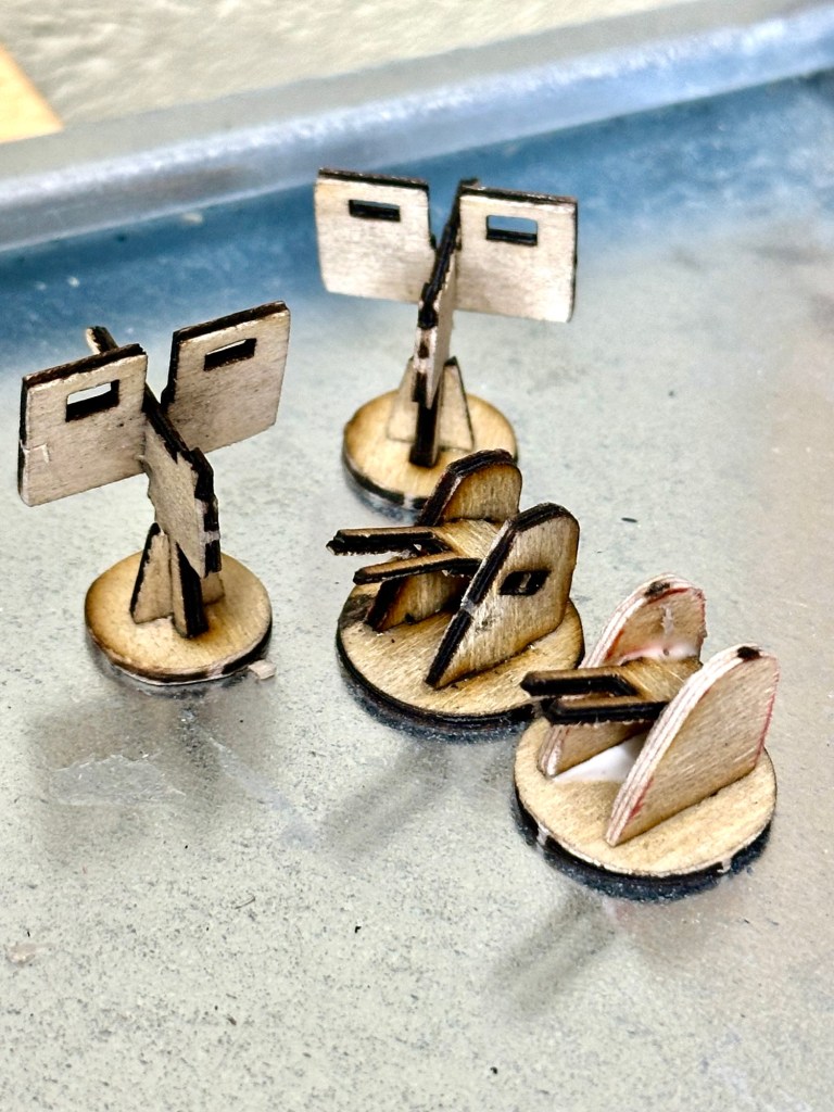
If you look at the picture below you will see how the laser etching burns really small parts. This doesn’t look good however they will look a lot better after they are sealed and painted, if I left all the parts like this the whole project would look as if it had been in a fire. I’ve had to build some of these parts from scratch as the kit itself had insufficient parts pre cut.

Burnt small parts…to be finished

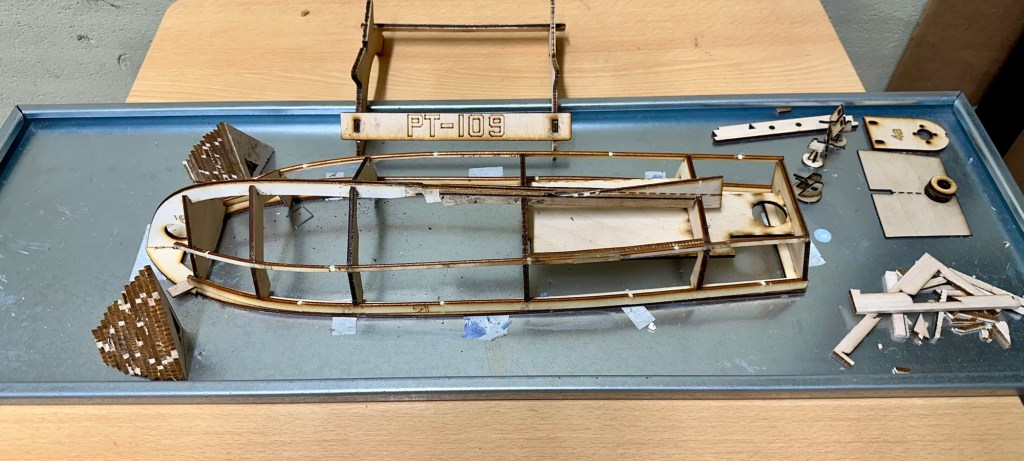
The hull framework is now complete, next stage is to get the outer skins on, the bow formers in place and then hand sand, fill and sand again until the whole hull is ready to be sealed. Again there are issues here with the kit as one of the hull skins is two times thicker than it should be, hence the amount of bending required to shape the hull is not achievable. I have brought this up with the supplier and within a few days I have had a new set of replacement hull skins sent free of charge. Their customer service has been superb and it is good to see that some companies do still try their utmost to keep their customers happy. I will now progress with completing the hull.

These four boards form the outer skins. At 1.5mm they are very flexible. However you can see the second one from the left is twice as thick and not pliable enough. These were replaced by the supplier within a few days of notifying them of the issue.

Below is a small video of the completed framework. It has probably taken about 8 hours in total to get to this stage (plus many more hours to allow glues to cure)

The hull framework complete

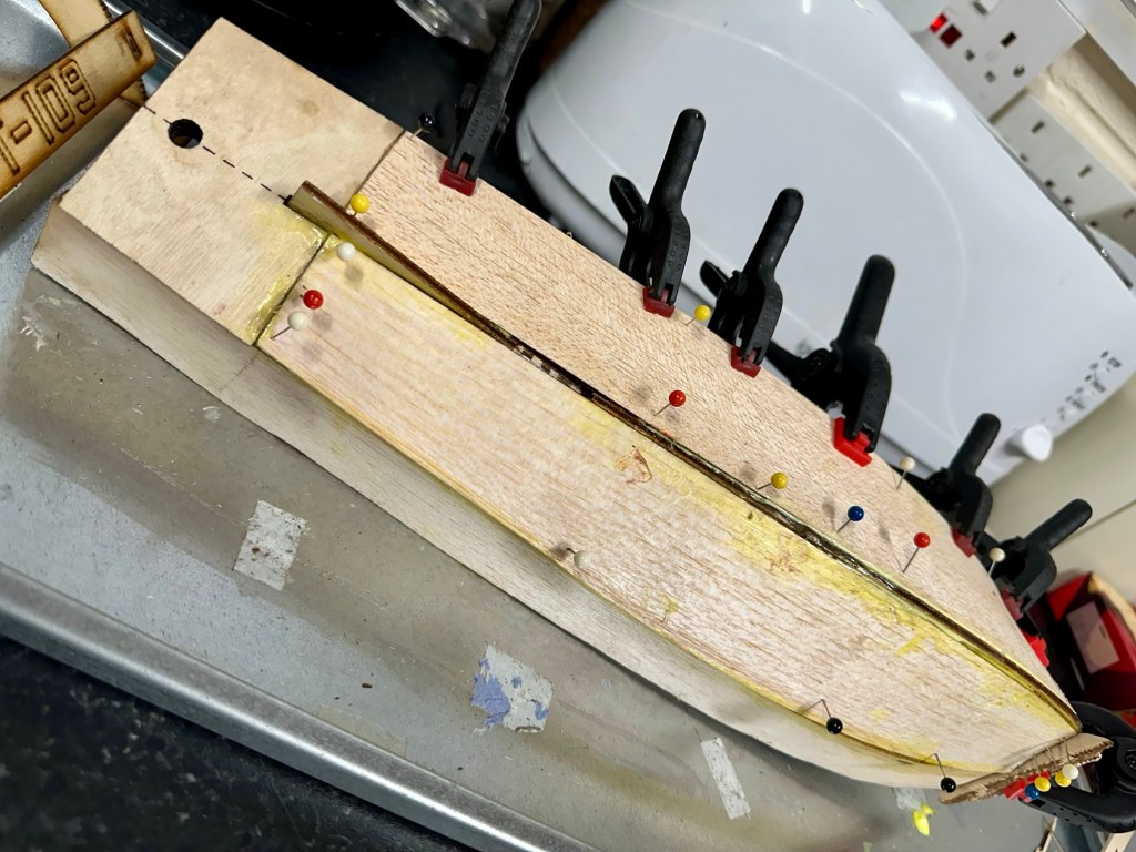
So tonight over a period of about 8 hrs I’ve managed to get the 4 balsa skins that form the hull into place. I’ve had to do a bit of re shaping and minor alterations, and the final bend of the skin would have bust it under the strain if I didn’t decide to wet it first. Wetting balsa allows the inside edge of the sheet to bend in, making these big bends in the hull shape possible. That as well as plenty of pins and clamps with epoxy resin ensures the skin stays where it is put. I left about an hour between each skin placement before moving on to the next one.

Here is the hull, assembled ready for sanding filling and all the other fun stuff required to make it look good and waterproof.

The hull ready for sanding, waterproofing and painting.

Tonight I have given the first heavy sanding with a course paper. This has really brought the hull up lovely. The former’s that were put in place have now been sanded to form a good bow profile. See photos below.

I now have to do a small bit of filling with balsa filler and then I will sand with a finer paper.

Looking more like a boat

Once the final sanding has been done I can then look at sealing the exposed wood and then begin the waterproofing and painting. The installation of the radio gear will go in place towards the end of the build. In the meantime I just have to build the superstructure on to the top deck. This will require some small bits to be painted before being put into place.

I’ve built the superstructure and that has been set aside to cure. There will be a lot of sanding and painting needed. I have attached the deck now and all those items will attach to it, and i must say it’s looking quite good.

I’ve now detached the deck and gone around with some balsa filler and hopefully tomorrow once it’s dry I can give it a sand with some fine paper and then I can look at putting on a coat or three of sanding sealer.

I’ve tonight managed to get coats one and two of the sanding sealer applied with sanding after each coat with a fine sandpaper. The torpedo tubes have been assembled along with other items and we are now very close to getting the painting started. However first I will give a final sand to the structure to see if it is ready for the primer. If not it will mean applying some balsa filler and applying coat 3. There really is no rush. I need to now get the prop tube in place and permanently positioned prior to any painting. I am considering a number of different paint combinations at this stage, but they are changing on a daily basis. I wonder what colours I will go with?

I’ve done the all the sanding and I’m now happy to commence the undercoat of the hull. I’ve fitted and removed the rudder and engine to test they fit ok, the boat is now bare and ready to paint. I’m going to individually paint the guns and superstructure before fixing to the deck. I might paint the deck with a dark varnish, I haven’t quite decided yet.

Part 2 of this post will cover the painting of the boat. Coming sometime in Feb 2025.

Subchannel Stations: The Radio Broadcasts You Didn’t Know Were There

A good article on subchannel transmissions. Courtesy of Hackaday.

Analog radio broadcasts are pretty simple, right? Tune into a given frequency on the AM or FM bands, and what you hear is what you get. Or at least, …

Subchannel Stations: The Radio Broadcasts You Didn’t Know Were There

The World Morse Code Championship

Interesting to read this. I passed my RAE exam back in December 2003. We didn’t have to master Morse code but I did take it on and even today I’m ok at deciphering it, if a tad slowly. I could transmit it at about 8 words a minute, and if I’d stuck at it I’m sure I’d have become better.

But like most things i just didn’t have the time available to further it. I do still like to put the radio on occasionally and listen to slow Morse on the amateur bands.

If you were in Tunisia in October, you might have caught some of the Morse Code championships this year. If you didn’t make it, you could catch the …

The World Morse Code Championship

Slow scan television on an iPhone

There is a form of amateur radio comms that I enjoy and that is slow scan television. Here’s a basic explanation:

A literal term for SSTV is narrowband television. Analog broadcast television requires at least 6 MHz wide channels, because it transmits 25 or 30 picture frames per second (see ITU analog broadcast standards), but SSTV usually only takes up to a maximum of 3 kHz of bandwidth. It is a much slower method of still picture transmission, usually taking from about eight seconds to a couple of minutes, depending on the mode used, to transmit one image frame.

Since SSTV systems operate on voice frequencies, amateurs use it on shortwave (also known as HF by amateur radio operators), VHF and UHF radio.

Wikipedia

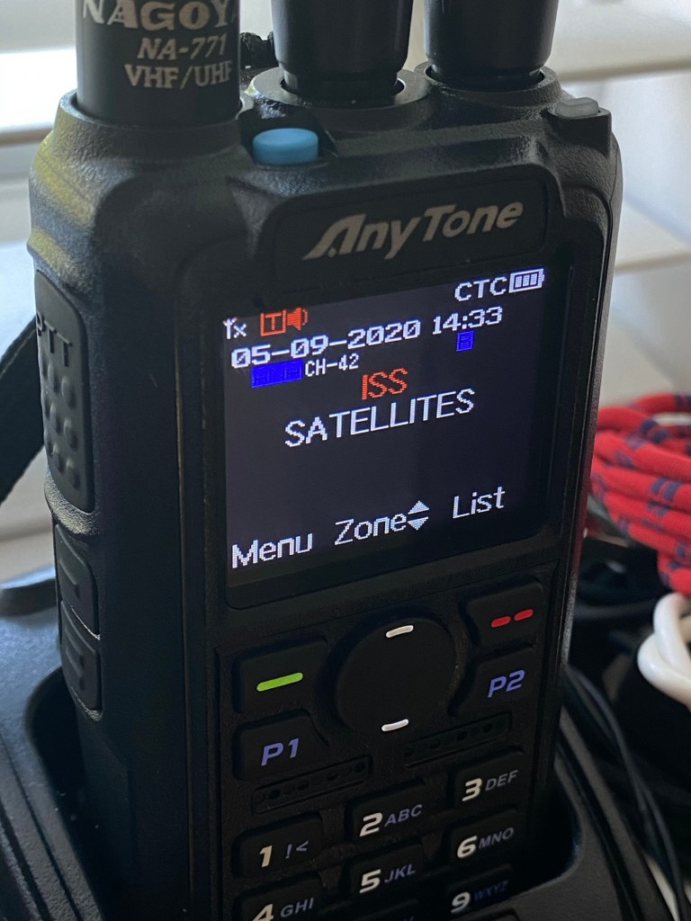
In this Instance below I used a digital transceiver and was pointing the aerial in the general direction of the International space station as it passed overhead on a specific date, when the Russian section of the ISS was transmitting slow scan television pictures as it passed over. I used my iPhone to decode the signal and to produce the pictures, using an app I had installed earlier. This was all part of a day celebrating the anniversary of Sputnik, the world’s first man made transmitting satellite.

My setup was totally mobile and so basic that I just about managed to get partial scans via this technique, see the two pictures below. I was literally sitting in the front seat of my car.

Even though my pictures were not perfect I was still able to supply proof that I received the transmission and as a result was issued with the certificate below from ARISS – Amateur radio on the International Space Station, find out more about ARISS Here: ARISS

ARISS certificate

There are many of these types of events that occur all year round where you can experiment with all types of equipment to make contact with distant radio stations. This is the spirit of amateur radio.

Technics Mash SL-XP165 Portable Cd Player With XBS Bass

The listing states:

For parts or not working, Does not power on don’t know what is wrong with it,screen looks to have a leak

EBay

Technics SL-XP165 portable CD player

This is probably going to be one of if not the least problematic units I have received yet. Probably more along the lines of boring for those looking for a repair report, I fear I have brought you here under false pretences, that was not my intention and I apologise if that has been the case.

Another unit from 1996 (therefore now 28 years old) this one originally had rechargeable batteries which were a bonus item for such a unit at the time. Personally I’m using good old alkaline batteries for test purposes, I doubt I will be using rechargeables.

I down loaded the instruction pamphlet, grabbed a pair of earphones and then dropped in two AA batteries and a CD.

Nothing. Silence…..

I looked at the unit, the seller is right I thought….then I pushed the play button and took the switch off hold on the side and put the second switch into normal operation and almost blew my ears off.

Superb sound and it was quite obvious that the unit was working. All buttons are doing what they should do, the Xbass system is phenomenal and the volume dial is faultless and crackle free.

It just goes to show the seller in this case wasn’t fully aware regarding how the unit works. You have to turn it on and off to get it working, it’s not all automated like other similar units. See video below.

Stop start works good

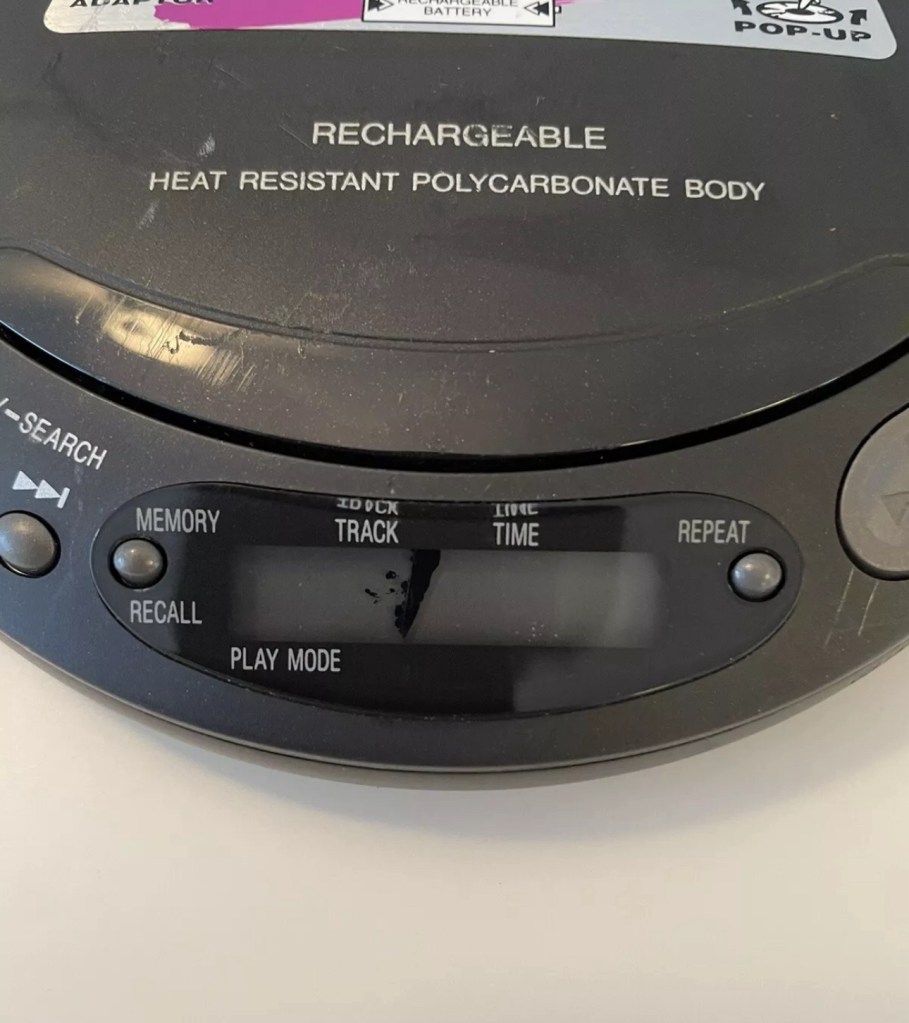
The unit is a bit tatty and the indicator panel has had some leak by the looks of it (See photo at top of this post) but even though this looks a bit poor cosmetically it does still display most of the information, it’s just not showing the track number info. Yes I could probably try another screen on this unit but what is the point? It works fine and the unit will gain no significant value for doing such a fix. It’s just not a financially viable choice unless I somehow come across a no value donor unit and seeing the prices people think these units are worth, I can’t see that happening anytime soon. And the Sony donors I have just aren’t compatible.

So I’ll leave it as it is. As the saying goes, “if it ain’t broke, don’t try to fix it.” It isn’t faulty, the only fault was in the sellers knowledge of its workings.

Another one saved from landfill. And that’s a positive.

AIWA Personal Radio Cassette Player HS-TX406 assessment and repair

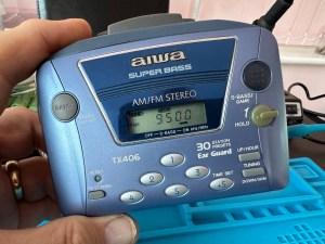
I recently purchased this item, you can read the original post here: AIWA Personal Radio Cassette Player HS-TX406 

I love this little unit, it has a great radio reception probably better than a number of Sony Walkmans I have worked on to be honest. It has arrived in good cosmetic condition with only a few dinks and scratches commensurate with its 30 year plus age.

Radio works well

On opening up the unit it’s patently obvious that this is another drive belt issue, it’s saggy and breaks on removal. Luckily I have a replacement belt that I purchased earlier.

It’s another saggy worn belt issue

And that is basically it. No major dramas it’s as simple as replacing the belt.

Speed adjuster circled

A bit of light grease on the gears, a tweak of the speed adjustment and all sounds as it should.

I’ve used a calibration tape with a 3Khz sine wave, it’s tuned in pretty close to the tone and I’ve used a downloaded oscillator software package to check the matching. It’s not a professional setup but it’s fine for my requirements.
All working with a new belt

Sorry there is nothing else much to write but I have a good working unit that plays tapes well and all I can say is I’ve saved yet another easily repairable unit from landfill. I already have someone who wants to take this one off my hands so I hope it will have many more years of trouble free operation.

Jobs a good ‘un 👍