Simple as that. And yes it’s a tiny radio but in excellent condition cosmetically.
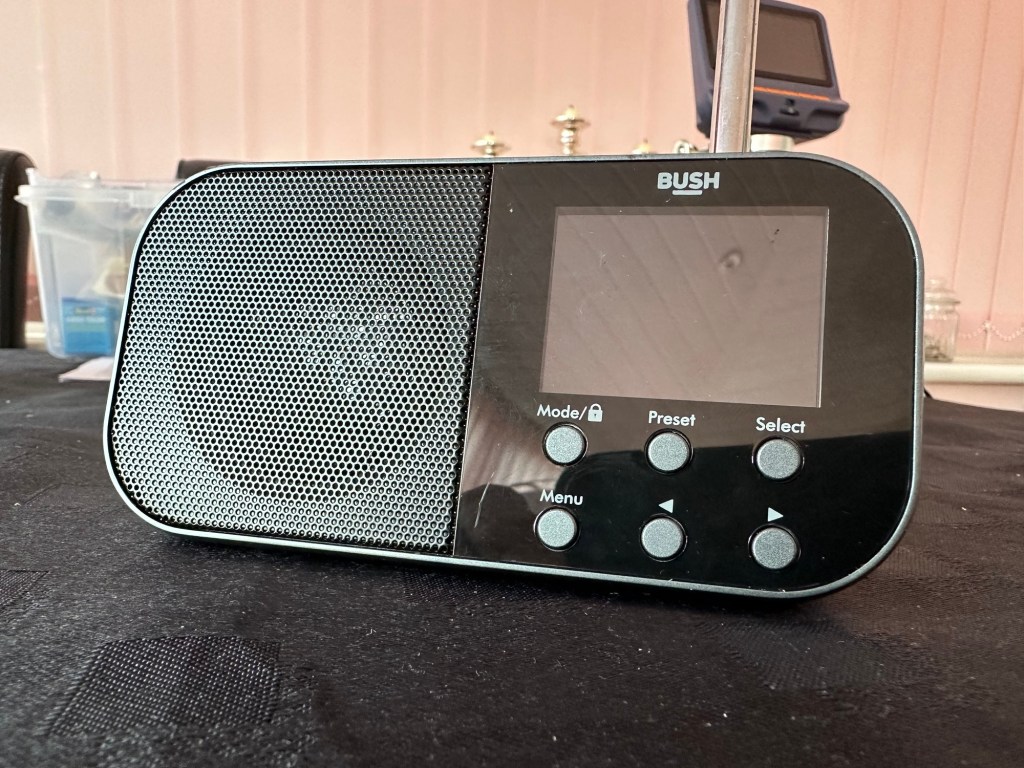
Bush handheld
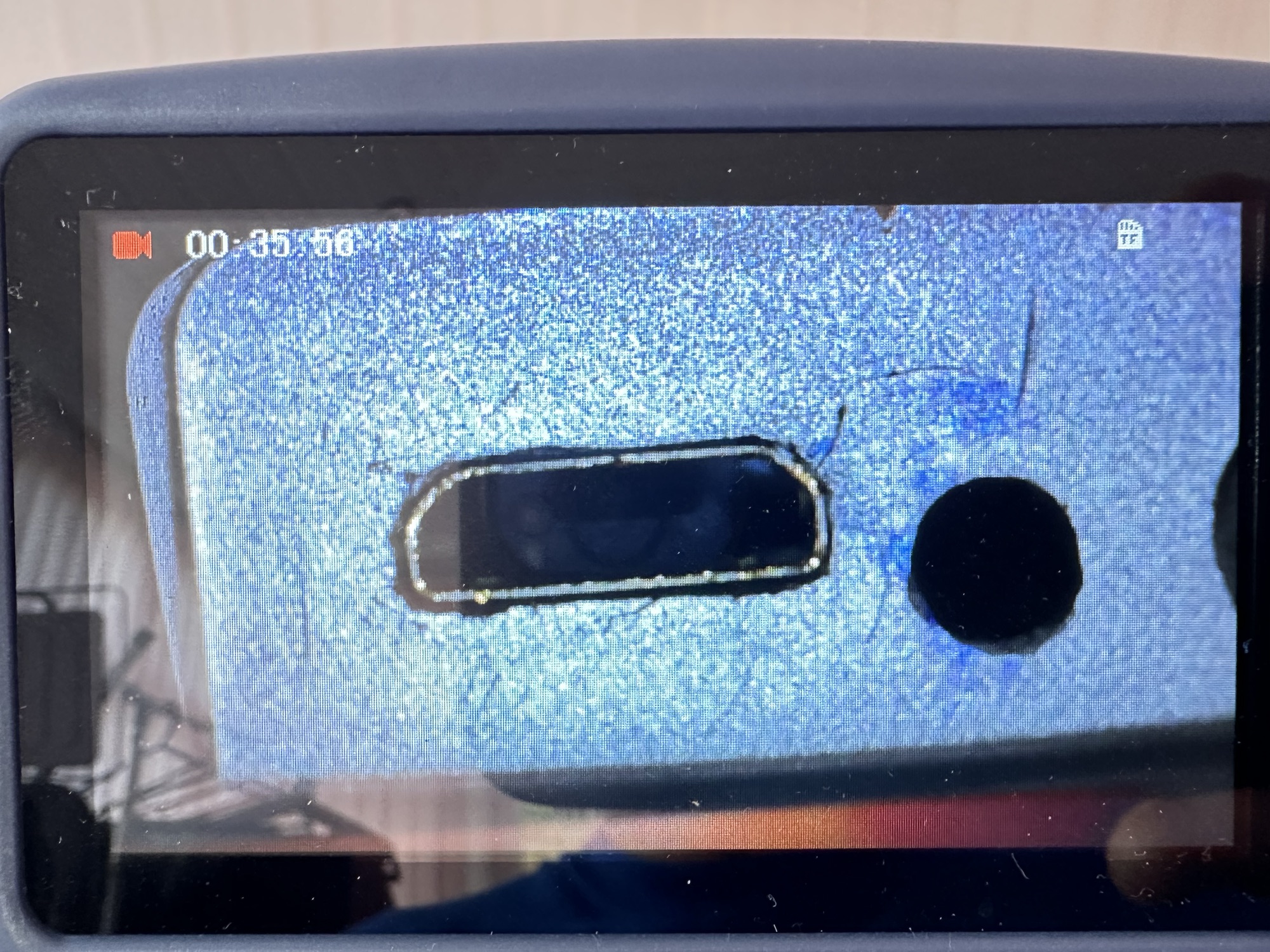
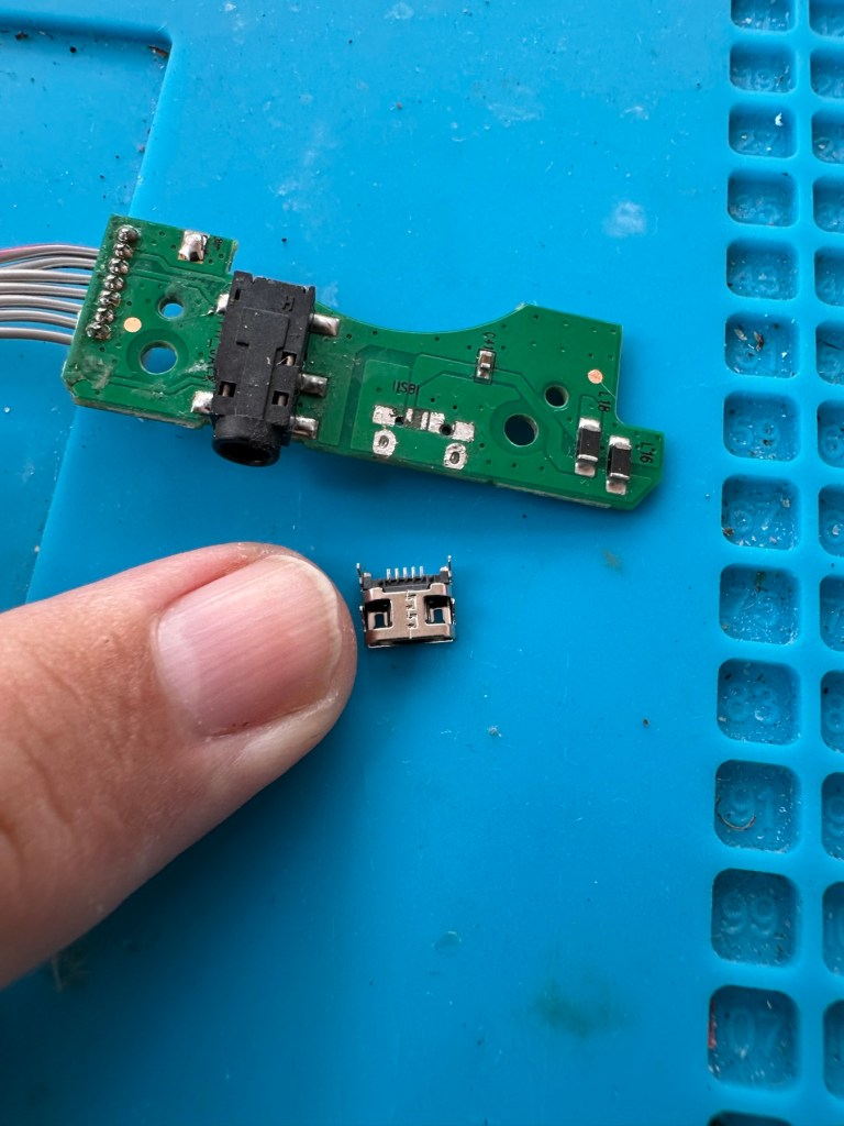
On inspection it’s obvious that the micro USB port is damaged and will need replacing.
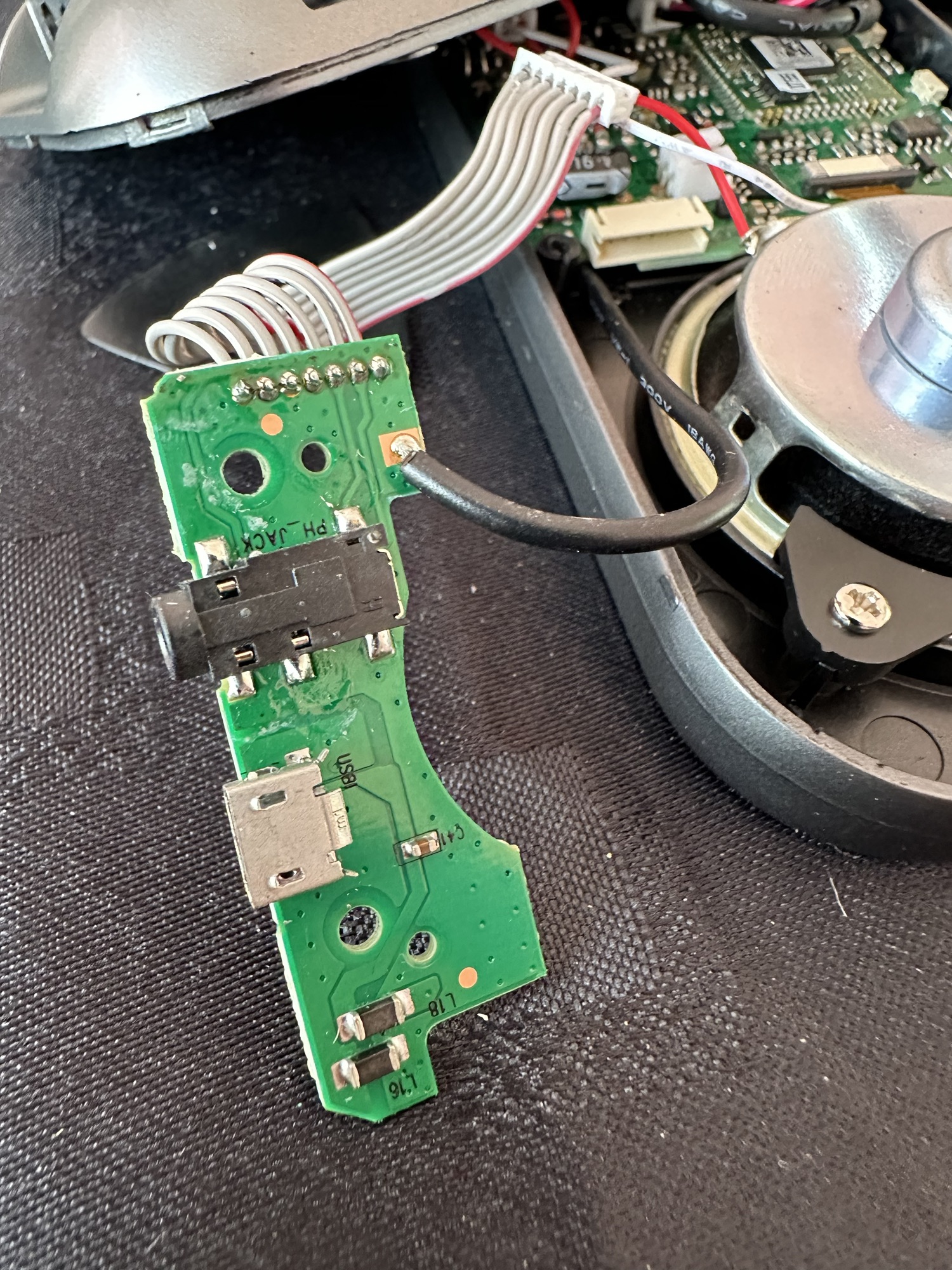
Broken micro USBWhat’s wrong?Power board
I’ve ordered some replacements USB ports from our friends in China so I’ll have to wait a few weeks before I can progress this project any further.
Micro usb ports
The ports have arrived from China, so let’s look to see if we can repair this unit.
*This project has been on the back burner since May 2024. 13 months later and I’m now on it*
Hello all, time to clear that backlog and what better place to start than here. I do in fact have two of these with the same problem so this is a two for the price of one project.
This should be a simple case of replacing the faulty charging ports that are both micro usb ports. They are small believe me.
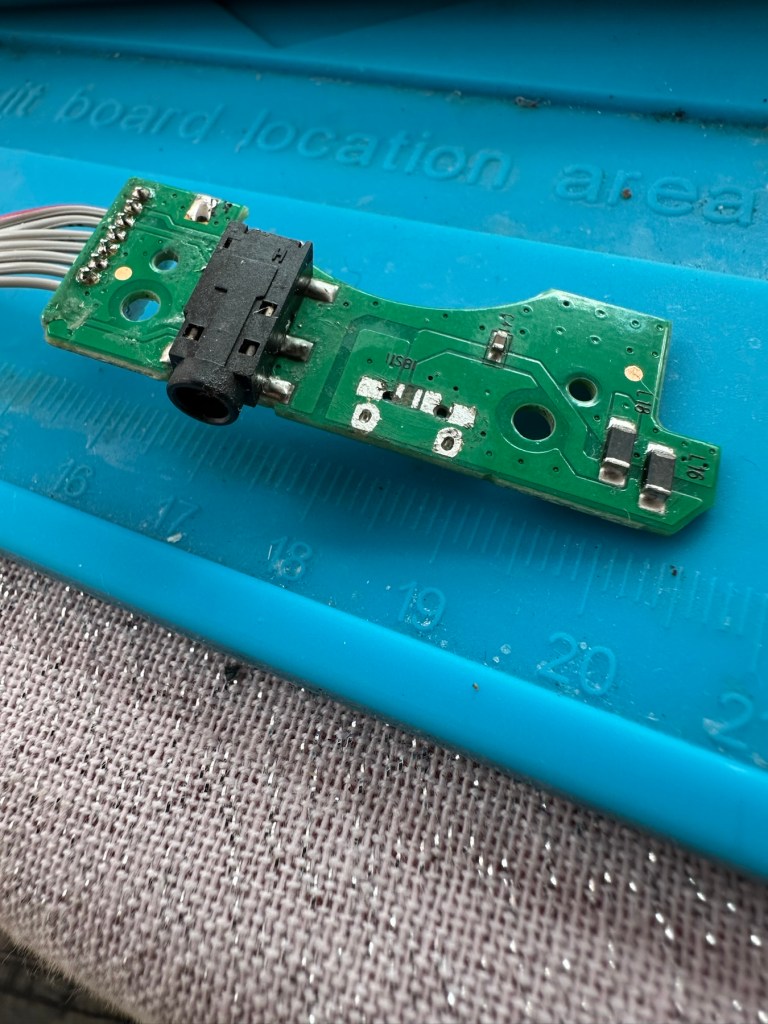
Old port removedNew port that has to be fitted
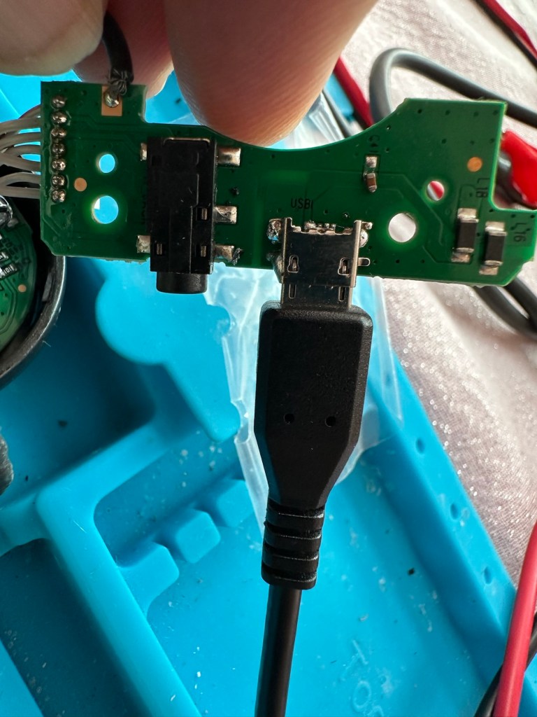
There has to be some preparation before we can get the new port on. Using a soldering iron and flux and a little solder wick, I clean the old board remove the old solder and give a good clean with IPA. I then prime the small connections on the rear of the charge port with a little solder. Now I put the port to the board and tack on the earth points. Then using a rework hot air gun I blast the port at about 350 degrees Celsius and hold the port in place with some tweezers until I see the solder glisten and melt around the port. I take the heat off and let the solder set before moving the tweezers and when it’s cooled a bit I check that it’s setting straight, all connections are good and solid. I then just add a tiny bit more solder to the anchor points for strength.
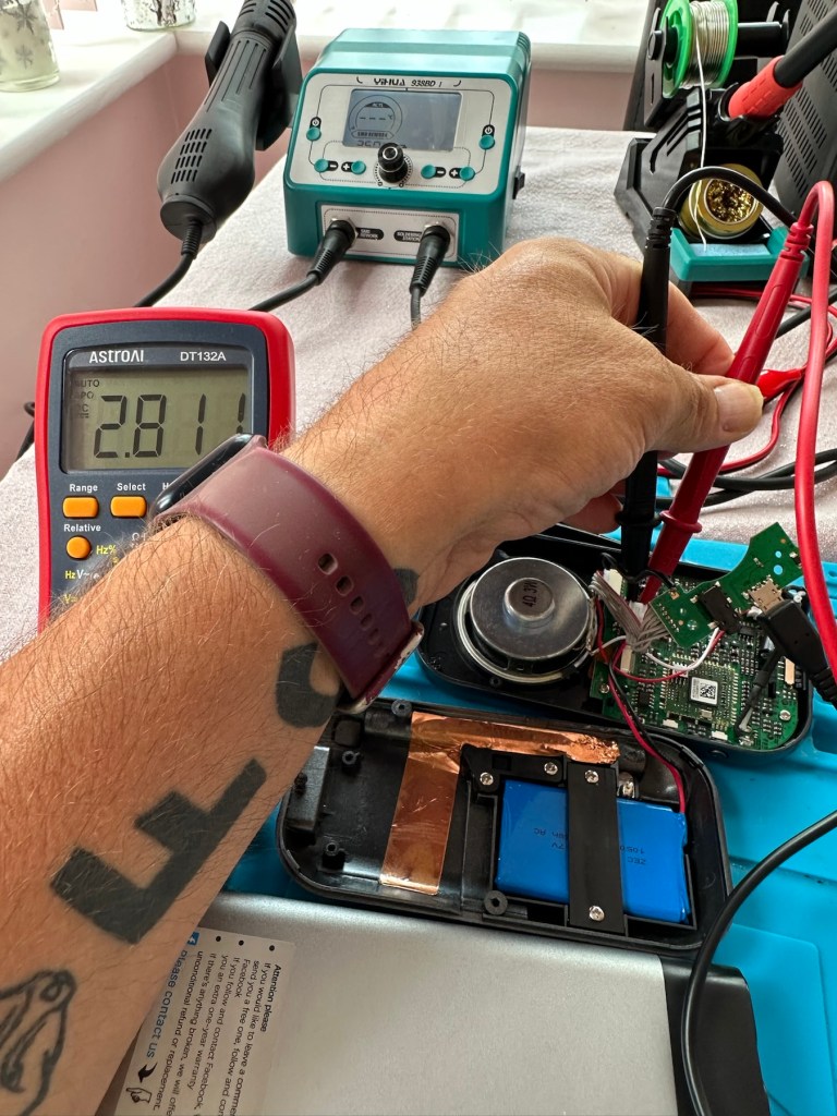
Whilst this is cooling down I check the status of the battery. It is a 3.7v rated battery and is currently holding a charge of 2.8v. It’s a little low but far from being dead. The second battery shows a similar charge.
Battery level
After the solder work has cooled I use my battery pack connected to a small ammeter to see if the radio and more importantly the battery is demanding any power.
Power cable connectedWe have a power demand from the battery.
Well that’s good news, 5v in and the demand from the battery is 0.96 of an amp. The battery is charging. And the fix is as simple as that.
Two perfectly good radios
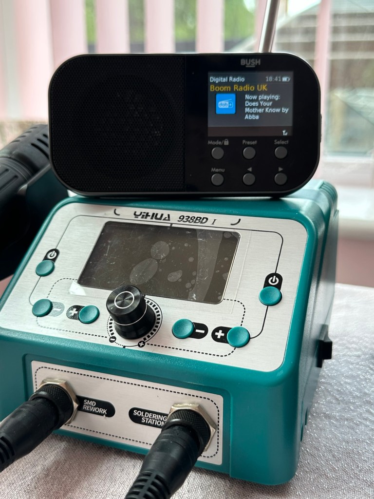
A little bit of soldering aerial contacts and a couple of other wires back into place and the whole unit clicks back together. Two screws inserted in the rear and time to switch on. Both radios tune in perfectly and the sound is surprisingly good for these little units. I’m keeping one in my work space at home, as I love having some music around me, I’d sooner listen to the radio any day as I hardly watch TV. The other radio will go into my work locker for when I’m working nights or in the workshop.
In my work space, but it won’t be staying here…
Im very happy with this little project, it only took about an hour and I don’t know why I left it so long. Another couple of items saved from the tip, it amazes me that these units probably all suffered with the same problem of inferior parts that failed early on in the radios existence. Kind of scares me just how many did go to landfill.
Two cracking little radios
Well at least these two are going to carry on for a few more years yet. And that’s a positive in my eyes.
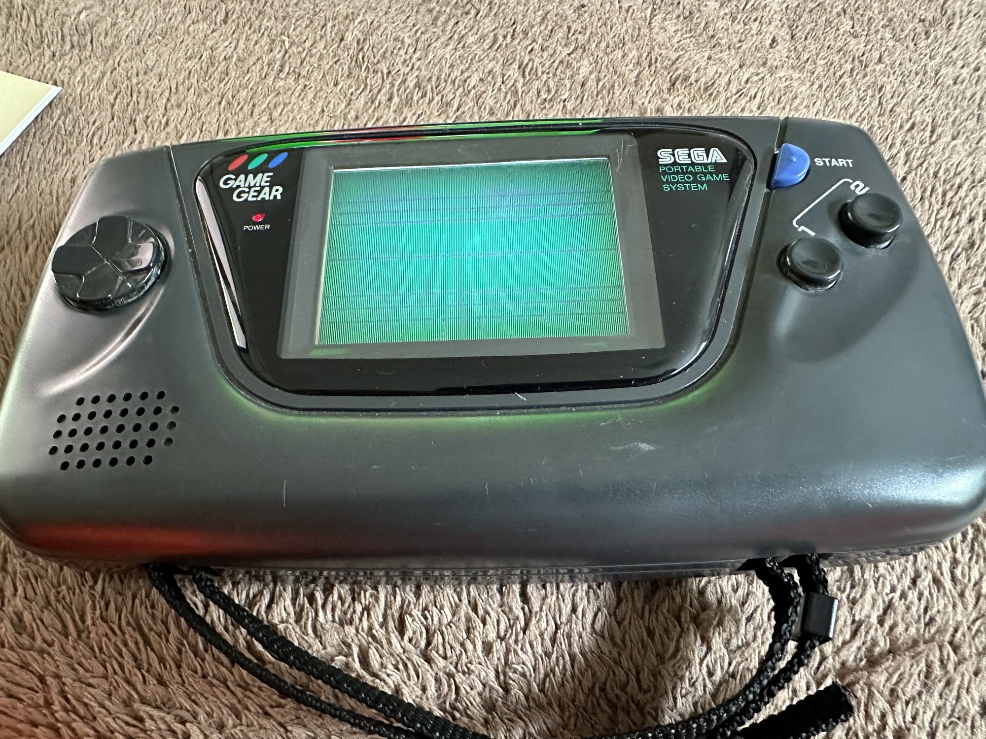
You may wish to refer to this post: Sega game gear 2110-50 where I purchased a non working Sega Game gear and brought it back to life.
The (I thought it was repaired) Game gear
I’m now ready to do some modifications on this unit, and I will save the replaced items for use on later projects.
Pretty much every Game Gear that was ever produced (and that is approximately 10.6 million units) has suffered with the dreaded (Capacitor plague) that I have discussed in an older post. The first job that is recommended to be carried out when purchasing an old Game Gear is to replace the old capacitors, it’s quite an easy task and nine times out of ten will remedy any issues that you have and allow you to continue gaming for years to come.
However there are other issues.
The screen is an old tube powered system that is exceptionally power hungry, you can replace this with much superior LCD versions, I’m withholding from doing this at the moment as I want to get as much use out of the old screen, and to be honest my unit doesn’t require replacement just yet, there’s still life in the old girl. I’m sure that this will be a future project though.
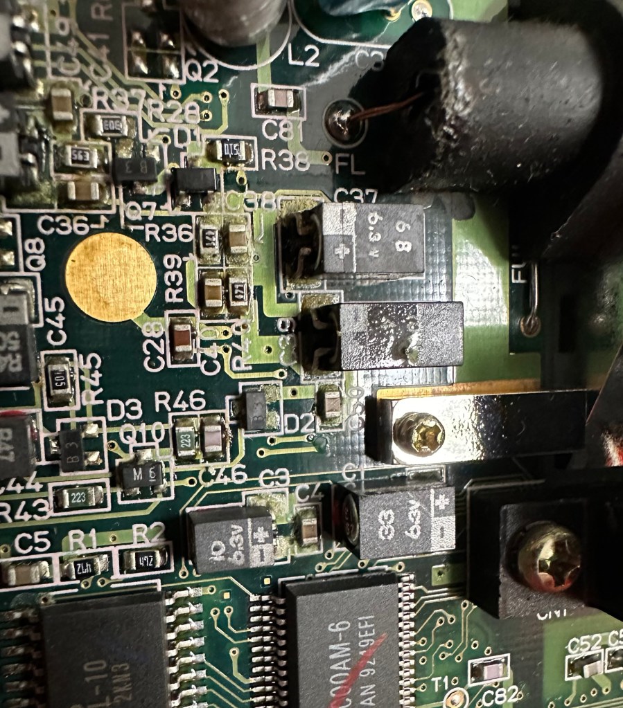
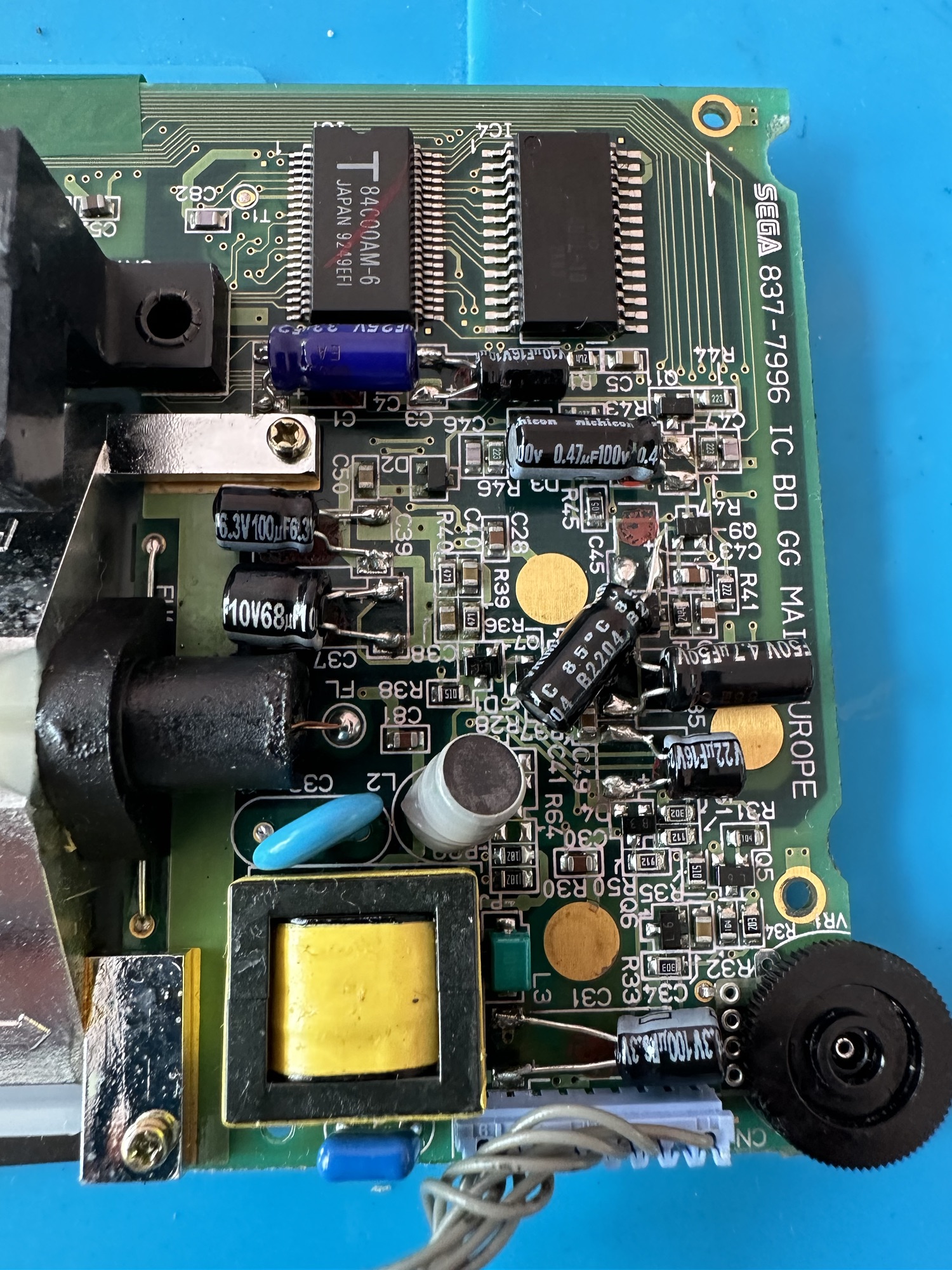
Occasionally after doing the capacitor replacement on the power board, other components such as a small IC and three transistors that control voltages across the system, start to misbehave causing the unit to switch off after just a few seconds. This is currently occurring with mine and I am intending to replace these components to see if this sorts out my issue. I have also ordered a replacement power board from China that is a fraction of the cost of a European one, it may work, it may not but if the change out of components dosen’t work at least I’ll have an alternative option.
There are a few checks we can do prior to replacement of these components on the power board that will confirm the various voltages required by the system. It’s best that these tests are done prior to diving in head first to replace them. You could be just wasting time. You may need a new power board or maybe even consider converting to a rechargeable battery system. It’s all doable.
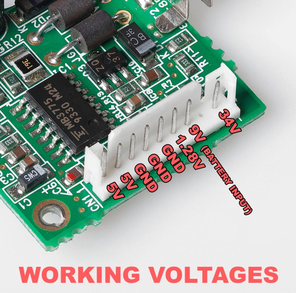
Expected voltages – photo courtesy Retrosix
Here are the results from my test of voltages on the power board, I’ve injected 9v via a bench power supply to the battery contacts on the board:
At the 34v pin I had 0v
At the 9v pin I had 8.9v
At the 1.28v pin I had 1.28v
The three ground pins read as ground
At the two 5v pins I had 0v
So as a result I obviously have an issue with the 5v rail and the 34v rail, I believe the 5v rail is the one that affects the boot sequence and the 34v is not an issue at the start up, however, it’s there for a reason and this simple test proves there is an issue. I will therefore only change the IC and three transistors as the capacitors were changed when I did a full recap.
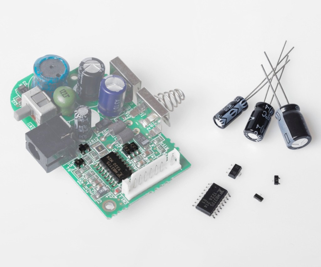
Advertised shellWhat actually arrived Clean Amp duo soundPower board components Three of the above Photos courtesy of Retrosix
For my modifications I am getting a new clean amp duo audio board with dual speakers instead of the single mono one that is standard. This is an upgrade on the original, extremely efficient and with better sound processing.
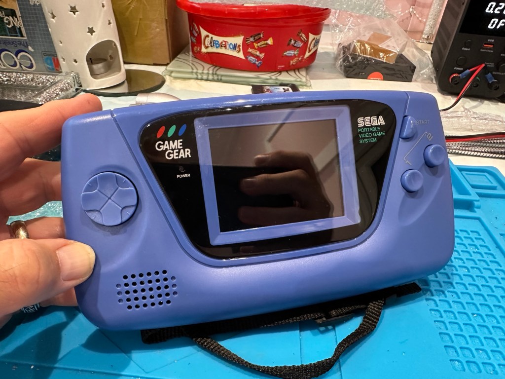
I am also replacing the shell with a new Blue case and glass to replace the scuffed old screen, this shell also has dual speaker outlets to compliment the audio board replacement. The shell is already prepped to accept a rechargeable battery system should I decide to install it at a later date.
I shall be getting these upgrades from Retrosix who specialise in supplies and modifications for gaming consoles.
All the items have now arrived and the first thing I’m going to do is sort out the replacement IC and transistors on the power board. The rest is fairly straightforward. However they have sent me the wrong shell, a single speaker one instead of a dual speaker one, so I’ve now got to await a replacement, annoying!
Scratch that, they are saying that they never did have any duo speaker ones even though they were advertising them on their site ( as per picture above..) and after a protracted discussion with the supplier / owner i’ve come to the conclusion that he might think he is a wizard at modding and designing circuitry but is totally and utterly inept at customer service, he wouldn’t know good service if it bit him in the ass. Hey ho on we go, it is what it is.
If you choose to use them in the future then just be aware. They have an uncanny knack of trying to pin their inadequacies and mistakes on you, the customer. Caveat Emptor – as they say.
So now the sound will be original mono, but hopefully improved. I have a spare speaker and mount as a result and I can use the new clean amp duo board in a mono configuration. Should I get a duo speaker shell sometime in the future I can always do a swap out.
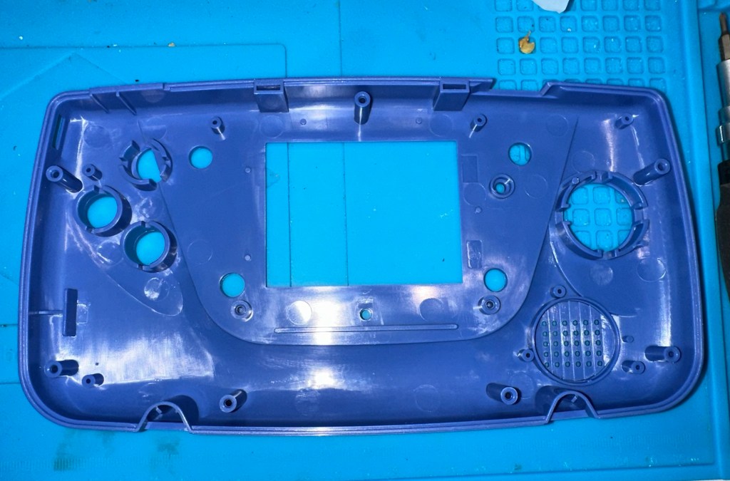
Blank shellNew speaker and buttonsBlank shell and new speaker and buttons
Today I’ve taken the empty new shell and installed the new audio card and speaker, as well as the new buttons and silicon pads. I’ve then installed the main board minus the power board that still needs the new components.
New board and old boardMain board installedAudio and power boards connected
I’ve also installed the new front lens on the unit and I must say it looks nice.
New front lens on unit
Let’s get to the difficult bit, replacing the components on the power board. I’m not joking when saying that some of these items are not much bigger than a grain of rice. I suspect a lot of bad language will be used here, as this is a new level of soldering for me. I’ve never replaced anything so small before. If I balls it up I’ll just have to await my cheap Chinese power board.
Ok, the power board from Ali Express got here really quick, to be honest even before I could set some time aside to change the components on the old board, so therefore I’ve decided to try this new board as a straight swap.
I will keep the the components and the old board to use at a later date.
First though I have used the bench power supply to test it is ok, and it’s a big tick on all voltages as per the test I did on the old board. All voltages are stable and consistent, so I have secured the board in place and put the required batteries inside. Works perfectly.
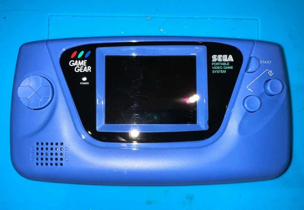
Back together, awaiting the big switch on
Working perfectly
I now have a perfectly good looking updated Game gear that I am exceptionally pleased with. The sound system is a good upgrade, it has a really loud volume (adjustable) and is crisp. The powerboard from China at a total cost of £10.80 is an absolute bargain, and works perfectly with good stable voltages. The case is good, fits well and the lens is clean easy to install and scratch free, the whole thing looks brand new.
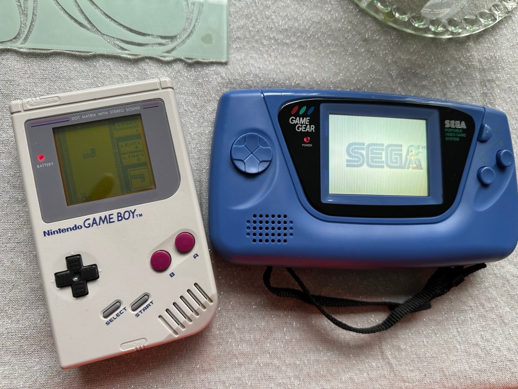
Two old rebuilds, rejuvenated
I now have two perfectly good looking and working examples of 90’s retro rivalry in perfect working condition. The plan is to display these in the house, on a custom made display. I’ve really enjoyed working on this little project and I’m made up with the outcome.
The only things left to be done would be to change the power supplies to rechargeable and to change the screens to new IPS/LCD screens, but I don’t think I’m going to do that on these two, I’m keeping them original or as close as possible to original, I want to keep these as they are, to cherish in this condition for as long as I can.
And that was it. Faulty. What’s faulty? I’ll not know until it arrives as i didn’t ask. Foolish perhaps, but I was looking for a challenge and something I could later mod. I think I’ve found it.
Sega GG frontSega GG rear
I must admit I was looking for a cheap way into a retro gaming repair and I believe this was it. Most damaged game gear units seem to be averaging around the £42GBP price but I managed to get this 2110-50 version at a lower price of £28GBP (and I may have got a game with it, let’s see what arrives!). However I don’t know what the heck is wrong with it but I suspect it’s the usual issue that has plagued these 90s retro units since their inception where the capacitors fail catastrophically.
There is probably not a single one of these units out there that has not suffered this issue or is certainly guaranteed to do so sometime in the not too distant future. Imagine how many of these units have just been discarded as junk considering that 10.62 Million units were sold up to and including its discontinuation date in April 1997….scary!
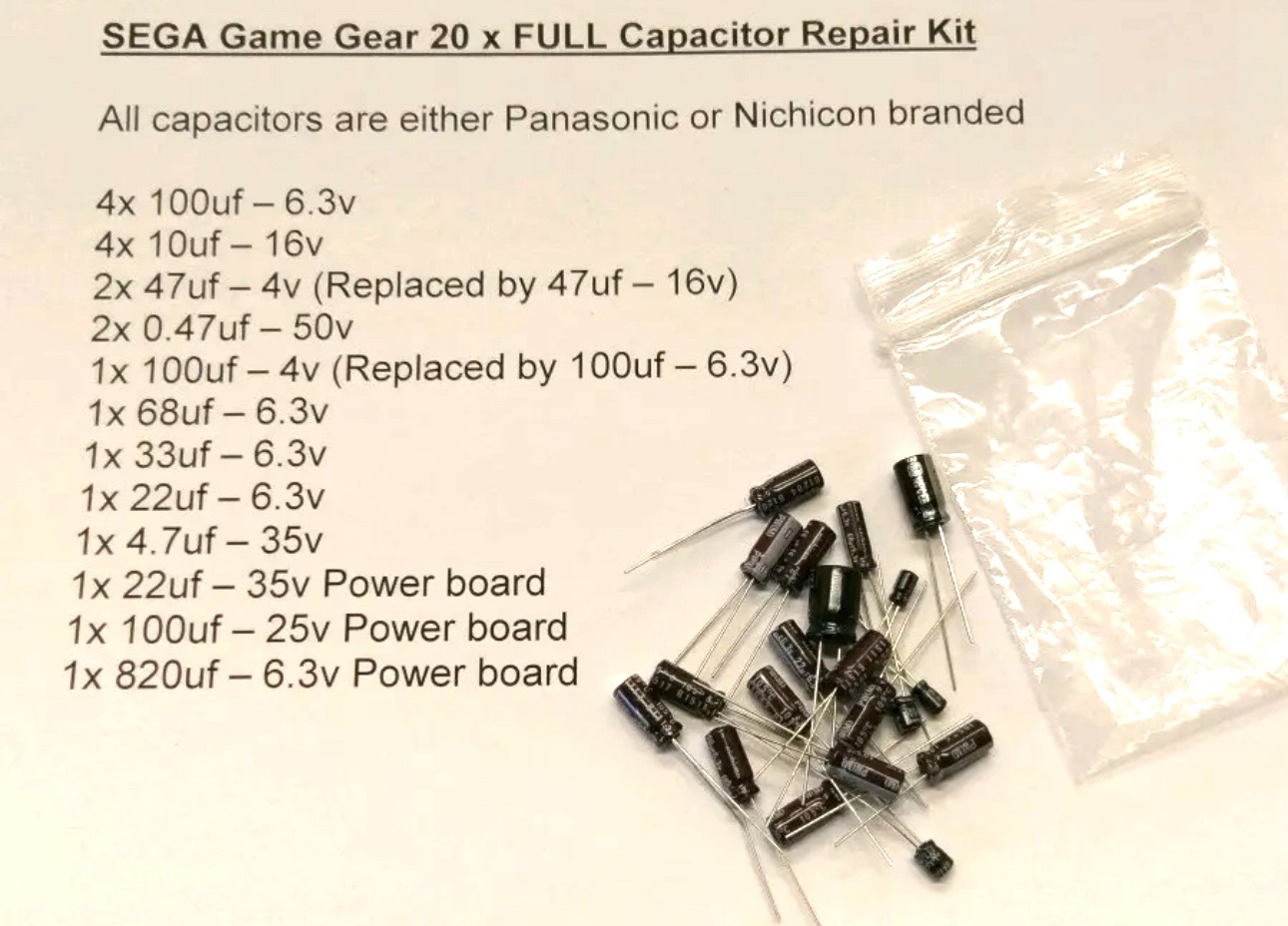
The first recommendation from anyone in the know is to change the caps before they start popping and corroding everything. I have a set of replacement caps ready in anticipation.
Full GG Cap replacement GG Cap replacement list
My hope is that this unit has not yet reached that corrosion stage….fingers crossed 🤞
Hurry along now Mr.Postman….
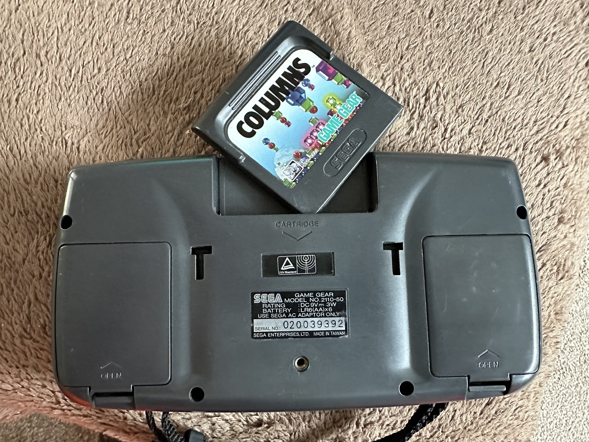
Both Game gear and replacement Caps have arrived. And I’m really happy as there is a game in the unit as well “Columns” Sega’s answer to Nintendos Tetris. A nice bonus.
Just minor scratches on lens areaBonus game received…NiceNice and clean
The unit turns on, there is no sound, and only a very feint green glow when the unit is held at an angle. It’s looking very much like it is the old Capacitor problem.
No sound. Powers on.Turns on and green glow
The unit is in surprisingly good order with scuffs and minor scratches as you expect from a game that’s around 30yrs old. The lens scuffs aren’t an issue as a new lens is relatively cheap. But that isn’t the problem as it stands. Let’s get it working and I can worry about that later in the repair process.
Clean battery compartment Another clean compartment
There are no signs of any corrosion in the battery compartments and this pleases me. I only hope that when the unit is opened there are no obvious signs of corrosion on the boards.
Wish me luck, I’m going in….
Overall I’m happy with the condition inside, no bad corrosion, however it’s noticeable that a few capacitors have leaked. The worst seems to be C39 on the main board, it’s easy to see the residue.
Main board Capacitor C39 leaking
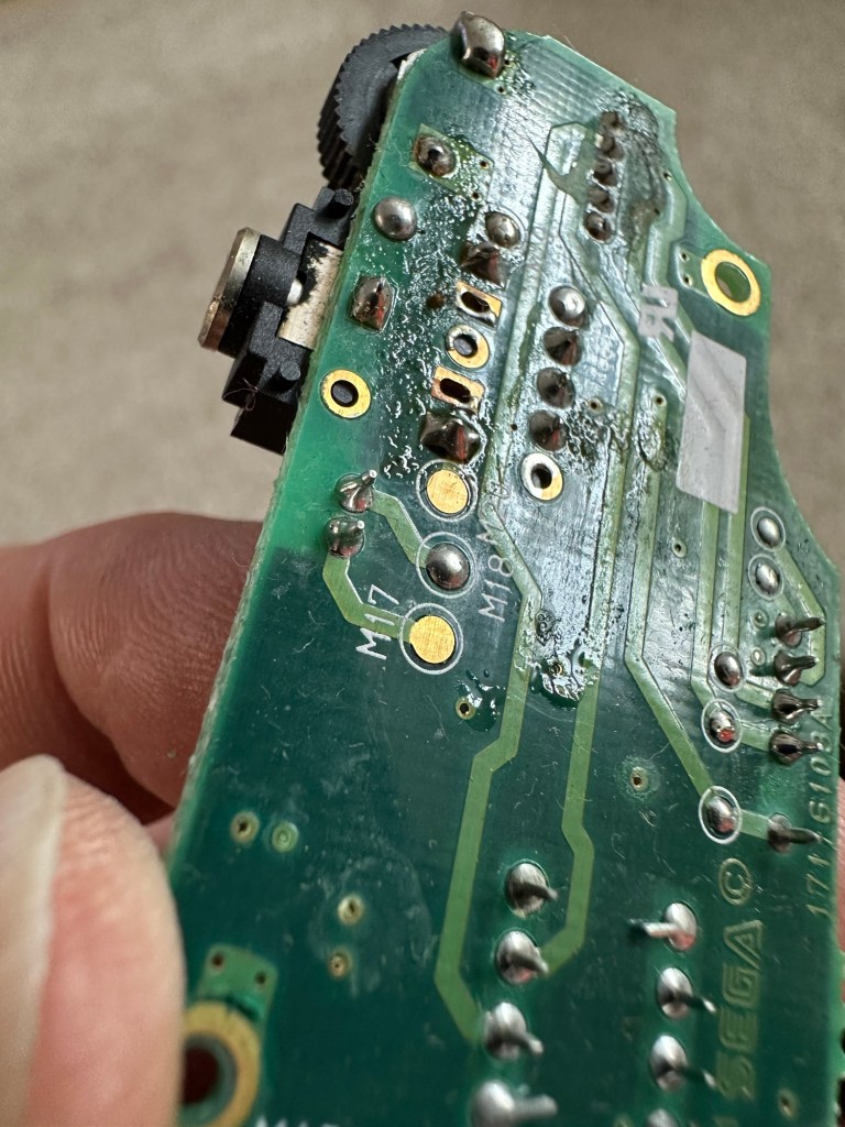
This unit separates into three boards. An audio board, a power board and the main board. This is a twin asic board, I have removed the audio and power boards as these are the first and possibly the easiest for me to be working on.
The audio board has 5 capacitors that require replacing, I can see some leakage on the rear of board but not in the area of the capacitors. I suspect that this is factory flux though I could be wrong. When I remove the caps I’ll clean all the pads and use IPA to clean so this should sort that issue out.
Audio board Leakage or Flux
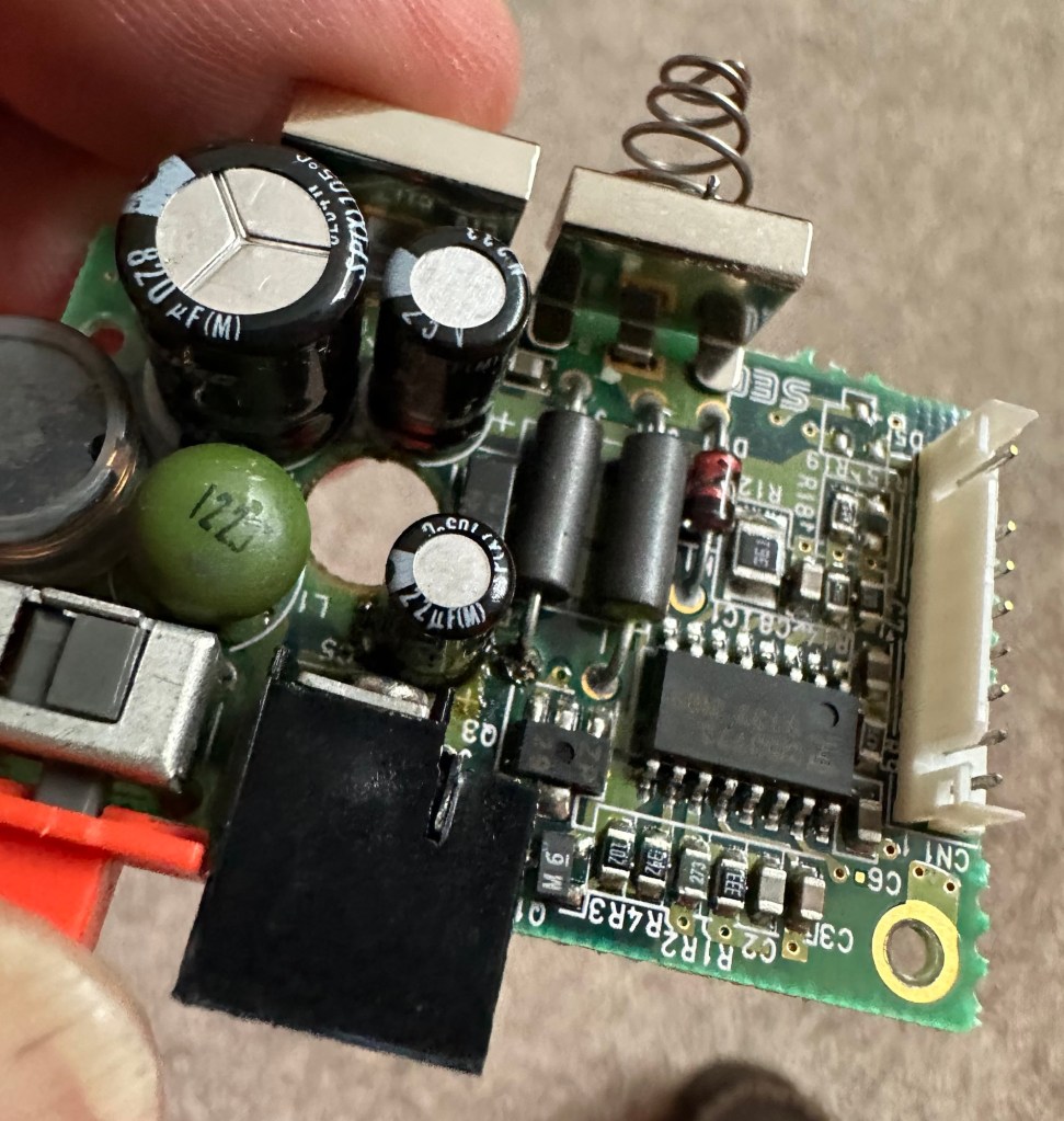
The power board only has three Capacitors that require changing, however it’s clear to see here that C5 has been leaking.
Powerboard C5 leakage
Let’s get on with the removal and replacement of these 8 components. The other 11 are on the main board.
Well that didn’t go too bad. A few minor position changes due to the capacitor types being a different size on the board compared to the 1990s version.
Old caps and newAudio board cap replacementAudio board now clean
It was obvious that there had been leakage on these two boards due to the fishy smell that arose when the soldering iron was used. That said, the old capacitors came off without too much problem. I used solder braid to remove the old solder and then gave a good clean of the board with IPA prior to re tinning the pads prior to putting the caps back in place.
I knew there wasn’t a big issue with the power board as this was sort of working prior to this project. This was the easiest board to solder as it had through the board components, pretty much a straight swap but for better components.
Power board with new capsPower board clean
The audio board was different as I had to reposition these pots so the case could close properly and the shielding could go back into place with no issues. Again I used the same process of unsoldering, cleaning thoroughly and then tinning the pads.
These two boards are now complete. As a test I thought I’d reassemble the unit and see if there was any improvement. Power came on and the red led lit, this was a good sign that there was power and I’d not messed anything up. Secondly there was sound, we didn’t have that before so this is a definite improvement on what we originally had. Volume works with just a couple of occasional crackles so I may have to use some more contact cleaner here.
We have sound
So far, so good. No real improvement to the picture even though you can see something is trying to come through. That said I’m hoping the replacement of the caps on the main board will help this. So with no further a do, let’s get the main board finished.
Just got home from work, now time to get these last 11 caps done. All the old ones removed, all the pads wicked to remove the old solder and what a stink of old fish, these capacitors had definitely died.
All old caps removedOld caps removed and area cleaned
All cleaned with some IPA to rid of all the debris and then fluxed and tinned the pads ready for the new capacitors to go into place, I’ve got this off to a tee now and these went on a lot quicker, easier and tidier than the last lot. I’m a lot more competent now, and feel more confident with this process.
New caps going into placeLast two new caps go into place
Had a little trouble getting it all back together, a couple of the new caps had to be tweaked slightly as they were in the way of a screw post, the earth shield was also causing issues and shorting the system, again a bit of captain tape helped shield an exposed component. All this done I put the strap back on and loaded up the batteries. Switched on and red light, all looking good…
All working
Very happy with the fix, that was my first Cap replacement and I’m happy with my first attempt. Again you learn from these attempts and the reluctance I initially experienced was just nerves. I’d be more than happy to do more of these fixes, maybe using the modern surface mount components next time.
ColumnsYou did it
Another one saved from landfill, I wonder how many of the 10.6 million more that were made of these have suffered that very fate. Scary.
Anyway, I’m looking at using this unit to do some mods, so this is going to be my test bed for other projects.
The radio was received earlier today. Cosmetically it is a bit tatty, batteries were placed into it and apart from a quick flash from the power light when it was switched on there was no sign of life. So the original description was false as it stated that it powered up with a very low volume. Oh well, not to worry, it now gives us something else to look at.
Tatty appearance
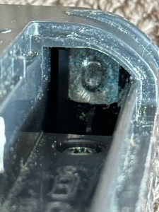
Looking in the battery compartment there looks to be corrosion, this seems to be a common problem with items I’m buying at the moment. The screws have all been tampered with so I suspect others have been inside this radio prior to my purchase, this could be interesting to see what’s already been tampered with or attempted.
Tatty appearance, non workingCorrosion….again
I’ve had the unit open and the first thing that comes to light is the utter filth inside. The speaker is thick with god knows what and the board and switches are also covered in the same filth. Before I do anything I’m going to get this cleaned up.
Filthy circuit boardDirt from speakerCorrosion
I’ve used IPA on the board and cover and on the (thankfully small) corrosion on the positive battery pole and this has cleaned up nice. I’ve used contact cleaner on all the switches and dials and these have also come up ok.
Speaker before cleanSpeaker after clean
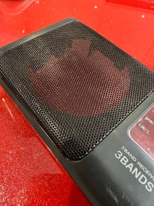
The speaker grill, I have tidied up and used permanent marker to get rid of the marks on this item. This has tidied it up really nicely.
Tatty appearance Grill after polish and touch up
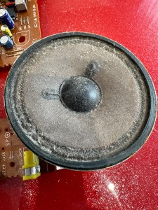
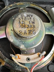
On the speaker I just used a dry cotton bud to wipe it over but I have my suspicions with this speaker, it looks quite worn and earlier reports on the lack and consistency of sound points to this being a potential issue with this unit. There are no clicks and pops when turning the unit on, there is a power and tuning light. Just no sound.
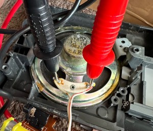
Speaker defective Multimeter to check speaker
The speaker is a 4 ohm 1w speaker, I’ve used a multimeter to check its operation and it’s showing as dead, not registering at all, it should be looking at indicating something within its 4 ohm range. I’ve double checked it by putting a battery across the terminals and there are no pops or clicks so this confirms things. I now need to source a new speaker.
Trying to source this speaker in the uk is a tad problematic. There are items available but I’m not paying out two to three times the value of the whole unit. I’m going to try some thrift shops to see if there are any suitable donor units available if not I’ll have to purchase a few of them from China, and that will still be cheaper than purchasing here in the UK, crazy isn’t it? But it’s a long wait….
I did manage to get one from the Uk. Paid about £5.18GBP and it should be here in a couple of days. The annoying thing is that the postage is almost the same cost as the actual speaker and that only cost £2.69GBP. Annoying though that is, it has to be done if we want to get this fixed.
New speaker Speaker placed
I couldn’t get a 1w 4 ohm speaker only a 1w 8 ohm speaker, this will be fine as at this level of use it will not affect output at all.
A small bit of desoldering, removal of the speaker clamp and the speaker comes away after a little persuasion. I take the opportunity to clean the board and all the battery contacts with some cleaner, and all corrosion marks and debris are now a thing of the past.
Corrosion cleaned
I put some contact adhesive on the speaker grill and put the new speaker in place, clamp is attached and I now solder the speaker wires back in place.
All screws back in place, new batteries in the rear and battery hat hatch closed, the unit looks good.
But does it work?
Radio works – have a listen
You betcha! Have a listen to the short video above to hear it as it should be.
I’m very pleased with this little project. Simple repair in the end but in my eyes it’s another item that isn’t going to landfill. And that’s a win for me, as it’s a nice little radio and I’m going to get some good use out of this.


You must be logged in to post a comment.