I recently purchased this camera and wrote about it in a previous blog entry Werra 1
I’ve commenced taking the Werra to pieces. The winder was not working and the shutter was not firing. Before starting this work I’ve viewed this page at Everything Vintage where they have recently carried out a full strip down of the Werra and you can view the page HERE, it’s all great advice.
Getting below the top plate was relatively easy exposing the mechanics from 58 years ago, I don’t think it’s ever been opened in all this time. I always love to see the ingenuity that went into these old cameras in years gone by.
Werra 1 stripdown
The internals look dirty in the photo but to be truthful I don’t think the lighting is doing it any justice, yep there is a fine oxidation coating but it’s at a very acceptable level considering its age. When I get to the point of dismantling as much as I can, I will start to clean and lubricate these pieces. But at the moment my goal is getting to the shutter.
Werra winding system – shutter not working
In the video above I’ve managed to get the shutter cocking using the lens ring, however the shutter actuator does work intermittently, but there is no movement of the shutter (Or is there…)
The only reason I ask the question above is that after reading the “Everything Vintage” link in the first paragraph it appears there is a second shutter that closes the light path to the film back when you wind on. When you are ready to expose the film this shutter opens and then there is a second shutter that controls the exposure. if you watch the small video above I think it is this shutter you can hear when I wind the camera on. Hopefully this one is working, I just need to get the one on the rear working, and for this I need to remove the lens from the housing. To do this I need a tool I don’t currently have but have now ordered. More to follow when the lens ring removal tool arrives.
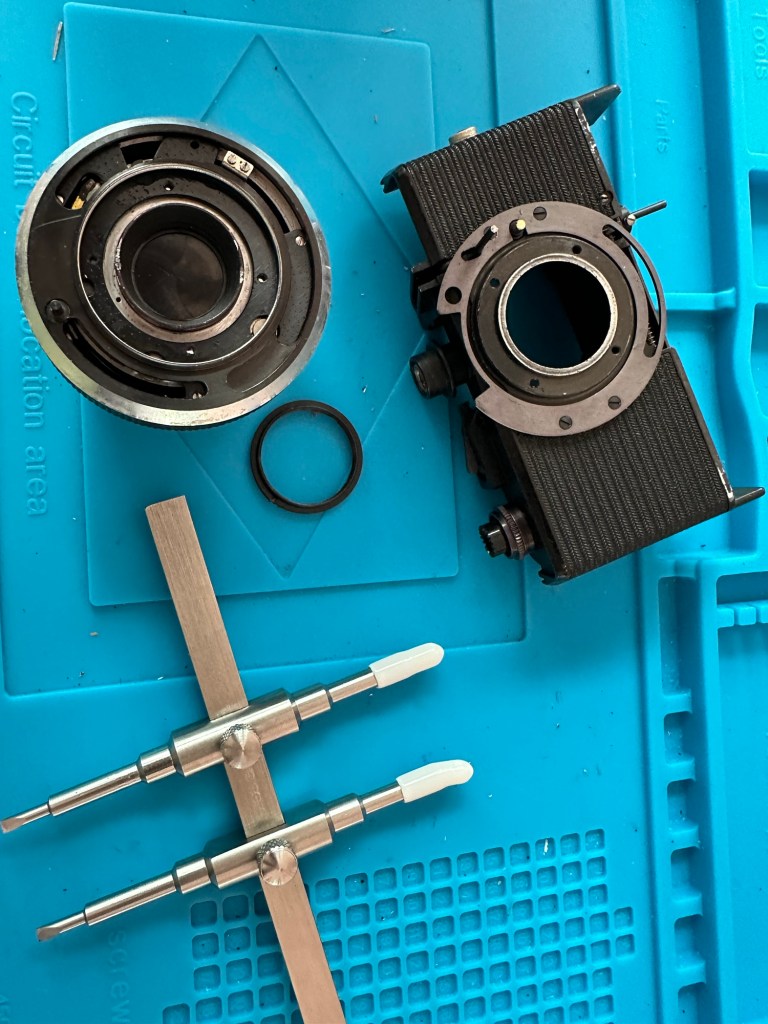
Lens ring spanner
The lens ring spanner has arrived, the ring is being right stubborn at the moment and Im struggling to release it from its 58 years of rigidity. I’m tired as well and don’t want to cause any damage to the shutter so I’ll come back to this later.
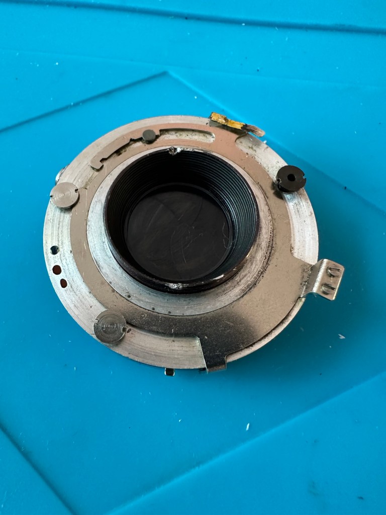
18 hrs later, I’m rested and have another go at releasing that lens ring, this time I’m successful and I manage to release it. Sometimes it’s better to sleep on a problem and approach it with fresh eyes rather than continuing whilst tired and prone to making mistakes.
Werra Lens ring removed
With the lens off the body, the shutter cassette can now be removed. It amazes me just how intricate this cassette is and the workmanship that must have gone into it. I’d estimate at least 10 small cogs and a number of tiny springs with levers and pivot points, amazing really considering it’s about 60 years old. It’s amazing how modern technology has advanced.
Werra lens breakdownWerra shutter moduleWerra lens – another shutter on the rear
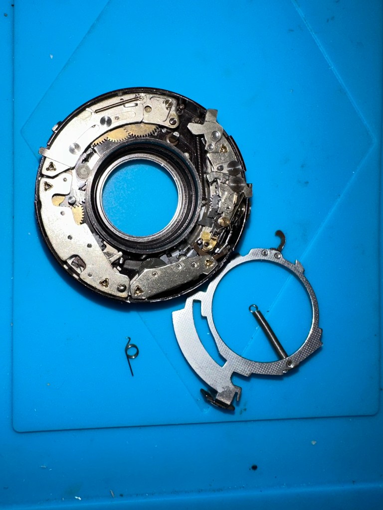
It takes some time getting into the shutter cassette as there are springs and things flying off everywhere, you really do have to photograph everything you do just to be able to check what goes where and how.
Inside mechanism – where is that spring from?Complexity of the shutter mechanism
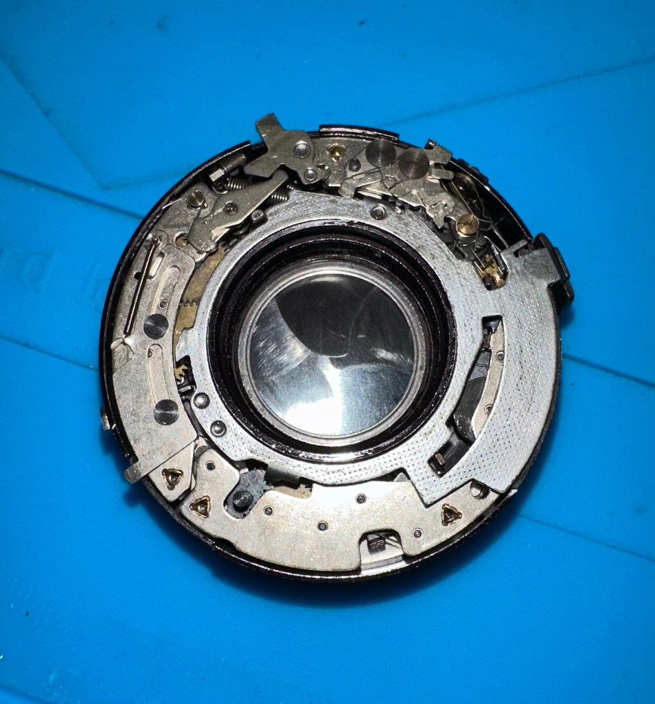
The shutter itself is rather clean apart from some fingerprints on the shutter leaves that must have been from years ago. I have cleaned this down with IPA and then used some finely ground carbon (pencil lead) as a dry lubricant and this has got the shutter moving just fine.
Werra shutter after being lubricated with carbon
I’m now starting to reassemble the lens and shutter as I’m happy that there is nothing else restricting the shutter and it is now moving quite freely. I will clean the camera as I progress and put some watch lubricant on the mechanics that are external to the lens and shutter assembly.
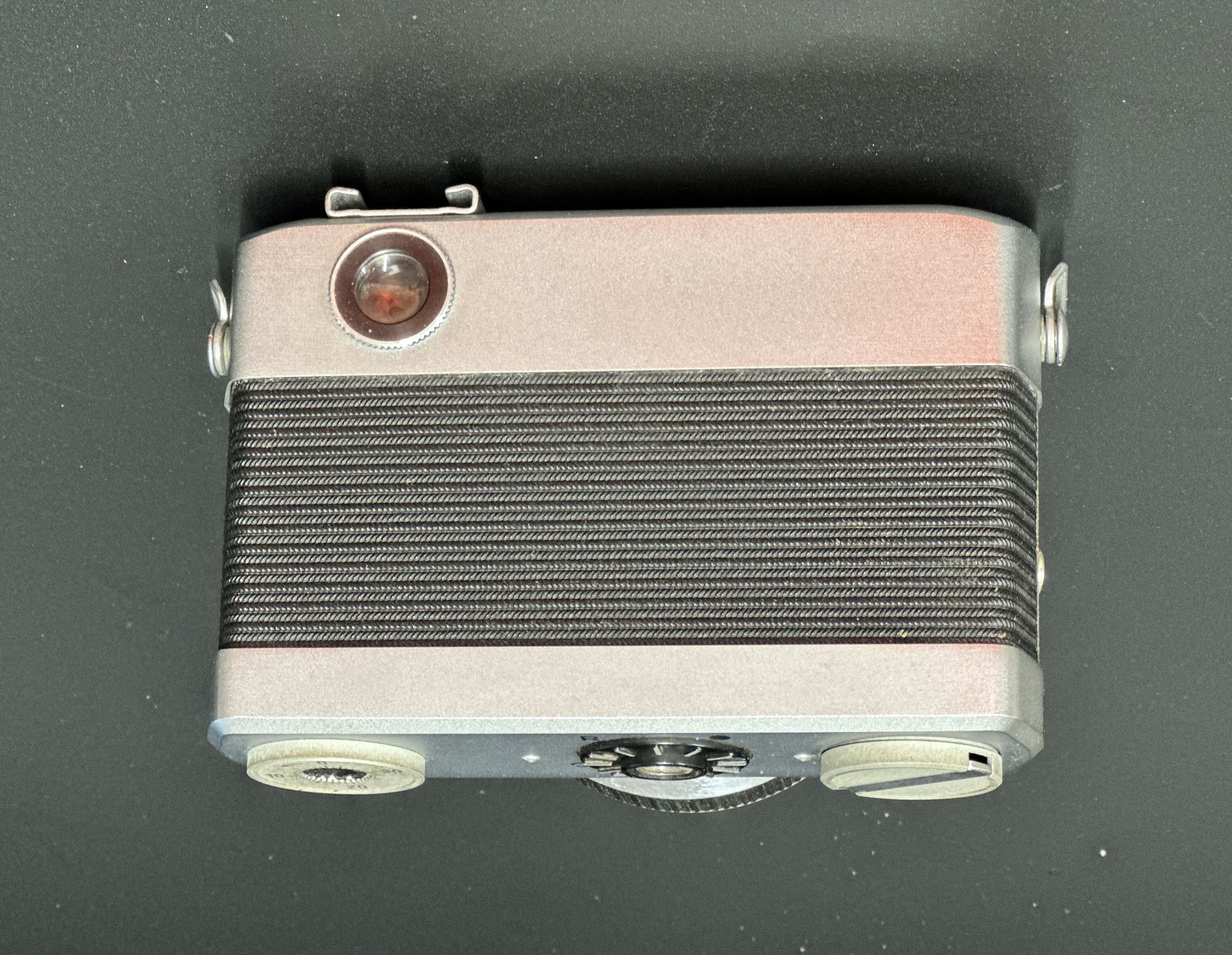
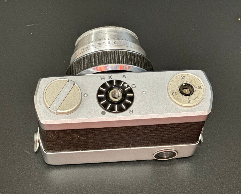
Werra 1 rearWerra 1 baseWerra 1 topWerra 1 front
Well it’s all been reassembled and is now back in one piece. It looks good, the shutter works fine and I’ve now vacuum packed it to go back into storage. I won’t be firing up a roll of film on it yet as I don’t have the time to did so at the moment. I’ll probably save that until the summertime when the weather is more favourable. I’ve really enjoyed this restoration even though at times it was very frustrating. This rebuild has taught me patience, or at least that I need to have more patience and just take my time. Intricate jobs on such old equipment need a clear head and a lot of concentration. I’ve learned my lesson and will endeavour to remedy that situation in my future dealings with such equipment.
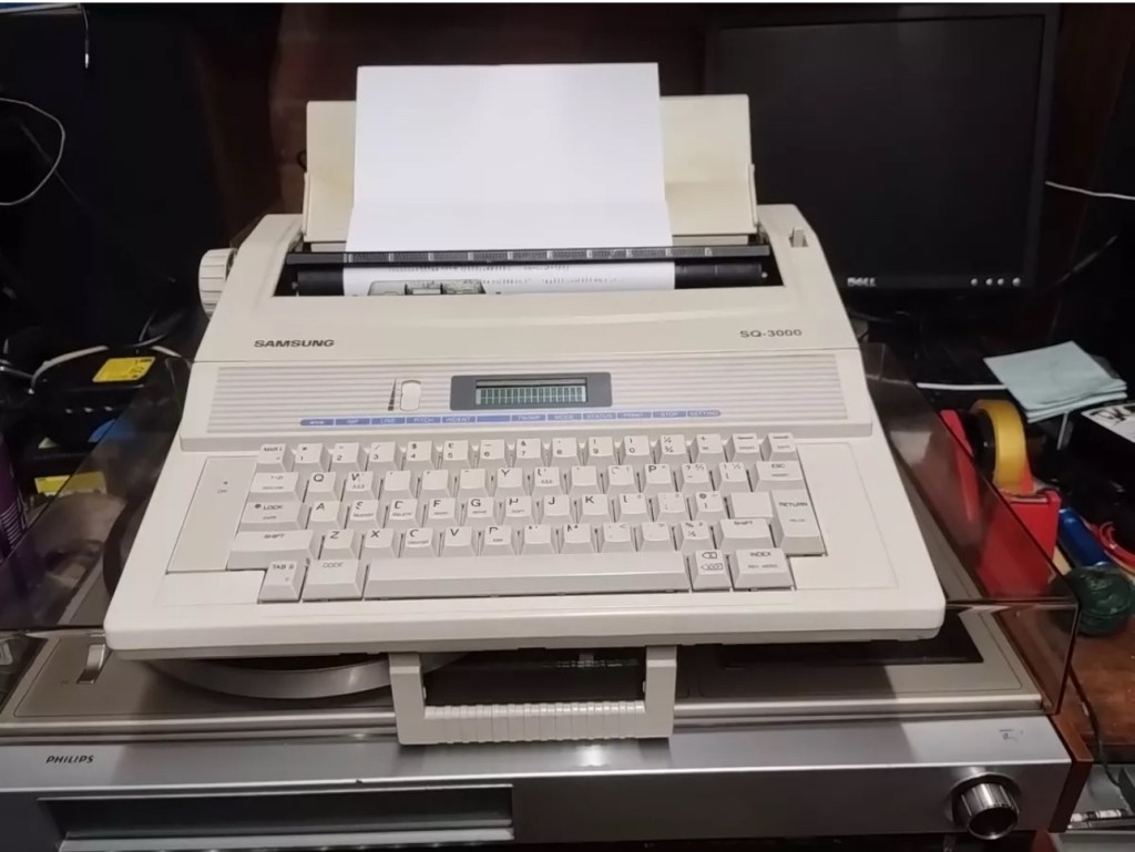
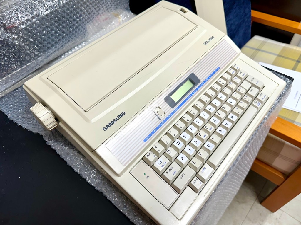
This is the follow up to a recently obtained electronic typewriter that was purchased in January 2025, the initial post can be found here: Samsung SQ3000 electronic typewriter.
Samsung SQ3000 electronic typewriter
The following post will deal with the assessment on its arrival and what I am going to try to do, to get it back working again, as close as possible to its original state.
I’ve downloaded an instruction I manual, I’ve had to download one for a Smith Corona Wordsmith 200, it is in theory the exact same unit, just under a different manufacturers branding.
Assessment
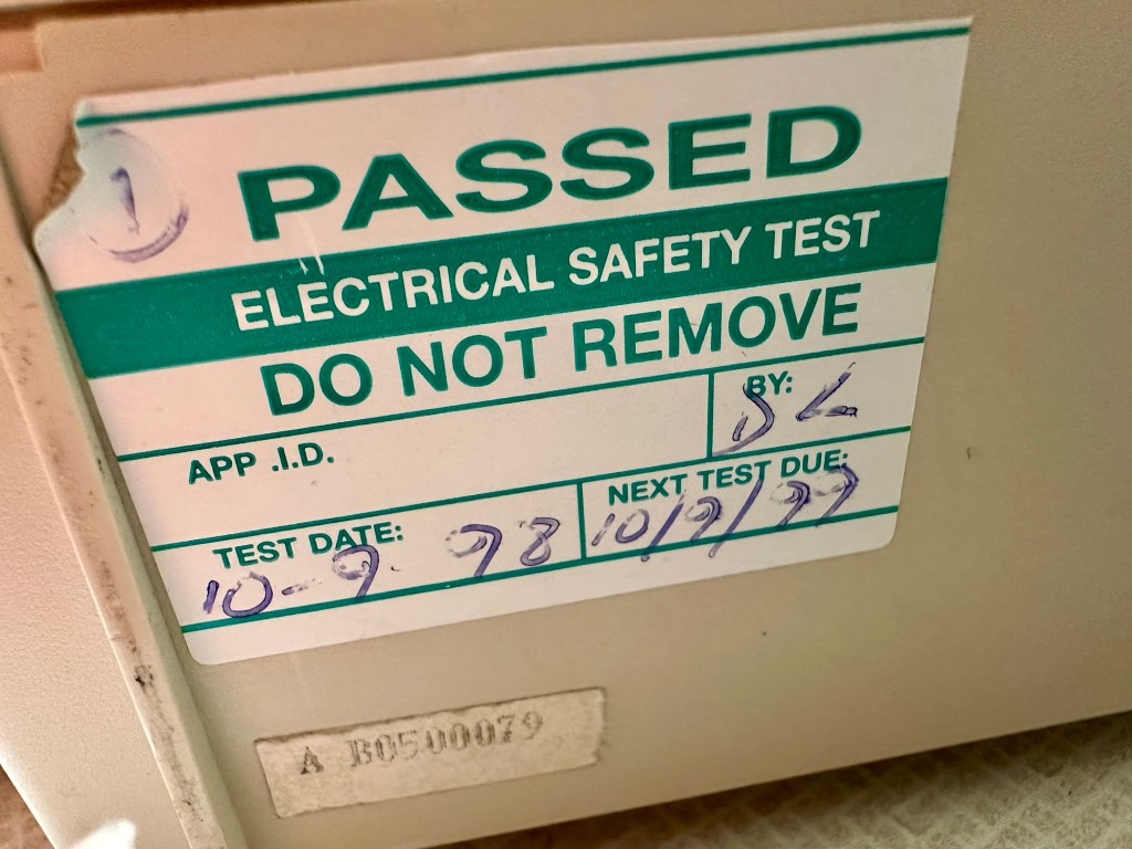
It’s arrived and apart from a little age yellowing it looks ok. There is a PAT testing sticker that says it was last electrically tested back in 1998 and is due a retest in 1999. This corresponds with my date estimate of mid 90s.
Yellowing Pat test date
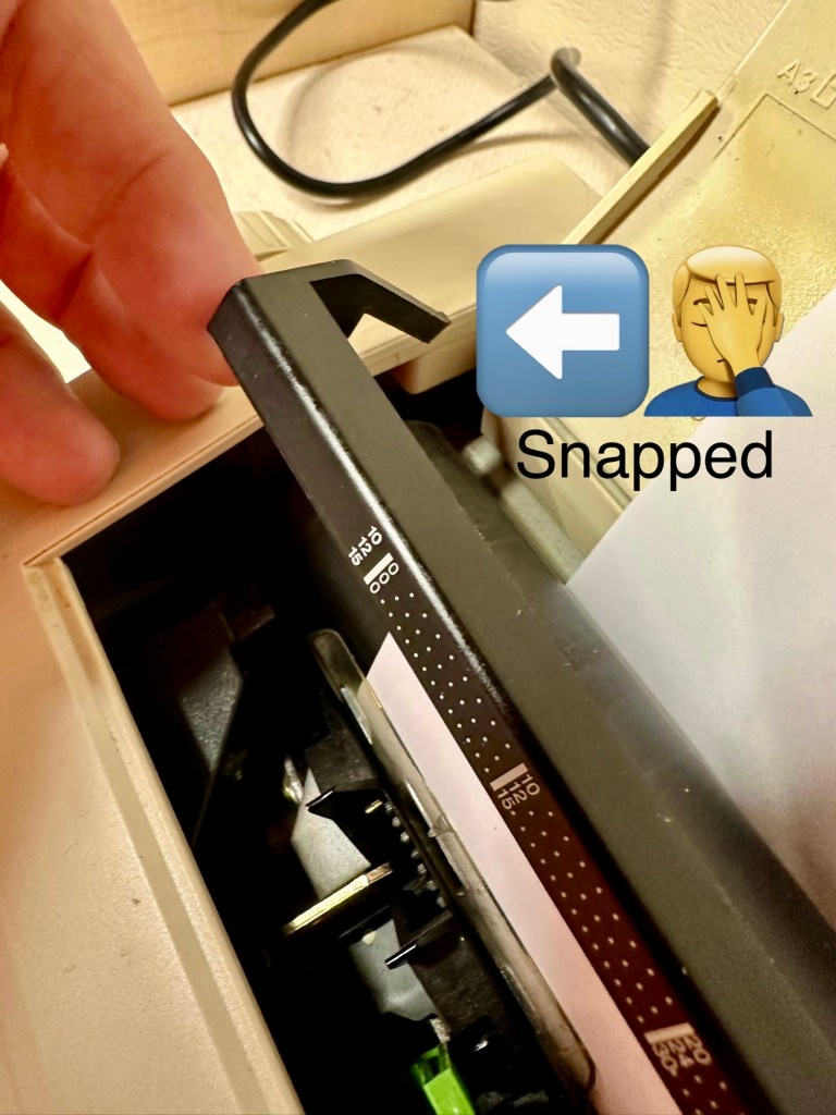
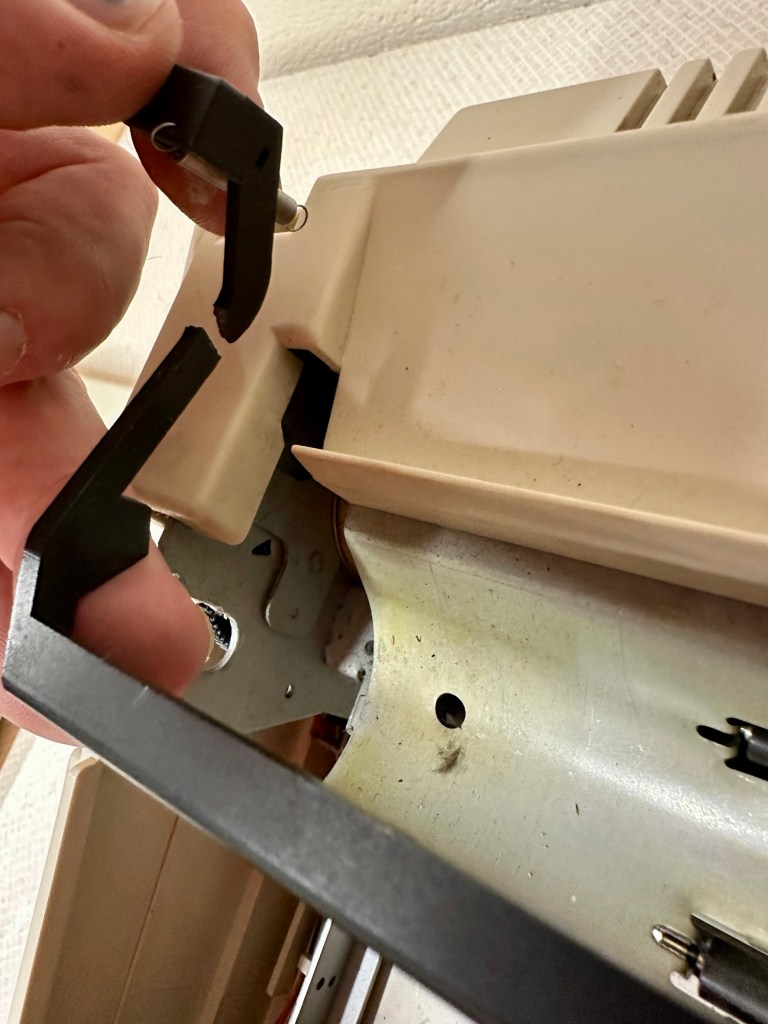
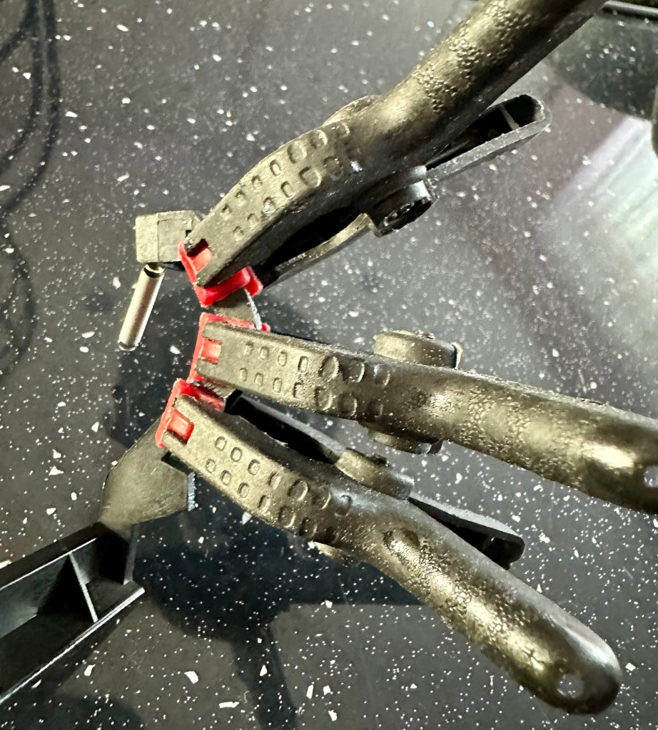
I will retest and renew the safety checks when I’m finished working on it. I have noticed that the paper bail/release rail is broken on the left hand side so I will have to add that to the repairs, this shouldn’t be a major concern.
Paper bail snappedBroken piece recovered
Before I took the roller out to get to the paper bail I did start the machine up. Everything went as expected and when I tried to type I was getting some weird reactions to the keys I was pushing. All kinds of characters were appearing.
Before
I checked the daisy wheel and there was a click. It wasn’t sitting right. I reset the machine using the two reset buttons and the machine then went through its reset programme, pretty much the same effect as turning it off and on again. (Not much changes in the way of tech there then)
After
Well that’s worked fine, I have tried every combination on the keyboard including the erase function and this is now fully working. It really was quite simple. My next job is to try and fix this paper bail.
Paper bail removed for fixing
There is quite a bit of dust and dirt inside that needs removing. And whilst I’m at it I will lightly re grease the areas that need it. Let’s be honest it’s not been done in the last 30yrs so now is as good a time as any. Inside will get a light hoovering and a bit of a tart up, I’m not going to go mad. I will clean the outside and all knobs and buttons and try to get rid of some of the yellowing, but to be honest as long as it’s clean I’m not too worried about age marks.
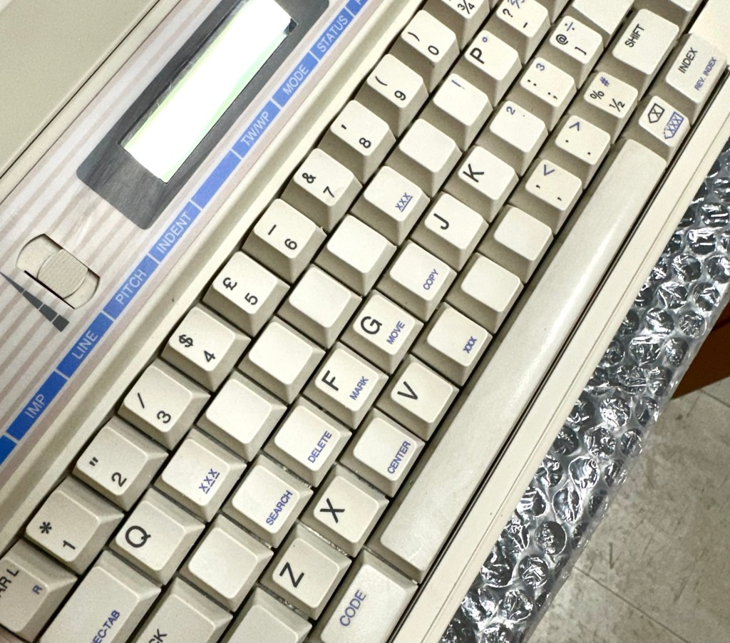
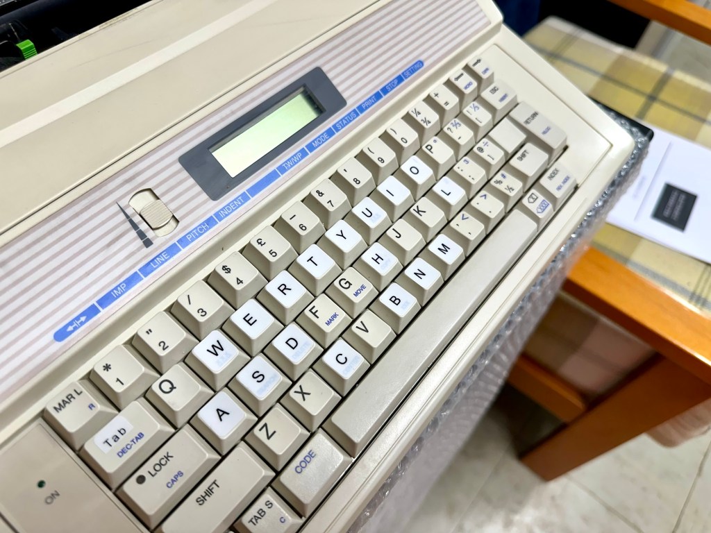
The keyboard has lost a few of its letters. I will remove what is left of some of them and use some keyboard decals to replace the missing ones. This will be one of the last jobs I do.
Characters missingKeyboard
Well that’s the assessment done and apart from a few small issues and requiring some basic maintenance I don’t think we have an immense amount of work to carry out. We know it now works. Let’s hope I don’t cause any further carnage whilst working on it.
Let’s get to work.
Repair
Right it’s straight onto the paper bail to try and fix the snapped end. Firstly I’m just going to use some superglue to get it in place. When this is dry I’m going to create two “Doublers”, place one either side of the damaged part and glue these in place to create a stronger repair and to add some stability to this area.
I’ve got some black semi rigid plastic. I’ve created a small template from a tracing that I did of the good right hand side of the bail.
PlasticTemplate
I now have two doublers cut from the plastic that I will use as explained above.
Two doublers
It doesn’t matter that they are not perfectly shaped, however they both fit perfectly well into the profile of the bail arm, and this portion of the arm is hidden in the typewriter housing anyway, so the part will not be visible, but it will now be strong.
SupergluedDoublers in place and clamped
The Doublers have been put in place using a quick set epoxy resin, I will leave this to dry for a good few hours before I tidy it up, with a light clean, and then I will try to get it back in place.
Bail arm repaired, installed and working.
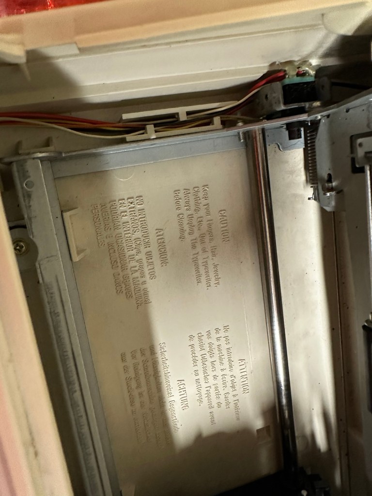
Now that’s done i’ve gone inside and there were a nice couple of spider webs around the transformer that are now history. I’ve secured the cable in the rear of the unit that never had any tension restraint, so that there will be no issues, should anyone now give a good yank on the cable lead. This is a safety addition I have made that was never on the original unit.
Cable restraint screwed to base to prevent strain on internal wires in and around the transformer bay.
I have also tightened all screws and checked the wiring and this all seems ok. Plug and fuse have been checked and all is looking good. I’ll carry out a PAT test once I’ve finished the clean up.
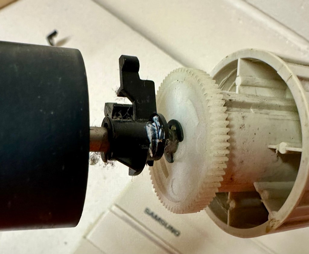
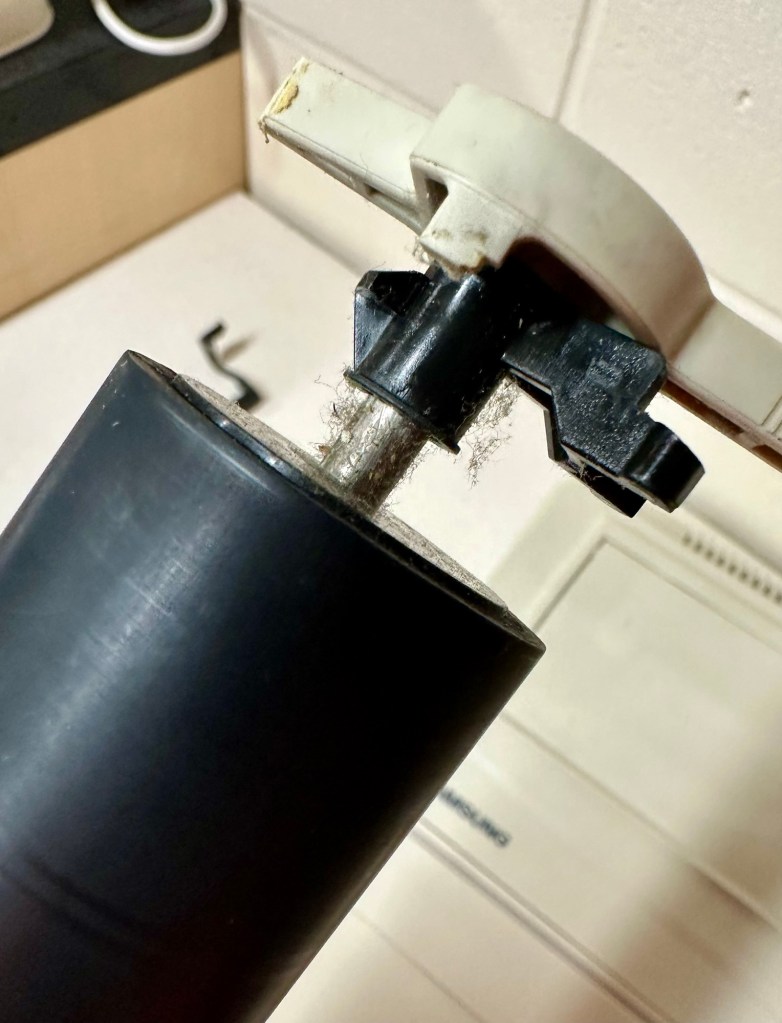
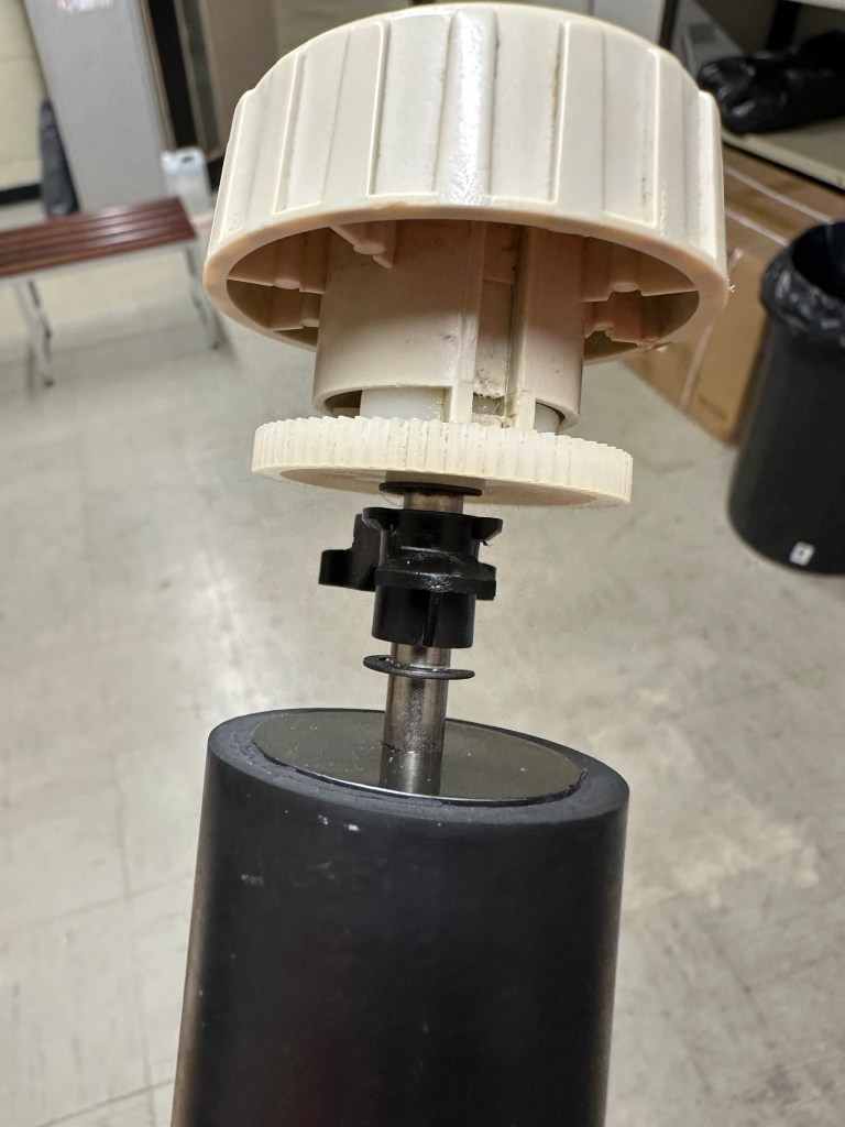
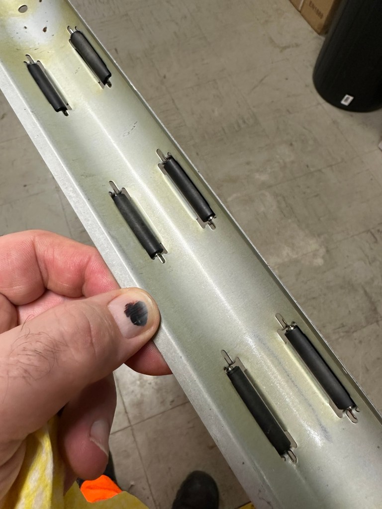
Roller cleaned and degreased Platten switch cleaned
I’ve cleaned the main roller with alcohol, and removed all the old grease and dirt from the platten adjuster switch and the roller advance knob. I have removed the platten plate as well as the six mini rollers that are here. I’ve cleaned them all and re assembled/installed them.
Platten platePlatten rollerRollers installed and platten complete
I have cleaned the daisy wheel as well as in and around the printing head unit.
Clean insideDegreased
Inside the unit I have given a good hoover as well as a light clean and again removed more old grease. I have given the exterior plastic a preliminary polish, this has removed some of the yellowing and made it look “cleaner” I am not going to worry too much about the yellowing as it isn’t that bad, and I don’t really want to venture into carrying out a “Retrobrite” on this unit. It would take too long and there would be no benefit for this project.
I’ve now added very small amounts of a watch lubricant to those areas that i have previously cleaned and removed the old grease from.
Light lubricantMain transport lightly lubricated
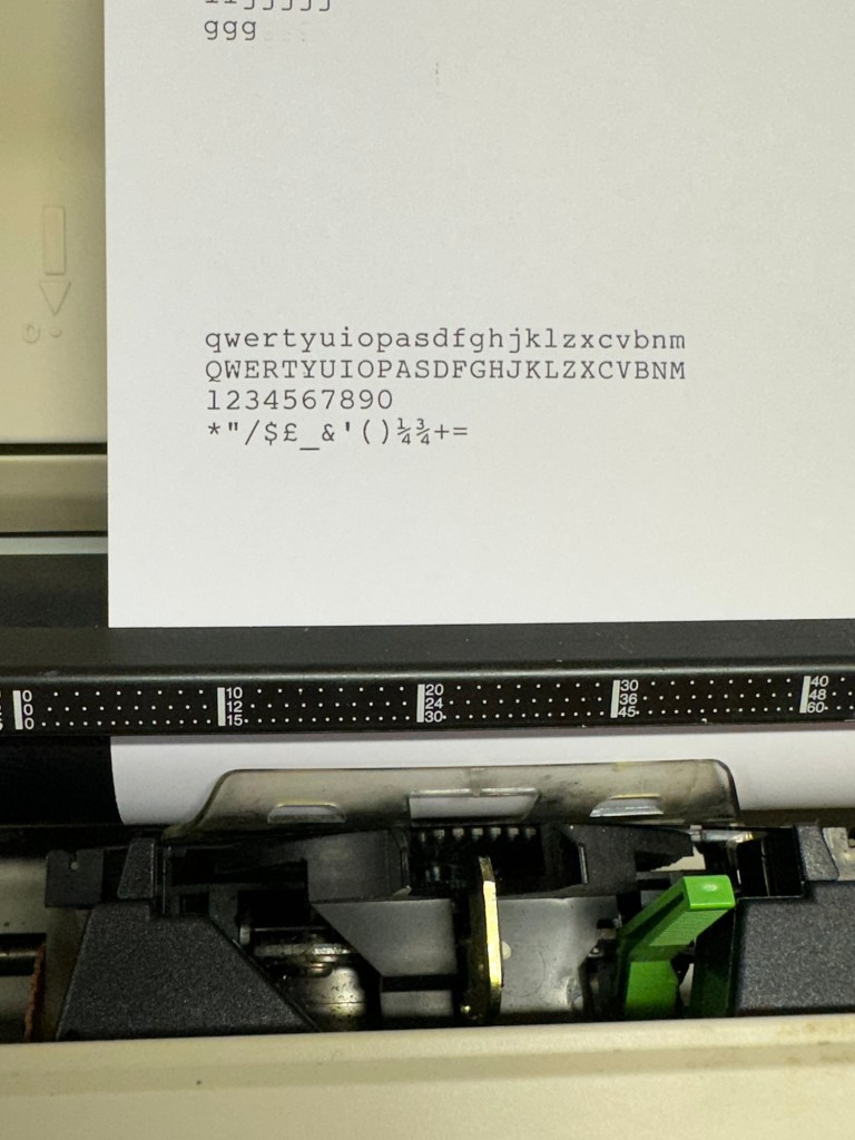
The unit has been reassembled and I’m pleased to say it is still working fine. It’s running smoothly and all aspects of the unit seem to be working just fine. To be honest it seems to be printing clearer to me.
Daisy wheel and print quality is perfect
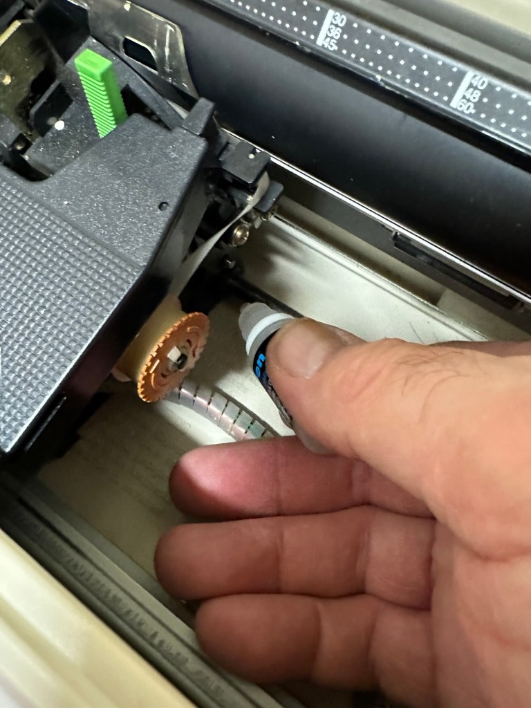
I don’t know how long the print cartridge has been installed but I suspect it may have been a few years back. It’s almost finished, and I do have a replacement on order. I’m sure a fresh cartridge will make the print stand out even more.
Next I’m going to have a go at replacing some, or even all of the keyboard letters. It all depends how it looks when I start replacing them. I’m going to gently rub off the lettering that is left and clean the keys using a 95% pure Isopropyl alcohol solution (IPA).
All damaged and missing key decals removed in preparation for replacement new decals. Others may have to be removed dependant on how the new ones look when in place.
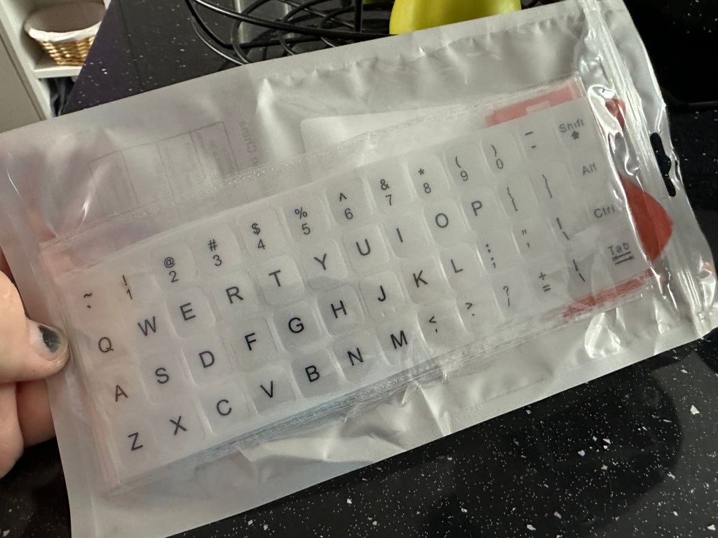
These are the replacement key decals I will be attempting to use.
Qwerty keyboard decals
I’ve replaced the damaged key decals. The ones I’ve used are a lot brighter than the original ones and really accentuate the yellowing. I’m not troubled by this as it keeps its “Old” look. I would have to scrape and wipe for hours to remove all the other keys and to be honest it would look just like someone had gone abroad to have a bright white set of dodgy veneers installed, it would look quite out of place, and in your face. Just like a Cheshire Cat smile.
New veneers anyone?
It serves a purpose and just allows the unit to be usable again.
The final product:
Looking damned fine if I say so myself
Fortunately a lot of the equipment and parts I have used, I was already in possession of, so there are no additional costs for this project. Below you can view the total costings for this project as they currently stand:
Purchase inc postage £13.14
Cable restraint £0.25
Keyboard decals £1.25
Total cost of project £14.64
Again I have managed to save a fantastic 90s retro item from landfill for very little cost, and that is a fantastic result. It has years of use left in it, as long as the consumables remain available, and of that I am confident that they will be available, for at least the next few years. The unit is clean, I’ve just carried out an electrical PAT test and it is electrically sound.
Believe it or not I’m going to go back in time and will write some traditional typewritten letters to friends and family. I’m looking forward to doing that and it will certainly surprise them, it will be totally unexpected.
When all that is done, i will donate this unit to our local LOROS Hospice shop so they can sell it on and raise much needed funds. They deserve it. Edit: This was done in March 2025 at their shop in Hamilton Leicester. I hope it gets them a good price.
Watch the brief video for the final words on this restoration. All 13 seconds of it.


You must be logged in to post a comment.