Sinclair Cambridge Memory Calculator

What the listing stated:

This auction is for a used cased Sinclair Cambridge Memory pocket calculator and original case. The item is in very good cosmetic condition as is the case which still has its instruction sheet. The item is powered with 4 x AAA batteries (not supplied) and does work although 1 of the digits is faulty and does not display (see pictures) plus the number 5 digit is not working. Please refer to the pictures and description provided before bidding.

EBay

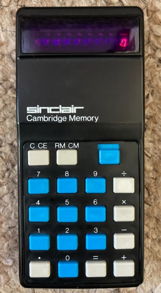
So it does work, but it doesn’t? This calculator is a model one memory calculator, that dates from around July 1973, ( Actually May 1975 see photos below) and is one of the earliest available mass produced electronic calculators available in the UK at the time. And it was produced in collaboration with a guy called (Sir) Clive Sinclair, who in the following decade would become synonymous with tech development in the UK. It retailed at £29:95GBP, and given the rate of inflation, its cost today in 2025 would be a staggering £463GBP. Wow!

Courtesy of Vintagecalculators.com

I love collecting old calculators, I couldn’t afford one back in the day when they arrived on the scene as I was only a child and probably only on about 20 pence a week pocket money, and savings and investments were not even known to me at this period of my life. The thought of saving that precious 20p a week for the next 150 weeks wouldn’t have even remotely crossed my mind. What no sweeties?

But I can buy them now, so no big issue!

So this one has become available, and I’ve been tracking it for a week or so, there were nine other people watching but I secured it for a total including postage of £14:49GBP, and I’m happy with that, it’s a piece of retro history for a very good price. Even if it remains faulty, or should I say working but not working?

This unit obviously has its problems, the button number 5 doesn’t work and one of the led digits is also not functioning. Hopefully I can get these issues sorted and soon have the calculator back up and working as it should. That would be nice. I’m looking forward to this little project.

Assessment:

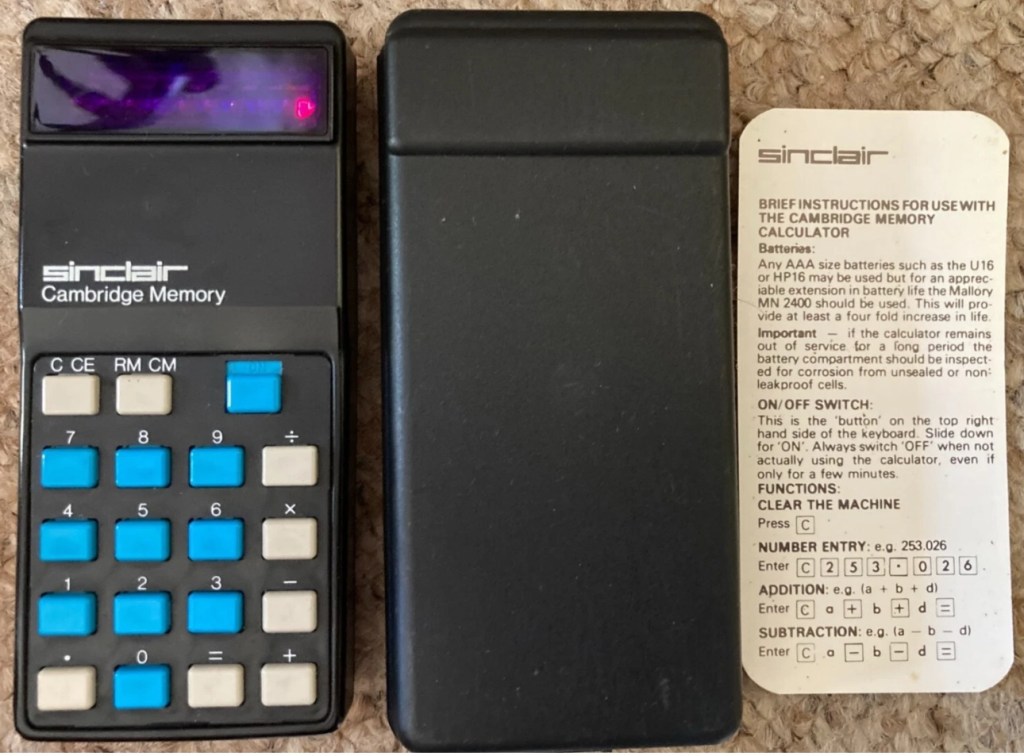
It’s arrived and it’s a lot smaller than I anticipated. It has a separate hard protective case, which is a nice touch and a small info sheet on its operation. Cosmetically it’s in a good condition with just minor signs that are age related. There are no gouges or scars so it has been treated well, though it’s not pristine.

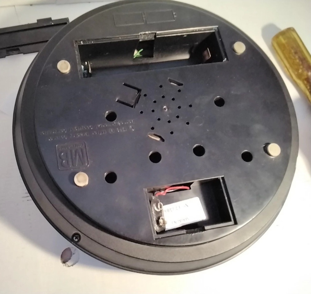
Batteries go in ok but, I believe old style AAA batteries were a little wider than those used today and would sit a bit more snuggly in the battery compartment. As you can see there is a little wriggle room here, and springs at both ends need adjusting to help prevent this. I may have to use some spacers so the batteries sit tighter in place.

Gaps between batteries – means movement

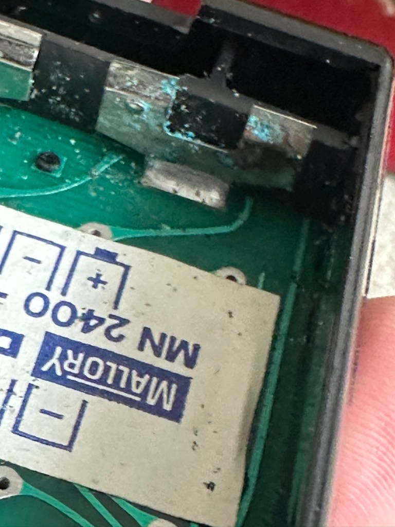
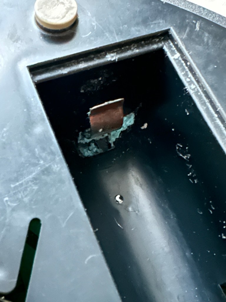
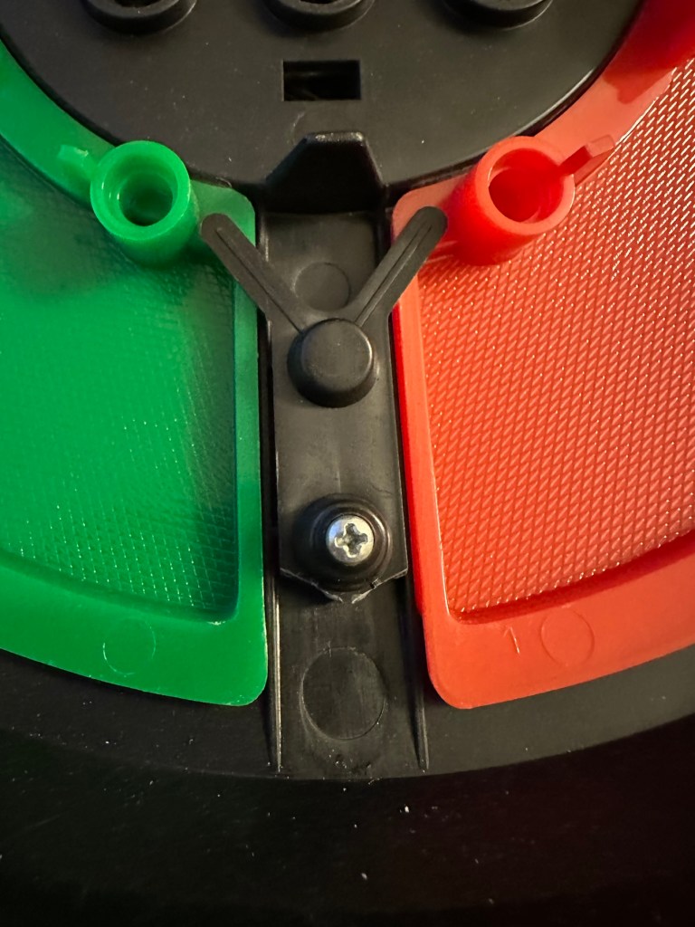
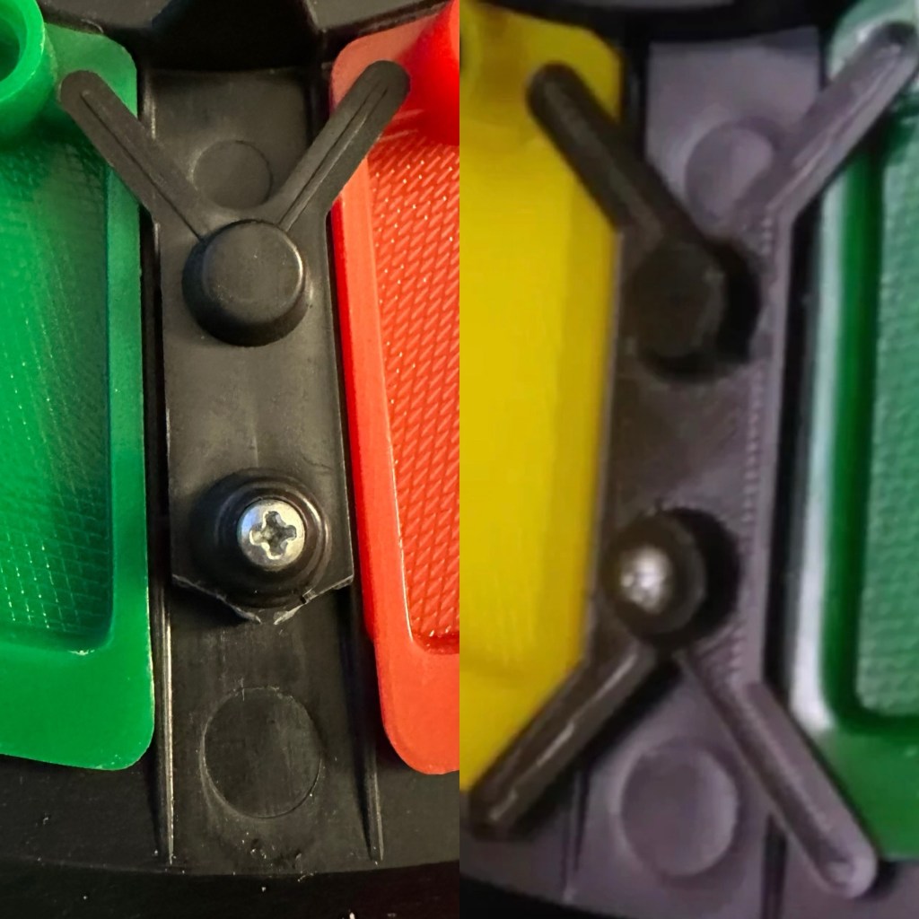
The switch is a bit temperamental and can be seen quite plainly from the battery compartment. It looks strangely out of place with no batteries in place.

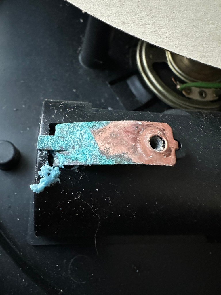
It is such a basic design solely relying on tension of a small metal plate to short across the connection points. Should be a simple enough issue to sort.

There is a little battery contamination on one of the battery contacts, again this shouldn’t be too much of an issue and should clean up ok with some IPA.

Some battery contamination

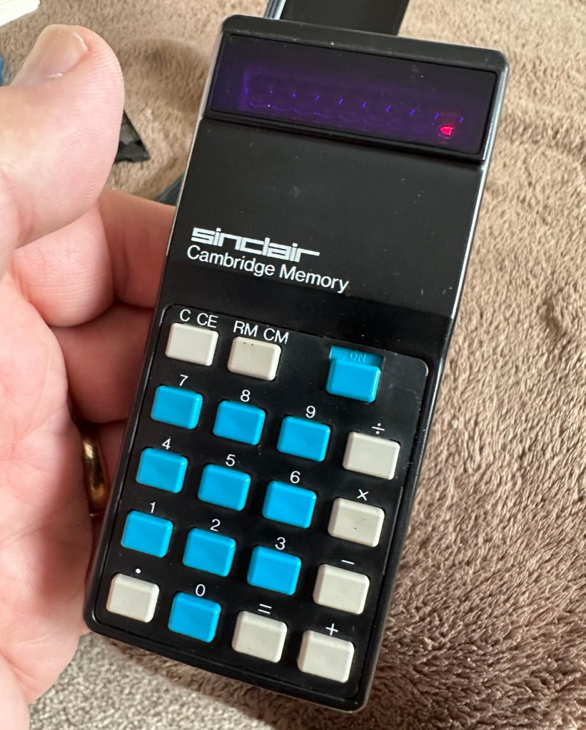
It was originally reported that there was one unresponsive button this being the number “5”, there is also another unresponsive button, the multiplication “X” button. There is also one LED indicator, the 4th one in from the left hand side that is not operating. Add to this the issue with the On/Off switch and the contamination, and the original faults reported in the original sales pitch have now doubled. I just wish people would spend more time going over the issues and then give actual accurate feedback as to what the real faults are, it would make for a far more pleasant buying experience. Rant over.

There doesn’t seem to be a single screw holding the body together, I just hope it isn’t all heat welded.

Let’s try to get inside.

Repair:

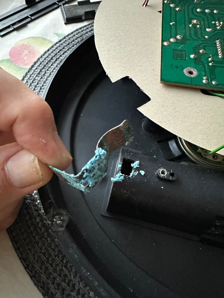
Well it cracked open quite nicely with no issues with just a plastic flat prise tool. The main board just sat comfortably in the unit, secure, and not a screw in sight. Strange as time moves on some of the games units I come across have best part of fifty of the little blighters to remove before you get anywhere. sometimes the old way is good.

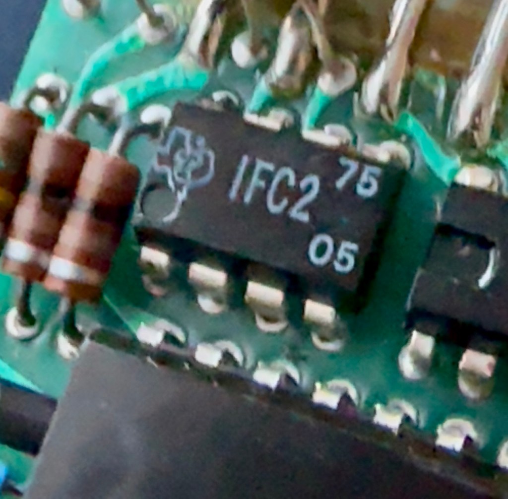
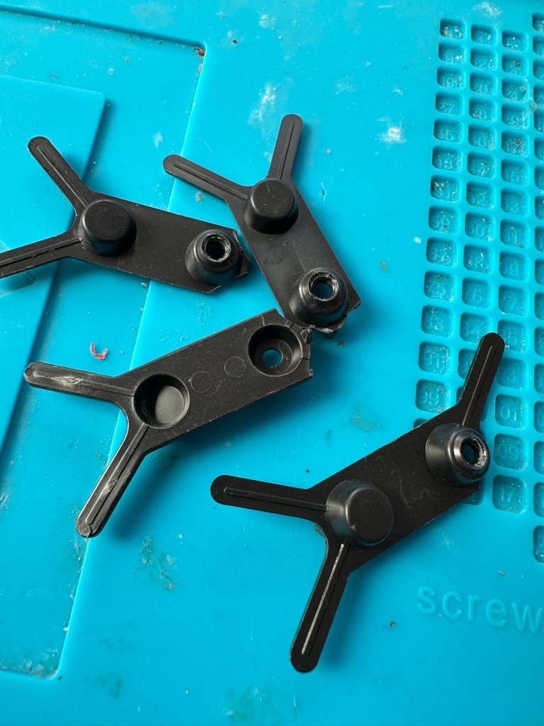
The dismantling of the keyboard is a little complex and you have to take time and make sure you know how it’s going to go back together, it’s just a bit fiddly. The board is quite straightforward and as soon as I see some of the IC’s it dates the unit perfectly. The chips are dated May 1975, and that is about 18 months younger than what I originally thought, it’s quite informative to get inside and learn occasionally and this is just as good as having a birth certificate presented to you. All good stuff.

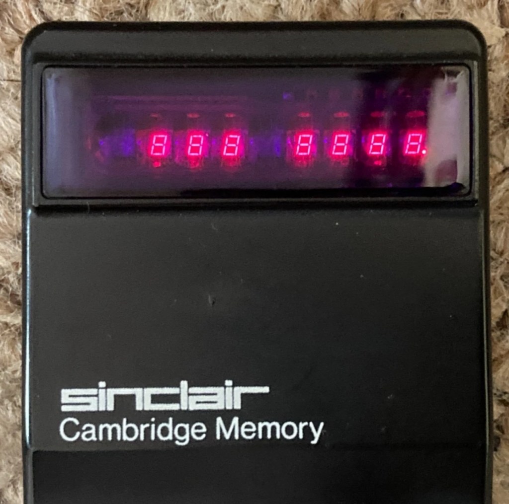
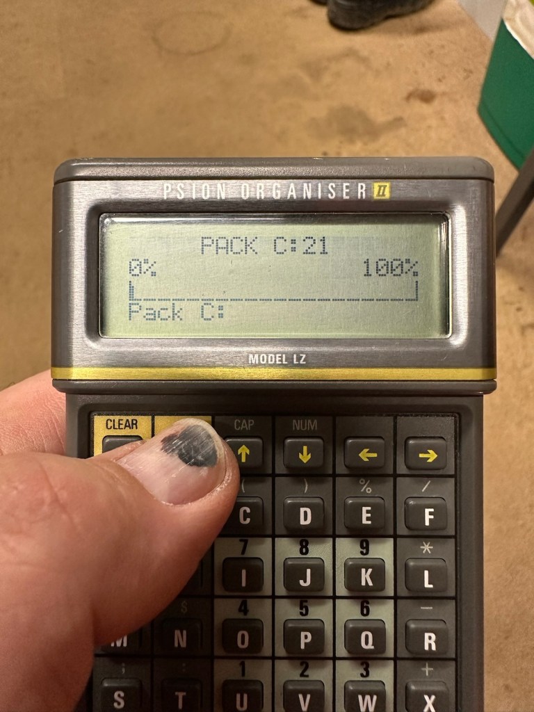
I’ve proved that there isn’t a problem with the missing digit on the display as using my multimeter in diode mode I am able to prove that this LED is working fine.

LED working

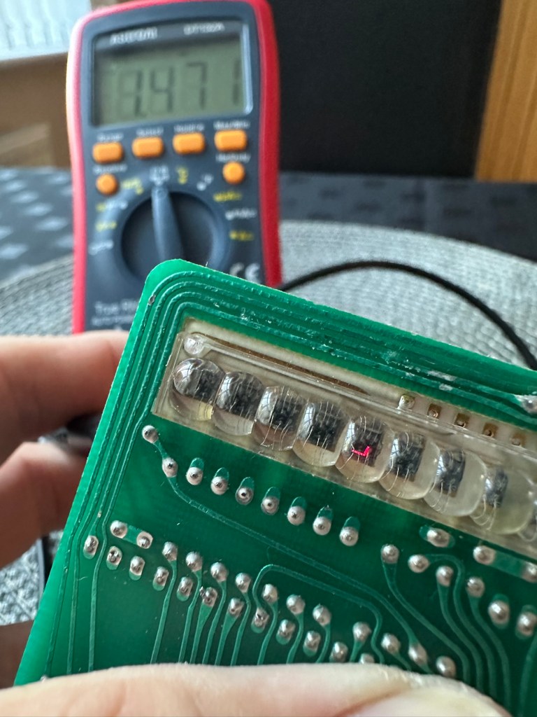
The picture shows just one part of the display range on this particular digit, I can assure you all other sections of the display are also working.

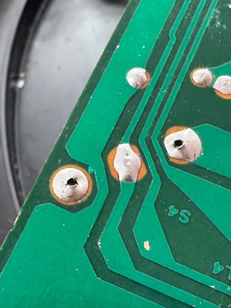
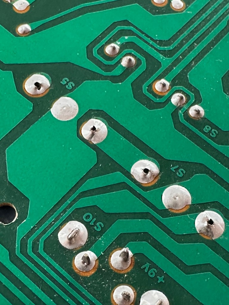
Regarding the case with the buttons not working. I have checked this out for continuity and both digits go through the same portion of the main IC and there doesn’t appear to be any broken traces. It’s a strange one but I have also found some really poor solder joints that are either cold joints or just poorly soldered from the start, there are a couple of resistors that need re soldering. It may be nothing at all, but it needs attention, a full reflow wouldn’t go amiss or take too much time.

Faulty resistor joint

I’ve reflowed the entire board due to there being a few cold solder joints.

Full reflow completed

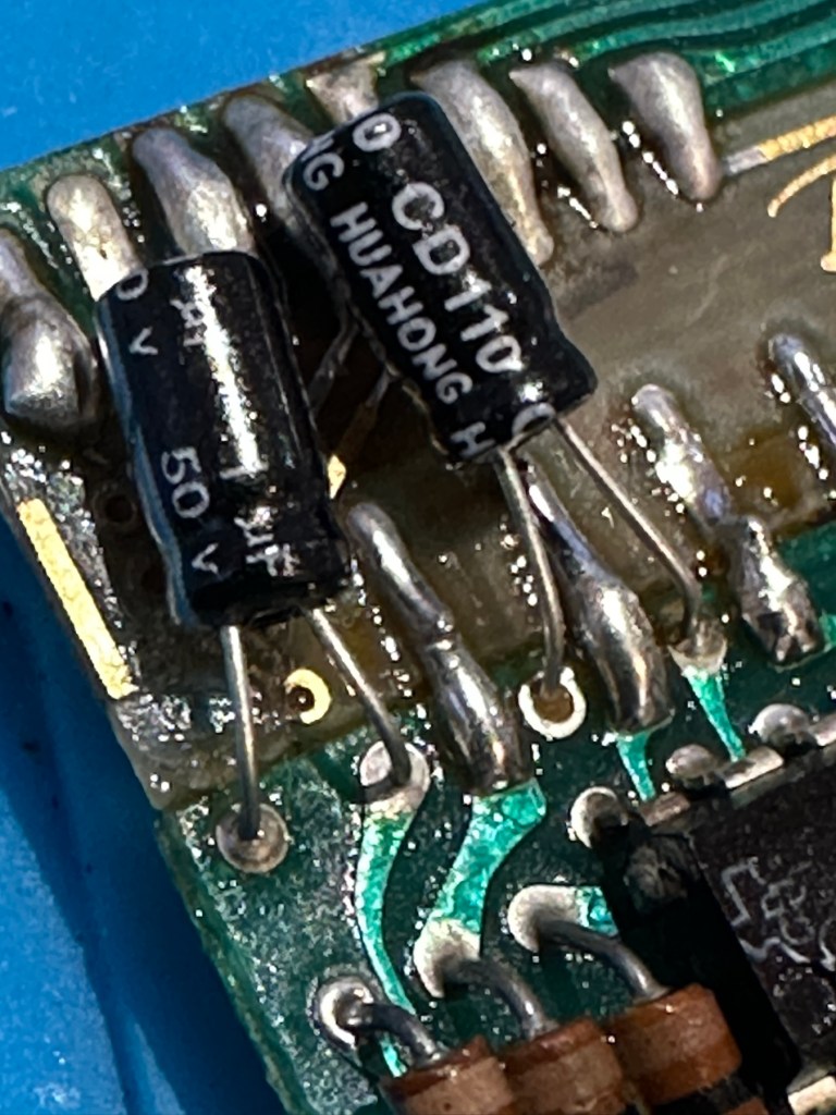
On top of this I have taken off two old capacitors and tested them out of circuit, and both were out of their operable range of +/- 10%. As a result of this I have replaced the offending components with comparable new ones.

Even with all these extra tasks being undertaken there is absolutely no change in the way it operates. Nothing has gotten worse, the faults that were originally there still remain. I have done some research on line and carried out some further tests and checked expected voltages, most are within range except one that appears to be less than its expected value. After testing everything on this board, every component I can only surmise that one of the three chips has failed, I suspect very much that this, the main chip, a CZL550 integrated circuit. Otherwise known as “Calculator on a chip” is the one that is at fault.

A CZL550 chip

To be quite honest these chips are fairly rare and command a price far in excess of what I paid for the original unit, and I don’t really want to do that. I think I’ll wait around to see if I can secure another faulty unit to complete this repair, so in the meantime, and until I can secure such a unit I will put this repair on hold.

Result:

Well, it’s not what I wanted but sometimes you just can’t win with some of these old projects. In no way am I walking away from it, it’s just that the parts are so difficult to get hold of that you really do have to just wait until a sufficiently faulty one comes up for sale. And that could be days, it could be weeks or months. So for now i admit defeat, but it will not be going to trash. It will remain in my ever expanding “To do” box, for me to pick up on at a later date. And when I am in a position to move this project on, I’ll pick it up in a continuation of this post.

Many thanks for passing by. It’s always appreciated.

MB – Simon

Remember this? Everyone had one around 1978 apart from me that is. Well, now I’ve got one, only 47 yrs late and it doesn’t work. But hey that’s what this site is all about, and that’s how I roll. Always late to the party, and even then you’ll probably find me in the kitchen 🥳

What the listing said:

Cosmetically in very good condition but does not work. Please see attached pictures to judge condition for yourself.

EBay

The guy was after £17:00GBP and that included postage, but I put in a cheeky bid and managed to get it with postage for £9:80GBP. Anything under a tenner is good in my eyes.

Here’s some history:

Simon is an electronic game of short-term memory skill invented by Ralph H. Baer and Howard J. Morrison, working for toy design firm Marvin Glass and Associates, with software programming by Lenny Cope. The device creates a series of tones and lights and requires a user to repeat the sequence. If the user succeeds, the series becomes progressively longer and more complex. Once the user fails or the time limit runs out, the game is over. The original version was manufactured and distributed by Milton Bradley and later by Hasbro after it took over Milton Bradley. Much of the assembly language code was written by Charles Kapps, who taught computer science at Temple University and also wrote one of the first books on the theory of computer programming. Simon was launched in 1978 at Studio 54 in New York City and was an immediate success, becoming a pop culture symbol of the 1970s and 1980s.

Wikipedia

From what i can see in the pictures the item seems good, cosmetically. I may be able to see just a little contamination around the battery contacts but I can’t be sure. It worries me when i see a picture that shows a screwdriver alongside the item you are buying, it just screams at me that the seller has been in side and is not being truly honest about its issues. Let’s just wait until it arrives to do a full assessment. I’m genuinely excited about getting this working, as my age veers ever closer to the higher numbers. I need something to stimulate my mind, what’s left of it. 😂

Assessment:

The unit has arrived and on first impressions looks clean and tidy cosmetically. The pads are not very responsive and the battery contacts are seriously corroded. The unit is a power hungry beast, taking two ”D” cell 1.5v batteries and one PP9 9v battery. The unit does not work with its batteries in place, and i’m not surprised really, and to round it all off two screws are missing from the case, and one screw mount is broken. All four plastic springs that sit under the coloured pads are broken, and just to clarify someone has already been in here and it doesn’t bode well. My previous concerns of a screwdriver being in the original photos have been confirmed. It’s been tampered with.

The board is a typical of many circuit boards from this era that were produced for MB. I had a similar circuit board on this item here: MB – Computer Battleship

In the picture above you will see two arrowed points. These points are the power contacts that make contact with the two seriously corroded battery contacts you can also see above. No wonder there is no power getting to the board. I suspect this might be the cause of our electrical problem.

Repair:

First thing to do is to get those battery contacts cleaned, as well as having a good clean of the main board. This has now been done. I’ve repaired the broken screw post by simply using a rubber washer that has been sufficient for this repair.

Contacts before and after

A friend of mine has kindly offered to print me off four of the “Double Y” springs to replace the ones that are already in place and broken. He owes me a favour or three and needs some subject matter to run through his new 3D printer so I’m very pleased to help him, as pending the outcome I may well buy one myself, as I have been threatening to do so for a while now. This should sort out the issue of the unresponsive pads, first found in the assessment of the item. He’s panicking that they might not be smooth and beautiful, I’ve told him not to worry as they are hidden inside anyway.

What I currently have on the left, what I’m expecting on the right

He’s just supplied me with five double “Y” pieces just in case one is damaged in some way. Let’s get these put in place to see the difference these make.

With the new springs in place the pads are working as they were originally designed to, now with some springiness in their operation. The battery contacts have now also been put back in place.

Cleaned contacts back in place

When assembled, the buttons are a little erratic and not always responsive so I decide to look into this further. A quick Look at the board shows that the solder contacts on the board for all of the button connections are worn, the solder has failed so I decide to reflow all these solder joints to improve the contacts. This appears to have worked as the unit when reassembled, now has uninterrupted operation. This is an age related issue. A simple fix.

Result:

Another 47 year old saved from the scrap heap, it’s been an interesting and sometimes confusing repair and I thank my friend who stepped in to save the day by utilising his 3D printer to make some parts. Without his assistance this repair would not have been achievable.

It’s just another old piece of retro history to add to my ever growing collection and much to my wife’s dismay. Bless her.

Now working

Thanks for passing by, as always it’s very much appreciated.

It’s true…believe me

What is the most unbelievable-yet-true excuse you have ever had for being late?

It’s not an excuse used by me but keep reading as I was party to probably the strangest excuse ever heard.

I used to work at Kodak in Harrow, nth London. It was a massive production site producing photographic film and paper. I was a team leader on a machine called track four, that produced graphics arts film for industry, a sprawling machine that went through three buildings, went underground and then up through seven stories before being collected about 1500 metres away from where the process started. It was a massive piece of equipment.

Part of my responsibilities was looking after a shift team of around eight men, ensuring the swift and efficient running and maintenance of this machine and to achieve excellent up time results.

Occasionally people were late, it just happens. But one shift this guy was about 2 hrs late and he was called into the office to discuss his lateness. He was a great guy but always had some spectacular excuse to offer.

This evening apparently, his daughter’s hamster had escaped its cage and disappeared under a floorboard. Its escape meant some floorboards had to be lifted to recover the escapee, and whilst doing so the rescuer (namely the chap sitting in the office beside me) had to wedge himself between the floorboards and a central heating radiator. He then got stuck. The central heating then turned on and he then apparently burned his arse.

His wife rescued him before he roasted like a piece of prime silverside and then he was able to make his way to work. The hamster had succeeded in its escape bid and is now living in Brazil for all that I know.

So whilst explaining his misdemeanour to me, he seemed determined to show me evidence that I politely declined, however he was determined and in front of me in my office he dropped his trousers exposing his now rosey red cheek. And as if by magic at that moment another member of staff knocked and entered the office to see me gazing at the full moon that had been exposed to me as evidence. He left very quickly.

But I knew that this incident would now be around the team quicker than a greyhound around a race track.

Later that evening the name “Doctor Dave” was being used around the team. And it stuck for the next four years until the company closed.

Just a moment in time that makes me smile.

Have a lovely day.

Psion datapak formatter

What the listing stated:

old computer bit , powers up ( red light shines on ) but otherwise untested  , please note my other similar computer items      

EBay

My previous post Formatting the Psion II Datapack explains my thinking and reasoning behind making this purchase.

Most EPROMS made around this time in the 1980s had memory that could be formatted by using a method of exposing them to high levels of Ultraviolet light for between 10-30 minutes. The Psion Datapaks required about 30 minutes of “exposure” in one of these units to format the drive.

By high levels of light, i mean UV light around the wavelength at or close to 253.7nm. A UV light you may have in your home or in the form of a torch operates at somewhere around 395nm, a considerably safer wavelength of operation than what is needed to format these EPROMS.

The UV light spectrum. As you can see the wavelength we need to format the Datapak at 253nm falls into the dangerous UVC Shortwave spectrum. The standard house hold UV light or torch falls into the much safer UVA Longwave category at around 395nm. Picture courtesy of The Hepacart blog.

This unit was purchased after I had spoken to the seller, a nice chap that specialised in old diy tools and computer peripherals, but wasn’t quite sure what this unit did or how it operated. He had stated that the red light was working, but nothing else. My concern here was that the UV light inside was broken, and these tubes i believe are known as low pressure mercury discharge tubes, and finding them in this size is pretty difficult to say the least. The UV tube in this unit could potentially be 40yrs old as this is a Mk1 unit circa 1984. I just don’t know if its tube has ever been replaced at all in its lifetime. Have a read of this post by Dave Curran who had similar issues sourcing a light supply for one of these units, it resulted in him having to make a hybrid concoction combining one of these units and a cheap Chinese import – Eprom eraser/upgrade

I asked the seller, John, if the Ultraviolet light inside was operational and I have supplied a screen shot of his reply:

The reply to my question

When I received John’s reply I jumped in with an offer and this was accepted. He had been so helpful. I’m now awaiting the unit, but I’m now a lot more confident that the unit, and most importantly the UV light is currently operational. However it’s probably going to be subjected to some pretty rough conditions on its delivery journey, so I’ll keep my fingers crossed for now.

This formatter is a series one version that came out around the same time as Psions Mk1 organiser first appeared on the scene, circa 1984. It was used right through to when the MK2 organisers were released sometime between the years 1986/89.

This unit will be cleaned, opened up, checked for electrical and mechanical stability, its safety features will be confirmed and it will then be reassembled and PAT tested prior to use. Once this is done i will attempt my first format of a Psion Datapak whilst the unit is in my possession. However we have a little way to go just yet, before we can consider carrying out that task.
The seller was very prompt at getting the unit out to me as it has arrived less than 24hrs later.

The general condition on first inspection is that it looks good, but it’s very dirty and has a slight musky dampness to it. I have given the plug and the cable and case a good clean with a bit of degreaser and this has cleaned well. I’ve done this just so getting inside is a slightly more pleasant experience without my hands getting covered in gunk. The unit looks a lot bigger in the pictures. It only measures 19cm L, 10cm W and 7cm H, so in theory it’s relatively small.

Before I do go inside I have first checked the plug, it currently is carrying a 13amp fuse that is way to large for this unit. It only requires a 3amp fuse so I have replaced this. I haven’t used the Pat tester yet I’m just using the multimeter, and I’m a bit concerned as there is no continuity between the earth pin and the unit case. Time to get inside.

Inside looks tidy but I then become aware of a problem immediately. The earth wire from the mains cable is just sitting there in mid air connected to nothing. No wonder there was no continuity. I have now connected this back in place where it should be and I now get a good earth continuity throughput the casing. All other connections checked and tightened accordingly. This proves that the Pat test would have failed miserably. This was a potentially dangerous situation, that’s why it’s best to carry out these checks on any old powered units you get from a third party. Trust no one.

Next I need to check that the safety switch that turns off the UV light when the drawer is opened is operating. Again I use the multimeter to probe the switch and this seems to be ok. A good listen to the action confirms that it is clicking in and out. A quick clean inside and then the internal checks are complete.

The safety switch clicking in and out

There is no real way to test for actual operation until the safety case is back in place, that’s the safest way. Case on and another quick clean and the unit is looking good .

At this point I’ve carried out the Pat test before plugging it into the mains and the results have come back good and it’s a pass, the earth is good. I’m now confident about plugging the unit into the mains.

Everything seems fine I now just need to place a Datapak inside to see if the format process works. Also it’s a good time to check if the 30 minute timer is working. No time like the present, so I’ve found a suitable candidate and what better way to do the 30 minute countdown than with a Psion organiser I just happen to have hanging around. Here goes 🤞

The unit has been on about 15 minutes and all seems fine, the unit is not overheating and there is nothing occurring that shouldn’t be occurring. Fingers still tightly crossed. 🤞 The Psion timer duly sounded at the 30 minute mark, the unit turned itself off about 2 minutes later.

It continued about another 2 minutes after the timer finished

So 32 minutes seems to be the actual time under the lamp. Not too bad considering its age. The unit was only slightly warm to the touch after this time. I’ve left the Datapak to allow it to get to room temperature before testing it .

Success the system is sizing

Here we go, and it’s fantastic news as the format has worked. When plugged in it has informed me it is going through the sizing process that occurs on these organisers when you put in a newly formatted pack.

And when you go to check the info you can see the previously stored old data has now been deleted.

I now have a very useful, safe and working item of equipment. A very slight mustiness remains but that is only to be expected with an item that is 40 years old that you have had no input into how it is stored. I’ll probably store this in a sealable bag with some silica gel sachets to try and draw that mustiness out. I’m really pleased with this project and now have a very handy piece of kit to boot.

As I said earlier, make sure you always check thoroughly any items electrical such as this, coming from a third party. It’s your life, preserve it, safety first and trust no one. It’s a good mantra in this aspect or restoration.

Another item saved from landfill 👍

Thanks for taking the time to follow this project.

Formatting the Psion II Datapack

The Psion II range was well ahead of its time when it came to saving data on its machines, however there was an element of strangeness in its design and usability.

You have to realise we are talking early eighties technology and to be totally honest it was the infancy of computing, or hand held computing to be precise. There are three drives on this range of handhelds, they are A:, B: and C:

A: is the internal memory of the unit and it is RAM memory and ranges from 8KB in the CM model, to 16KB in the XP model right through to 32 or 64KB in the LZ/LZ64 models.

Datapaks on a Psion II unit

B: and C: drives are found on the rear of the unit. Into these slots you can place memory modules that are the equivalent of disk drives you’d find on a computer, however they are pretty much early solid state in design as they have no moving parts. These modules can come in sizes between 8-128Kb in size. B: is always the top slot closer to the screen, C: is the bottom slot closer to the battery compartment.

Types of memory

Rampaks are as it says on the label – Ram based plug in memory modules. When you store something in the units internal memory or on a Rampak, and then you later erase it, it really is erased in its entirety and space on the unit or Rampak is freed up, ready to be used again. Rampaks will have their own small “Coin” type battery as part of the module, this allows the unit to allow the constant input and deletion cycles. They use very little power and are probably the best medium for writing programs.

Datapaks are a different beast. They are known as EPROM (Erasable Programmable read only memory) Erasing a record is comparable to crossing out a piece of work written on paper, it has now been deleted but will always remain on the paper, just crossed out. It’s exactly the same on the Datapak. Hence in time the memory space will dwindle due to the deleted files that remain still occupying dead space. The benefit of the Datapak is that they are more secure and are not affected at all when battery power runs low.

With a Datapak there will come a time when the available memory space remaining is insufficient for what you are trying to achieve. At this point you need to format the drive and this is a particular problem if you don’t have the access to equipment to carry out this task. Here’s why…. They need exposure to Ultraviolet light to erase the memory.

Mk2 version of a Datapak formatter

You need one of these, a Datapak, Ultraviolet formatter. Quite a rare beast to be honest, there’s not many on sale at the moment, specific to the Psion. However there are other systems available for EPROMs used in other branches of electronics. The Datapak has to have its label removed to expose the crystal glass below on the EPROM in preparation for being placed inside the formatter. In theory it is just like an oven that exposes the EPROM for around 30 Minutes, the door is closed prior to formatting to keep the light source from damaging the users vision, as the light is in the UV wavelength spectrum likely to cause some quite serious damage or long term conditions.

Here you can see a Datapak that i have taken the lid off of. On the circuit board you can see a piece of crystal glass with a silicon die below, this is the component that will need approx 30 mins of Ultraviolet exposure to format its contents.

The crystal that the UV light needs focusing on

The formatting process

Erasure of the EPROM begins to occur with wavelengths shorter than 400nm. Exposure to sunlight for one week or to Fluorescent indoor lighting for three years could cause erasure, this is why the Datapak has a label covering the crystal portion of the EPROM. The recommended procedure is to expose the EPROM to a UV light source at a wavelength at or close to 253.7nm that usually achieves the format process within 20-30 minutes, with the lamp at a distance from the glass lens of around 2.5cm.

Then how do I achieve a format of a Datapak without this equipment?

There was always the option of trying a standard UV bulb or torch. However the UV wavelength on these items for public safety is usually in the 395nm wavelength spectrum. There really is very little available to the general public that is as strong as the bulbs required in the 253nm range to complete this task, as they are a serious danger to health if you are exposed to it for any length of time. This then was not an option i was able to pursue.

I now have a few options available to me if i wish to get these Datapaks formatted.

Purchase a cheap Chinese manufactured unit with a European plug. They seem to work and do the job, however you will be lucky if you get a couple of uses from it.

Trawl EBay. As i write there are two working ones including this MK2 version listed at a reasonable asking price that have a lot of people watching them, so I expect the price to rise accordingly as it gets towards the close of the auction.

EBay spares or repair. There is one unit, a Mk1 version that has a buy now price and it seems to have been hanging about in someone’s junk box for a few years and could possibly need repair. This is a tempting option however if the UV light inside is damaged then i have to look for a suitable replacement, and to be honest there are not a lot of compatible low pressure mercury discharge tubes of these sizes available now. You may have to look for suitable alternatives and I’m not sure i want all that messing around. Do i take the risk and go for one that may need repair? A guy called Dave Curran has combined this drive with one of the Chinese low cost options to create this hybrid eraser: Eprom eraser/upgrade

Get someone else to do it. There is this option and a service is available on line that allows you to send your Datapaks off for someone else to format for you. But do you want to entrust data to a third party? For me it’s not really a problem as none of my units have any of my data on them, but it is something to take into consideration. Whilst I’m searching for a suitable unit this may be a route i consider.

So these are my options. I’ve an idea what I’m going to explore, so im just going to take a little time to look into it all.

My decision

EBay spares and repair – seeing that this is a site where i like to purchase and repair items, i have gone for this option and purchased a used and typically untested Mk1 Psion Datapak formatter from EBay. I have had some good dialogue with the seller and i am confident that this unit can be made good with only a small amount of intervention. The UV tube inside is potentially 40yrs old now, i’ve secured it at a very reasonable price as i got in there and was able to complete the deal relatively quickly.

My plan is to get this unit opened, check its mechanical and electrical stability, get it cleaned, reassembled and then Pat tested. Only then can i look at attempting a full format on it for the first time. And for that i will put together another post incorporating the repair of the unit and the formatting of the Datapak.

Here is my restoration of this unit: Psion datapak formatter

Thanks for passing by.