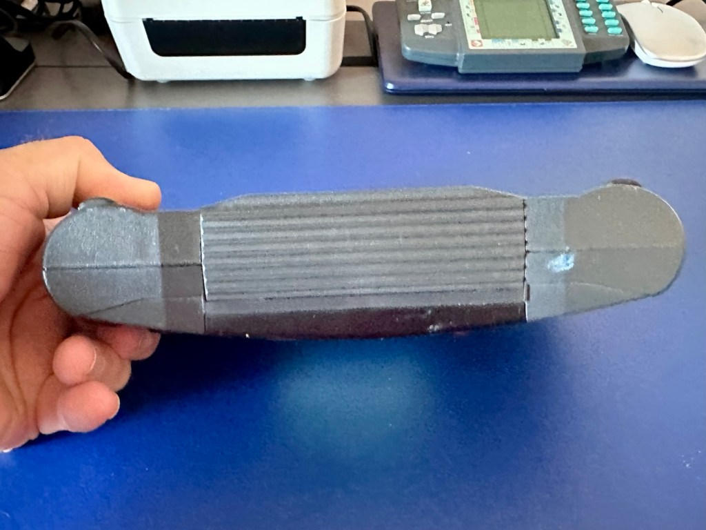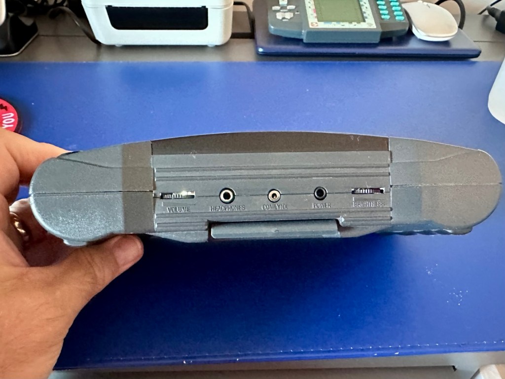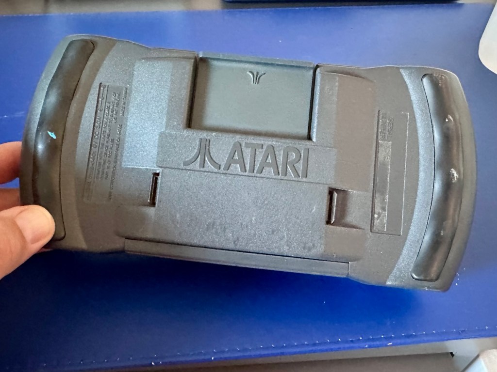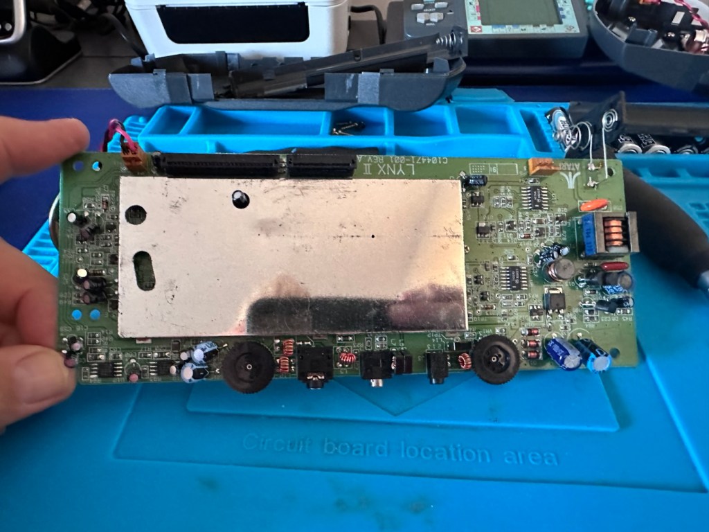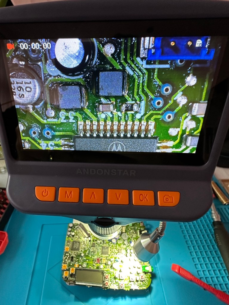

Atari Lynx 2 handheld games console

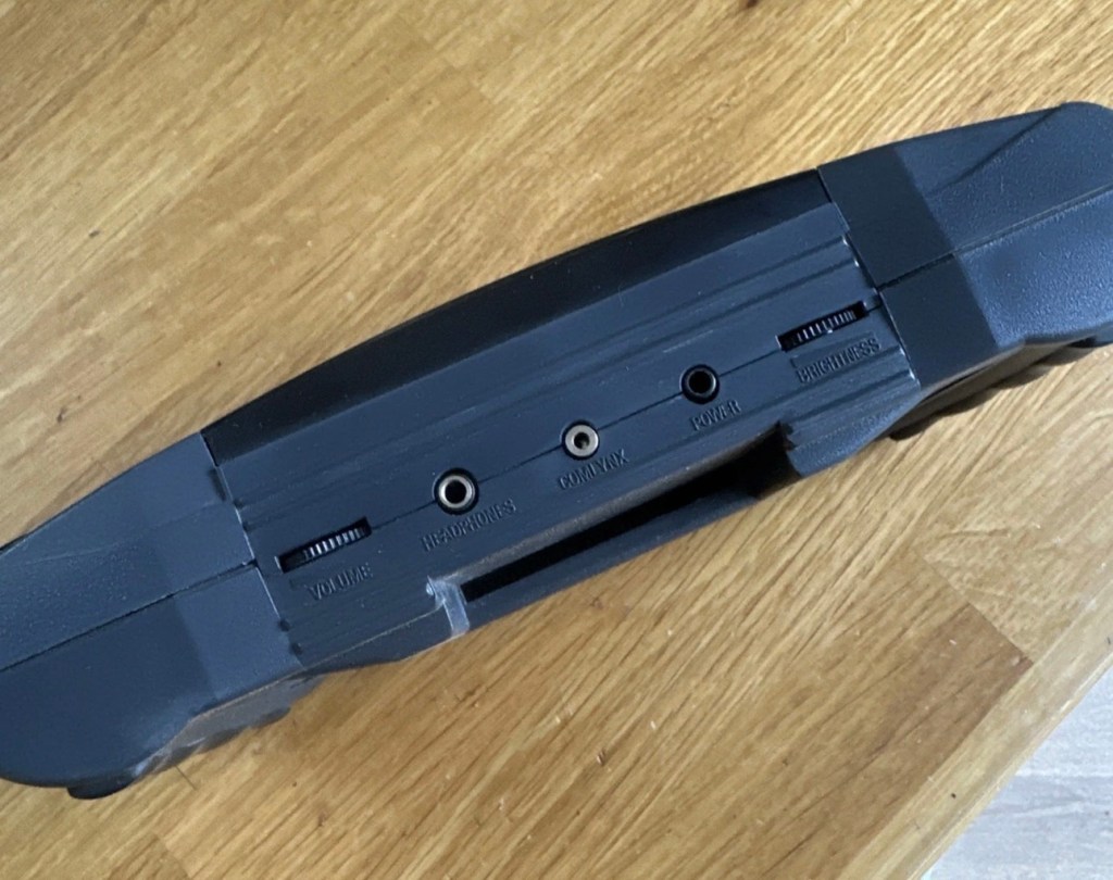
Meet Mikey, and Suzy! Well it’s actually an Atari Lynx II from 1991. Mikey and Suzy were the names given to components within the console. Anyway it doesn’t work, so let’s try to breathe some life into it.

What the listing stated:

The product is an Atari Lynx 2 handheld console, originating from Japan. It is a spare or repair item, as it is not in working condition. The package does not include a charger. This vintage gaming device, released by Atari, offers portability and gaming capabilities. Ideal for collectors or enthusiasts looking to fix or restore a piece of gaming history.

EBay
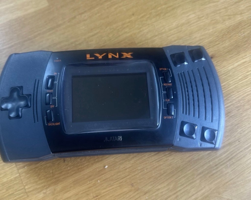
It’s a faulty item, one of many I have been chasing over the last few months, however their resale prices even when faulty, can command some quite hefty prices. I’ve managed to purchase this one at £65:00GBP and that is a price I am content with, as some of the recent ones I have seen went for a higher price even with parts missing or body damage. Cosmetically this one appears to be in a good condition with everything intact. However, the actual fault has not been declared, just that it is faulty and not working. I will have to do a little fault finding to pinpoint the issue, though I suspect initially that a full capacitor change will be the order of the day.

I want this to be part of my personal collection, alongside the Lynx 1 that I also have.

Here’s a little bit of information regarding this unit:

The Atari Lynx II, released in 1991, is the sleeker, redesigned version of Atari’s pioneering 16-bit handheld color console. It addressed original flaws by offering improved battery life, a backlit LCD, and stereo sound, while retaining impressive hardware features like hardware sprite scaling and a unique “lefty” flip mode. 

Key Features and Design

The Lynx II packed advanced technology for its time, including several highly unique design choices:

The Display: It features a vibrant 3.5-inch color LCD. Unlike the original, the Lynx II included an option to toggle the backlight off to save battery. 

Left-Handed Mode: Because of its symmetrical control layout, the entire system can be flipped 180 degrees. The internal software features a “flip” button to invert the screen, converting it into a truly left-handed console. 

Vertical Gameplay: Some games, such as Qix, are designed to be played holding the system vertically like a book, taking advantage of its unique design architecture. 

Comlink Play: It supports up to eight players for local multiplayer over “ComLynx” cables. 

Hardware & Power Specs

Processor: 16-bit custom CMOS chip (nicknamed “Mikey”) running at 16 MHz.

Graphics: Custom graphics chip (nicknamed “Suzy”) featuring hardware sprite scaling, zooming, and distortion.

Battery Life: Runs on 6 AA batteries, which deliver about 4-5 hours of gameplay with the backlight on. Due to this high power consumption, an AC adapter was a common necessity. 

Courtesy t’internet

So, without any further suppositions as to what’s wrong with it, let’s just await its arrival to carry out a full assessment.

Assessment:

I believe that to do a proper test on these units you have to have a game cartridge installed, this is my first issue, I don’t have any cartridges so I have had to purchase the cheapest one I could find for testing purposes. I’ve managed to pick one up for £11:00GBP and to be honest that isn’t too bad. It may well be the worst game they ever produced, who knows? But it will be fine for testing purposes.
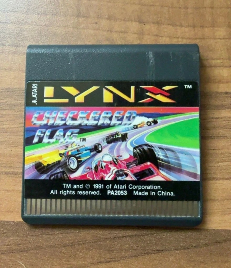
Checkered flag for the Atari Lynx

Well, we still wait. Two weeks down the line and only the game cartridge has arrived. Not much I can say about that apart from it looks ok.
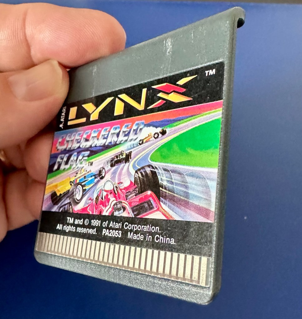
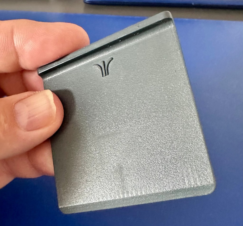
If the game doesn’t function there is not a great deal I can do here. As you can see it’s just a wafer thin plastic plug with no user access available. About the only thing you can do is clean the contacts.

We just need the console to arrive now……

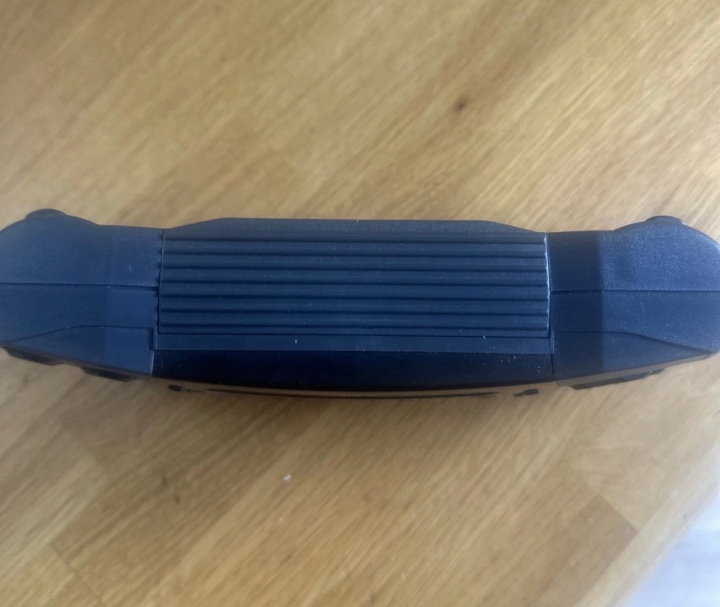
And it’s arrived and to be quite honest it is in a good condition cosmetically, and for an item that’s now 35 years old it has been well looked after. No need to put any batteries in as there are already a fresh set in there, I have checked their voltages and they are fine. 6 x AA batteries turning out around 9 volts, the units requirement.

As I have previously stated, without a game cartridge installed the unit does not turn on. When a game is installed and the unit is turned on, I get an audible short “click” and the back light of the screen comes on, I get nothing else and am unable to get any sound or adjustment on either the volume or screen contrast dials.
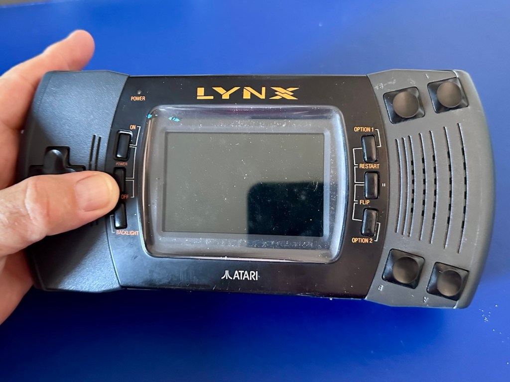
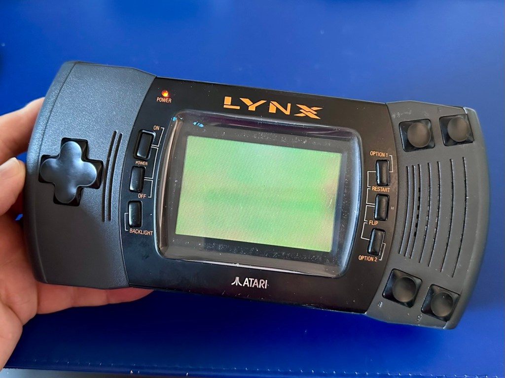
It’s looking very much like either a screen issue, or an issue related to the failed capacitors on the main board. There is one particular capacitor “C41” that controls the main power board that is notorious for failing. I will check this initially to see how it is fairing, if it is ok I will make my way through the board checking other components as well as looking for other points of known failure such as weak solder joints.

Repair:

Firstly, let’s get into the unit, and this requires the removal of five screws in total.
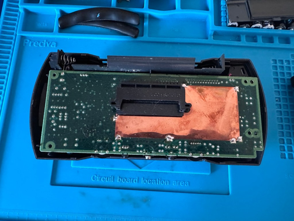
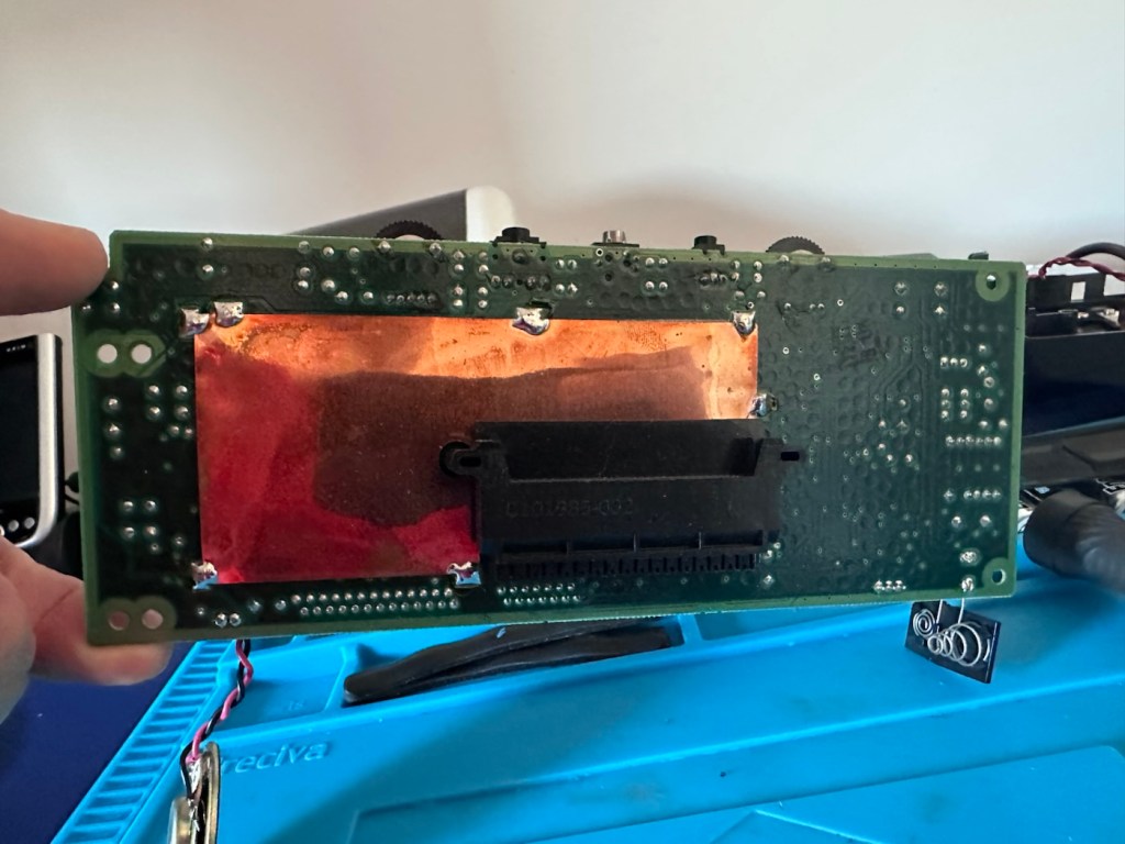
The back should then lift off. Carefully remove the two screen ribbon cables, the power jack and the speaker jack and the whole of the main should just lift out.

A word of warning here. The power side of the board has a number of points that if touched will give you a nasty jolt of many hundreds of volts, a very quick and potent shock and you will certainly know what’s happened. Be very careful handling anything in this area, especially around the capacitors, and always make sure you bleed the power once the power source has been removed. If you are working live in this area, please be very careful. It’s amazing that just 9 volts of injected power can create such high voltages. You have been warned!

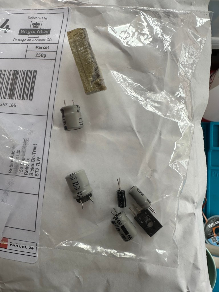
I’m going to order a full replacement capacitor kit, for an item of this age it’s probably a wise investment if you want the unit to be around for a good few years yet, even if the caps are not at issue they would probably need doing in the end anyway. The capacitor kit in its entirety (number of caps*) costs £9:80GBP and that’s a really reasonable price to pay to ensure the units usage can continue for many years to come.

The capacitor kit has arrived and there are 24 included. I think there are only 20 to replace (I could be wrong) so I may have a few left over.

The capacitor kit

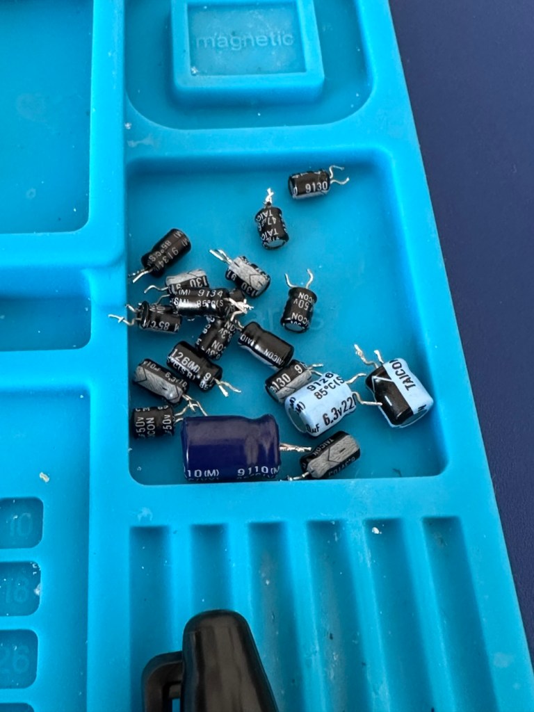
I’ve started by removing the most prominent known capacitor that falls and that is C41. It’s a 10v 470uF value and has a tolerance of +\- 20%. So in Theory this capacitor has a value that can fluctuate between 376 and 564 micro farad, and the one on this board is registering 514uF. In theory it is still working, however it’s gradually creeping closer to to the limits of its tolerance.
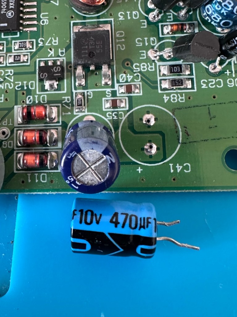
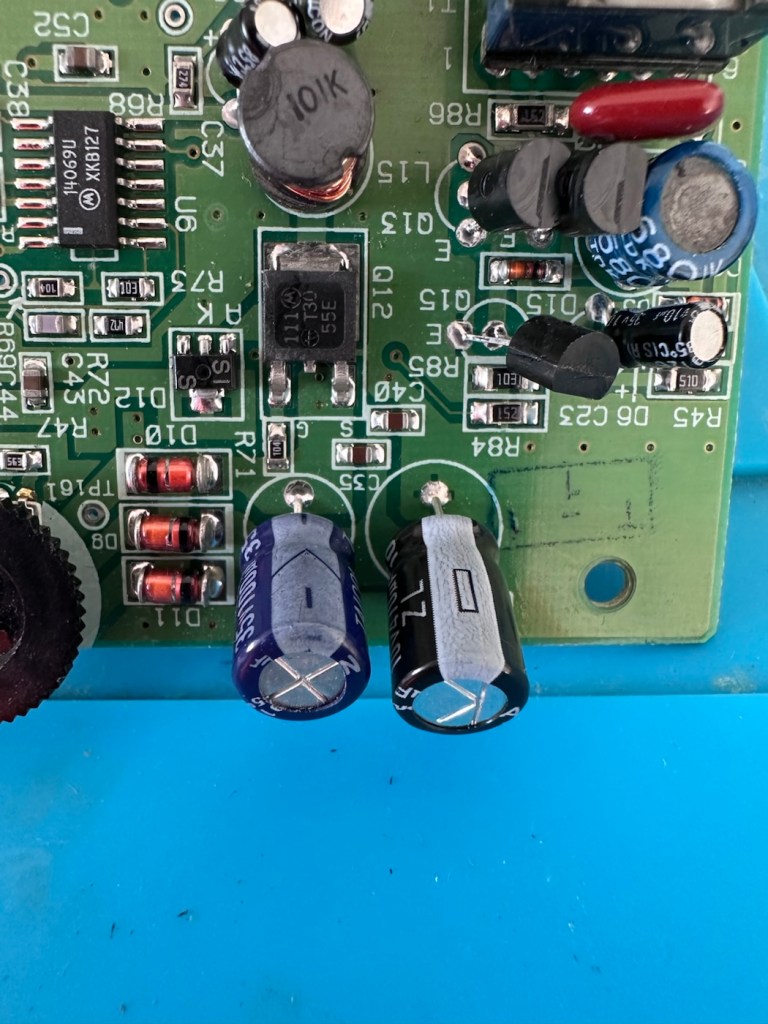
And to be honest, that was pretty much the same result with the other 19 I replaced. All were within their tolerance but at the higher end. The problem here is not capacitor related, however it’s always a wise move to replace them, before they finally go bad and cause other issues.
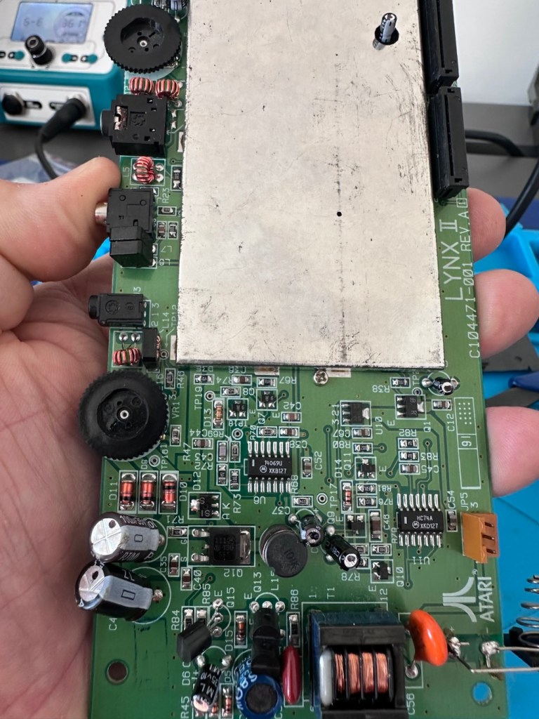
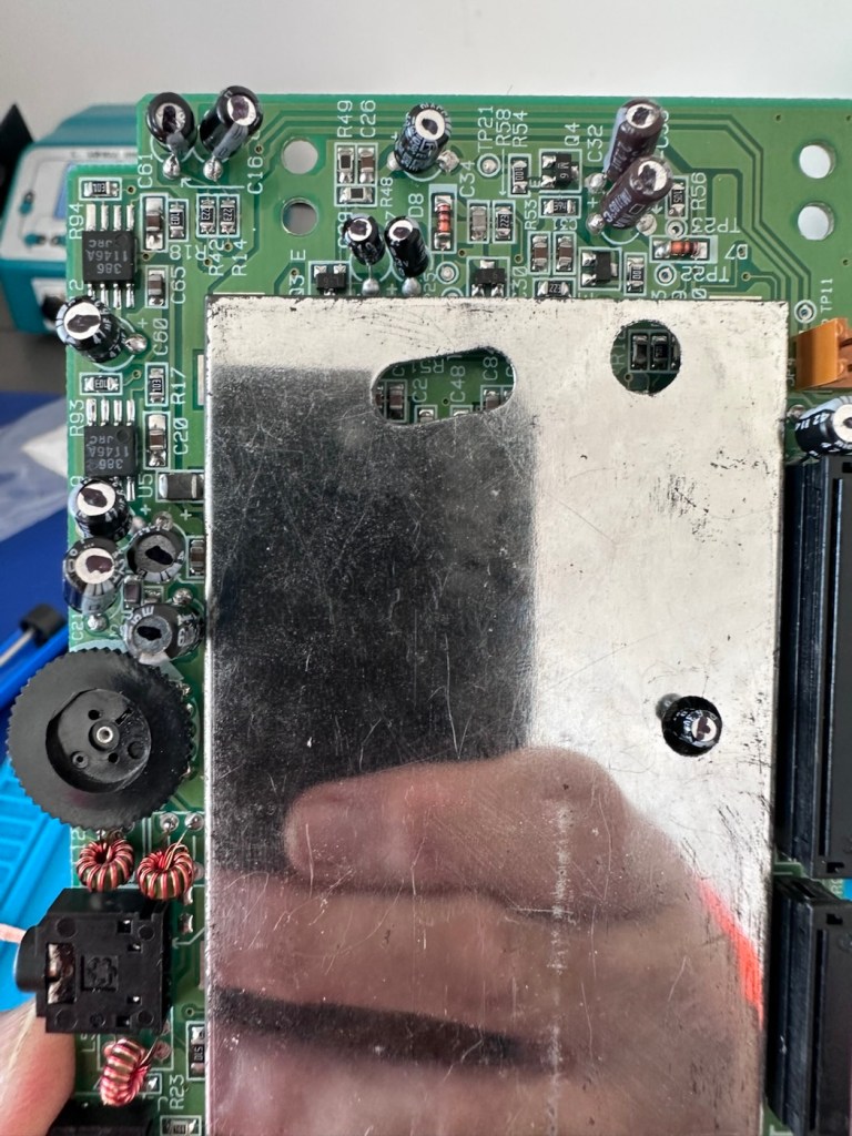
The recap has been successful, however I know it’s not going to make a difference, and putting it back on power confirms this. There is no difference to what I was experiencing when I first tested the unit.

No change

Annoying though this is, it is a job that needed doing and I’m now going to have to focus my attention elsewhere. I’ve checked the polarity of all the capacitors and I’m confident they are installed correctly and in the right positions. There are a few tests and checks to yet carry out, I’ll just have to do a bit of investigating to take this repair further.

These boards and their components such as the main chips and ram were developed to work with a power of 5 volts. However the problem here is that the supply via batteries or via an external power supply is 9 volts. Here lies the issue. On these units the power suppression part of the circuit, those components that filter and lower the voltage from 9v to 5v were known to fail, and when they did they failed quite spectacularly. With no protection built in to stop a surge of power, if some did fail, the full 9v would be supplied to most sensitive components rendering them beyond useless, and non repairable unless you have another donor board. Worst case scenario here is that the main CPUs of which there are two, could both be dead. In which case I may have purchased an expensive paperweight! But hey, let’s not go there just yet as there are a number of things we can do to check.

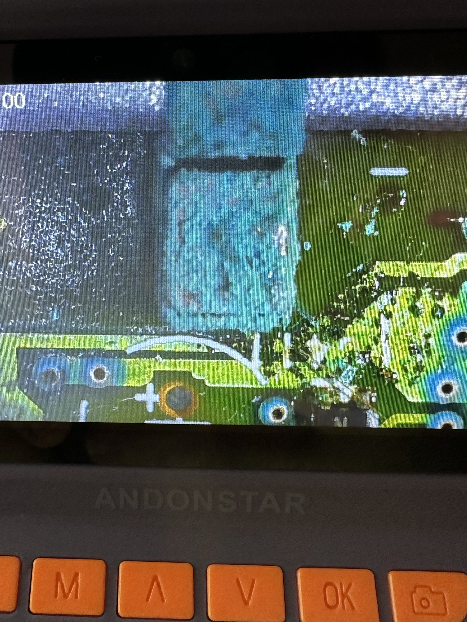
Next thing I have been doing is testing voltages around the board, and they are a little erratic to say the least. It is pointing towards the power board having its usual known issues. I’ve bypassed the power circuit to run a pure 5v through capacitor C14, same outcome here, this disappointed me as I was hopeful the game would kick in, it’s looking more like one of the chips have blown, the further I investigate.

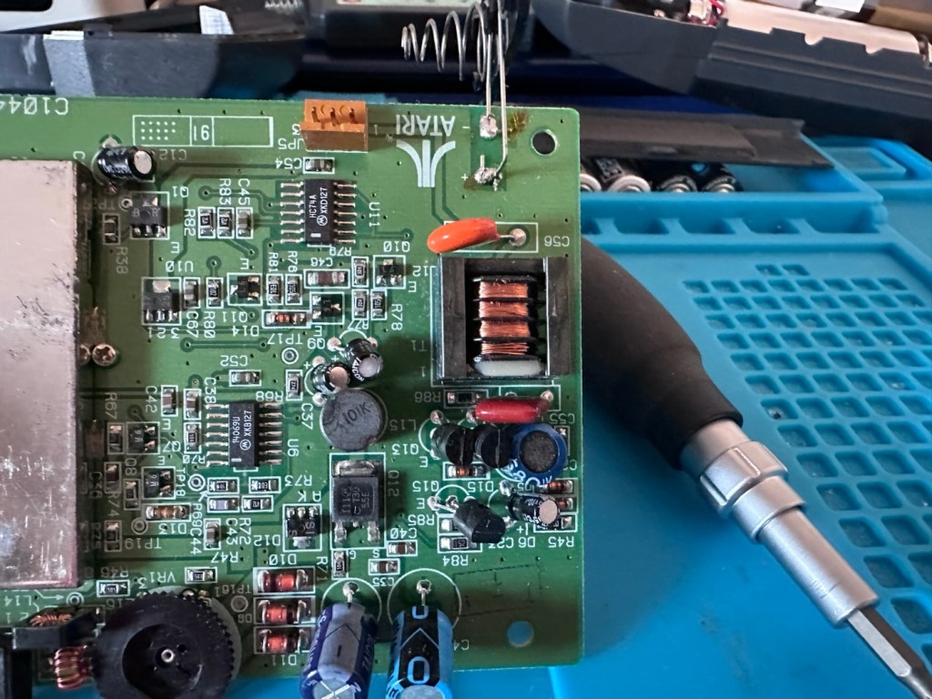
I have done a bit more testing around the power components and I have definitely found an issue with a diode D13, it’s letting power through in both directions and this is not right. I suspect there are more affected components in this area so I’m just going to go ahead and purchase a complete pack of replacement components for those known and prone to fail, on the power circuit. This will cost me £6:79GBP, another cost to add to this project.
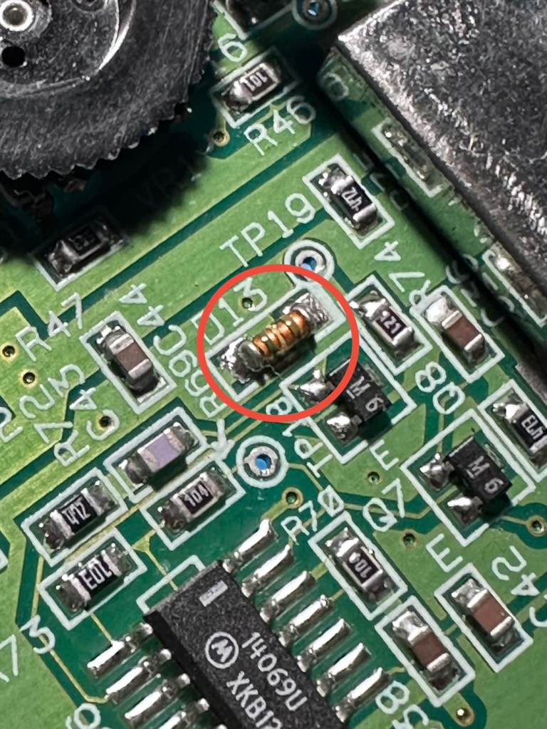
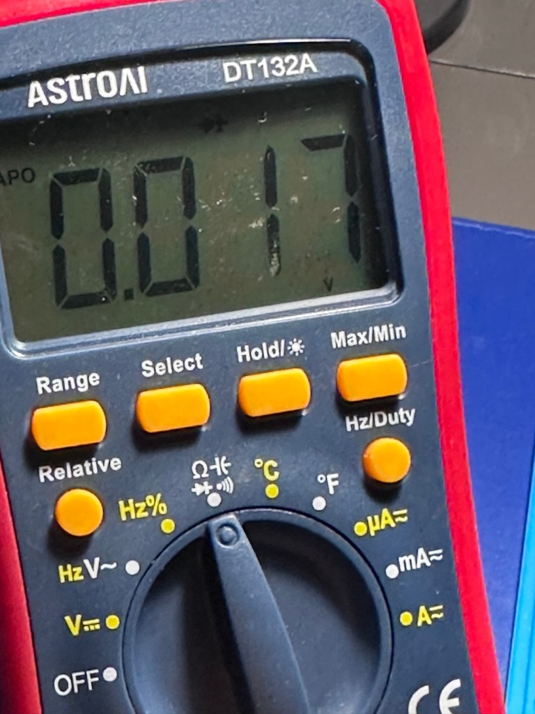
I’m not hopeful though. Current testing results are all pointing to something more terminal. We will persevere for the short term though.

The parts required for the power board refresh have arrived.
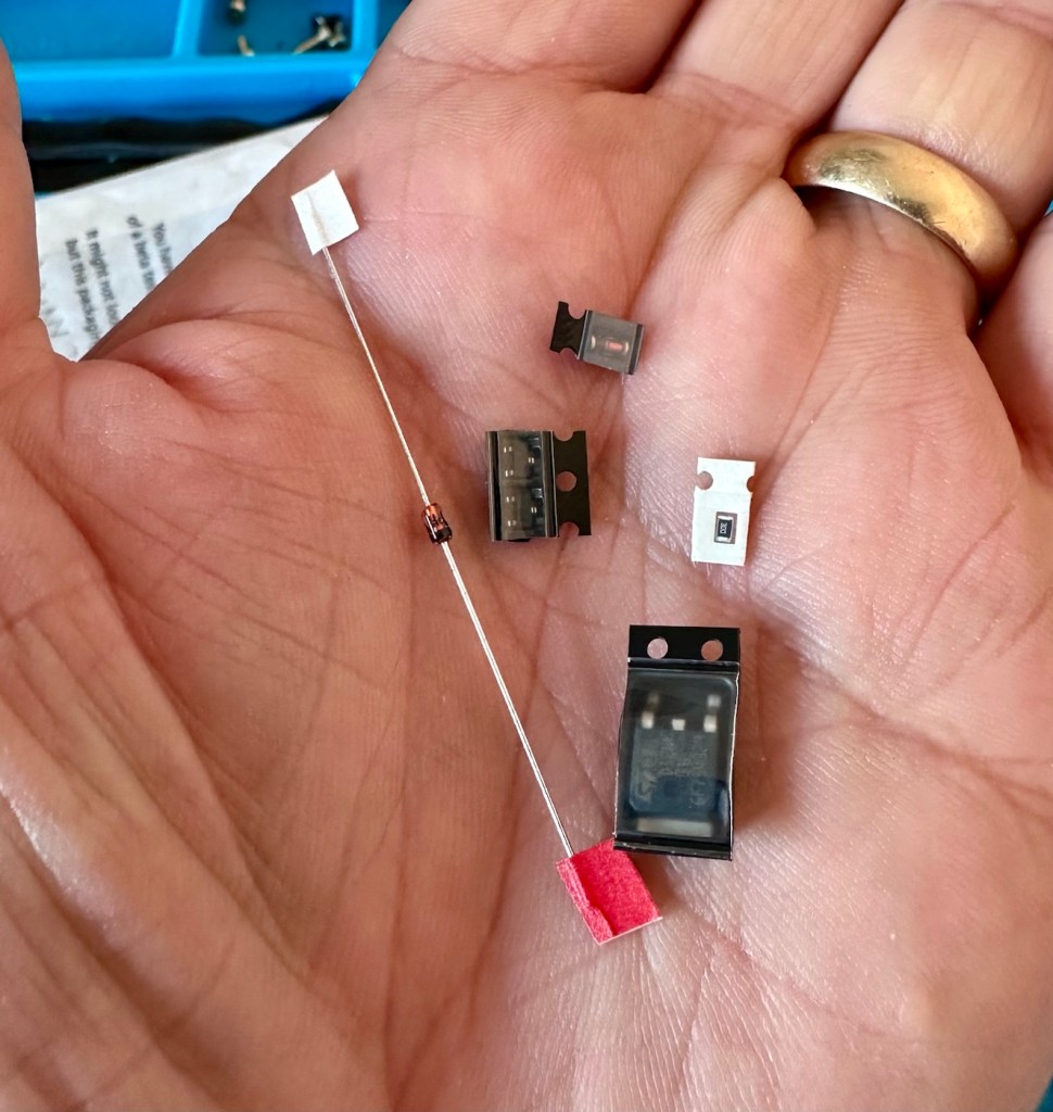
6 of the tiniest replacement parts

And they are minute in size. Installing these components is going to require a lot of patience and concentration.

The company that sell this power board refresh kit in the UK is ZedLabz.com and this is what their accompanying paperwork states:

Within this kit you will find a replacement Mosfet, two transistors, a resistor and two zenner diodes of different mounting types.

Part locations:

Q11 – Mosfet

Q4 & Q13 – Transistors

ZD1 – Zenner diode (two mounting types included)

R56 – Resistor 30ohm

This parts kit can be used on an Atari Lynx 1 or 2 handheld. One surface mount SMD and one axial through hole zenner diode are included, making it suited to both Atari Lynx 1 & 2, you can choose which type of diode you want to fit.

The kit also includes a resistor which can help with some models to push up the voltage enough to get it stable.

The parts we supply in this kit are from Major distrbutors only ensuring they are genuine.

Console dissasembly and internal soldering required.

ZedLabz.com

No kidding there! It should really say some soldering of components slightly smaller than a grain of rice is required. Let’s stop the whining and just get on with it.

I have replaced all of the five components that needed to be replaced, I’m really quite pleased with the job I have done considering just how tiny these components are, my soldering skills appear to have improved somewhat as a year or so ago I wouldn’t have even attempted such a job. That’s the positive.

But now the negative.

It’s Dead, very dead.

There is still no improvement despite pretty much an entire rebuild of the circuit. I have checked all voltages and they are in the right place showing the correct values. It’s been recapped, the power board has been rebuilt, all solder joints have been checked and ribbon cable connections have all been reflowed.

Result:

My conclusion that the previous owner was well aware of the issues, they probably contributed to the problem and the unit has been sold on as “spares and repair only”. I have failed to pay attention to the old Latin saying “Caveat Emptor” or buyer beware.

The situation is this. A new LCD screen can be purchased to drag the unit into the 21st century, but there is no point when we have no sound and vision being produced. The problem here is that the 9v power supply has already been able to get to the delicate parts of the circuitry where only 5v should be in attendance. I am 99.9% certain that the ram chips as well as the two logic chips “Mikey & Suzy” have long departed. And there lies the problem. The two logic chips are as rare as hens teeth and are pretty much only available when transplanted from a donor unit. The unit is basically dead, it’s just a paperweight.

I will put the unit into storage until a later date, when I have done a lot more research and who knows I may even find a suitable donor board to transplant those two logic chips.

For now the project is on hold. I don’t like writing of failures as many hours of work over many weeks has been dedicated to this project. You can’t win them all though, and some you just have to step away from a project to get a fresh aspect on it. Having this log of activity is fantastic for me though as it will now become the reference for where I go next.

It’s a learning curve, that’s for sure.

When I come back to the project I will obviously link to this post.

Thanks for passing by. It’s always very much appreciated.

Mamiya M Autofocus – 35mm point and shoot camera

What the listing stated:

Mamiya M point and shoot camera. It’s in fantastic original condition and is cosmetically excellent with original case and lens cap included. The lens appears to be bright and clear from the front. 
HOWEVER…when batteries are inserted the shutter does not fire and I suspect it is jammed somewhere. The lights come on and it goes “click” but the aperture does not open, nor does the film winding do anything. 
For spares or repairs only, I’m sure somebody with the know how could get it up and running again. 
Priced super low as I want it shifted and can’t bring myself to bin it! 
No returns please

EBay

Here’s a little bit about it:

The Mamiya M is a 35mm autofocus compact from 1982.  It has a boxy plastic shape, with a fixed Mamiya Sekor 38mm f/2.8 lens.  The lens is four elements in three groups.  Exposure is fully automatic, based on the film speed, where the ISO is selected via a dial around the lens. Film speed available is 25 – 800 ISO.  

The metering cell is located just under the lens, but within the lens ring.  This allows for the metering to take into account any 46mm filter screwed onto the lens.  That is assuming it is not a graduated filter.  Fastest shutter speed is 1/500thsecond with the slowest at 1/8th.  The camera is always on, except when fitted with a specially designed lens cap, which triggers the off state.  There is a strategically placed switch it pushes against on the right side of the lens.  Most of these caps are lost, including mine.

Photothinking.com

I don’t know what attracted me to this camera, but the fact the seller just wanted rid of it at a cheap price was a starting point. It was advertised as £4:36 GBP and £2:45 delivery, a total of £6:81GBP. I bartered a bit and got it all in for £5:44GBP so I got it a little bit cheaper, a bargain if you like.

Mamiya has a great reputation for building high quality lenses. They were only in the 35mm autofocus point and shoot sector for a short while before immersing themselves totally into the medium format camera market. This 35mm camera was only in production for about a year or so, even though quite a few were produced, we are looking at the low hundreds of thousands, not the many millions, so the camera itself was not a major mass produced and marketed unit. It is a plastic preformed body unit. Known in polite society back in the day as “A plastic fantastic”.

If a Mamiya camera had a blue ring around the lens, specifically on its other models, it denoted a higher quality lens type, it was never confirmed this was the case with these small autofocus 35mm cameras, though many believe it is still the case. Photo quality with these little units was generally of a very high quality.

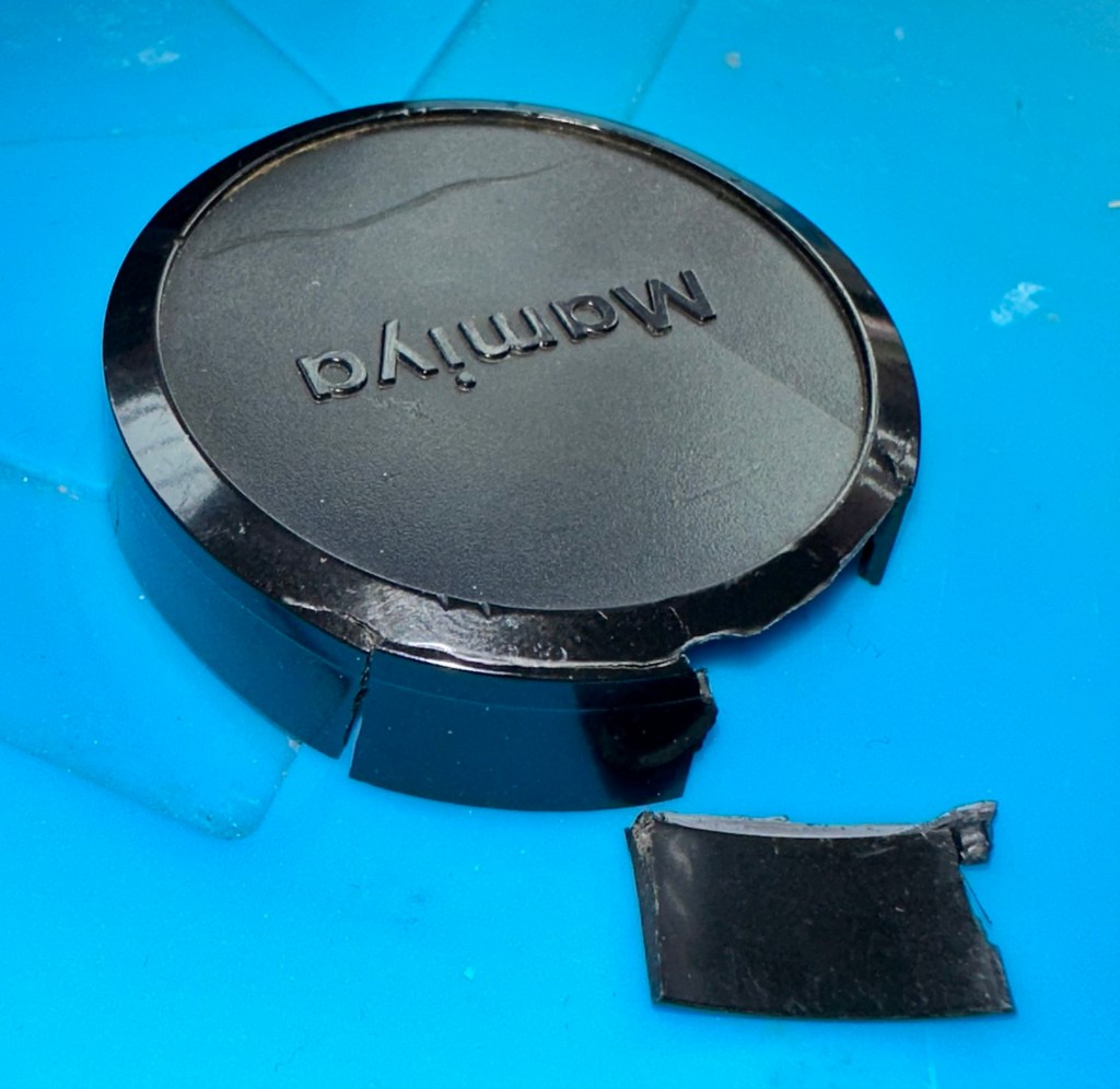
Lens caps with these cameras are very rare, this one has one and it is the original, and i suspect (from what I see in the picture) that there may be a small crack on the side of this one, but that is not an issue. This lens cap is integral to this cameras operation, as when it is placed over the lens, it turns off the camera, without it the camera remains live at all times, and would soon lose its power. It is an early power conserving device if you like. The camera looks to be in overall good condition, probably down to being stored in its original case.

You can view a lot more than I could ever tell you, just by watching this review by Mr.50mm that was posted earlier this year.

Excellent recent review

Since reading up a little on these cameras it appears that I may well have bagged a bargain, if it ever works. And I also believe the seller may well again be unaware of the operation of this camera and it may in fact be working just fine? Who knows? I have my suspicions but we will just have to wait until it gets here for assessment.

Below are some sale prices relative to this camera model that are currently selling on EBay, some extremely high prices compared to what I have paid today:

Current selling prices for this model

It’s plastic and so 80’s. And people obviously loved it. I’d like to be able to get this camera working again, and would love to run a roll of film through it to give it a test run. But first I have to assess it and see just what is wrong with it. I have a roll of old film available to test its “faulty” rewind system, and I have all my tools ready to crack it open and get inside, if I have to. So let’s get at it….

Assessment:

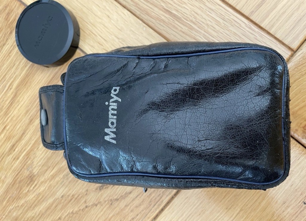
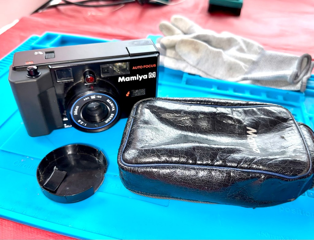
It’s arrived and I must say it is in an excellent cosmetic condition, probably down to being kept in its original Mamiya soft case. The lens cap I thought had a crack in, is actually broken, probably beyond reasonable repair, but at the moment that is not important. Let’s put that to one side for now.

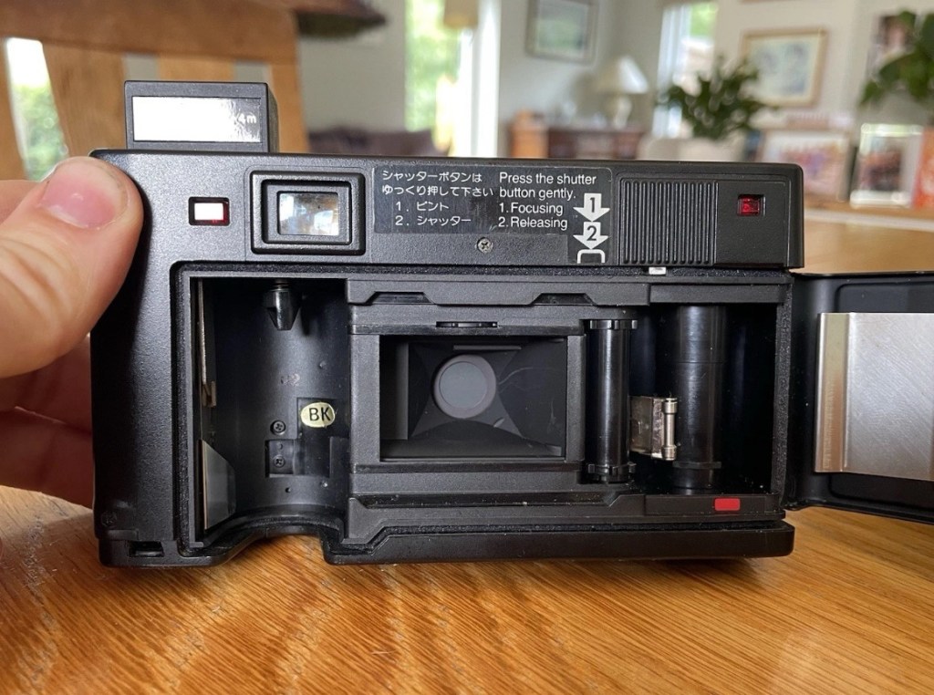
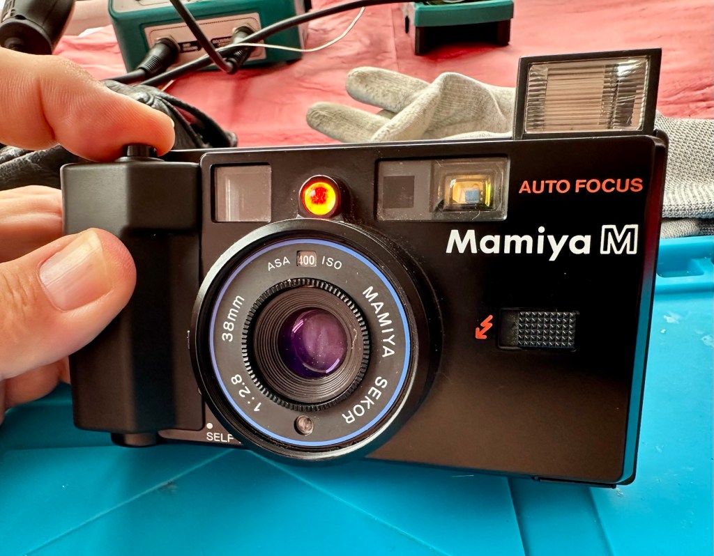
The actual camera is partially alive. When batteries are installed there is a red light that appears on the right rear side of the camera, this is the film transport light and should extinguish when transport is complete. The flash switch sticks a little, and when the flash is clicked into position the distance sensor light on the lens activates however the flash does not charge. The winding system is inoperative and does not auto wind at all. The shutter does not operate, despite the shutter leaves being able to move when gently coaxed.

There seems to be partial electricity throughout, this could very well be the issue. There just doesn’t seem to be a uniform continuity throughout the camera. This will need to be looked at. Something very weird is going on inside.

Repair:

I’m really annoyed, closer inspection shows there are 6 screws missing and someone has been inside this camera prior to me. Again I think I’ve been stung by the EBay curse of “Spares and repairs- no returns” will I ever learn?

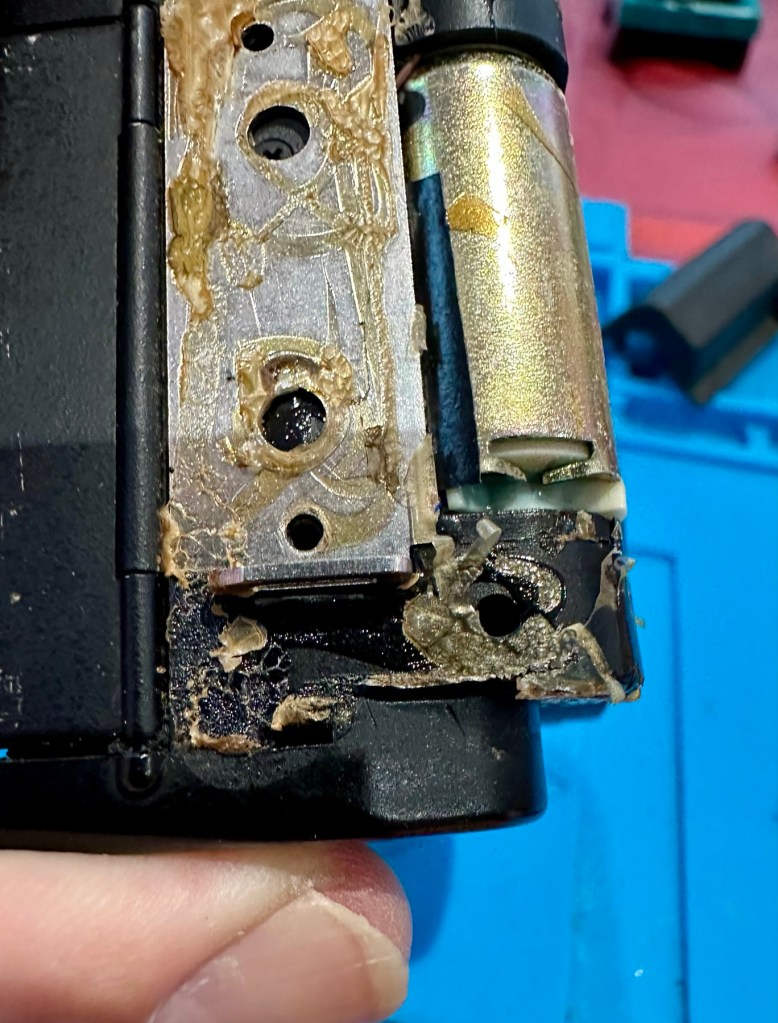
I’ve removed the remaining screws, and had to peel off the rubber grip to access and expose the motor and associated component board in this area. There will need to be a lot of cleaning here before gluing it all back in place.

I’ve managed to get the flash charging light illuminated, and a current of 214v in the flash confirms that the Flash capacitor is holding a charge and more importantly, receiving a charge from the battery circuit. But I cannot get it to fire. There seems to be an issue with the shutter mechanism and the related electrical circuit in this area. The motor is not working, it’s either dead or not receiving power. I need to look in this area a little more thoroughly.

Front fascia removed

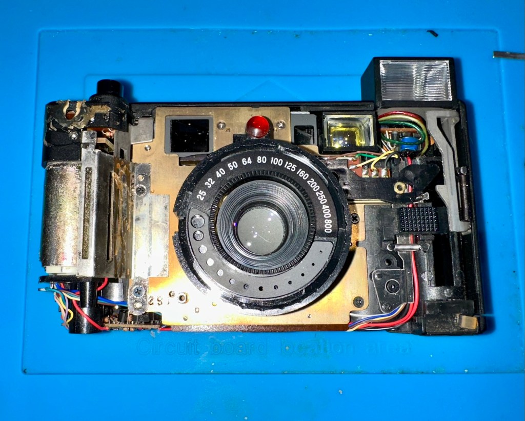
I’ve now removed the front fascia and now have a good view of the overall workings inside the camera.

Ive taken out the lens and the leaf shutter, these seem ok and are working freely when operated. To me it looks as if the mechanism that triggers the leaf shutter is either seized or the variable capacitance system located at the top of the camera, that is basically just a needle on a circuit board connected to the focus light, could be at fault, it does not freely move on each camera actuation as it should, and this is not a readily available part.

That faulty part of the board
Misfiring- faulty

It seems the deeper I delve into this camera that I am finding more issues, and I’ve just found two parts that are incorrectly installed that are on a cog system connected to the motor. I’m fighting a losing battle as it appears the person who has been here before has probably added to the issues of this camera in their attempt to fix the original issue.

On top of the missing screws I’ve now found a missing capstan cog related to the leaf mechanism that would help explain a certain lack of movement in areas. The motor is dead, I’ve taken it out and used the bench power supply and it is non responsive. Even after spraying with some contact cleaning fluid and sitting there spinning the axis to get the solution absorbed, there is still no response. It’s totally dead and will require replacement.

Result:

Well. Once again I have been mislead by incorrect descriptions on the auction sites. It’s a shame really as this is a lovely camera and if it had not been tampered with inside, I’d probably be posting a different review today, one that would be more positive. With screws, cams and cogs missing I was pretty much set up to fail here.

I’ve reassembled the camera and it is now back in its pouch. The positives are that I have learned a lot about how this camera operates, and just dismantling and reassembling the camera allows you to learn a lot about it, and the technology used during that period in time. All the screws that I removed have gone back into place with none leftover, yet another positive.

So it’s a failure I’m afraid, but it will be kept and either used as spares or I will obtain a suitable donor to get this one up and running, it will not be disposed of in any way. It will be reused. I’ve only paid a small amount for this, it’s worth it for the spares alone.

I have already set up a notification on the auction sites for when another suitable camera becomes available. I will update this post or post a new one that incorporates either the repair of this unit or its use as a spare parts donor, when that time comes.

Thanks for passing by. Its appreciated.

MB – Simon

Remember this? Everyone had one around 1978 apart from me that is. Well, now I’ve got one, only 47 yrs late and it doesn’t work. But hey that’s what this site is all about, and that’s how I roll. Always late to the party, and even then you’ll probably find me in the kitchen 🥳

What the listing said:

Cosmetically in very good condition but does not work. Please see attached pictures to judge condition for yourself.

EBay

The guy was after £17:00GBP and that included postage, but I put in a cheeky bid and managed to get it with postage for £9:80GBP. Anything under a tenner is good in my eyes.

Here’s some history:

Simon is an electronic game of short-term memory skill invented by Ralph H. Baer and Howard J. Morrison, working for toy design firm Marvin Glass and Associates, with software programming by Lenny Cope. The device creates a series of tones and lights and requires a user to repeat the sequence. If the user succeeds, the series becomes progressively longer and more complex. Once the user fails or the time limit runs out, the game is over. The original version was manufactured and distributed by Milton Bradley and later by Hasbro after it took over Milton Bradley. Much of the assembly language code was written by Charles Kapps, who taught computer science at Temple University and also wrote one of the first books on the theory of computer programming. Simon was launched in 1978 at Studio 54 in New York City and was an immediate success, becoming a pop culture symbol of the 1970s and 1980s.

Wikipedia

From what i can see in the pictures the item seems good, cosmetically. I may be able to see just a little contamination around the battery contacts but I can’t be sure. It worries me when i see a picture that shows a screwdriver alongside the item you are buying, it just screams at me that the seller has been in side and is not being truly honest about its issues. Let’s just wait until it arrives to do a full assessment. I’m genuinely excited about getting this working, as my age veers ever closer to the higher numbers. I need something to stimulate my mind, what’s left of it. 😂

Assessment:

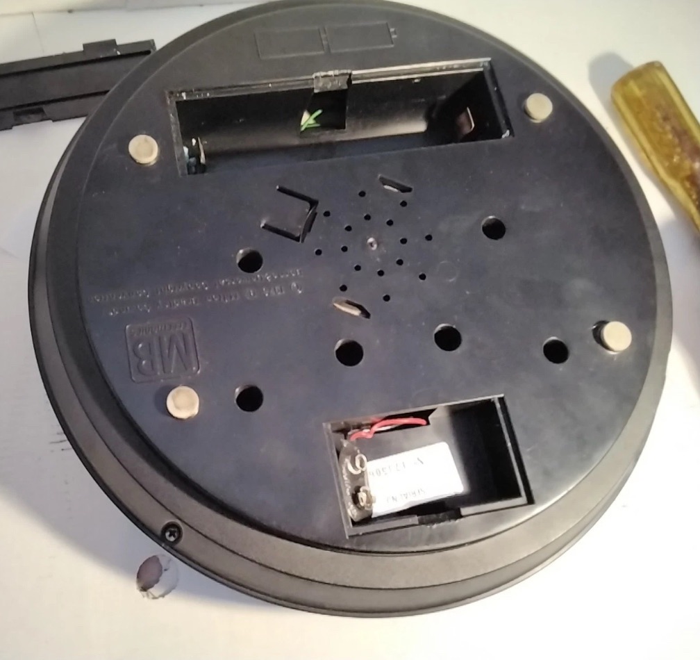
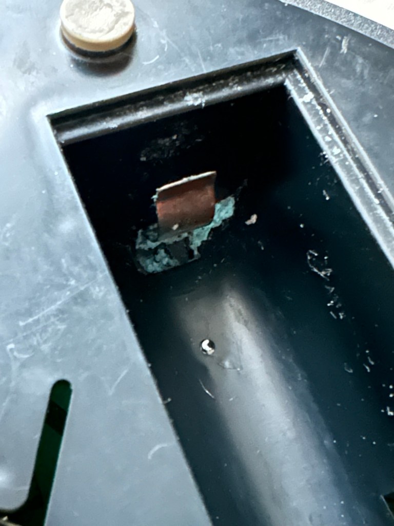
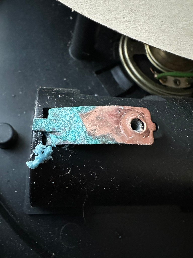
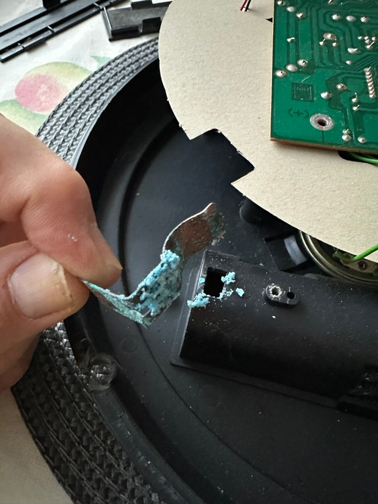
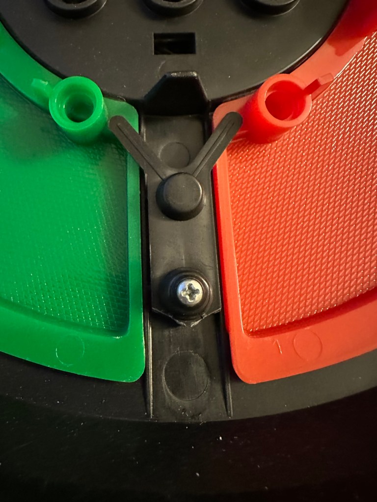
The unit has arrived and on first impressions looks clean and tidy cosmetically. The pads are not very responsive and the battery contacts are seriously corroded. The unit is a power hungry beast, taking two ”D” cell 1.5v batteries and one PP9 9v battery. The unit does not work with its batteries in place, and i’m not surprised really, and to round it all off two screws are missing from the case, and one screw mount is broken. All four plastic springs that sit under the coloured pads are broken, and just to clarify someone has already been in here and it doesn’t bode well. My previous concerns of a screwdriver being in the original photos have been confirmed. It’s been tampered with.

The board is a typical of many circuit boards from this era that were produced for MB. I had a similar circuit board on this item here: MB – Computer Battleship

In the picture above you will see two arrowed points. These points are the power contacts that make contact with the two seriously corroded battery contacts you can also see above. No wonder there is no power getting to the board. I suspect this might be the cause of our electrical problem.

Repair:

First thing to do is to get those battery contacts cleaned, as well as having a good clean of the main board. This has now been done. I’ve repaired the broken screw post by simply using a rubber washer that has been sufficient for this repair.

Contacts before and after

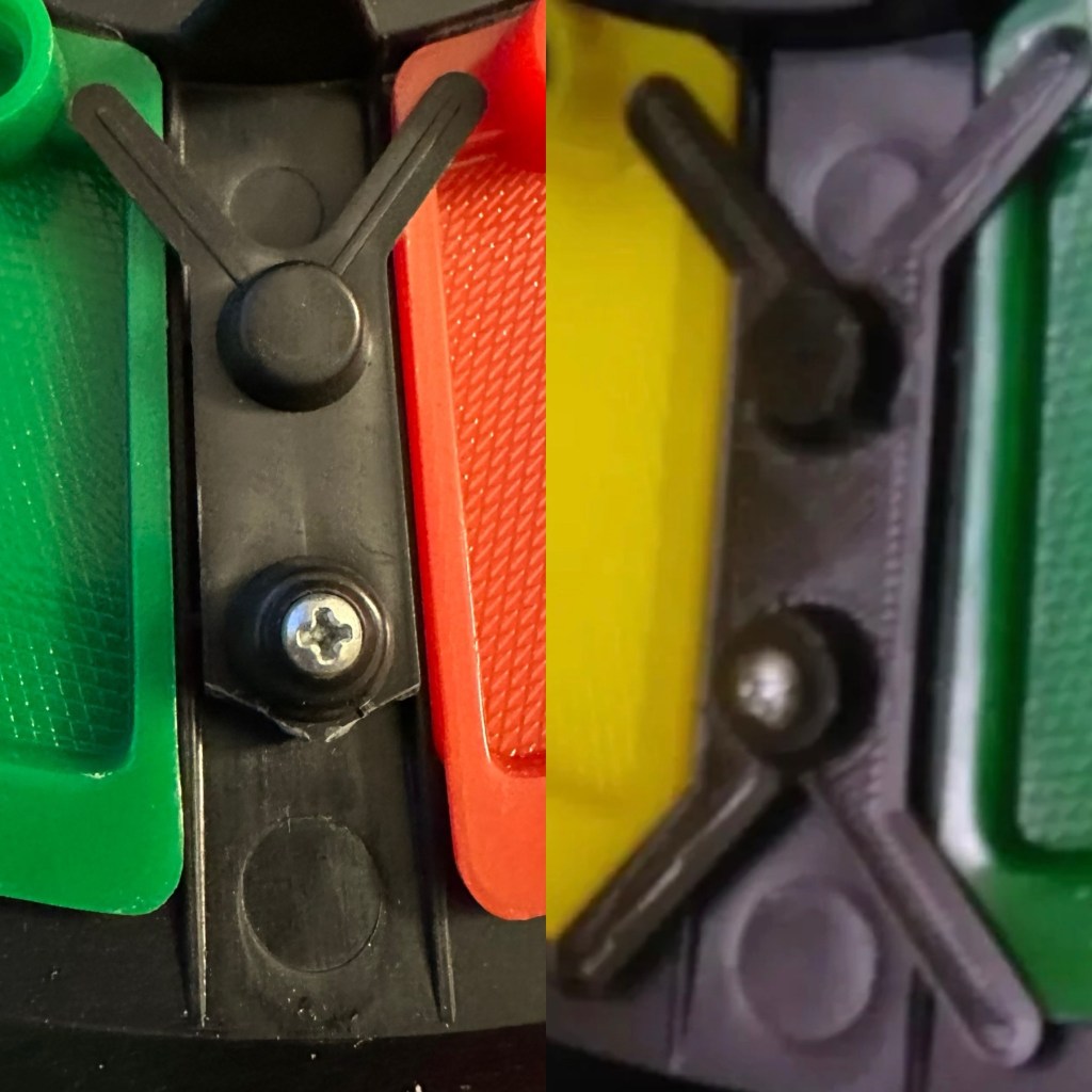
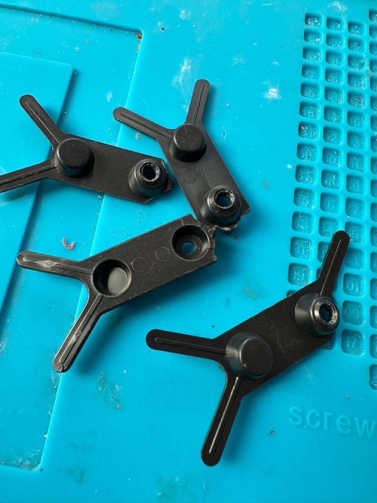
A friend of mine has kindly offered to print me off four of the “Double Y” springs to replace the ones that are already in place and broken. He owes me a favour or three and needs some subject matter to run through his new 3D printer so I’m very pleased to help him, as pending the outcome I may well buy one myself, as I have been threatening to do so for a while now. This should sort out the issue of the unresponsive pads, first found in the assessment of the item. He’s panicking that they might not be smooth and beautiful, I’ve told him not to worry as they are hidden inside anyway.

What I currently have on the left, what I’m expecting on the right

He’s just supplied me with five double “Y” pieces just in case one is damaged in some way. Let’s get these put in place to see the difference these make.

With the new springs in place the pads are working as they were originally designed to, now with some springiness in their operation. The battery contacts have now also been put back in place.

Cleaned contacts back in place

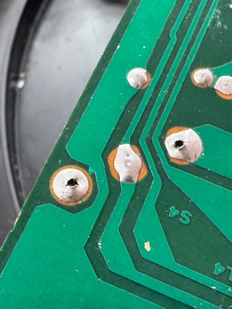
When assembled, the buttons are a little erratic and not always responsive so I decide to look into this further. A quick Look at the board shows that the solder contacts on the board for all of the button connections are worn, the solder has failed so I decide to reflow all these solder joints to improve the contacts. This appears to have worked as the unit when reassembled, now has uninterrupted operation. This is an age related issue. A simple fix.

Result:

Another 47 year old saved from the scrap heap, it’s been an interesting and sometimes confusing repair and I thank my friend who stepped in to save the day by utilising his 3D printer to make some parts. Without his assistance this repair would not have been achievable.

It’s just another old piece of retro history to add to my ever growing collection and much to my wife’s dismay. Bless her.

Now working

Thanks for passing by, as always it’s very much appreciated.

Failures and time wasting

Morning all, I hope I find you all well. I must admit I’m only dipping in here at the moment to see what’s going on and to update some old posts. I currently have 16 posts in draft and that’s down from 21 a couple of months back, so I am actually starting to clear the backlog if not at an exceptionally slow pace.

About right….

Failure: I deleted one project last night that had been in draft since May of last year, it was a work in progress and I was hoping to complete it last night when I confirmed the issue was terminal and there was no way it could ever be fixed. It’s a shame as it was a big post and I had learned a lot from it but it just wasn’t to be. I’m not happy at spending so much time on a project just for it to be a failure, and you good people don’t need to see that either. So I’ve just put it down to experience and chalked it off. Today the whole project will be dismantled and parts will be salvaged with the absolute minimum going to scrap.

Time wasting: I don’t know if anyone else out there has experienced the estate agent tourist phenomenon. We’ve had our house up for sale about two weeks now and have so far had a number of people allegedly showing interest. I say allegedly as I think the whole estate agent “thing” is farcical. There used to be a time when you had to prove to the estate agent that you had the funds, or your own property was itself on sale before viewing a property on their books.

Well one of those people who “Viewed” opened up to me by saying he had no intention of buying our house, he didn’t want to buy any house, he and his wife have days out where they just pick an area and go and have a nose around other peoples property. Yes, for them it’s a bloody day out, just like you’d visit a stately home or a pub, they just go to nosey around peoples homes, with absolutely no intention of buying.

To say this kind of boiled my piss is an understatement. The estate agents really got it that day. The bloody cheeky sods. I suggested they sell tickets and maybe we could sell ice creams as the clients came through the door. I don’t think he understood my sarcasm…

Apart from all of this things have just been so busy that unfortunately word press has had to take a back seat. I still get notifications, some very annoying, considering some of my posts have taken weeks, even months to put together someone manages to read about 15 of them in about 30 seconds, serial likers, the one thing I find incessantly annoying about this platform.

Hey ho, I need to go now as you can probably tell I’ve not had a lot of sleep and I’m acting a little out of character. Time to go before I become bitter and twisted.
Have a great day.

Watch out, I’m the pilot

If you weren’t afraid of failure, what would you do differently?

Love this question, such a simple answer for me. If I wasn’t afraid of failure I’d train to be an airline pilot. I know I’d fail miserably in real life at it, and it probably wouldn’t be such a good thing for you as paying passengers, but wow, it would be one hell of a flight for me. I’m a bit scared of flying you see…

It would probably be your last flight, but I guess that’s why we always have a fear of failure, as in truth you only want a super confident individual in such a position of trust.

As an aside, we should never be afraid of failure, it’s always disappointing to fail, however it’s one of the ways that we learn to avoid future potential failures. It’s hard when you fail a task, but you are never a failure, you won the biggest lottery of your life when you were born. The odds of you getting to this point in life and reading this post are apparently an eye watering 1 in 400 Trillion.

Refer to this post I won the lottery…that day to see what I am going on about.

You’re most definitely never a failure. You’re always an achiever, a pupil of the university of life.

Happy days all…

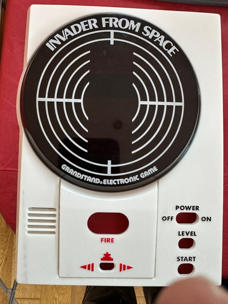
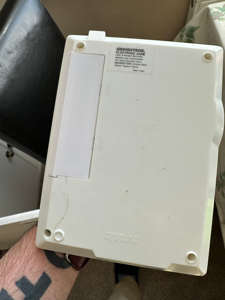
Grandstand Invaders from space game

What the listing stated:

Can’t get to turn on unfortunately. No battery cover. Any questions please ask

EBay

I know, there is no battery cover, however I have already sourced a seller of one if needed. This item looks quite dirty so a good soak might be the order of the day to get started. I’ll wait for its arrival before I jump to order any other bits for it.

Now as I’ve said in the past these units fall into that crazy price category on the selling platforms as the “New Antiques” of today. For an item that was low cost, somewhere between £25-40GBP when it came on the market, they can certainly command a wide range of crazy prices, here is an example of price ranges from today:

The massive range in prices for these units

This one I purchased today only came up for sale about 3 hrs ago and I thought it would have been snapped up by now, it hadn’t so I didn’t hang around any longer and purchased it for a total of £16:38GBP including its delivery. I’m not going to get too smug yet, as for all I know I may have just purchased an empty shell. Let’s wait until it arrives.

Here’s a little history of this unit:

Grandstand “Invader from Space” is a tabletop LED game dating back 45 years to 1980. Four ‘AA’ batteries power the unit or, alternatively, the Grandstand 5.5V@300mA power adapter (or an equivalent power pack) sold separately. The game, licensed to Grandstand, is a copy of Epoch’s “Invader from Space”

The company initially behind the “Grandstand” label was Adam Imports Ltd., (from 1980 Adam Leisure Group Ltd. and by 1983 Adam Leisure Group PLC) founded in 1973 by Chris Rycroft and Les Kenyon of Harrogate, UK. The company initially started as a mail order company and was the single largest supplier of calculators in the UK by 1974. By August 1978, George Bassett had acquired a 75% holding in the capital of Adam Imports for £750,000 cash, plus 60p in the pound of profits before tax in excess of £500,000 for year to December 31, 1978. Adam Imports was re-acquired from George Bassett by Chris Rycroft in 1980. It chiefly imported electronic products from other manufacturers such as VTech, Epoch, Tomy & Entex, selling them in the UK re-branded under the Grandstand name.

Wikipedia and others

So that’s the history

There is a good link to a similar repair on YouTube from a guy I follow named Stez Stix Fix, it’s very much worth a look and he has a great if not sometimes crazy way of diagnosing and repairing items. A cool guy though.

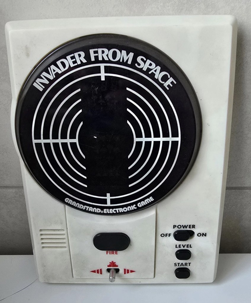
The Grandstand invaders from space game

Anyway back to my own purchase.

Assessment:

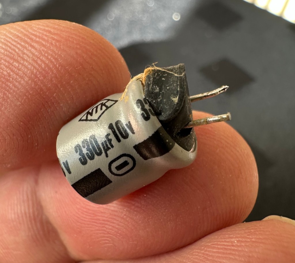
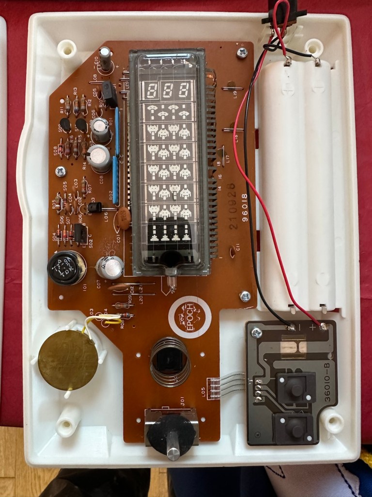
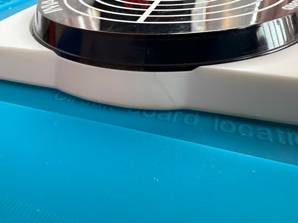
I must admit the unit doesn’t look as dirty as in the original pictures. The battery cover is missing and there is a crack in the side and a deep scar at the bottom, this won’t be too much of an issue if I can weld it all back together. I will still give it a good soak to clean it all up though. I’ve put four batteries in place, and the unit is definitely dead. There are no loose wires, voltages are getting around the board according to the multimeter and nothing is getting hot. There appears to be no short circuits, and then I notice this, capacitor CO7, slight bulge on top and what looks like leakage from the bottom. We have a candidate as to why this unit is not working.

CO7 looking unhealthy to me, you can see the component to the left that looks like it’s covered in a fur ball. The result of the old capacitor “coughing”

I’ll whip this out and see what we have but I suspect this old capacitor has failed and is causing an issue, heres hoping I have a suitable replacement.

Repair:

This little beast is a 330uf 10v electrolytic capacitor. I have none available so have had to purchase a pack of ten. These should be here in the next few days. There are three other old electrolytic capacitors that I will also change whilst I’m in there, as these are all likely to fail at some point soon. These components are now all around 45 years old, it’s a wise move to change them out.

One very dead capacitor removed.

I’ve ordered a 3D printed battery cover to replace the one that is missing. This should be here in a couple of weeks.

Whilst waiting I have cleaned the inside and outside of the casing as best I can. I still have a piece of broken surround to repair, however this is just a simple glue and a little bit of support job.

Broken surround repaired

The surround that was broken has been repaired and secured with some nylon soaked in a superglue compound inside the casing. It’s rock solid. Outside the break is hardly noticeable. The break is secure and much stronger now.

New capacitor here

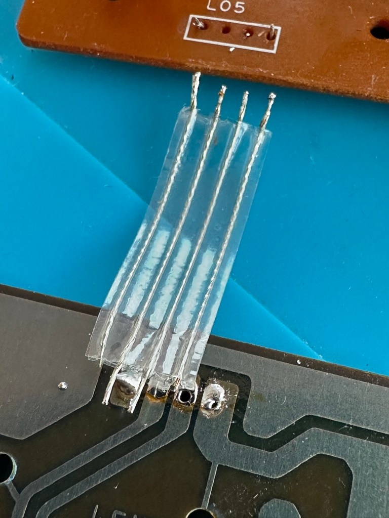
I’ve replaced all the offending capacitors and the unit remains dead. I’ve reflowed most of the board as there were some dry solder joints. I’ve also rewired the bridge from the control panel to the main board as one of the wires here had broken.

Bridge required resoldering

After using the multimeter to check some traces and components it’s now pointing to this component (a power transistor D882) being the cause of this catastrophic breakdown as its readings are all over the place. I suspect this item has overheated, the capacitor has blown and then it’s just died itself. I’m probably wrong, but I know what I mean. Probably just a catastrophic chain of events that all contributed to the units demise.

D882 transistor – power regulator

And as usual I have none available so will have to send for some new ones. The new components have arrived and the new power transistor has taken its place on the board. Now reassembled I place some new batteries in and the unit comes to life. It was the power transistor at fault, I should have really checked here first after seeing that damaged capacitor at the beginning.

All old components removed and replaced in this unit

Not to worry though as it’s had a good overhaul and has been totally recapped as a precaution. I’ve used some conformal coating on a few tracks that had some copper exposed after a good clean, to ensure they don’t deteriorate any further.

It has life

The unit is looking really good and these items were traditionally very loud and this certainly is. It’s working well just as it should do and I’m exceptionally happy with this repair. I’m still awaiting the battery cover that I have had 3D printed and this should be here in the next week to complete the fix.

So with that I will bring this build to a conclusion. It has been a fun project, I’ve learned a number of things about this circuit board and gained valuable knowledge.

But best of all we have rescued another item and saved it from landfill.

Winner 🥇 👍

Thanks for passing by

To be the best version

What was the hardest personal goal you’ve set for yourself?

That’s easy. It’s to be the best version of me I can possibly be. It’s what everyone I know and love deserves at the very least.

And I continually fail.

I’m not very good at being the best version of me.

I won’t give up though, you’ll just have to put up with the current version until the updated version comes along.

Sorry about the delay, it’s just so damn difficult at times, and when you think you are getting there something knocks you back.

That’s life, it’s a series of walls put in front of you that you have to climb. It’s just the walls are now getting more difficult to scale.

Peace to your lovely faces.

Realistic drawing

What skill would you like to learn?

I love art, I love to draw I love to paint but realistically I am crap at it.

My father, both sisters and both brothers were so artistic but me? No. I just can’t do it. But I love it.

I often wonder if other people over time, artists, that is, were also crap . So crap that they invented such art forms as cubism and such. I’m not in anyway calling myself an artist, a P*ss artist maybe but never an artistic fellow.

I have lessons, I attend art classes but I just don’t cut the mustard. I guess I’m just destined to be one of life’s tryers.

I’m sure I’m probably beyond learning now, god knows I’ve been trying long enough. However I enjoy it, it keeps me calm and relaxed, and that’s not such a bad thing.

I just wish I could draw.

Have an arty day everyone…

Sony Discman D-121 Pt:2

Assessment and fault finding… will it work?

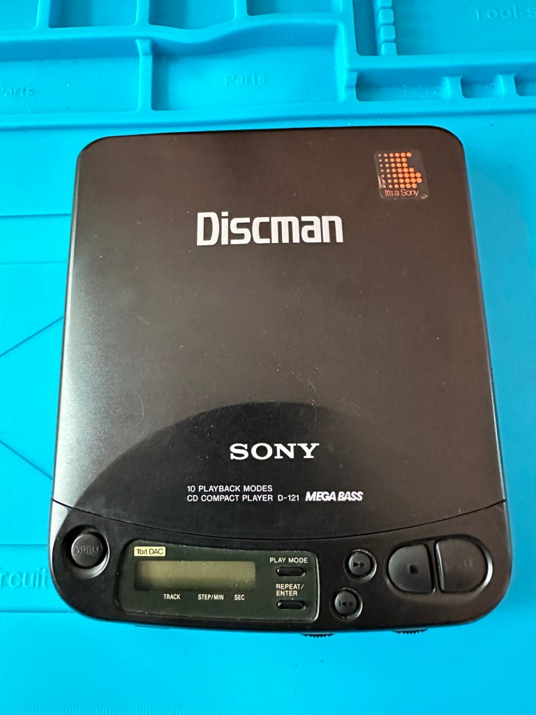
My recent purchase of a Sony Discman D-121 from EBay has arrived. Just as described it wasn’t really working so I decided to give it a once over to check condition.

Cosmetically sound

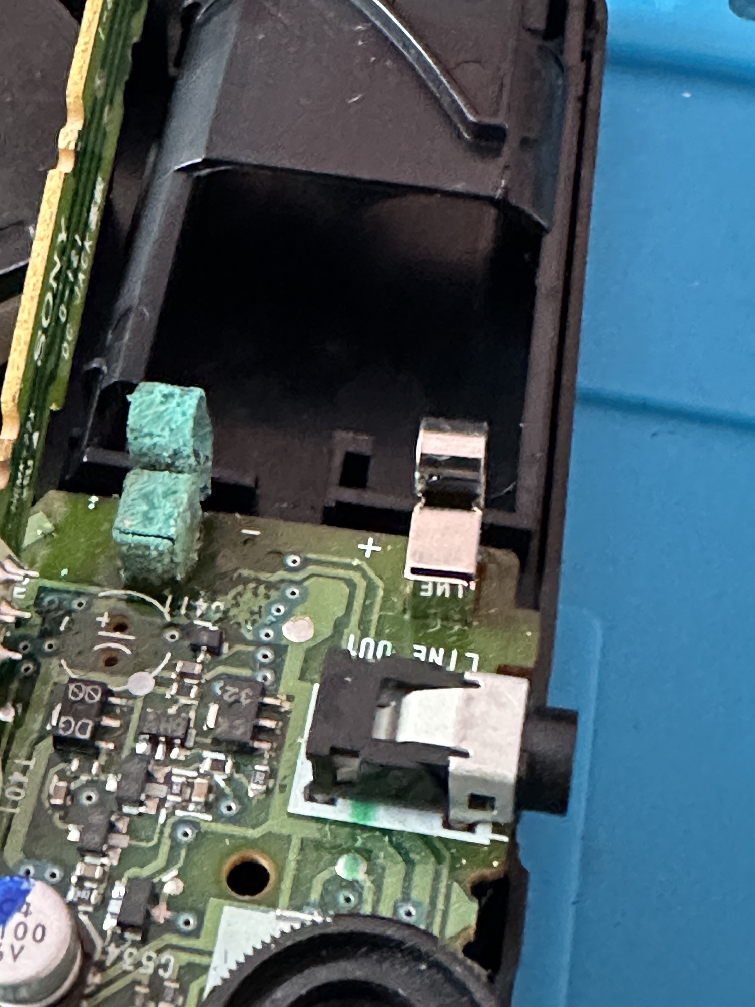
Cosmetically it’s in very good condition, open the battery compartment and it’s a different story, definite signs of corrosion and at this point I’m thinking the worst. I put two batteries in to check, the display comes on and shows some strange indication of “HI VOLTS” even though all I have are the two AA batteries in. Strange.

I do manage to play one song but that’s it, any slight move and it skips and hops and shows a raft of other error messages that don’t Instil any confidence into me that this is going to have a good outcome. Then the CD drive motor breathes its last. That’s it….kaput.

So I open up the unit, and put the circuit board under the microscope. The area around the corroded battery terminal has progressed on to the board and a couple of the circuit board tracks have been totally destroyed. A few components look to have issues and have some spurious test results. A check for continuity with the multimeter confirms that one track is dead and another is intermittent at the very least.

Under the microscope

I clean the offending section of the circuit board with IPA and this just confirms the issue, but at least it looks cleaner. If this had been the only issue I’d have happily soldered in a couple of thin wires to the undamaged track to ensure a reliable continuity.

A further look around the board, and there’s nothing blatantly obvious, but seeing this unit was produced in 1993 it’s now in its 31st year of use I also suspect the capacitors (of which there are many) may well be of that era of suspect capacitors I discussed on a previous post. Read here: Capacitor plague

The main drive motor is known to fail after time and a sure sign is if the CD jumps when moved off the horizontal, apparently this is due to bearings becoming misshapen due to use.

This unit therefore is beyond economical repair for me, and I’m not going to progress it any further. The good news is that I can use the unit for spares and as a number of these older units have interchangeable parts, I’m hopeful that as I have a few more units turning up later this week they may have a willing donor.

So the recycling goes on, and that’s always a good thing.

Happy day to you all.