Modified Sega game gear 2110-50

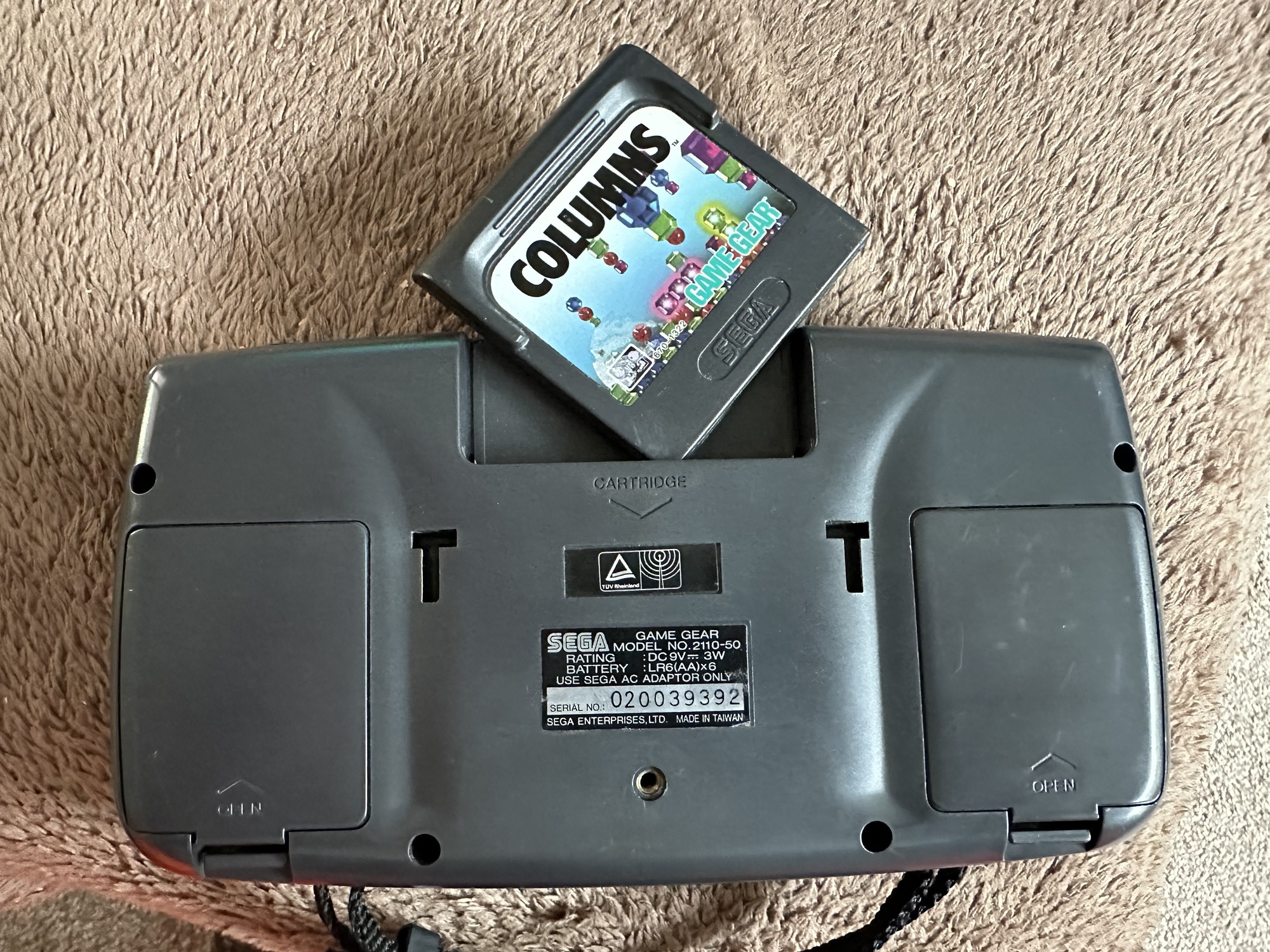
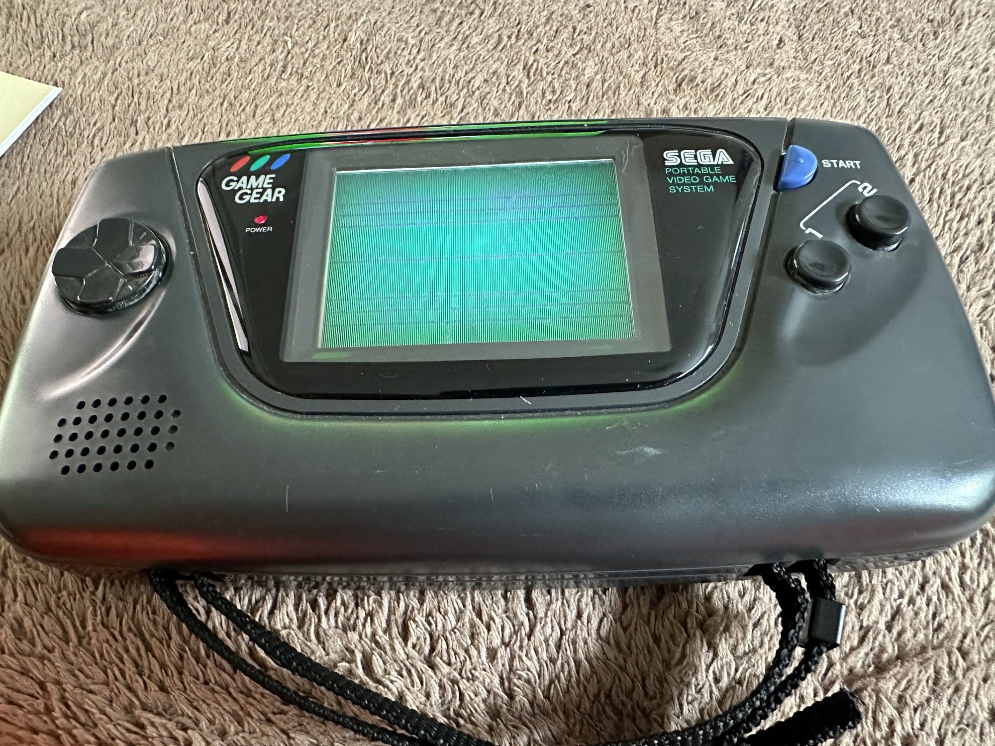
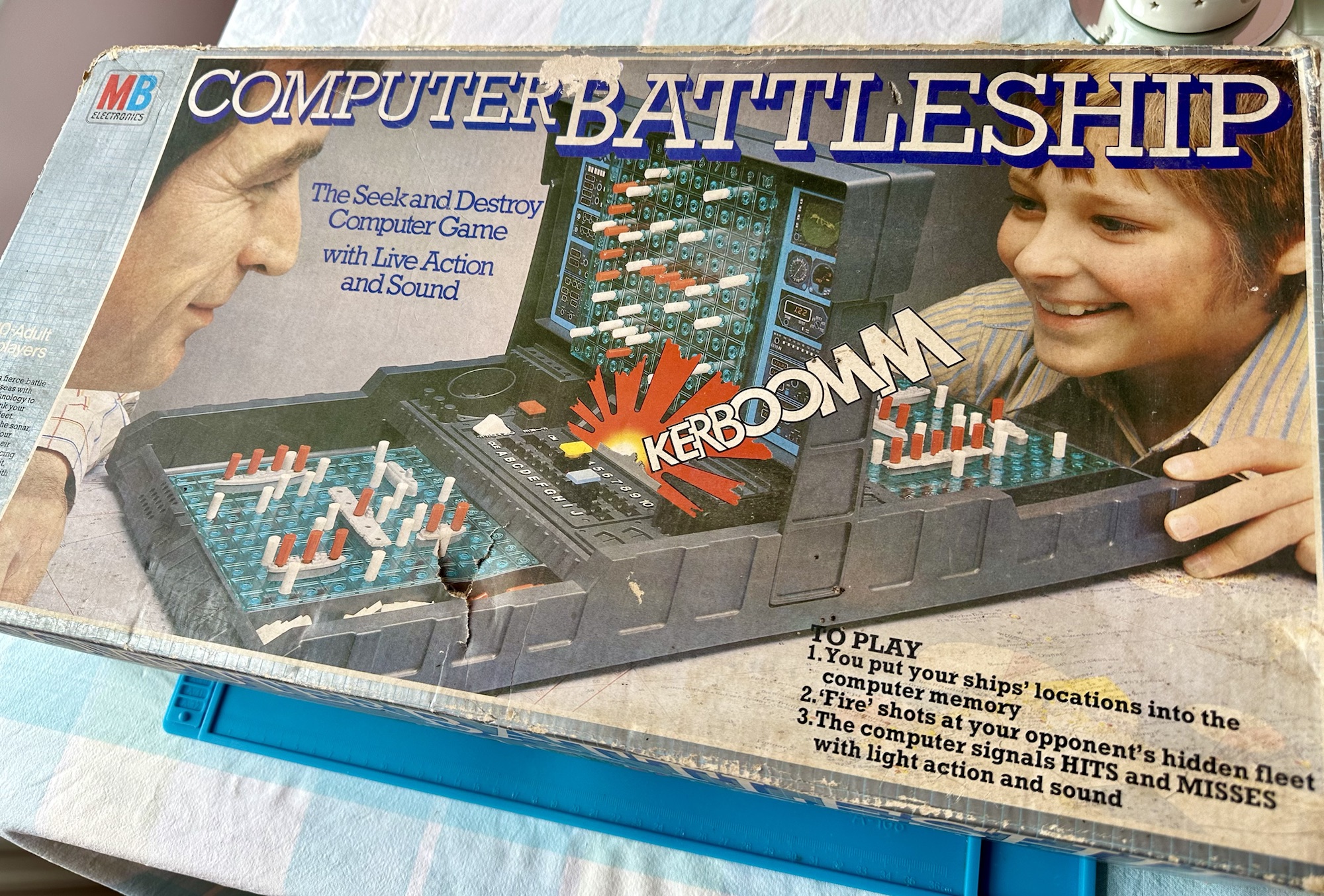
You may wish to refer to this post: Sega game gear 2110-50 where I purchased a non working Sega Game gear and brought it back to life.

The (I thought it was repaired) Game gear

I’m now ready to do some modifications on this unit, and I will save the replaced items for use on later projects.

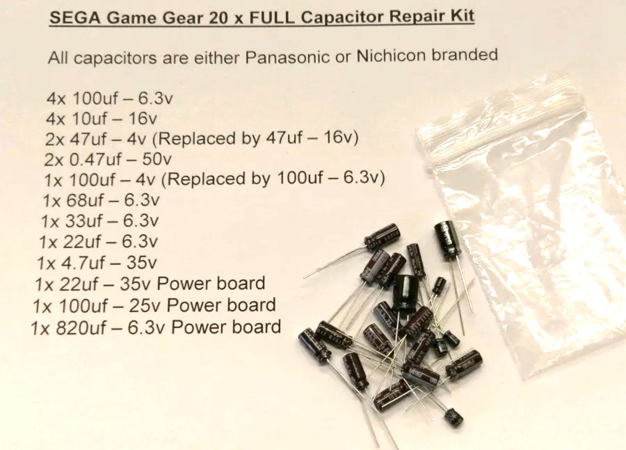
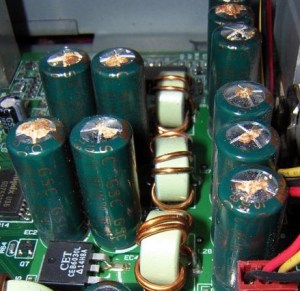
Pretty much every Game Gear that was ever produced (and that is approximately 10.6 million units) has suffered with the dreaded (Capacitor plague) that I have discussed in an older post. The first job that is recommended to be carried out when purchasing an old Game Gear is to replace the old capacitors, it’s quite an easy task and nine times out of ten will remedy any issues that you have and allow you to continue gaming for years to come.

However there are other issues.

The screen is an old tube powered system that is exceptionally power hungry, you can replace this with much superior LCD versions, I’m withholding from doing this at the moment as I want to get as much use out of the old screen, and to be honest my unit doesn’t require replacement just yet, there’s still life in the old girl. I’m sure that this will be a future project though.

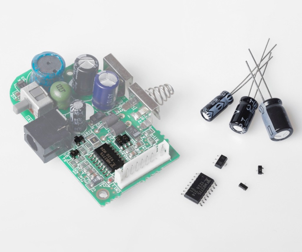
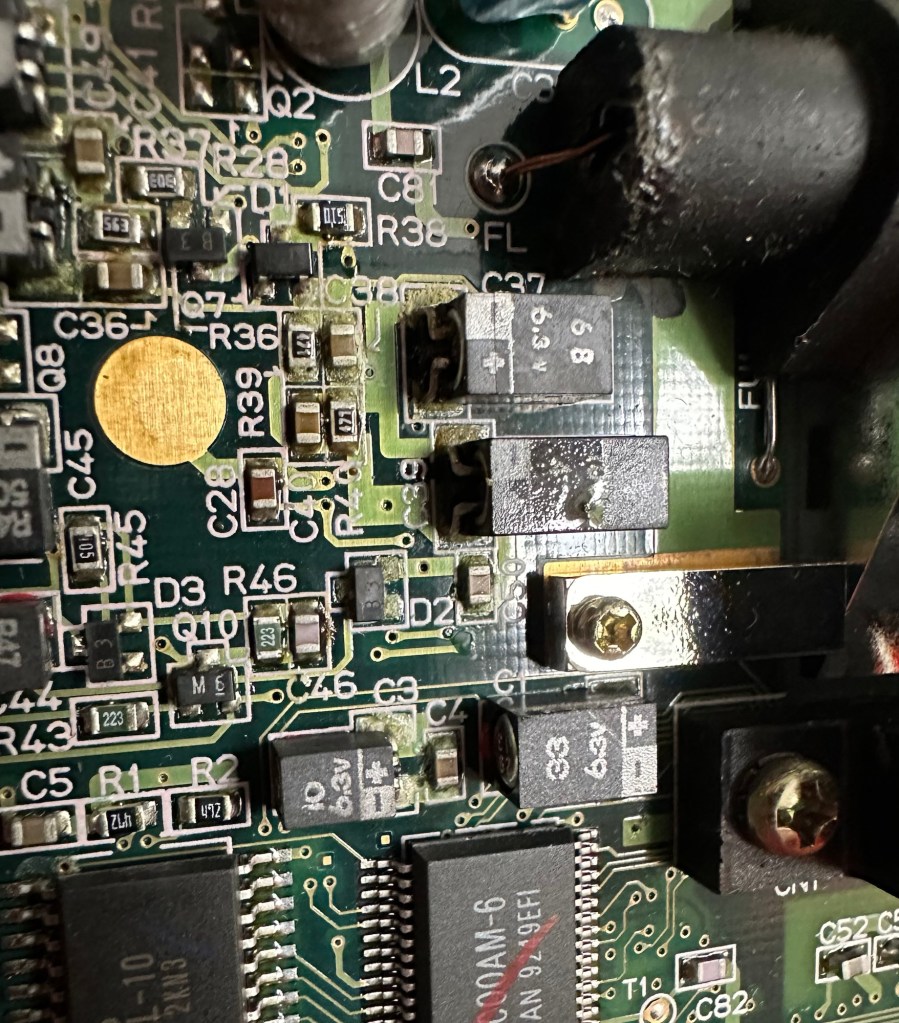
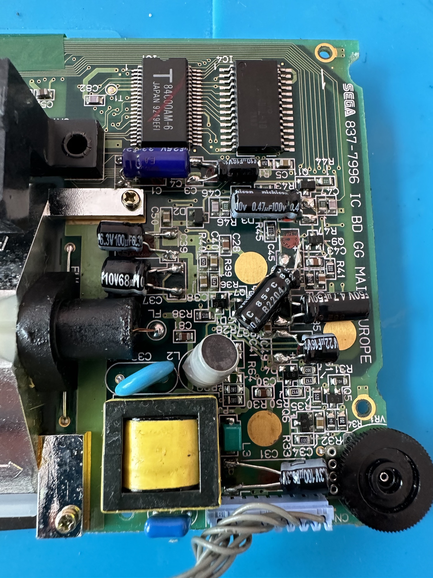
Occasionally after doing the capacitor replacement on the power board, other components such as a small IC and three transistors that control voltages across the system, start to misbehave causing the unit to switch off after just a few seconds. This is currently occurring with mine and I am intending to replace these components to see if this sorts out my issue. I have also ordered a replacement power board from China that is a fraction of the cost of a European one, it may work, it may not but if the change out of components dosen’t work at least I’ll have an alternative option.

There are a few checks we can do prior to replacement of these components on the power board that will confirm the various voltages required by the system. It’s best that these tests are done prior to diving in head first to replace them. You could be just wasting time. You may need a new power board or maybe even consider converting to a rechargeable battery system. It’s all doable.

Expected voltages – photo courtesy Retrosix

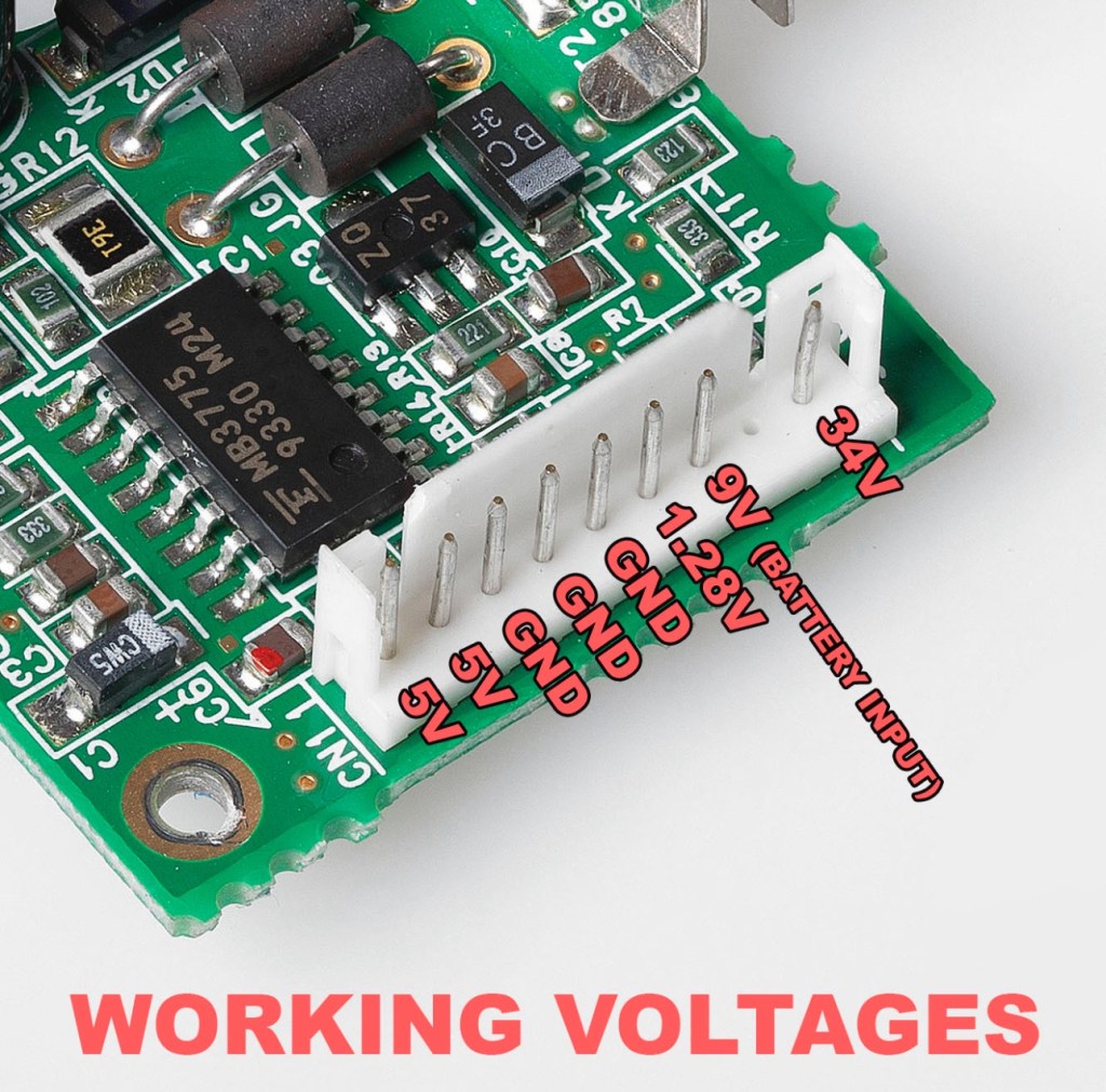
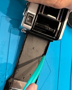
Here are the results from my test of voltages on the power board, I’ve injected 9v via a bench power supply to the battery contacts on the board:

  • At the 34v pin I had 0v
  • At the 9v pin I had 8.9v
  • At the 1.28v pin I had 1.28v
  • The three ground pins read as ground
  • At the two 5v pins I had 0v

So as a result I obviously have an issue with the 5v rail and the 34v rail, I believe the 5v rail is the one that affects the boot sequence and the 34v is not an issue at the start up, however, it’s there for a reason and this simple test proves there is an issue. I will therefore only change the IC and three transistors as the capacitors were changed when I did a full recap.

For my modifications I am getting a new clean amp duo audio board with dual speakers instead of the single mono one that is standard. This is an upgrade on the original, extremely efficient and with better sound processing.

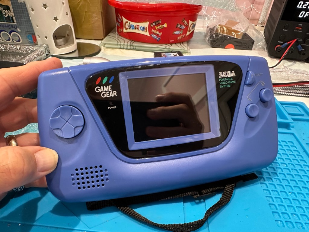
I am also replacing the shell with a new Blue case and glass to replace the scuffed old screen, this shell also has dual speaker outlets to compliment the audio board replacement. The shell is already prepped to accept a rechargeable battery system should I decide to install it at a later date.

I shall be getting these upgrades from Retrosix who specialise in supplies and modifications for gaming consoles.

All the items have now arrived and the first thing I’m going to do is sort out the replacement IC and transistors on the power board. The rest is fairly straightforward. However they have sent me the wrong shell, a single speaker one instead of a dual speaker one, so I’ve now got to await a replacement, annoying!

Scratch that, they are saying that they never did have any duo speaker ones even though they were advertising them on their site ( as per picture above..) and after a protracted discussion with the supplier / owner i’ve come to the conclusion that he might think he is a wizard at modding and designing circuitry but is totally and utterly inept at customer service, he wouldn’t know good service if it bit him in the ass. Hey ho on we go, it is what it is.

If you choose to use them in the future then just be aware. They have an uncanny knack of trying to pin their inadequacies and mistakes on you, the customer. Caveat Emptor – as they say.

So now the sound will be original mono, but hopefully improved. I have a spare speaker and mount as a result and I can use the new clean amp duo board in a mono configuration. Should I get a duo speaker shell sometime in the future I can always do a swap out.

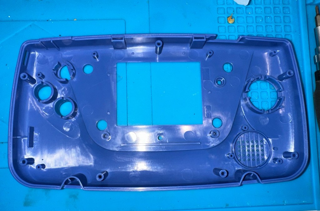
Today I’ve taken the empty new shell and installed the new audio card and speaker, as well as the new buttons and silicon pads. I’ve then installed the main board minus the power board that still needs the new components.

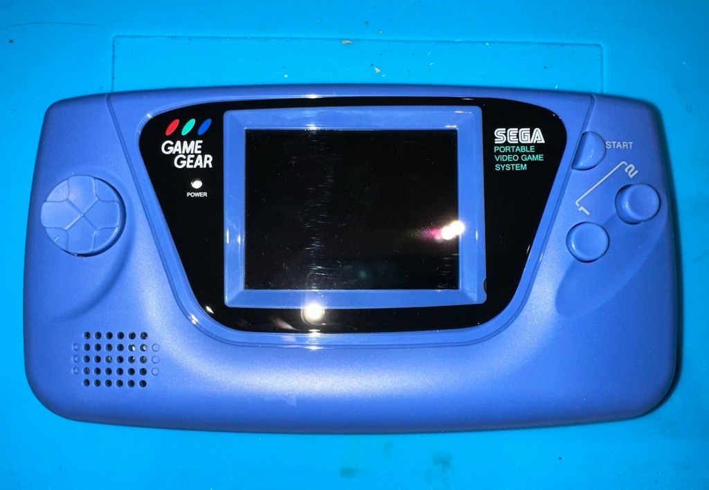
I’ve also installed the new front lens on the unit and I must say it looks nice.

New front lens on unit

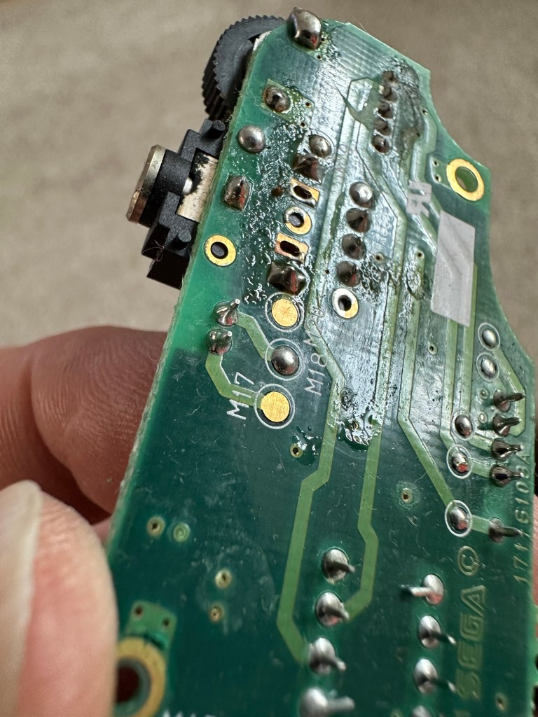
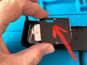
Let’s get to the difficult bit, replacing the components on the power board. I’m not joking when saying that some of these items are not much bigger than a grain of rice. I suspect a lot of bad language will be used here, as this is a new level of soldering for me. I’ve never replaced anything so small before. If I balls it up I’ll just have to await my cheap Chinese power board.

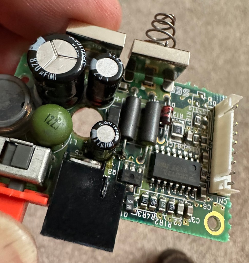
Ok, the power board from Ali Express got here really quick, to be honest even before I could set some time aside to change the components on the old board, so therefore I’ve decided to try this new board as a straight swap.

I will keep the the components and the old board to use at a later date.

First though I have used the bench power supply to test it is ok, and it’s a big tick on all voltages as per the test I did on the old board. All voltages are stable and consistent, so I have secured the board in place and put the required batteries inside. Works perfectly.

Back together, awaiting the big switch on
Working perfectly

I now have a perfectly good looking updated Game gear that I am exceptionally pleased with. The sound system is a good upgrade, it has a really loud volume (adjustable) and is crisp. The powerboard from China at a total cost of £10.80 is an absolute bargain, and works perfectly with good stable voltages. The case is good, fits well and the lens is clean easy to install and scratch free, the whole thing looks brand new.

Two old rebuilds, rejuvenated

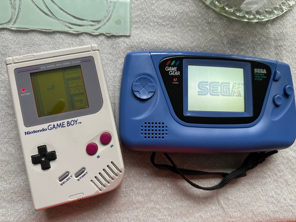
I now have two perfectly good looking and working examples of 90’s retro rivalry in perfect working condition. The plan is to display these in the house, on a custom made display. I’ve really enjoyed working on this little project and I’m made up with the outcome.

The only things left to be done would be to change the power supplies to rechargeable and to change the screens to new IPS/LCD screens, but I don’t think I’m going to do that on these two, I’m keeping them original or as close as possible to original, I want to keep these as they are, to cherish in this condition for as long as I can.

I love them. And they are fantastic.

Sega game gear 2110-50

What the listing stated:

SEGA GAME GEAR Console FAULTY

Ebay

And that was it. Faulty. What’s faulty? I’ll not know until it arrives as i didn’t ask. Foolish perhaps, but I was looking for a challenge and something I could later mod. I think I’ve found it.

I must admit I was looking for a cheap way into a retro gaming repair and I believe this was it. Most damaged game gear units seem to be averaging around the £42GBP price but I managed to get this 2110-50 version at a lower price of £28GBP (and I may have got a game with it, let’s see what arrives!). However I don’t know what the heck is wrong with it but I suspect it’s the usual issue that has plagued these 90s retro units since their inception where the capacitors fail catastrophically.

There is probably not a single one of these units out there that has not suffered this issue or is certainly guaranteed to do so sometime in the not too distant future. Imagine how many of these units have just been discarded as junk considering that 10.62 Million units were sold up to and including its discontinuation date in April 1997….scary!

The first recommendation from anyone in the know is to change the caps before they start popping and corroding everything. I have a set of replacement caps ready in anticipation.

My hope is that this unit has not yet reached that corrosion stage….fingers crossed 🤞

Hurry along now Mr.Postman….

Both Game gear and replacement Caps have arrived. And I’m really happy as there is a game in the unit as well “Columns” Sega’s answer to Nintendos Tetris. A nice bonus.

The unit turns on, there is no sound, and only a very feint green glow when the unit is held at an angle. It’s looking very much like it is the old Capacitor problem.

The unit is in surprisingly good order with scuffs and minor scratches as you expect from a game that’s around 30yrs old. The lens scuffs aren’t an issue as a new lens is relatively cheap. But that isn’t the problem as it stands. Let’s get it working and I can worry about that later in the repair process.

There are no signs of any corrosion in the battery compartments and this pleases me. I only hope that when the unit is opened there are no obvious signs of corrosion on the boards.

Wish me luck, I’m going in….

Overall I’m happy with the condition inside, no bad corrosion, however it’s noticeable that a few capacitors have leaked. The worst seems to be C39 on the main board, it’s easy to see the residue.

Main board Capacitor C39 leaking

This unit separates into three boards. An audio board, a power board and the main board. This is a twin asic board, I have removed the audio and power boards as these are the first and possibly the easiest for me to be working on.

The audio board has 5 capacitors that require replacing, I can see some leakage on the rear of board but not in the area of the capacitors. I suspect that this is factory flux though I could be wrong. When I remove the caps I’ll clean all the pads and use IPA to clean so this should sort that issue out.

Audio board Leakage or Flux

The power board only has three Capacitors that require changing, however it’s clear to see here that C5 has been leaking.

Powerboard C5 leakage

Let’s get on with the removal and replacement of these 8 components. The other 11 are on the main board.

Well that didn’t go too bad. A few minor position changes due to the capacitor types being a different size on the board compared to the 1990s version.

It was obvious that there had been leakage on these two boards due to the fishy smell that arose when the soldering iron was used. That said, the old capacitors came off without too much problem. I used solder braid to remove the old solder and then gave a good clean of the board with IPA prior to re tinning the pads prior to putting the caps back in place.

I knew there wasn’t a big issue with the power board as this was sort of working prior to this project. This was the easiest board to solder as it had through the board components, pretty much a straight swap but for better components.

The audio board was different as I had to reposition these pots so the case could close properly and the shielding could go back into place with no issues. Again I used the same process of unsoldering, cleaning thoroughly and then tinning the pads.

These two boards are now complete. As a test I thought I’d reassemble the unit and see if there was any improvement. Power came on and the red led lit, this was a good sign that there was power and I’d not messed anything up. Secondly there was sound, we didn’t have that before so this is a definite improvement on what we originally had. Volume works with just a couple of occasional crackles so I may have to use some more contact cleaner here.

We have sound

So far, so good. No real improvement to the picture even though you can see something is trying to come through. That said I’m hoping the replacement of the caps on the main board will help this. So with no further a do, let’s get the main board finished.

Just got home from work, now time to get these last 11 caps done. All the old ones removed, all the pads wicked to remove the old solder and what a stink of old fish, these capacitors had definitely died.

All cleaned with some IPA to rid of all the debris and then fluxed and tinned the pads ready for the new capacitors to go into place, I’ve got this off to a tee now and these went on a lot quicker, easier and tidier than the last lot. I’m a lot more competent now, and feel more confident with this process.

Had a little trouble getting it all back together, a couple of the new caps had to be tweaked slightly as they were in the way of a screw post, the earth shield was also causing issues and shorting the system, again a bit of captain tape helped shield an exposed component. All this done I put the strap back on and loaded up the batteries. Switched on and red light, all looking good…

All working

Very happy with the fix, that was my first Cap replacement and I’m happy with my first attempt. Again you learn from these attempts and the reluctance I initially experienced was just nerves. I’d be more than happy to do more of these fixes, maybe using the modern surface mount components next time.

Another one saved from landfill, I wonder how many of the 10.6 million more that were made of these have suffered that very fate. Scary.

Anyway, I’m looking at using this unit to do some mods, so this is going to be my test bed for other projects.

Simple fix, great outcome, I’m happy.

MB – Computer Battleship

Here’s what the listing stated:

VINTAGE COMPUTER BATTLESHIP MB ELECTRONICS GAME FOR SPARES / REPAIRS
APPEARS TO BE COMPLETE BUT THE GAME IS NOT WORKING WHEN TESTED WITH BATTERIES HENCE BEING SOLD FOR SPARES / REPAIRS

Ebay

And here’s some info around it:

In 1977, Milton Bradley released a computerized Electronic Battleship, a pioneering microprocessor-based toy, capable of generating various sounds. Electronic Battleship was designed by Dennis Wyman and Bing McCoy.

Wikipedia

Now this is another toy from my childhood that I had envy over. This game is the one that coined the phrase, “ You sank my Battleship” as seen on many TV ads towards the end of the 70s. This time my nephew was brought one of these games for his birthday back in the late 70s when I was about 12 years old. I’ll be able to give a more accurate date of the unit when I get to see the main board inside. I suspect I’m looking at something around the 1979 timeline. Man this toy was the bees knees, again early computer technology at its finest. Here I am approaching the sixth decade of my life and I’m having another menopausal moment just as I did in this post a few months back: Big Trak CE3962 restoration

Computer Battleship

This is going to go in the games box in our garden pub / Man cave. I’m confident I’m going to get it working. I’m not too bothered if there are any small parts missing as there seems to be plenty of spare parts available online.

Let’s have a look at what has turned up.

Well I’m impressed. This game is in its original box with original packaging and is in pristine condition. It comes with the original instruction manual and all parts listed in the contents section are there. In fact there are more of the red and white pegs than required so to be honest it looks as if I have bagged a bargain here.

I’ve paid a grand total of £19:96 GBP for this game and that includes the postage, by far the best price that was on offer for any similar advertised games that I could see at the moment of purchase. Considering this game is now somewhere between 45-47 years old, a bargain you might say, if I can get it working.

I’m thinking that all the capacitors on this board as a matter of good practice should be removed and replaced. Let’s face it they are almost the same age as me, could fail at anytime (if they haven’t already) and are as cheap as chips so what’s the point of just replacing a singular one when there are only two of them on the board. I think I will do this, test them all and report back.

I know that this unit is a 70s creation but it is interesting to get some facts on capacitors and problems that they have caused over the years, especially during the 90s and early 2000s. See this old post on capacitor plague: Capacitor plague

I have removed the board and there seems to have been some pre work done where all the wires are relayed through a connector block. This was a dangerous situation as the work that had been done diverted both negative and positive leads through this dodgy connector to the negative side of the board, causing a short that caused the batteries to heat up to a point where I thought they were going to explode as they were so hot. You may as well of just connected the two batteries together…childish mistake. I was testing for voltages and was suspicious that I was getting no readings, just as well I went straight to the battery when I did. Lesson learned for me.

Bad wiring

I have checked the speaker is working, this is a 32ohm speaker and it was indicating 31ohm so there were no issues there. I have removed the two capacitors and checked them and they are both within tolerance, hence I will leave these in place.

Speaker is fine

The batteries are separately wired on this board. The two negative wires go to the negative side and the positive wires go to the positive side, straight forward wiring, I don’t know why the previous clown wired it as he did. These four wires now soldered in place with new leads and connections allow me to attach the batteries and check voltages, all is good and reading as it should.

New leads made

I clean all the switches with contact cleaner, I clean the board with IPA and clean all the contacts. A good suction and polish of the frame and all is good.

I can confirm the board indicates that this unit is week 24 of 1979 as per the writing on the main board. That puts this particular unit at 45 years old. Will it work.

Hell yeah it does!

Main switch into the on position and the annoying sonar sound kicks in, my dog leaves the room as it’s annoying him, to me I have just been transported back to my childhood. It’s brilliant.

I collar the wife into a game, I have to teach her how to program it and it works perfectly. Every sound is there, it’s noisy repetitive and computer programming at its absolute most basic level. And it’s mine.

Computer Battleship – It works

It’s going down our garden pub to be used by the youngsters and adults alike. I think the kids will love it due to its primitive technology. They’ll learn from it.

Another piece of my past saved from landfill, and it will be put to good use. Just don’t trust any mods or fixes done by others, don’t inherit a fire risk. Check check check.

And enjoy.

Capacitor plague

What the heck is that?

Blown capacitors

Photo copyright : Wikimedia Commons

For many this is old news and pretty much everyone involved in electronics is aware of this problem that swept through the industry in the mid to late 2000s. Chances are you may have such a unit in your home that has either luckily survived the issue to still be working, or may well be not working and assigned to that part of the house (Normally the loft) where it left until the day you move premises and visit the local tip.

Those of us that number a great many who like to tinker and repair old machines and equipment from this era are still seeing the back end of this issue to this day, its fairly easy to deal with and those that especially work with old computer motherboards and graphics card notice issues the most, its an interesting back story and ill try to cover it as best as i can in this post.

What is a capacitor?

  • A capacitor is a device that stores electrical energy by accumulating electrical charges on two closely spaced surfaces that are insulated from each other. It is like a little battery but thats where the similarities end, as a capacitor distributes energy in short bursts rather than a battery that is distributing power linearly. Originally known as the condenser, the capacitor is used within a circuit to add capacitance to that circuit.
  • Capacitance is the ability of a component to store an electrical charge – (Simple version)

What was the issue?

  • The issue was with Electrolytic capacitors produced between 1999 and 2007
  • The origins of the issue was with the use of water based electrolytes developed during the late 90s. These capacitors using this type of electrolyte were found to be exceptional components when used in power supply circuits. The problem was that the water based caps produced aluminium oxide when reacting with the capacitor “Can” and that reaction was Hydrogen. The Hydrogen built up until the stamped vent on the top broke. Resulting in a failure within the circuit.

It was only in the mid 2000s when the plague really set in, some of these capacitors would have had hundreds of thousands of hours of use and even though they would have passed initial testing protocols they were doomed to fail, and that just so happened to be in the mid 2000s.

The Blame game

It was around this time with exceptional failure rates on certain items and claims being raised against major players in the electronics industry that deeper investigation took place.

Findings

  • The cause of the failures was due to a mis-copied formula, in 2001 a scientist working for a major corporation that made these type of capacitors stole a mis-copied formula for the capacitors electrolytes. He then took this faulty formula to another company. That same year the scientists staff where he previously was employed left that company, again with the stolen formula and started their own company in Taiwan producing immense amounts of faulty capacitor electrolytes.
  • No one was ever really brought to justice for the failures, no one company ever really came clean over the issue, the tech companies tended to absorb the cost of repairs and the end result was probably that the consumer paid in the long run…nothing changes there then!

When this started to occur, many individuals in the industry jumped on the band wagon to repair these items, many selling capacitor kits for certain brands to allow those who were willing, to make their own repairs.

Today the issue still occurs but it is not so prevalent, older circuitry does still throw up some classic blown capacitors and these are fairly simple to replace, some smell quite fishy as well, so sometimes a good sniff of a circuit board can alert you to a blown capacitor…very strange!

Olympus 35 ECR – complete

I have processed the roll of Kentmere 100 at home today, it’s currently drying in the shower and I’m really pleased with what I’ve seen so far. The carriage of the camera is working well with even spacing, exposures look promising and no sign of fogging proving the new light seals are good.

I’m yet to run the negatives through the scanner, still waiting for them to dry but when they do I will post a gallery here. Gallery – Olympus 35 ECR trial roll

The camera in my eyes is now in good working condition, all that I did with it has proven beneficial and I’m adding this into my personal collection.

Olympus 35ECR now in storage

I’ve now packed it in a bag with all the air extracted and a couple of silica bags to stop any potential moisture. I do this to all the cameras I store for their protection and to save me having to go through the whole process of maintaining them again.

I’ve enjoyed this little project and am now happy to say….

Job done 👍

Olympus 35-ECR Light seal replacement

I have obtained some 1.5mm camera seal and have commenced the replacement of the old seal. First thing to do is measure the widths required for each of the 5 pieces needing replacement.

Easiest piece to seal is the larger segment at the hinge of the door. Setting this piece first allows you to get the start point’s correct for the longer more fiddly sections.

Door light seal replacement

When it comes to the longer runs there are two width measurements. For the seals on the back door they are approximately 2 mm wide and the ones on the camera itself are 1.5 mm wide. I have cut these myself and believe me they are awkward little buggers to get in place, I very much doubt you will do it first time (well done if you do) it’s taken me a number of attempts and to be honest I’m still not 100% happy with the results. The rear door is the second easiest piece to do as you can remove the film guard to give you some space to work.

Rear door with new light seal installed

The camera body is ultra awkward as the seal is so thin. I have put in two lengths and it’s stayed in place overnight but I may well redo it again at a later date. I will run a film through to see if it is sufficient as I suspect it may well be. My trouble is I’m just trying to be perfect but sometimes you just have to lower your expectations slightly. A couple of things I would recommend though:

  • Use an ultra sharp craft knife
  • Use a metal ruler
  • Wet the adhesive as you put it in place as it allows you some option to move it prior to sticking
  • Be patient, you will have to cut a number of strips
  • Be prepared to remove re clean and try again
  • Practice and don’t be downhearted if you fail
  • Try again
  • Practice makes perfect 👍

This is going to be a stock camera for me so there is no rush to move it on. Keep a camera spare for yourself to practice on as it will only improve your technique in the long run. This was my first attempt at seal replacement and I have learned a lot from this exercise. Come back to see the results of my test film on this camera.

Olympus 35-ECR Light seal removal

What I noticed whilst inspecting this camera was that the light seals around the rear had decayed sufficiently to require replacement, and after approximately 50 yrs that seemed to be a reasonable assessment.

Quick video of the light seal removal

This page will cover the light seal removal, it is important that the camera is thoroughly cleaned and all debris removed as this will make mthe replacement of the new light seals so much easier and less cumbersome.

Items required:

  • Isopropyl or another sufficient cleaner
  • Cotton buds
  • Cocktail sticks or plastic modelling knifes
  • Compressed air can
Remove film plate – remember the correct orientation

Remove the film plate on the camera door as this assists when cleaning, easy to do, just be careful when removing to ensure you don’t bend the retaining springs, and ensure it goes back in the correct orientation so that the small hole in the top corresponds with the winder sprocket on the camera body.

Scraping out the old light seal

There are 5 seals on this camera. Two on the camera body one top and one bottom, the same again on the rear door and a final one where the door hinges on the camera. Lightly wet these with some isopropyl and let this seep in for a couple of minutes. Using a cocktail stick or a plastic modelling tool (not metal as you will scratch the frame) start to gently remove the old seal and remove any debris away from the camera. Take your time here as it is important to get each channel clean and debris free to ensure the refitting phase goes without issue. Now wet a cotton bud with the isopropyl and run this numerous times along each edge where you have removed the seal to ensure it is really clean.

I would suggest you set a good hour aside to ensure you do this job correctly and completely, it really is that important to ensure you get good results.

When the removal of all seals is complete I’d recommend that you clean again, yep I know it’s boring what I am saying but the cleaning really is that important. When it’s done, get the compressed air can and give a few well aimed blasts of air into the areas you have cleaned making sure you do not direct any debris towards the shutter, please keep this area sheltered or you can create other issues.

The debris left over after a good clean

Once you are happy with the clean up, shut the camera door and leave it alone until you begin to install the new light seal on another occasion. Then we will clean the camera yet again 🤦‍♂️