

What the listing stated:
The product is an Atari Lynx 2 handheld console, originating from Japan. It is a spare or repair item, as it is not in working condition. The package does not include a charger. This vintage gaming device, released by Atari, offers portability and gaming capabilities. Ideal for collectors or enthusiasts looking to fix or restore a piece of gaming history.
EBay
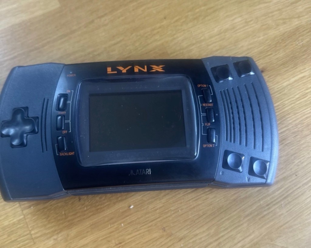
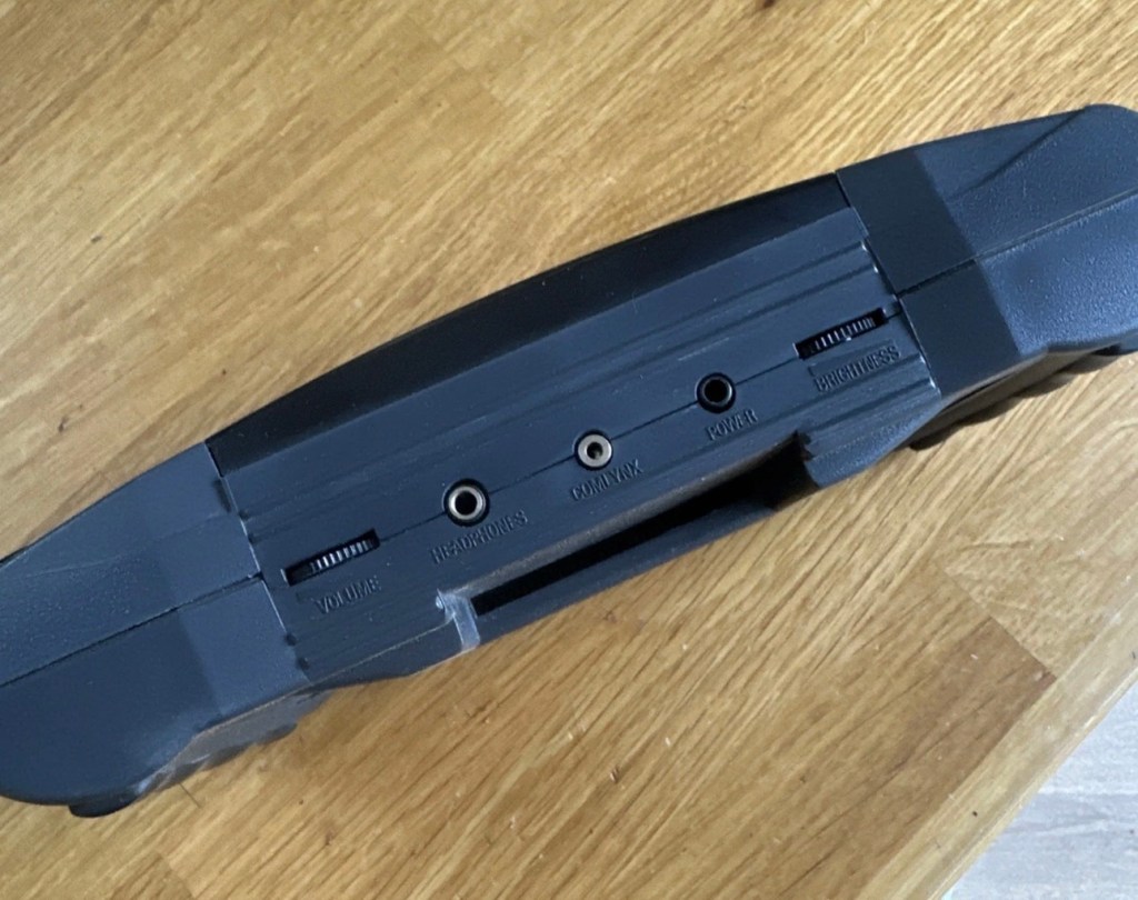
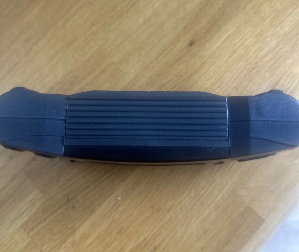

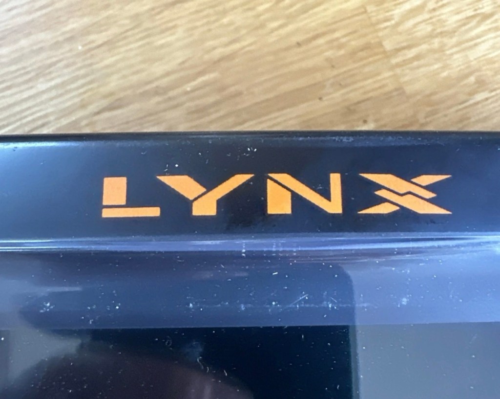
It’s a faulty item, one of many I have been chasing over the last few months, however their resale prices even when faulty, can command some quite hefty prices. I’ve managed to purchase this one at £65:00GBP and that is a price I am content with, as some of the recent ones I have seen went for a higher price even with parts missing or body damage. Cosmetically this one appears to be in a good condition with everything intact. However, the actual fault has not been declared, just that it is faulty and not working. I will have to do a little fault finding to pinpoint the issue, though I suspect initially that a full capacitor change will be the order of the day.
I want this to be part of my personal collection, alongside the Lynx 1 that I also have.
Here’s a little bit of information regarding this unit:
The Atari Lynx II, released in 1991, is the sleeker, redesigned version of Atari’s pioneering 16-bit handheld color console. It addressed original flaws by offering improved battery life, a backlit LCD, and stereo sound, while retaining impressive hardware features like hardware sprite scaling and a unique “lefty” flip mode.
Key Features and Design
The Lynx II packed advanced technology for its time, including several highly unique design choices:
The Display: It features a vibrant 3.5-inch color LCD. Unlike the original, the Lynx II included an option to toggle the backlight off to save battery.
Left-Handed Mode: Because of its symmetrical control layout, the entire system can be flipped 180 degrees. The internal software features a “flip” button to invert the screen, converting it into a truly left-handed console.
Vertical Gameplay: Some games, such as Qix, are designed to be played holding the system vertically like a book, taking advantage of its unique design architecture.
Comlink Play: It supports up to eight players for local multiplayer over “ComLynx” cables.
Hardware & Power Specs
Processor: 16-bit custom CMOS chip (nicknamed “Mikey”) running at 16 MHz.
Graphics: Custom graphics chip (nicknamed “Suzy”) featuring hardware sprite scaling, zooming, and distortion.
Battery Life: Runs on 6 AA batteries, which deliver about 4-5 hours of gameplay with the backlight on. Due to this high power consumption, an AC adapter was a common necessity.
Courtesy t’internet
So, without any further suppositions as to what’s wrong with it, let’s just await its arrival to carry out a full assessment.
Assessment:
I believe that to do a proper test on these units you have to have a game cartridge installed, this is my first issue, I don’t have any cartridges so I have had to purchase the cheapest one I could find for testing purposes. I’ve managed to pick one up for £11:00GBP and to be honest that isn’t too bad. It may well be the worst game they ever produced, who knows? But it will be fine for testing purposes.
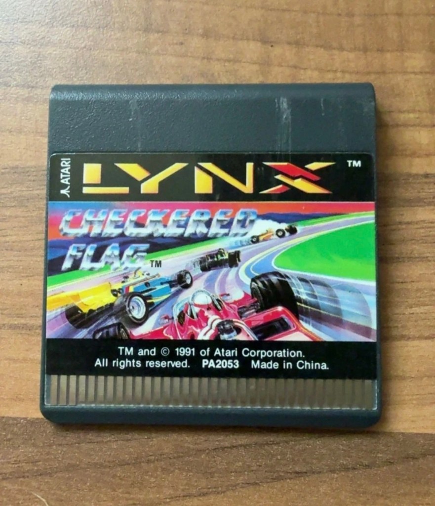
Well, we still wait. Two weeks down the line and only the game cartridge has arrived. Not much I can say about that apart from it looks ok.
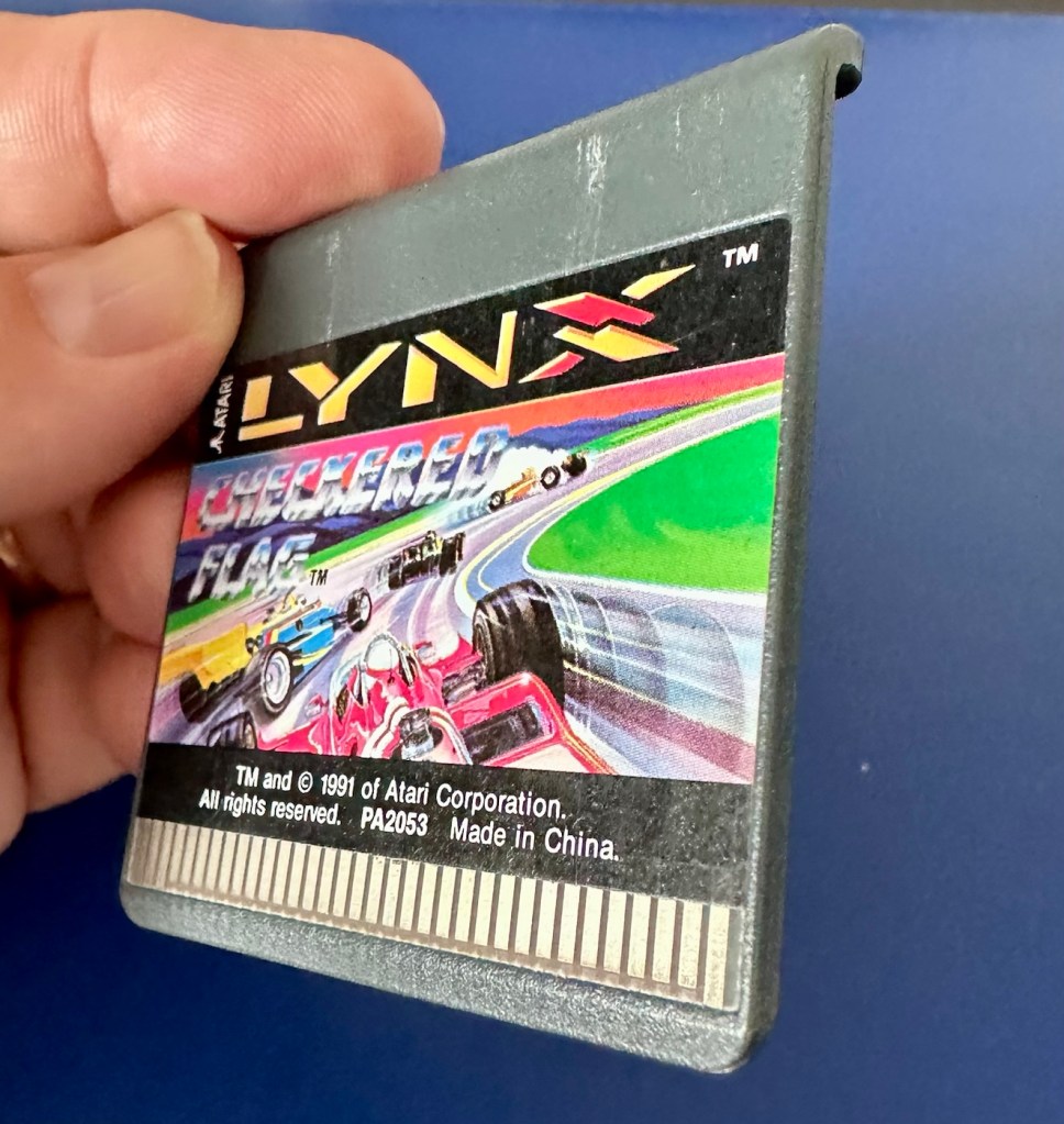
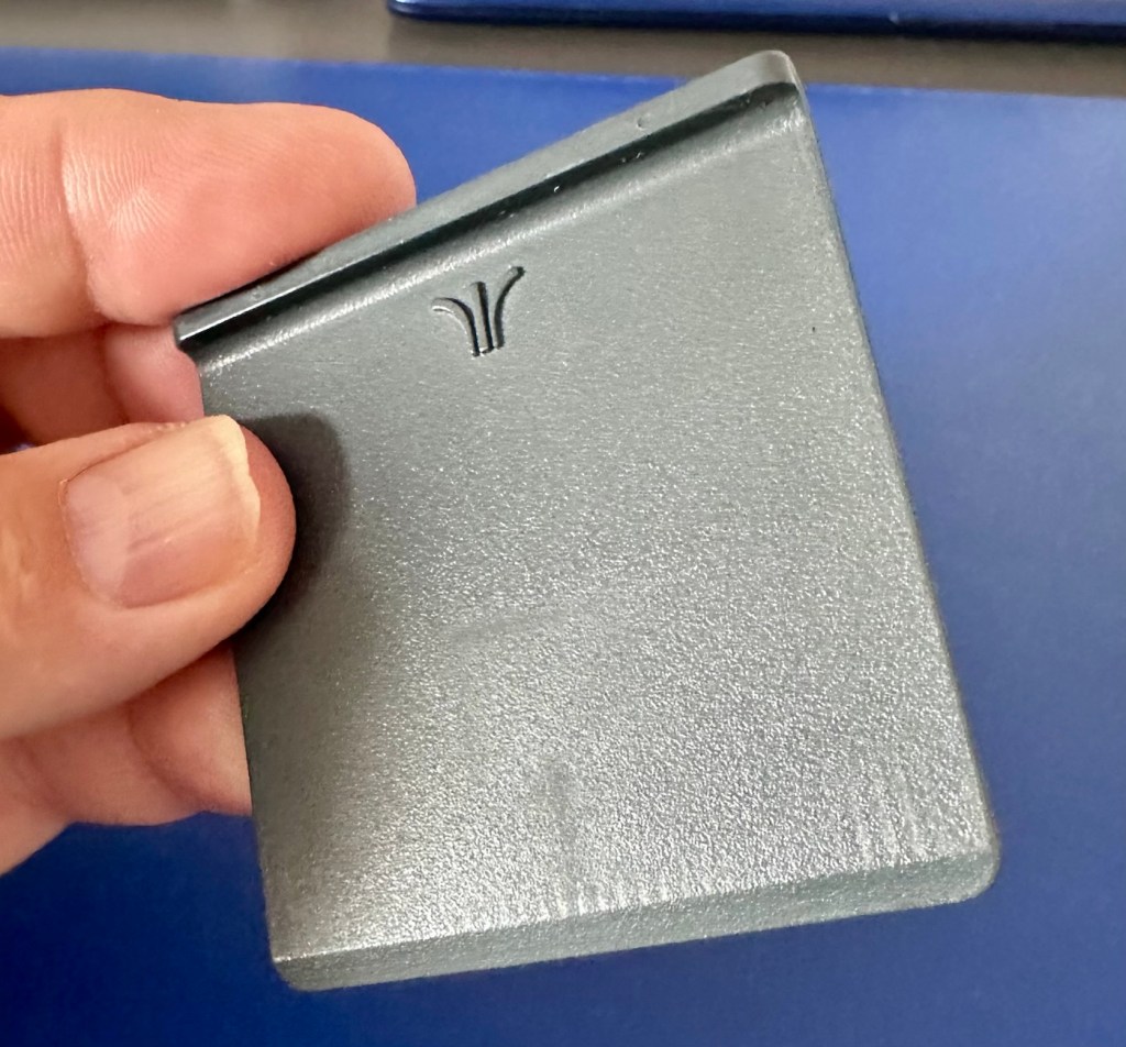
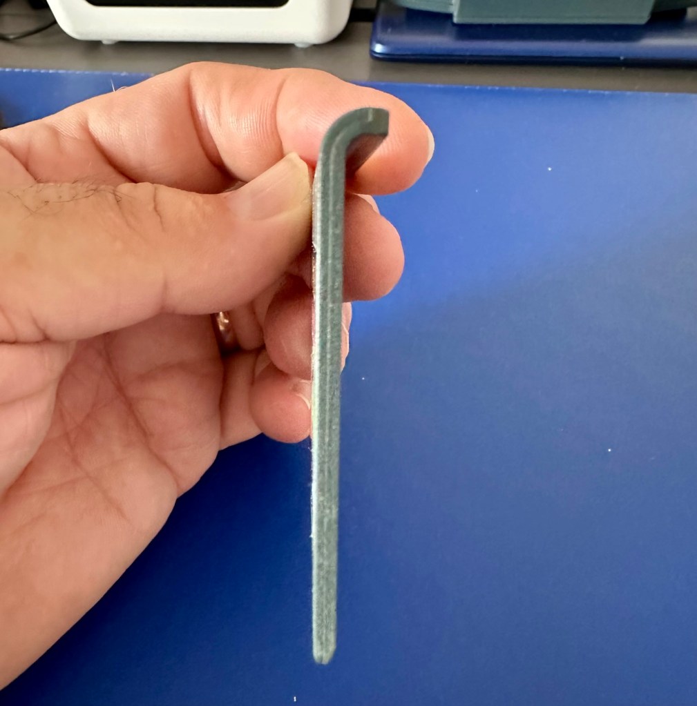
If the game doesn’t function there is not a great deal I can do here. As you can see it’s just a wafer thin plastic plug with no user access available. About the only thing you can do is clean the contacts.
We just need the console to arrive now……
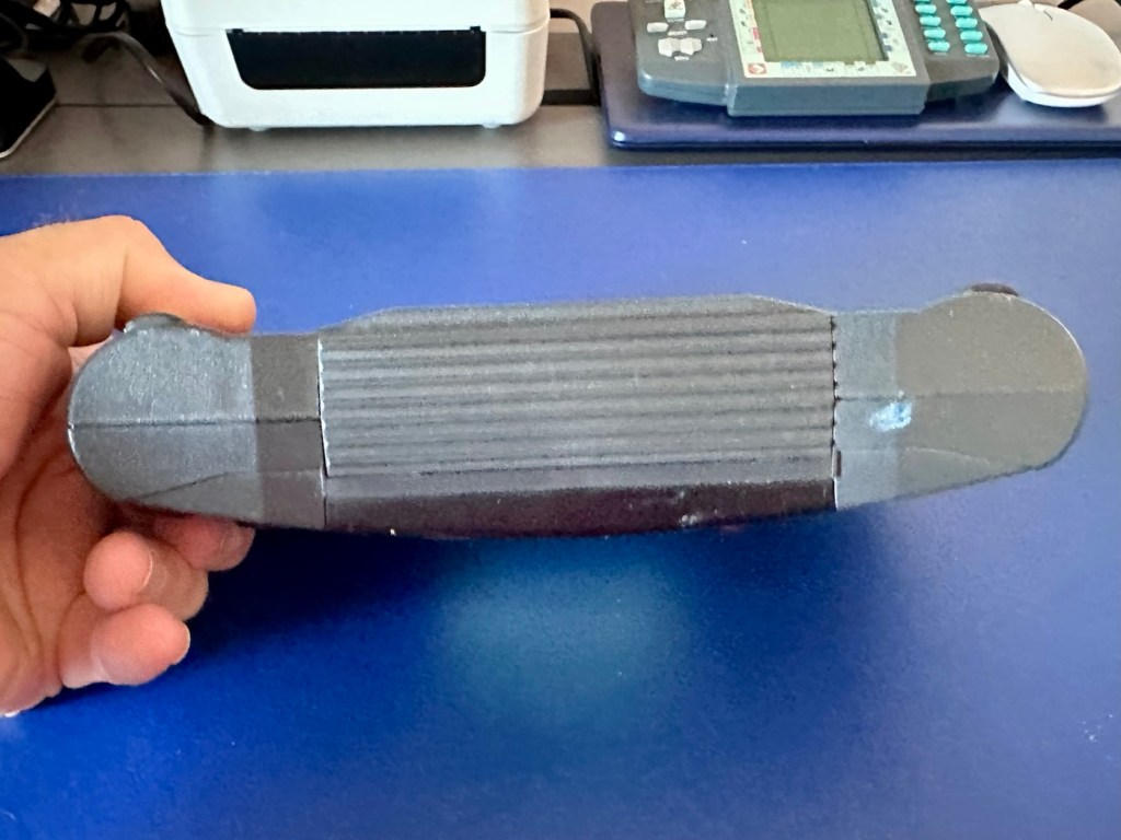
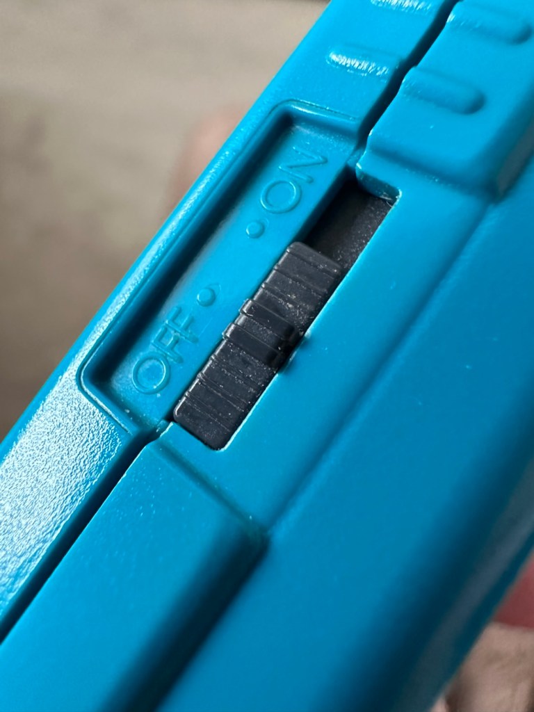
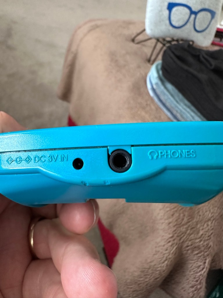
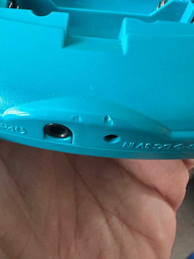
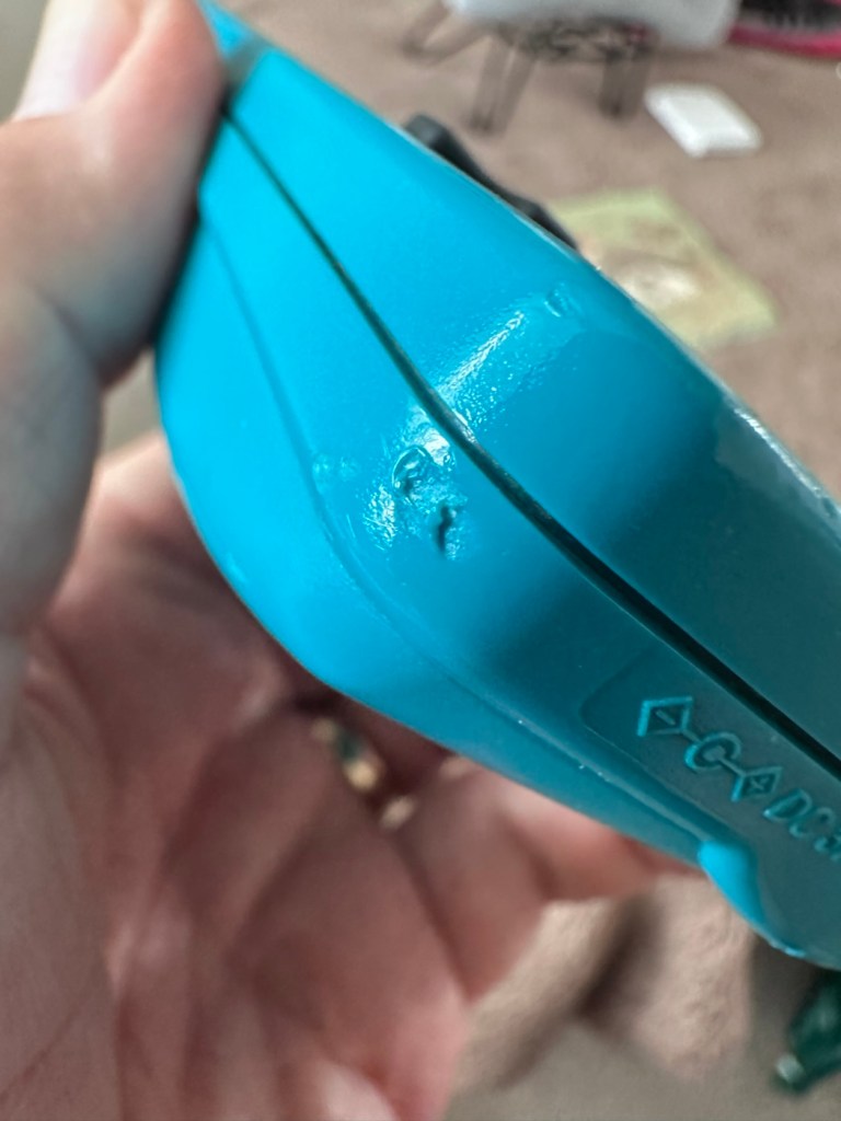
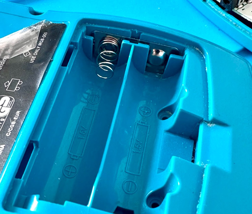
And it’s arrived and to be quite honest it is in a good condition cosmetically, and for an item that’s now 35 years old it has been well looked after. No need to put any batteries in as there are already a fresh set in there, I have checked their voltages and they are fine. 6 x AA batteries turning out around 9 volts, the units requirement.
As I have previously stated, without a game cartridge installed the unit does not turn on. When a game is installed and the unit is turned on, I get an audible short “click” and the back light of the screen comes on, I get nothing else and am unable to get any sound or adjustment on either the volume or screen contrast dials.
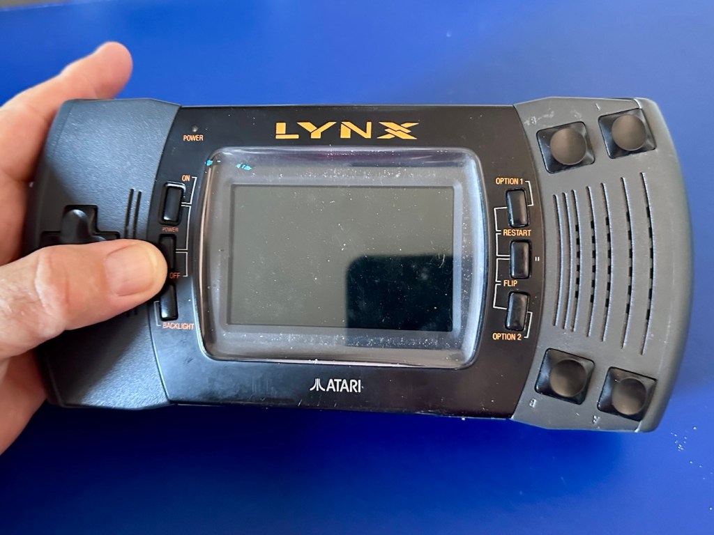
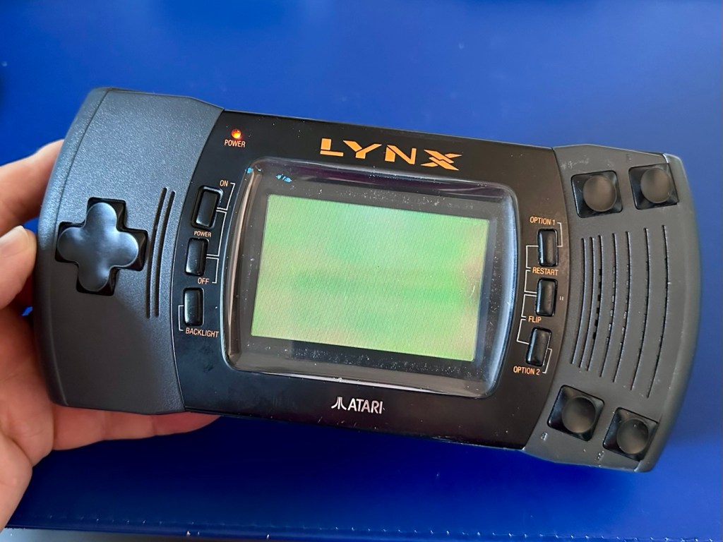
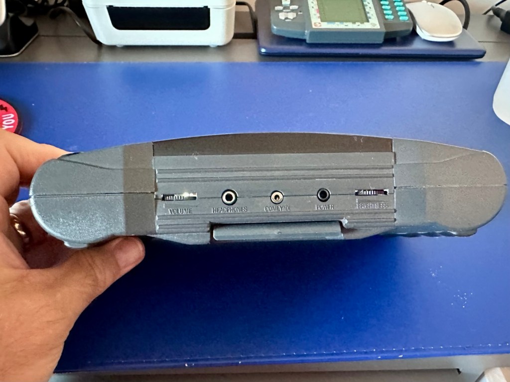
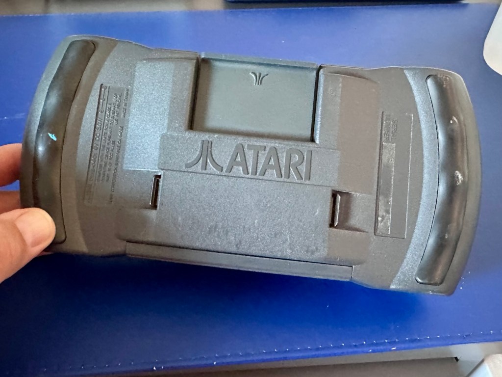
It’s looking very much like either a screen issue, or an issue related to the failed capacitors on the main board. There is one particular capacitor “C41” that controls the main power board that is notorious for failing. I will check this initially to see how it is fairing, if it is ok I will make my way through the board checking other components as well as looking for other points of known failure such as weak solder joints.
Repair:
Firstly, let’s get into the unit, and this requires the removal of five screws in total.
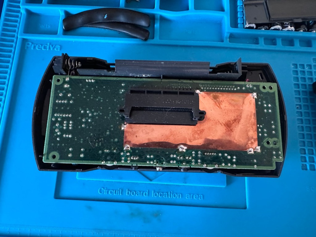
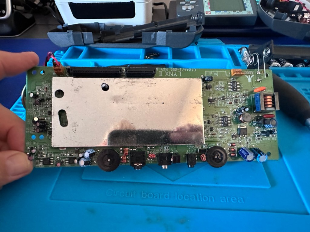
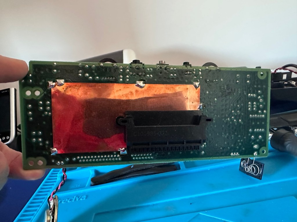
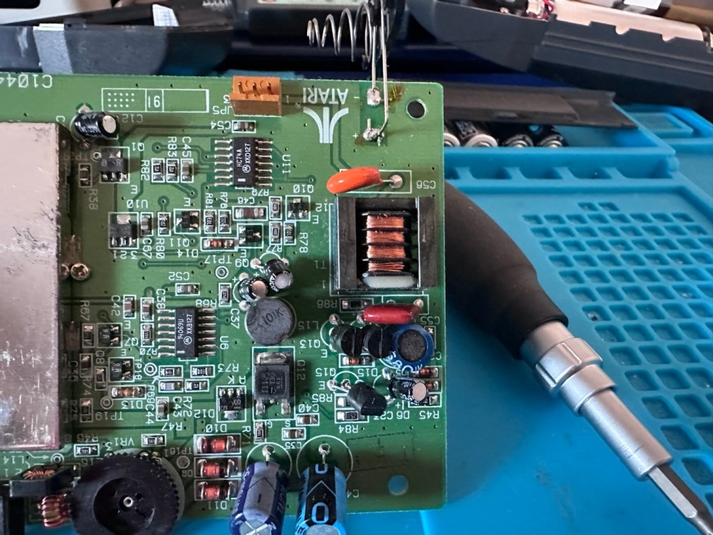
The back should then lift off. Carefully remove the two screen ribbon cables, the power jack and the speaker jack and the whole of the main should just lift out.
A word of warning here. The power side of the board has a number of points that if touched will give you a nasty jolt of many hundreds of volts, a very quick and potent shock and you will certainly know what’s happened. Be very careful handling anything in this area, especially around the capacitors, and always make sure you bleed the power once the power source has been removed. If you are working live in this area, please be very careful. It’s amazing that just 9 volts of injected power can create such high voltages. You have been warned!
I’m going to order a full replacement capacitor kit, for an item of this age it’s probably a wise investment if you want the unit to be around for a good few years yet, even if the caps are not at issue they would probably need doing in the end anyway. The capacitor kit in its entirety (number of caps*) costs £9:80GBP and that’s a really reasonable price to pay to ensure the units usage can continue for many years to come.
The capacitor kit has arrived and there are 24 included. I think there are only 20 to replace (I could be wrong) so I may have a few left over.

I’ve started by removing the most prominent known capacitor that falls and that is C41. It’s a 10v 470uF value and has a tolerance of +\- 20%. So in Theory this capacitor has a value that can fluctuate between 376 and 564 micro farad, and the one on this board is registering 514uF. In theory it is still working, however it’s gradually creeping closer to to the limits of its tolerance.
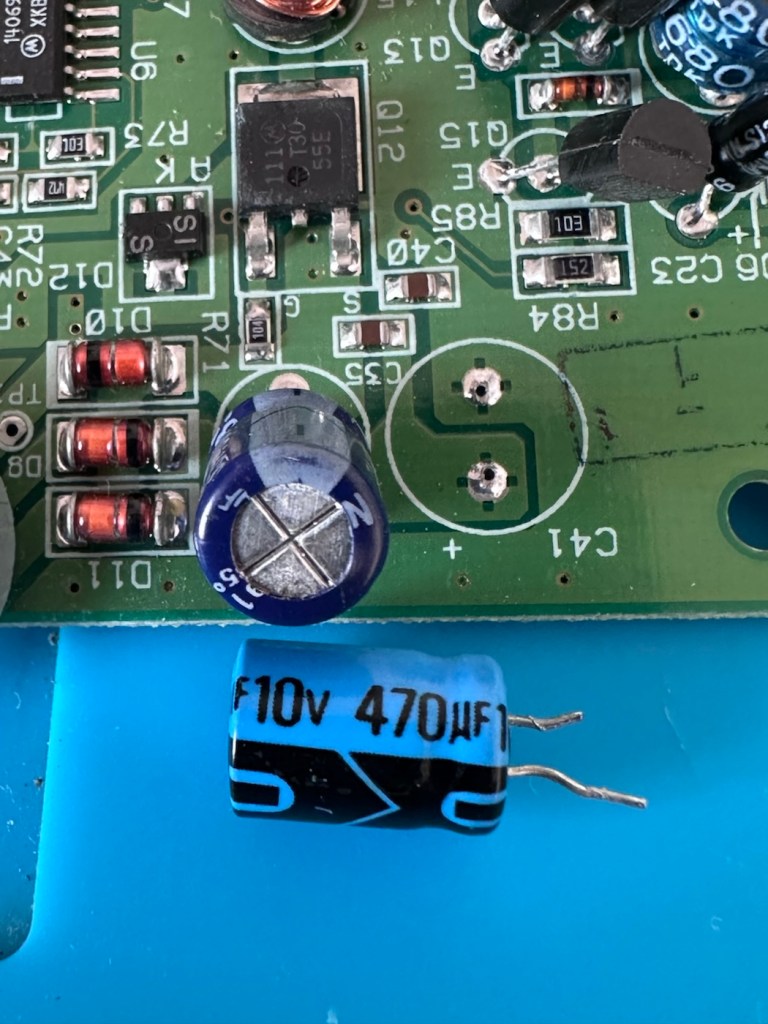
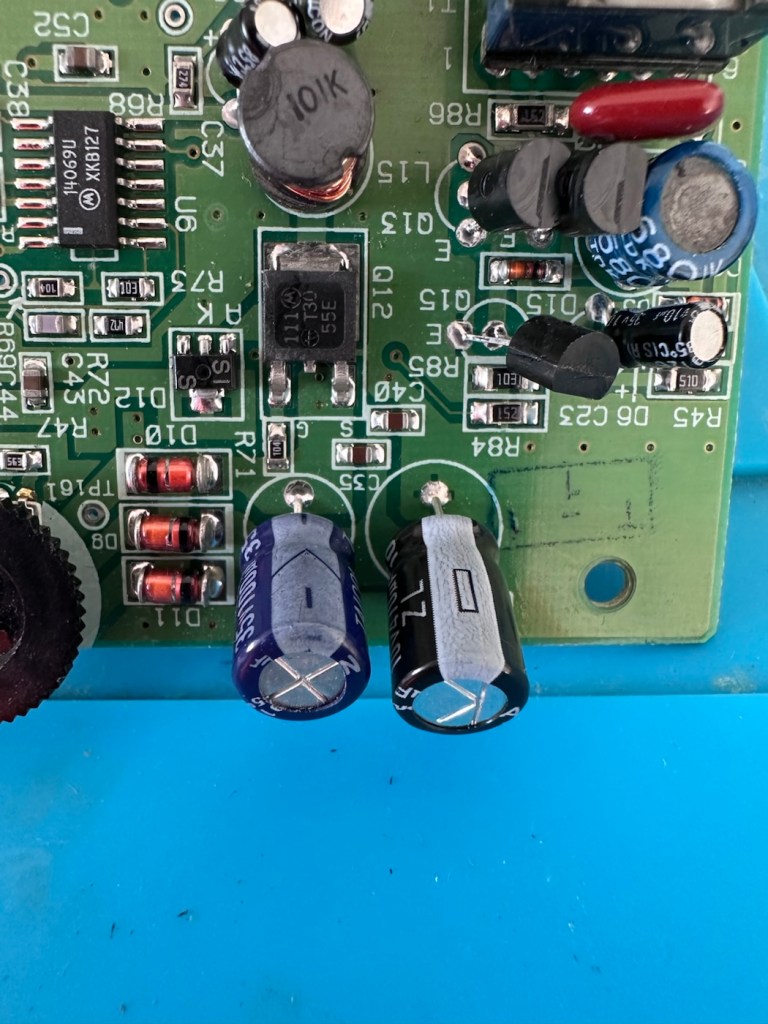
And to be honest, that was pretty much the same result with the other 19 I replaced. All were within their tolerance but at the higher end. The problem here is not capacitor related, however it’s always a wise move to replace them, before they finally go bad and cause other issues.
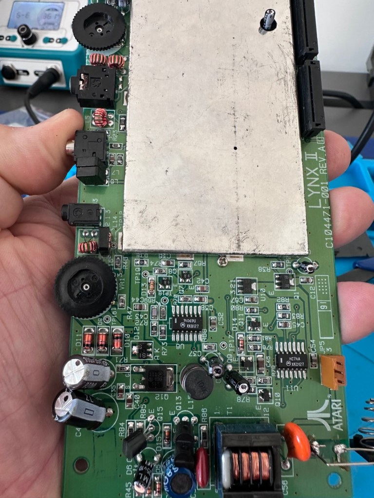
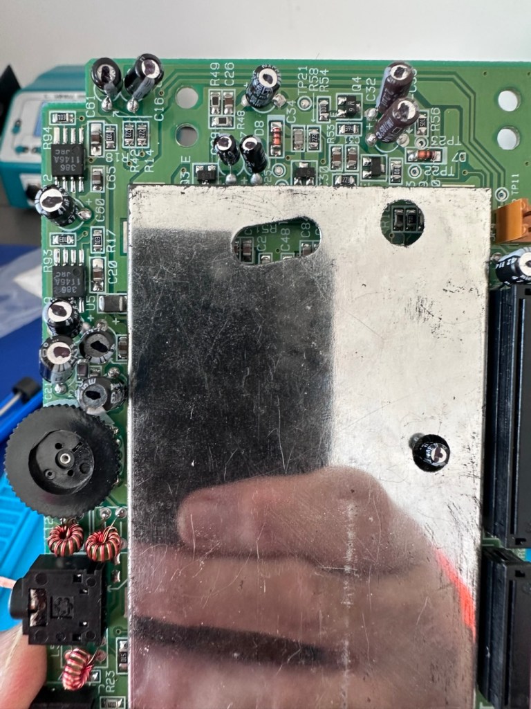
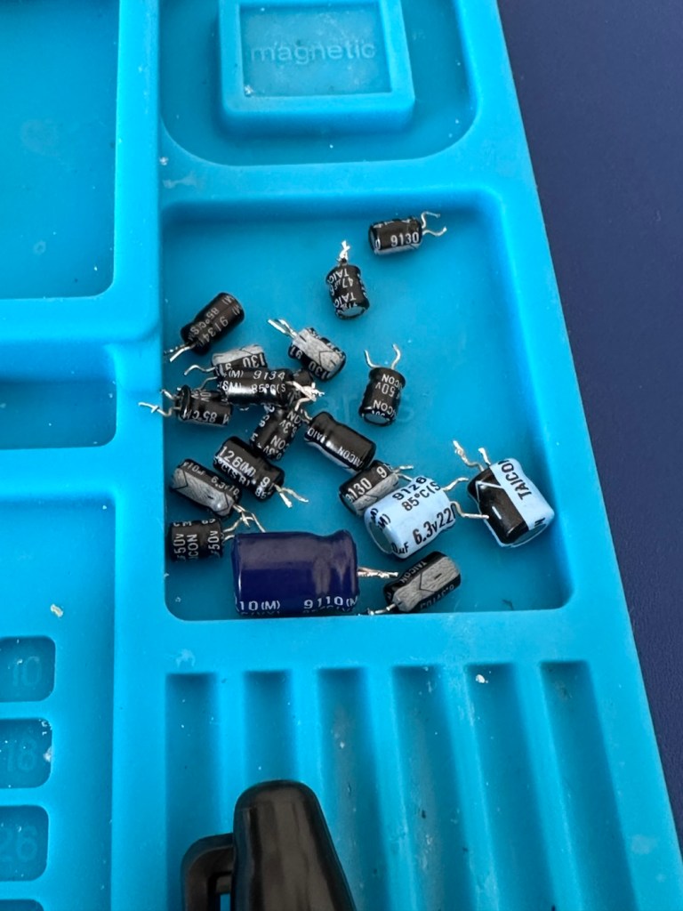
The recap has been successful, however I know it’s not going to make a difference, and putting it back on power confirms this. There is no difference to what I was experiencing when I first tested the unit.

Annoying though this is, it is a job that needed doing and I’m now going to have to focus my attention elsewhere. I’ve checked the polarity of all the capacitors and I’m confident they are installed correctly and in the right positions. There are a few tests and checks to yet carry out, I’ll just have to do a bit of investigating to take this repair further.
These boards and their components such as the main chips and ram were developed to work with a power of 5 volts. However the problem here is that the supply via batteries or via an external power supply is 9 volts. Here lies the issue. On these units the power suppression part of the circuit, those components that filter and lower the voltage from 9v to 5v were known to fail, and when they did they failed quite spectacularly. With no protection built in to stop a surge of power, if some did fail, the full 9v would be supplied to most sensitive components rendering them beyond useless, and non repairable unless you have another donor board. Worst case scenario here is that the main CPUs of which there are two, could both be dead. In which case I may have purchased an expensive paperweight! But hey, let’s not go there just yet as there are a number of things we can do to check.
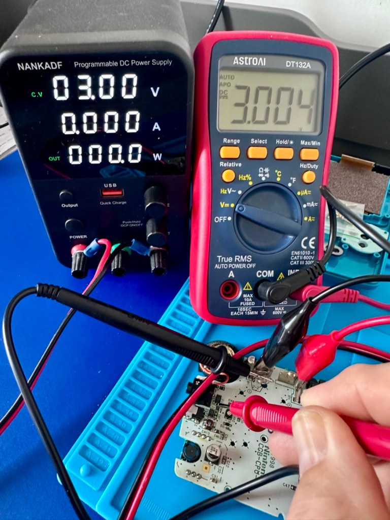
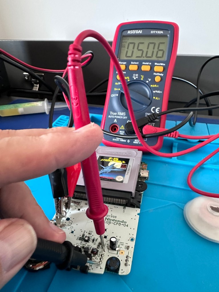
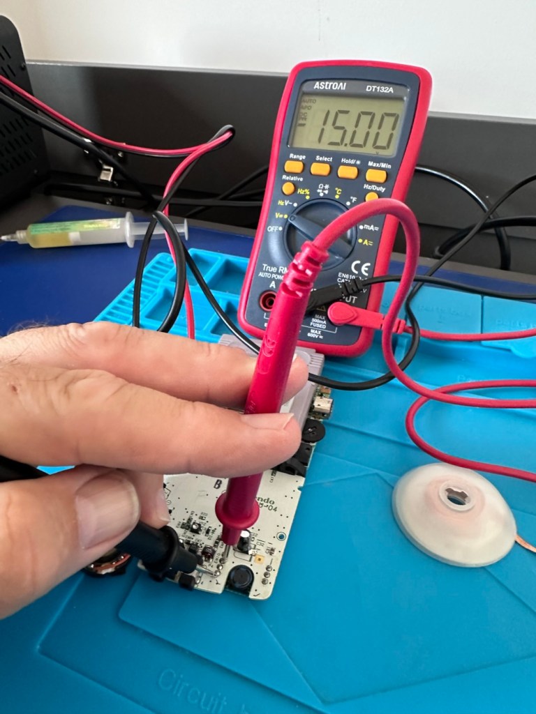
Next thing I have been doing is testing voltages around the board, and they are a little erratic to say the least. It is pointing towards the power board having its usual known issues. I’ve bypassed the power circuit to run a pure 5v through capacitor C14, same outcome here, this disappointed me as I was hopeful the game would kick in, it’s looking more like one of the chips have blown, the further I investigate.
I have done a bit more testing around the power components and I have definitely found an issue with a diode D13, it’s letting power through in both directions and this is not right. I suspect there are more affected components in this area so I’m just going to go ahead and purchase a complete pack of replacement components for those known and prone to fail, on the power circuit. This will cost me £6:79GBP, another cost to add to this project.
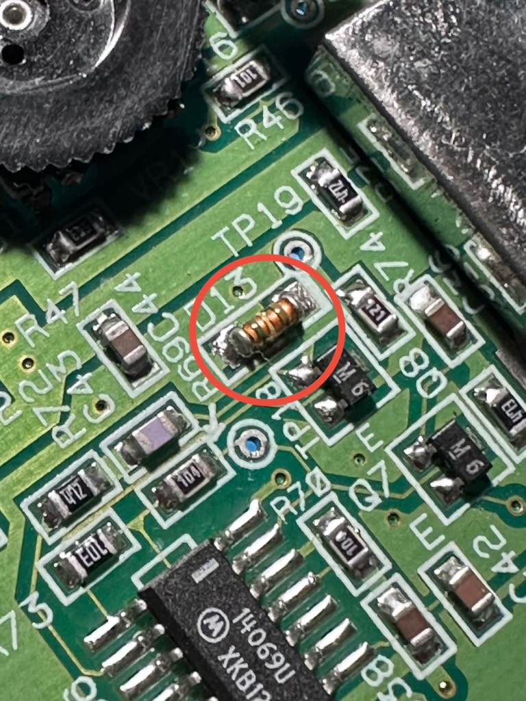
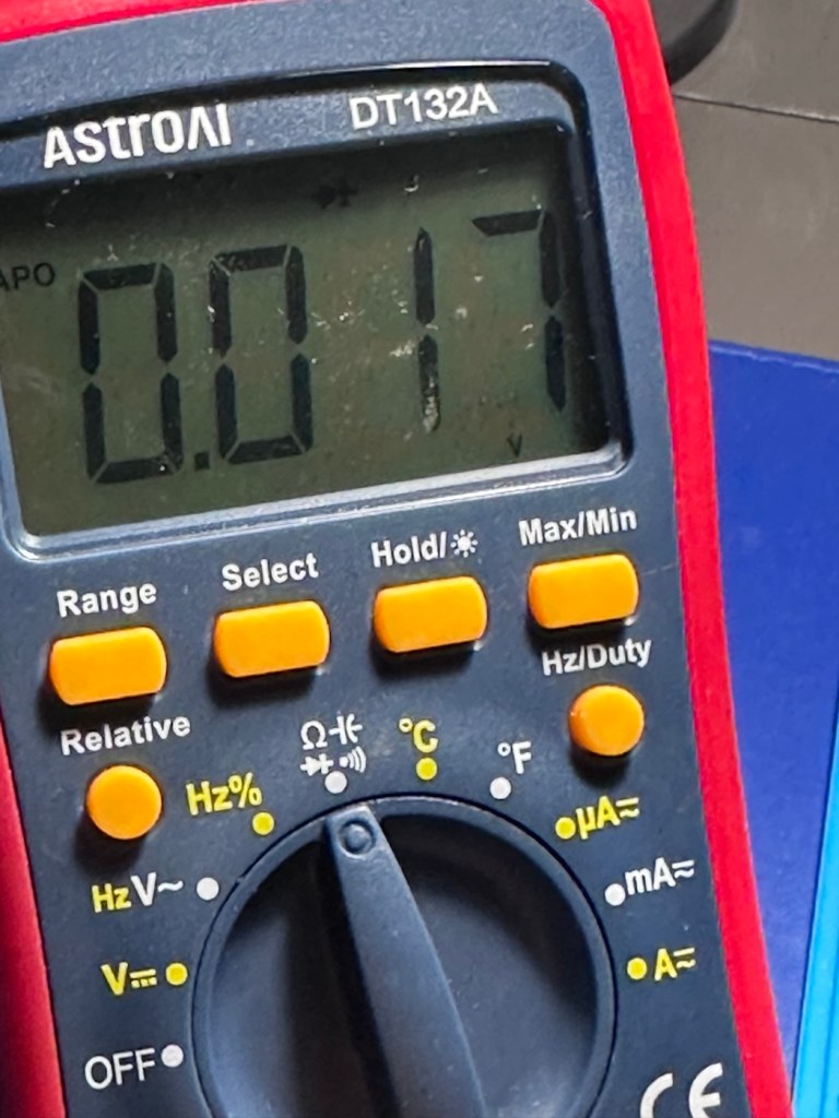
I’m not hopeful though. Current testing results are all pointing to something more terminal. We will persevere for the short term though.
The parts required for the power board refresh have arrived.
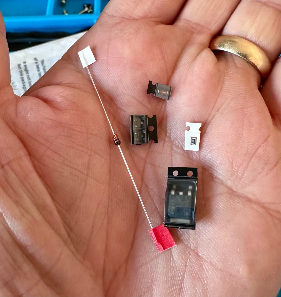
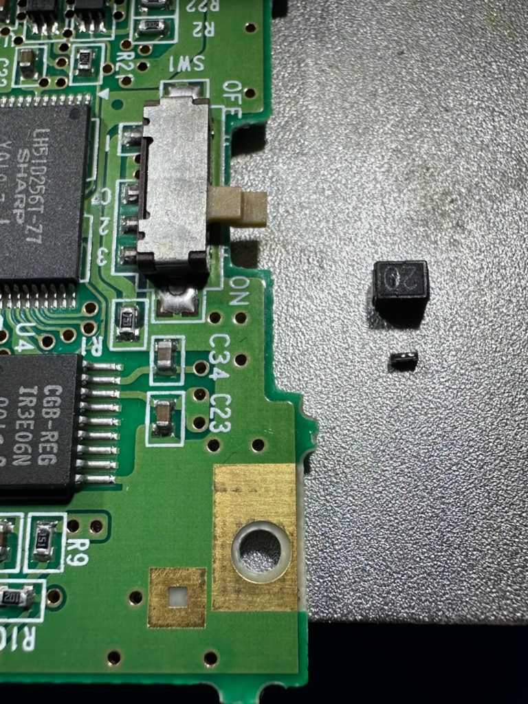
And they are minute in size. Installing these components is going to require a lot of patience and concentration.
The company that sell this power board refresh kit in the UK is ZedLabz.com and this is what their accompanying paperwork states:
Within this kit you will find a replacement Mosfet, two transistors, a resistor and two zenner diodes of different mounting types.
Part locations:
Q11 – Mosfet
Q4 & Q13 – Transistors
ZD1 – Zenner diode (two mounting types included)
R56 – Resistor 30ohm
This parts kit can be used on an Atari Lynx 1 or 2 handheld. One surface mount SMD and one axial through hole zenner diode are included, making it suited to both Atari Lynx 1 & 2, you can choose which type of diode you want to fit.
The kit also includes a resistor which can help with some models to push up the voltage enough to get it stable.
The parts we supply in this kit are from Major distrbutors only ensuring they are genuine.
Console dissasembly and internal soldering required.
ZedLabz.com
No kidding there! It should really say some soldering of components slightly smaller than a grain of rice is required. Let’s stop the whining and just get on with it.
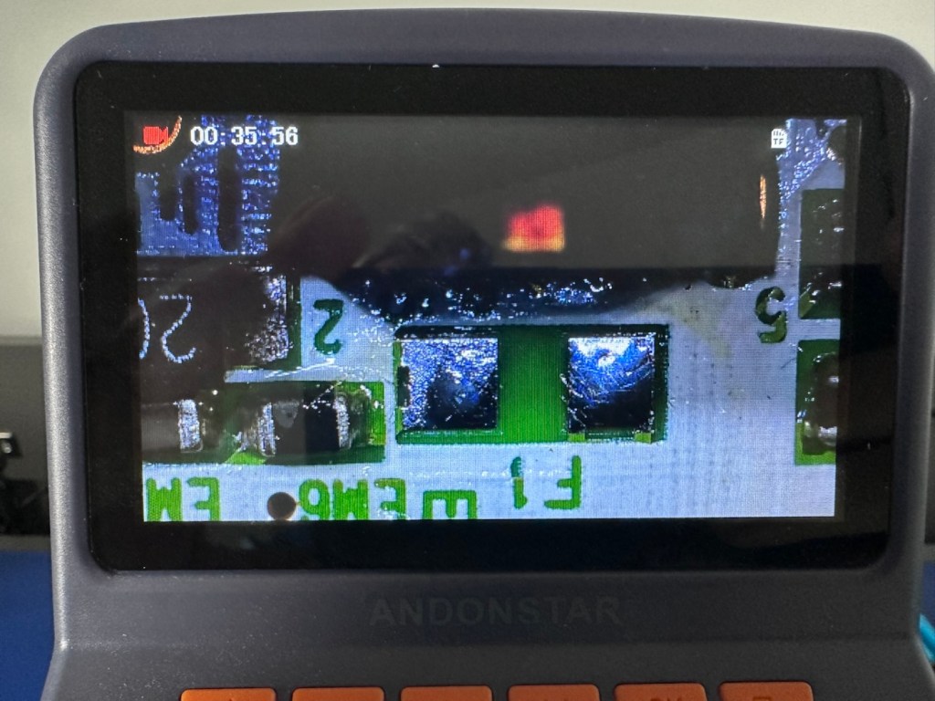
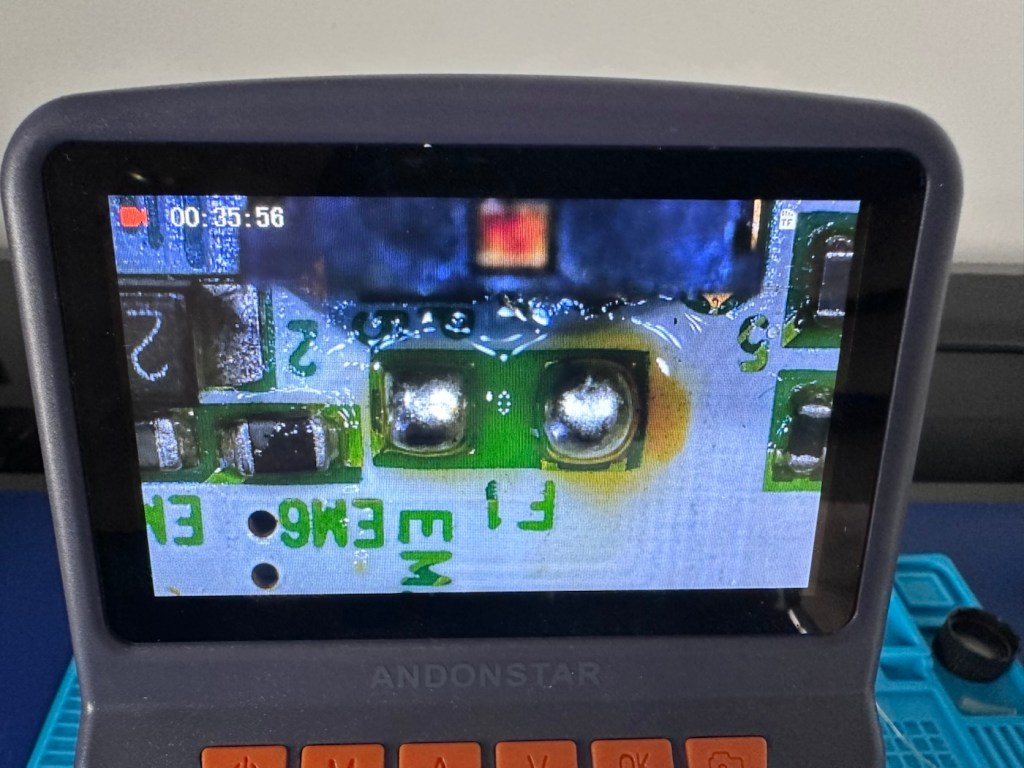
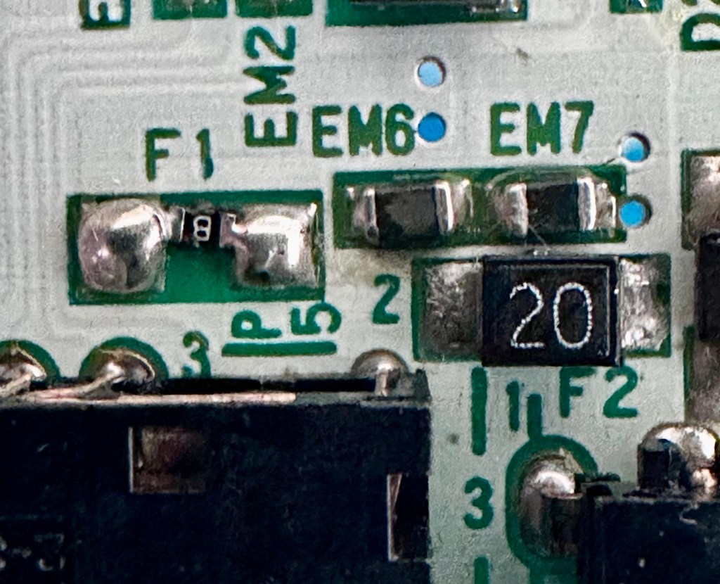
I have replaced all of the five components that needed to be replaced, I’m really quite pleased with the job I have done considering just how tiny these components are, my soldering skills appear to have improved somewhat as a year or so ago I wouldn’t have even attempted such a job. That’s the positive.
But now the negative.
It’s Dead, very dead.
There is still no improvement despite pretty much an entire rebuild of the circuit. I have checked all voltages and they are in the right place showing the correct values. It’s been recapped, the power board has been rebuilt, all solder joints have been checked and ribbon cable connections have all been reflowed.
Result:
My conclusion that the previous owner was well aware of the issues, they probably contributed to the problem and the unit has been sold on as “spares and repair only”. I have failed to pay attention to the old Latin saying “Caveat Emptor” or buyer beware.
The situation is this. A new LCD screen can be purchased to drag the unit into the 21st century, but there is no point when we have no sound and vision being produced. The problem here is that the 9v power supply has already been able to get to the delicate parts of the circuitry where only 5v should be in attendance. I am 99.9% certain that the ram chips as well as the two logic chips “Mikey & Suzy” have long departed. And there lies the problem. The two logic chips are as rare as hens teeth and are pretty much only available when transplanted from a donor unit. The unit is basically dead, it’s just a paperweight.
I will put the unit into storage until a later date, when I have done a lot more research and who knows I may even find a suitable donor board to transplant those two logic chips.
For now the project is on hold. I don’t like writing of failures as many hours of work over many weeks has been dedicated to this project. You can’t win them all though, and some you just have to step away from a project to get a fresh aspect on it. Having this log of activity is fantastic for me though as it will now become the reference for where I go next.
It’s a learning curve, that’s for sure.
When I come back to the project I will obviously link to this post.
Thanks for passing by. It’s always very much appreciated.
 Foxes Den
You must be logged in to post a comment.