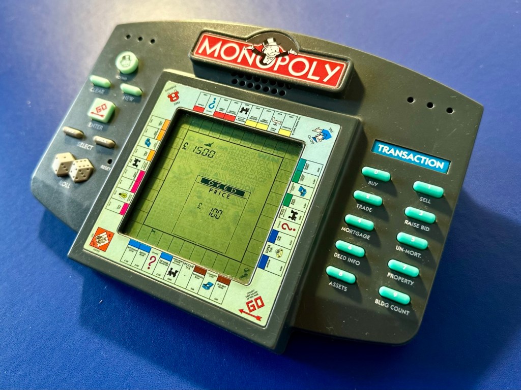
A dead Monopoly electronic handheld game from 1999. Can we resurrect rich Uncle Moneybags?
What the listing stated:
The Vintage Monopoly Electronic Handheld Game from Hasbro (1999) is a classic electronic game that allows players to enjoy the iconic Monopoly game on the go. With its handheld design, this game is suitable for players aged 4 years and above, making it a fun and engaging activity for children and adults alike. Although untested, this nostalgic piece of gaming history is sure to bring hours of entertainment to anyone who enjoys the challenge of a good game of Monopoly.
EBay.
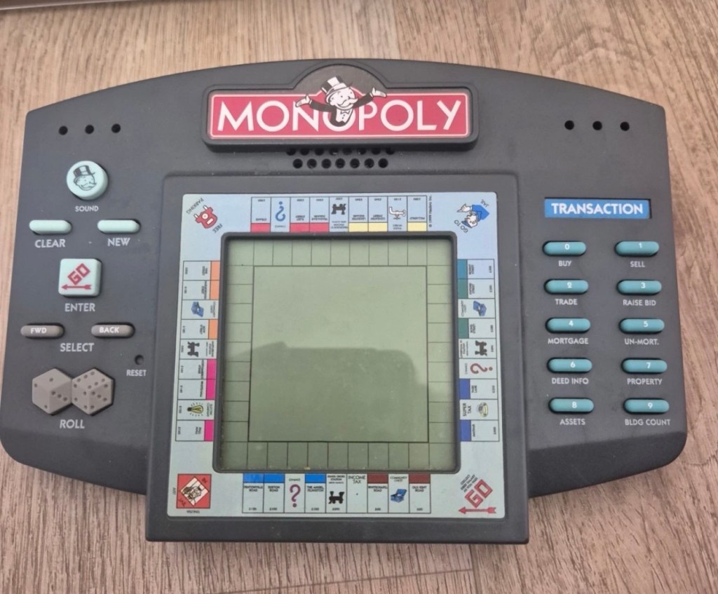
The item I have purchased
The good old EBay get out of jail free card (How appropriate 😂) of untested. This item takes three AA type batteries, just what does it take to pop three battery in and turn on the unit. Why am I so sceptical about this item? I just have a feeling that it’s going to be riddled with issues and I bet one of them involves battery acid.
But, miracles do some times occur, so let’s just await its arrival so I can carry out a full assessment, in the meantime here is a little bit about this game.
The 1999 Hasbro Monopoly Handheld game is a classic electronic version of the board game designed for solo or multi-player action. It features computer-controlled opponents, a virtual LCD board, and an interactive narrator (Rich Uncle Pennybags) who guides you through buying, trading, and auctioning properties.
Gameplay Features
The 1999 handheld faithfully recreated the full experience of the classic board game in a portable format. Key highlights include:
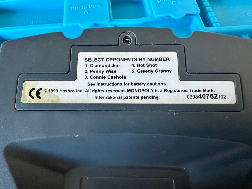
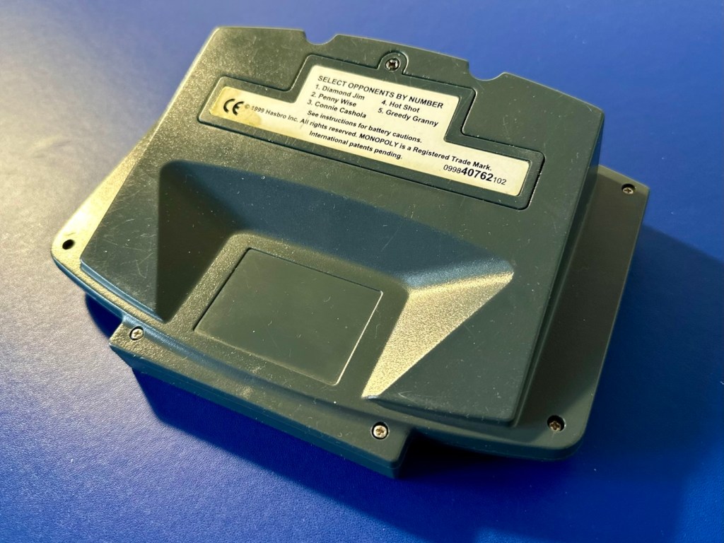
Computer Opponents: Play against up to 3 to 5 distinct, computer-controlled characters (like Diamond Jim or Greedy Granny), all of which operate at different skill levels.
Full Board Mechanics: You can buy, sell, mortgage, trade, and even auction off properties.
Audio & Visuals: Features a custom LCD display, physical buttons for menu inputs, and fun real-sound effects.
Power Requirements: The unit typically requires 3 AA batteries to operate.
T’internet
Assessment:
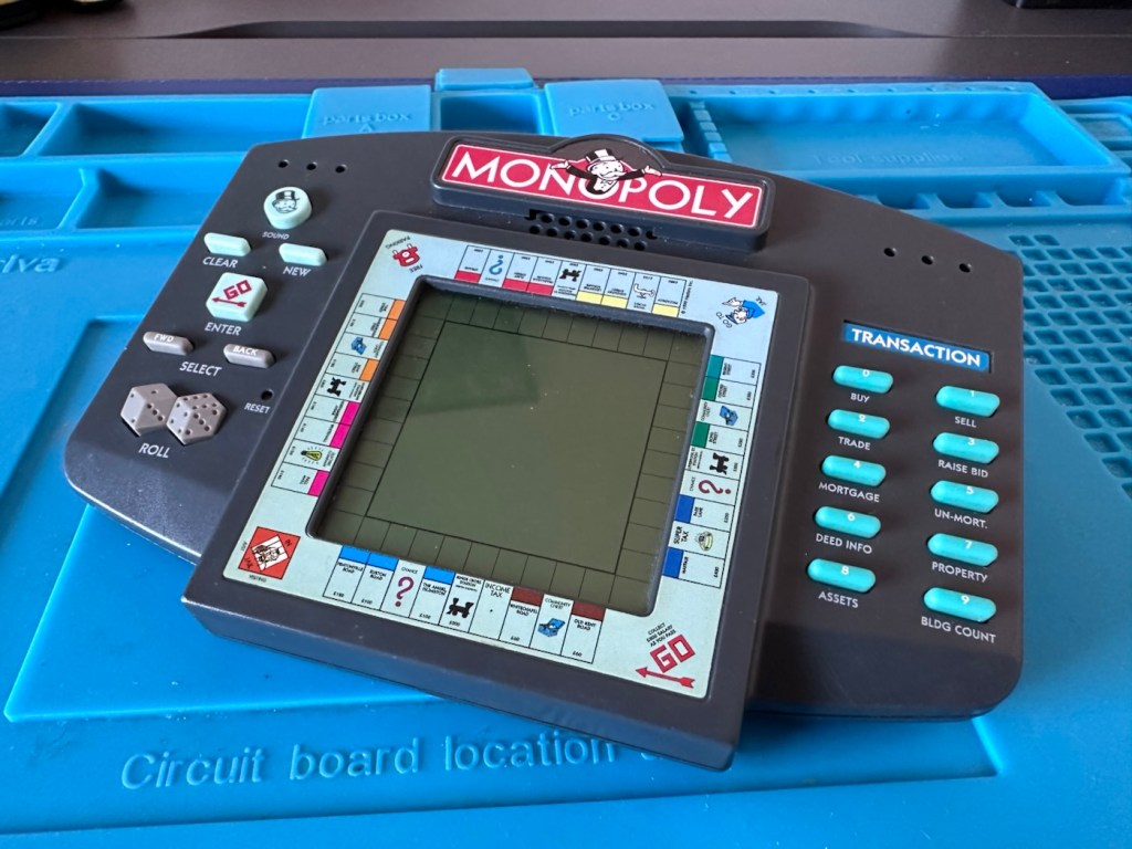
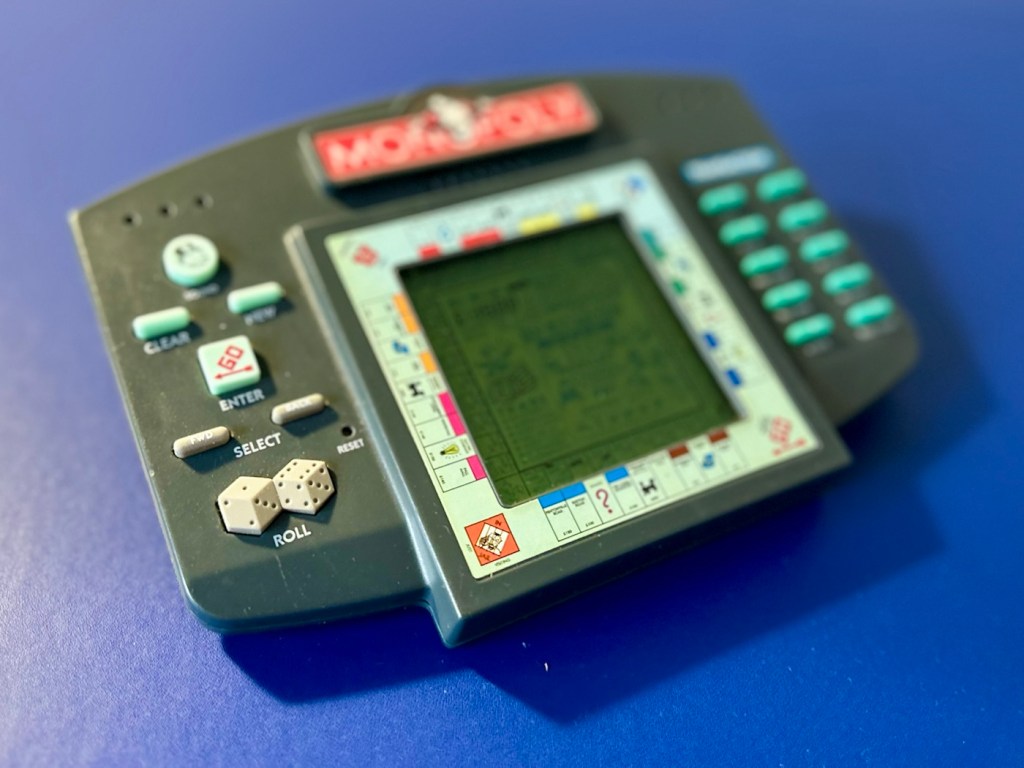
Well, my suspicions in this case are correct. It has arrived and for a unit that is now 27 years old I must admit that cosmetically it is in a good looking condition, with all labels intact, minimal marking on the screen, and all buttons appear to be clicking. All body screws are present and do not appear to have been tampered with at anytime.
Clean, tidyAll labels present
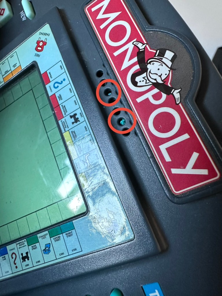
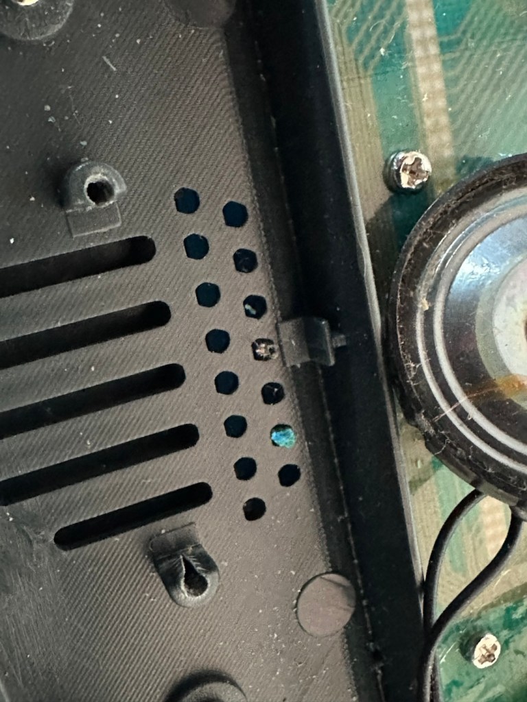
But hold on, what’s that I can see through the speaker grill on the front?
Battery contaminant viewed through the speaker grill.
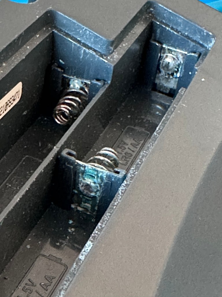
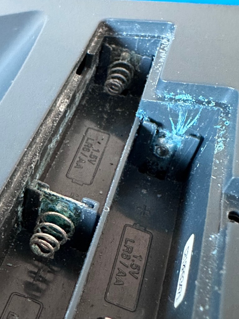
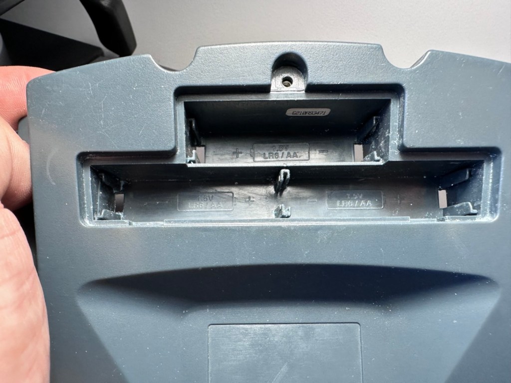
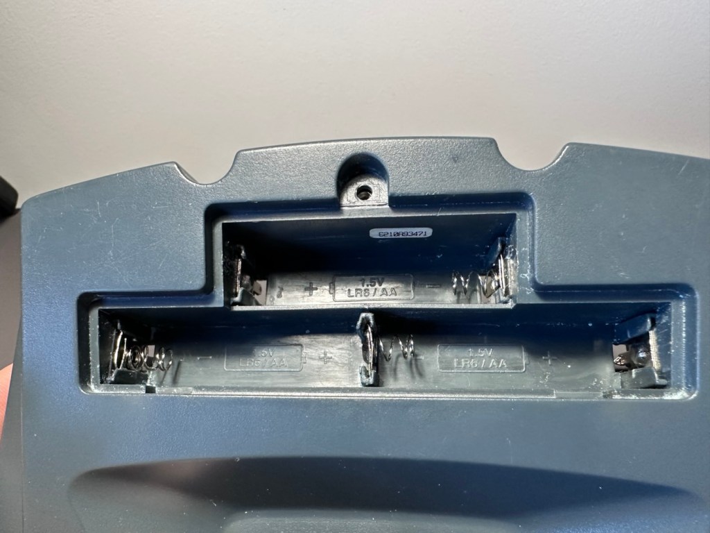
I open the battery company and as I previously thought there are signs of battery contamination.
Battery contamination
Bugger. Ok I’ll put three batteries in but I’m pretty sure I know the outcome. Yep, it doesn’t power on. The unit is dead.
An untested unit. It’s taken me 30 seconds to test and confirm the issue. Wouldn’t have hurt to be honest and to have done the same would it?
I paid £7:90GBP for this unit, it was probably the least expensive of all those available at the time, I guess I can’t complain really, I just detest people’s deliberate dishonesty. Ok, whinge over let’s open up the unit to delve a little deeper.
I open the case and can breath a slight sigh of relief. Yes there are obvious signs of battery contamination, but not as bad as previously thought. As I had seen signs of contamination in the external speaker grill, I’d thought the insides were rotten. In fact the contamination in the speaker grill was only a few grains of contamination that had broken away from the battery compartment.
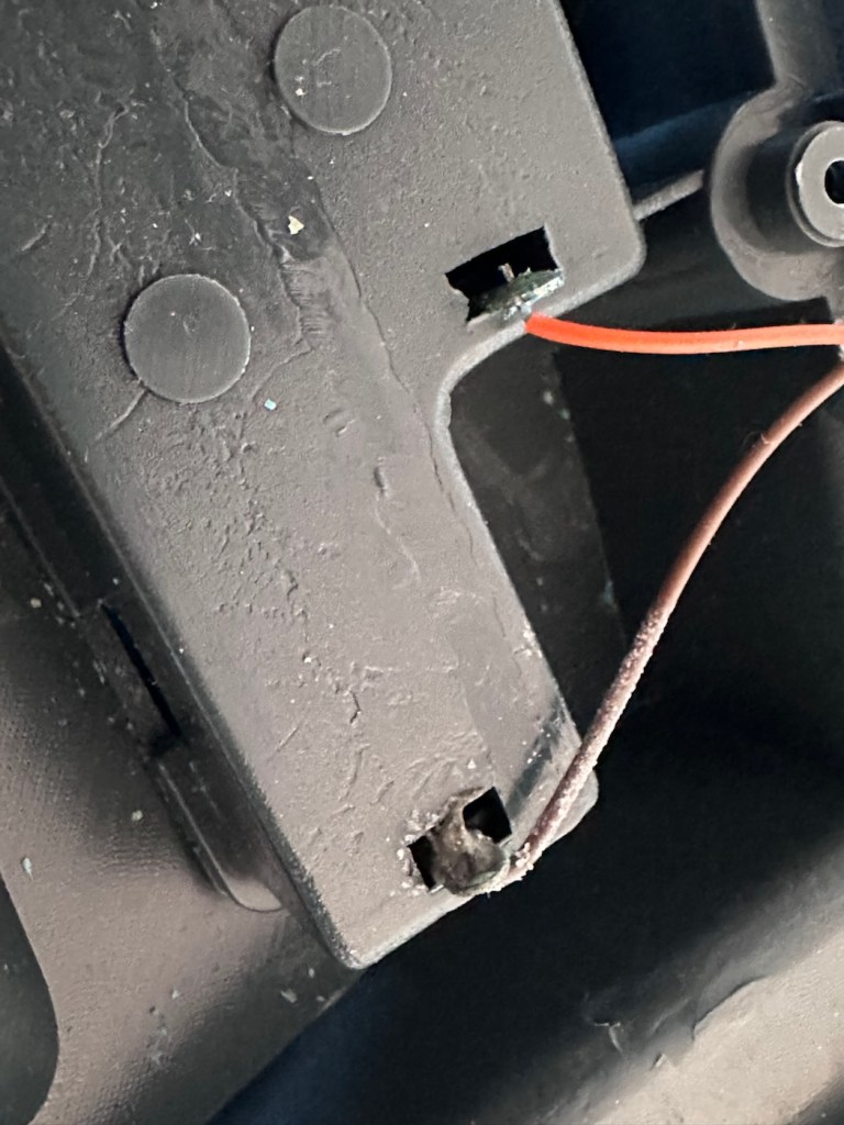
A rogue piece of contamination Wires rotted near the connector Jumper cable brokenHow it looked upon opening
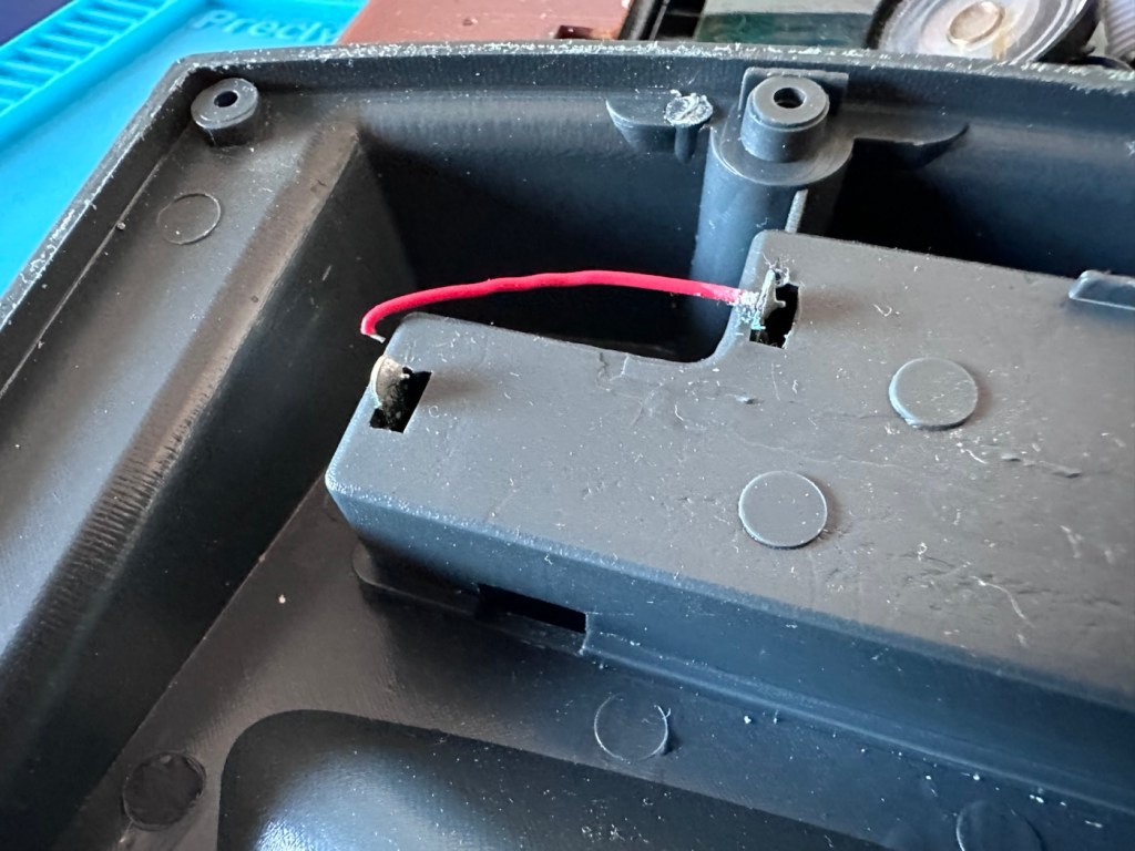
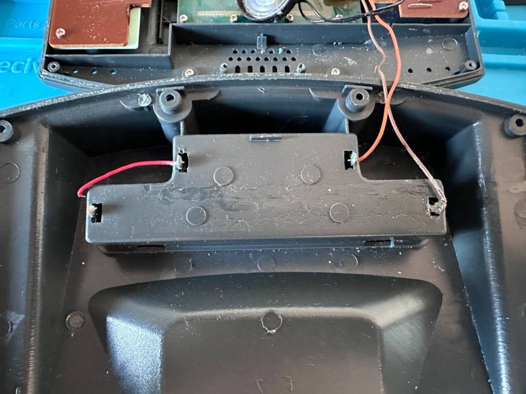
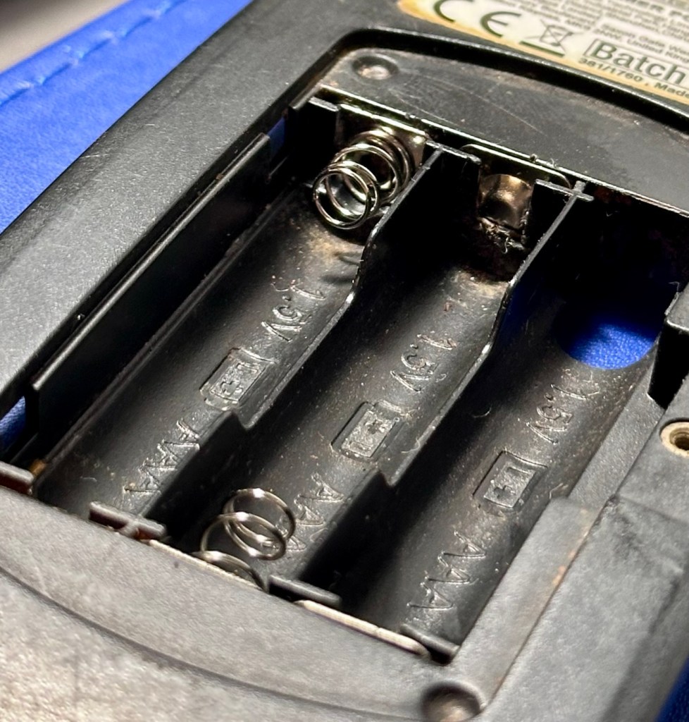
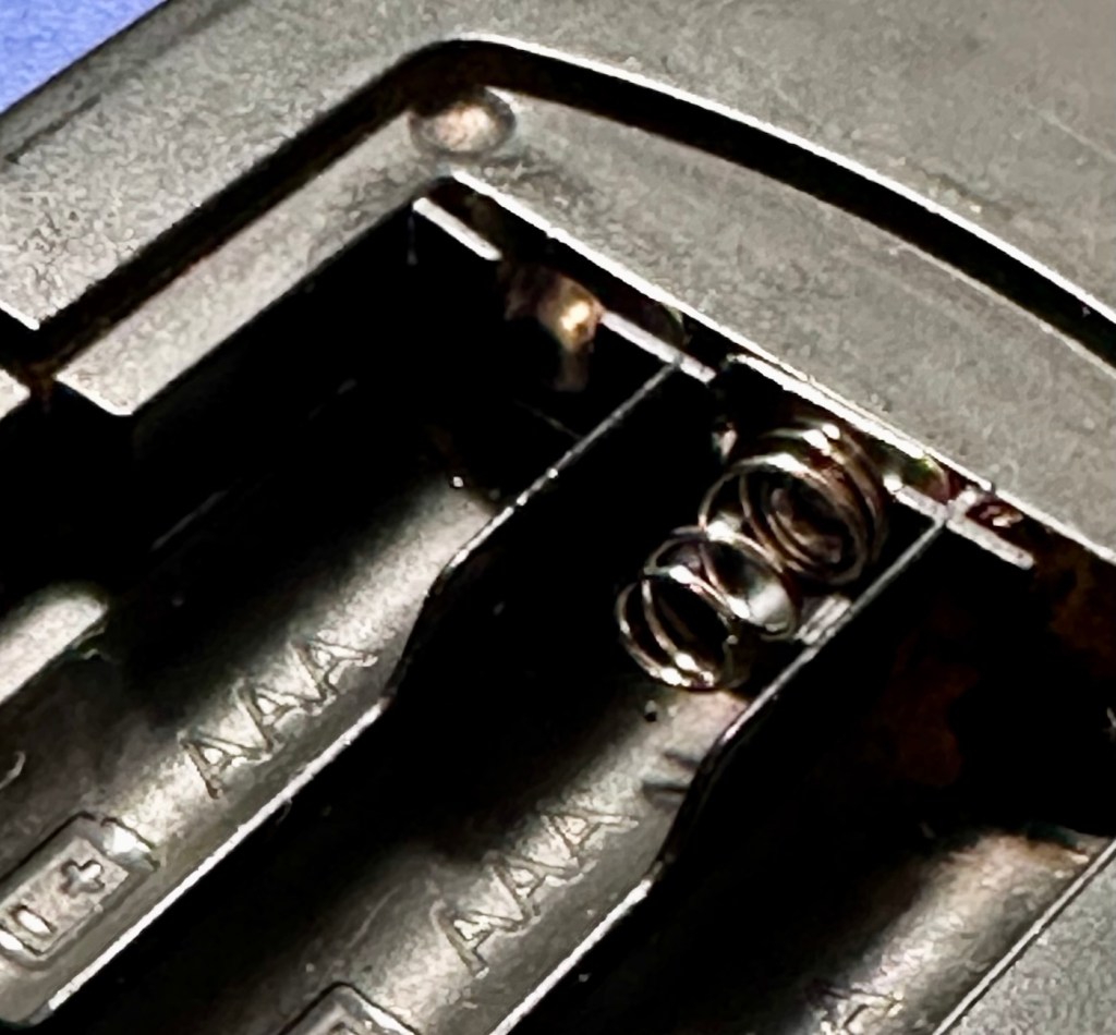
The wires near to the worst points of contamination in the battery compartment were pretty much rotted and covered in old battery acid. One jumper that would complete the continuity of the battery/power flow had rotted off and one of the very thin speaker cables was also broken.
Repair:
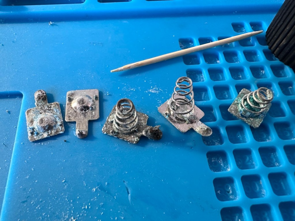
I’ve given the mainboard a good clean with IPA and set about removing all the battery connectors from the battery box.
Old connections outA thorough clean of the areaNew connections in
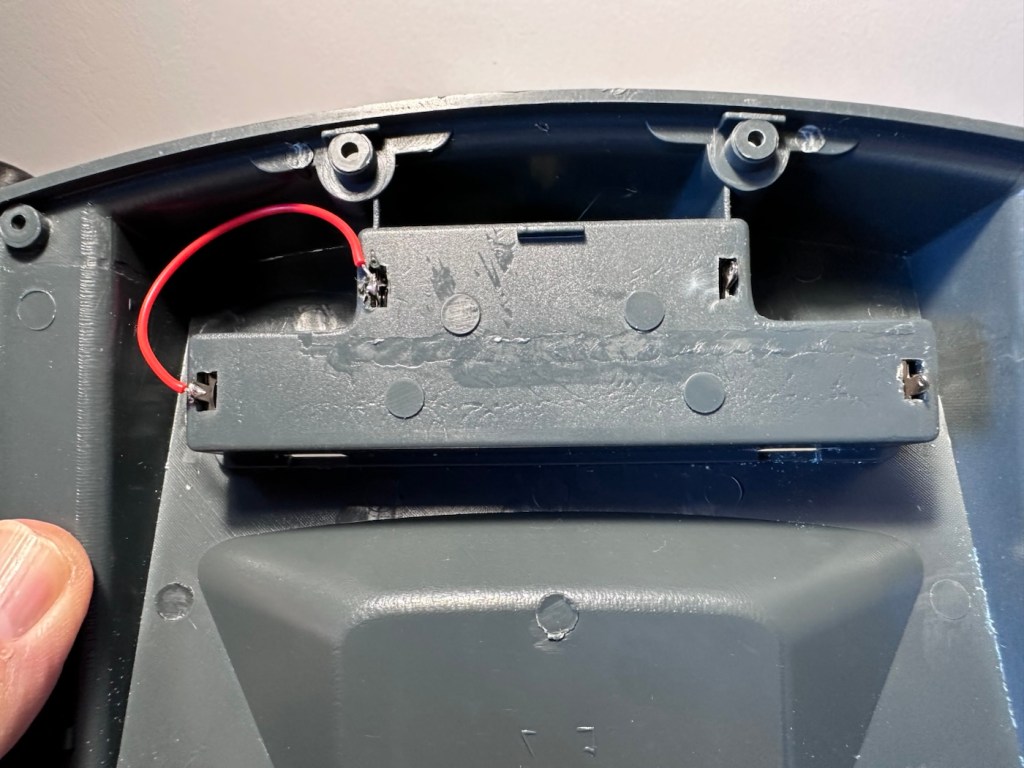
I’ve reattached the jumper cable with some fresh wire, I’ve trimmed the rotted wires down to some good unaffected wire and reattached these to the new battery connectors. The speaker wires are freshly soldered back into place.
New jumper Hello rich uncle moneybags
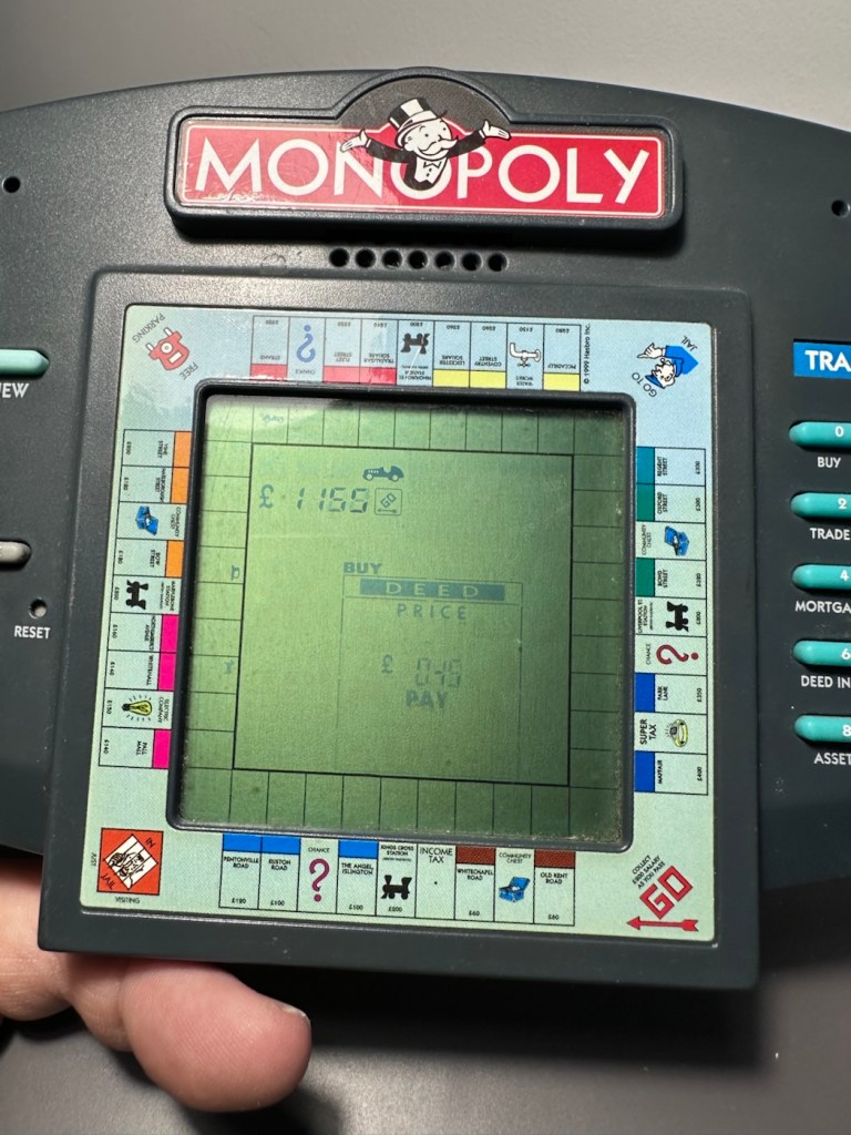
With everything now connected up I put three batteries in to place and can instantly hear the computers electronic voice welcoming me to Monopoly, Rich Uncle Moneybags lives again.
Time to reassemble the unit.
So the issue was here was the result of battery contamination. Four battery contacts, and one wire, were all that were additionally required along with a lot of cleaning and some re soldering to secure some weak connections. It’s now a complete working unit.
Result:
As usual, this would have been a prime target for the tip as it’s just one of those disposable units we have created as the wonderful guardians of this little planet we reside upon. It’s taken probably about 30 minutes of time to repair (and about the same to clean internally) to bring this unit back to life. A good polish externally and it’s now ready to be put back into use.
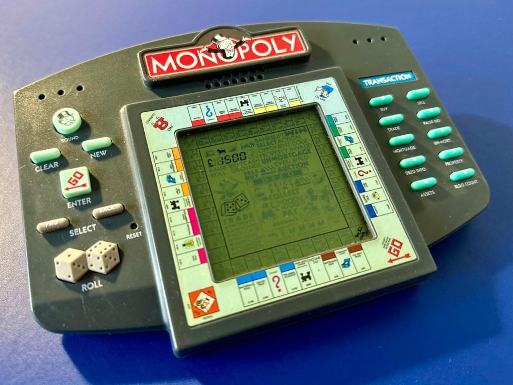
All cleaned and looking good
And my chief tester for these type of items is my wife who absolutely adores the game of Monopoly.
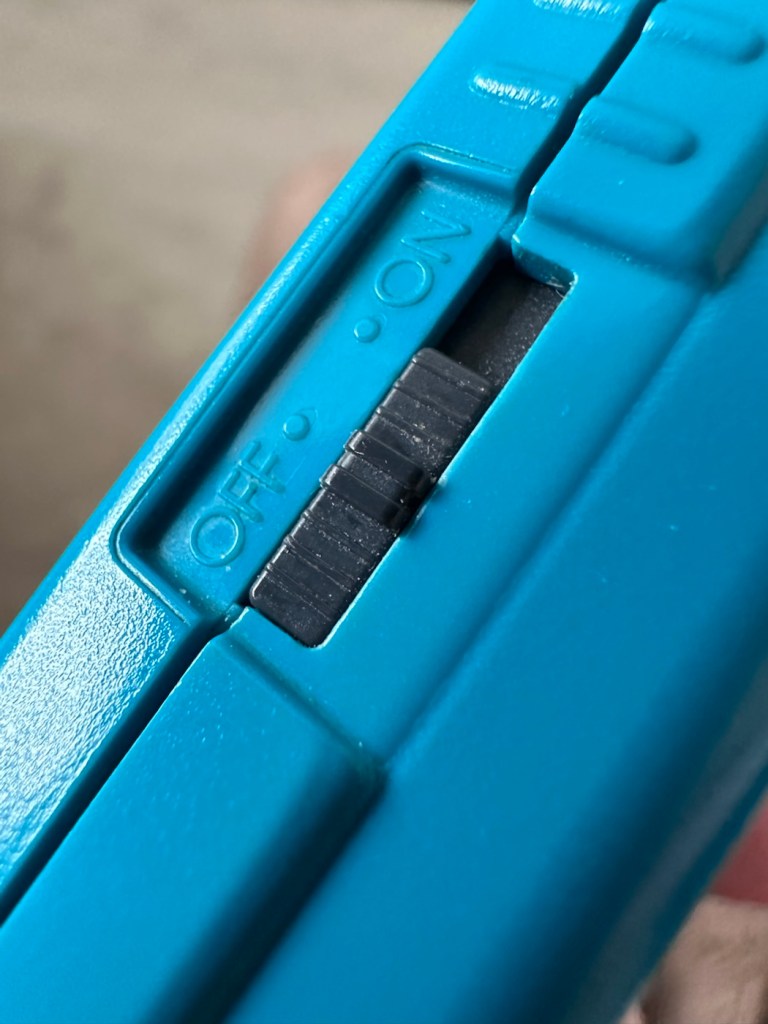
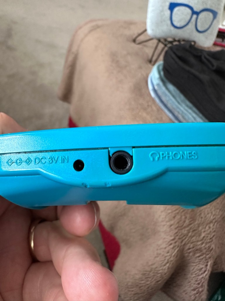
The only real issue with these units is that they never came with an on/off switch. You had to put the batteries in and then remove them when you were finished, this is very strange. However when you read up on line you can see that many people have made modifications to put volume controls (even though there is a three press button version built in) and on/off switches on the unit. I will probably put a switch in myself when I come across a suitable one to use.
In the meantime we now have a working unit, the wife gives it her nod of approval and that’s good for me.
A simple repair, very little outlay and only a little time was all that was required to save another item from landfill. Wouldn’t it be good if we could all take the time to repair rather than dispose.
Thanks for passing by, as always it’s always very much appreciated.
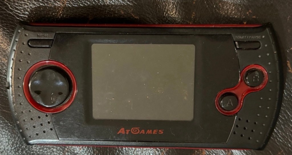
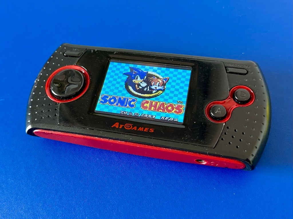
From 2008 this is an AT Games, Sega Megadrive portable games unit. It’s an emulator console that has seen better days. It needs a lot of attention. Let’s see what we can do.
What the listing stated:
I can’t get the device to power on. This is possibly just due to corrosion (and one snapped spring) in the battery compartment. Someone more adept at fixing things may be able to bring it back to life but unfortunately I can’t so listing it as spare/repairs/faulty.
EBay
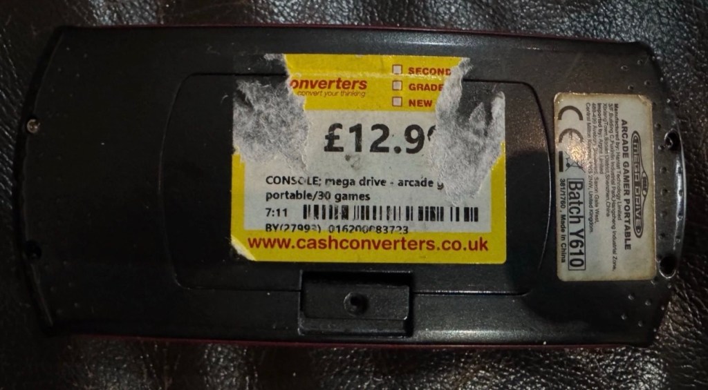
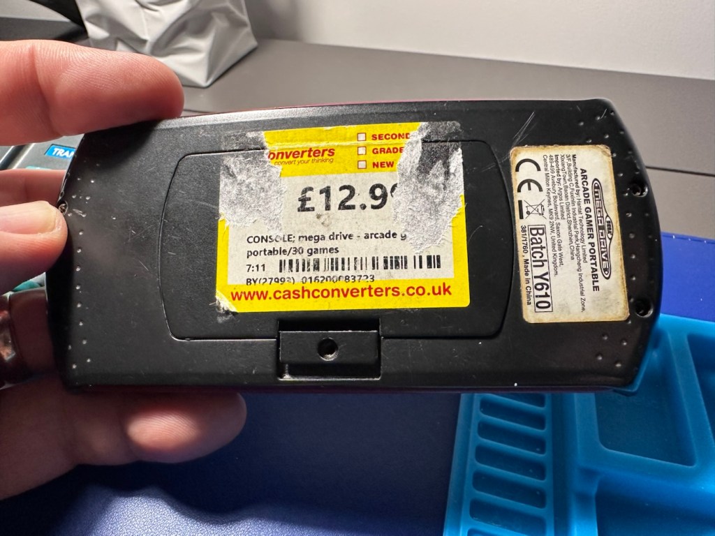
I sure as heck wasn’t going to pay the old price advertised when the previous owner obtained this from Cash converters.
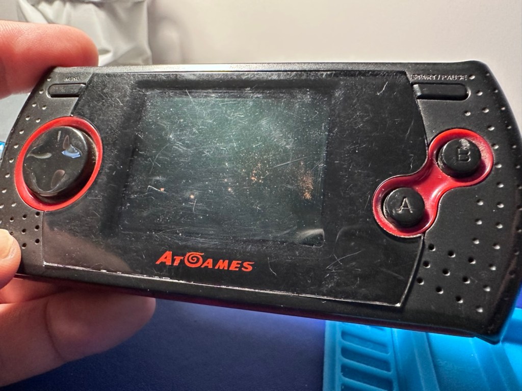
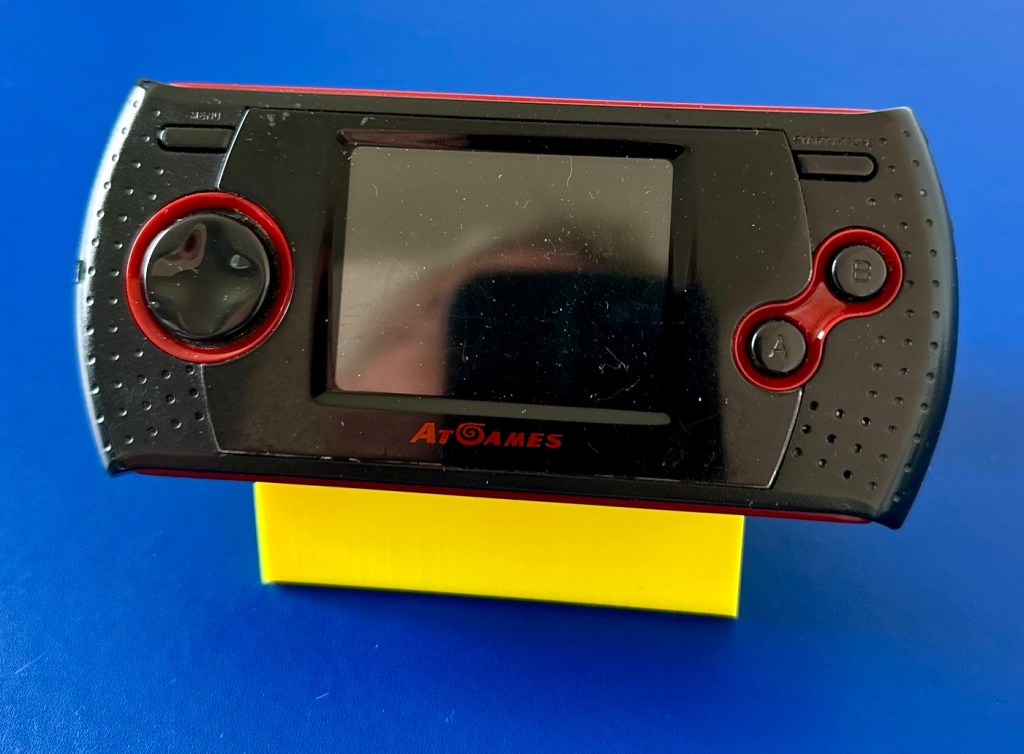
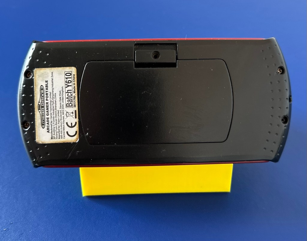
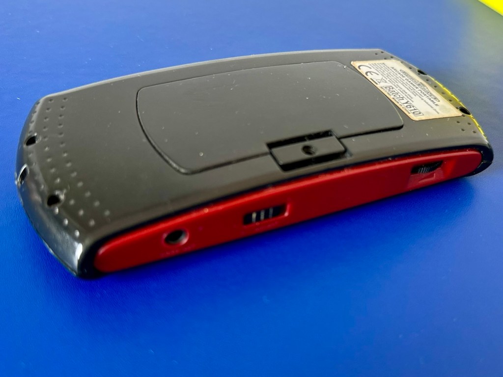
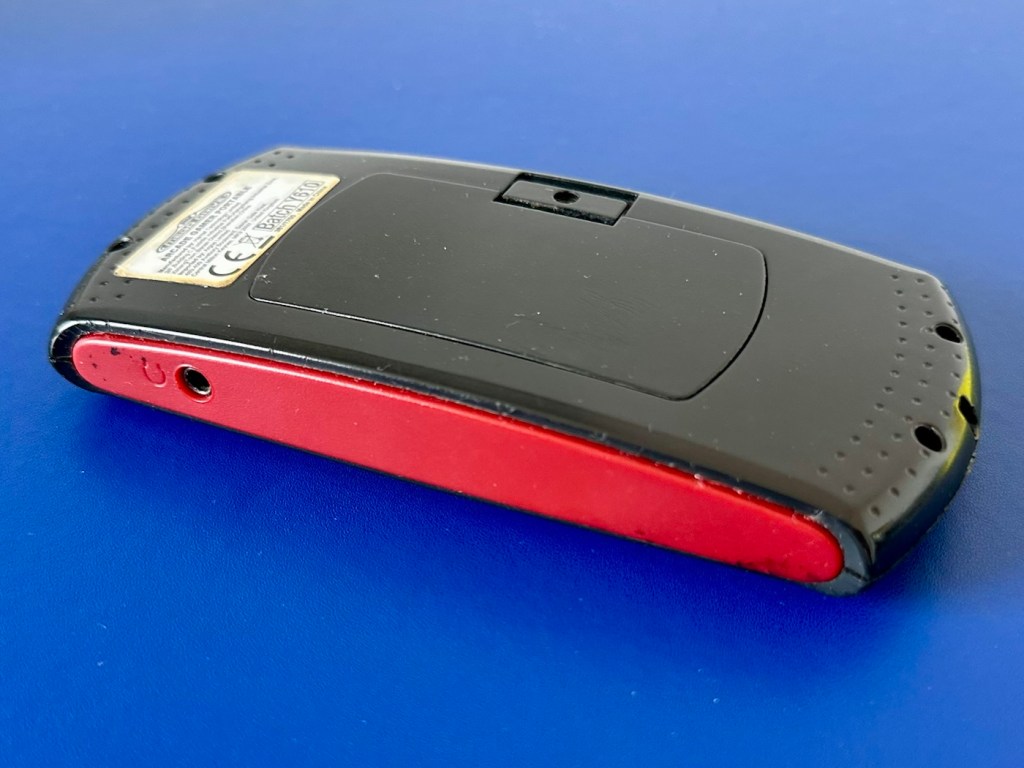
Front fasciaRear fasciaI think there may be a problem here
Let’s just say I paid considerably less than the price tag on the rear of the unit.
These handhelds were sold as emulation devices usually preloaded with games, between 20-80 games were the norm, I believe this is a 30 game option, if the information that is left of the previous price tag is to be believed. They were originally sold within the UK by the national retailer – Argos, and it originally retailed at a price of £29:99GBP.
A little about these units:
The AtGames Arcade Gamer Portable is a licensed, handheld “console-on-a-chip” manufactured around 2008. Despite the common inclusion of “Mega Drive” in some regional retail listings, it explicitly emulates Sega Master System (8-bit) and Sega Game Gear games rather than 16-bit Mega Drive/Genesis titles.
Game Library: Features 30 pre-loaded games. Notable titles include Sonic Triple Trouble, Sonic Chaos, Alex Kidd in Miracle World, Golden Axe, Ristar, and Tails Adventures.
Hardware Limitations: It relies entirely on emulation software and lacks a traditional cartridge slot. The d-pad and face buttons feature a modern 6-button layout, despite the underlying 8-bit games only requiring two active buttons.
Audio & Video: Uses a built-in mono speaker and a bright 2.4″ color LCD screen. It can plug into standard TVs via an AV output port, but it does not support modern HDMI connections directly.
Google
So here we have an unhealthy unit from 2008 requiring quite a bit of work, if it can even be repaired at all. It may just be too badly damaged to have a successful outcome.
Why am I wasting time on what was a relatively inexpensive item in the first place? And there lies the crux of the issue, in our throw away society this is the attitude we’ve all come to expect and to live by. It’s not a good attitude, there are probably millions if not billions of similar items world wide that have suffered the same fate, “it’s knackered, just chuck it and we’ll get another”. It’s a bad attitude that we need to step aside from. If I can at least reverse the attitude of one person and get them to explore the possibility of a fix to preserve an item and to save it going to waste, then I’ve achieved my goal. That’s why I’m wasting time on it.
Let’s await its arrival though, so I can carry out a full assessment.
Assessment:
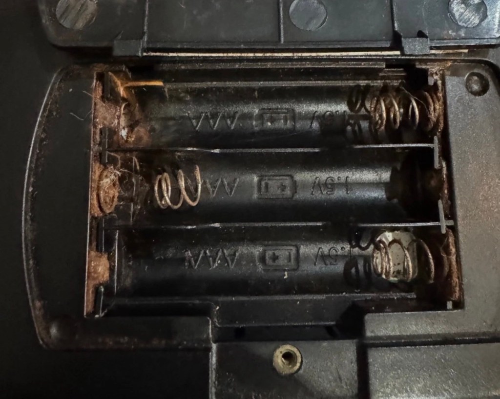
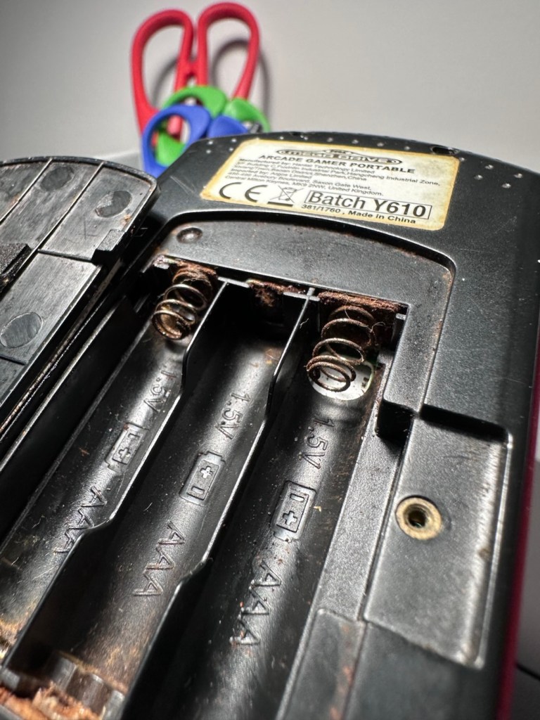
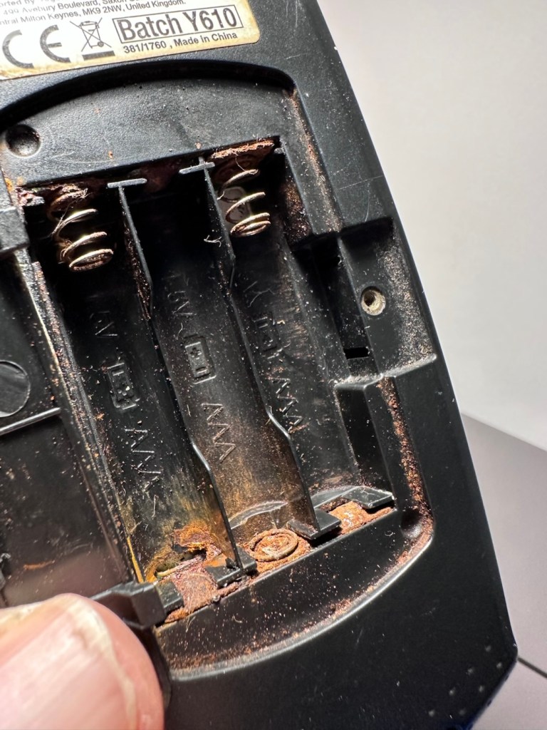
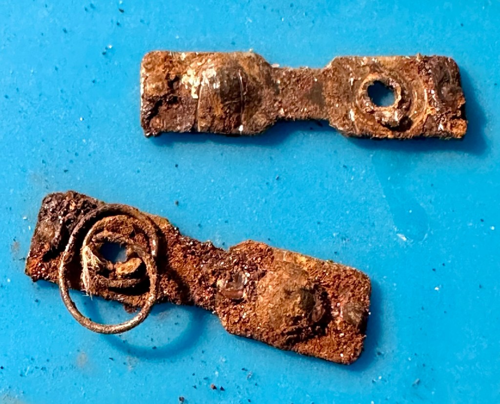
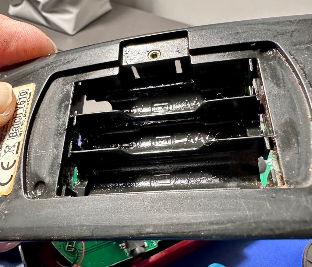
It’s arrived. It’s looking a tad tatty as expected, and those battery terminals are totally corroded. I’m not going to put any power into it at this point as I know there will be no response. I just hope the corrosion doesn’t go much deeper. This is all rust, not battery acid.
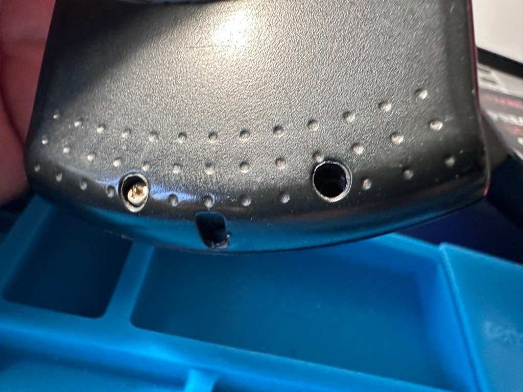
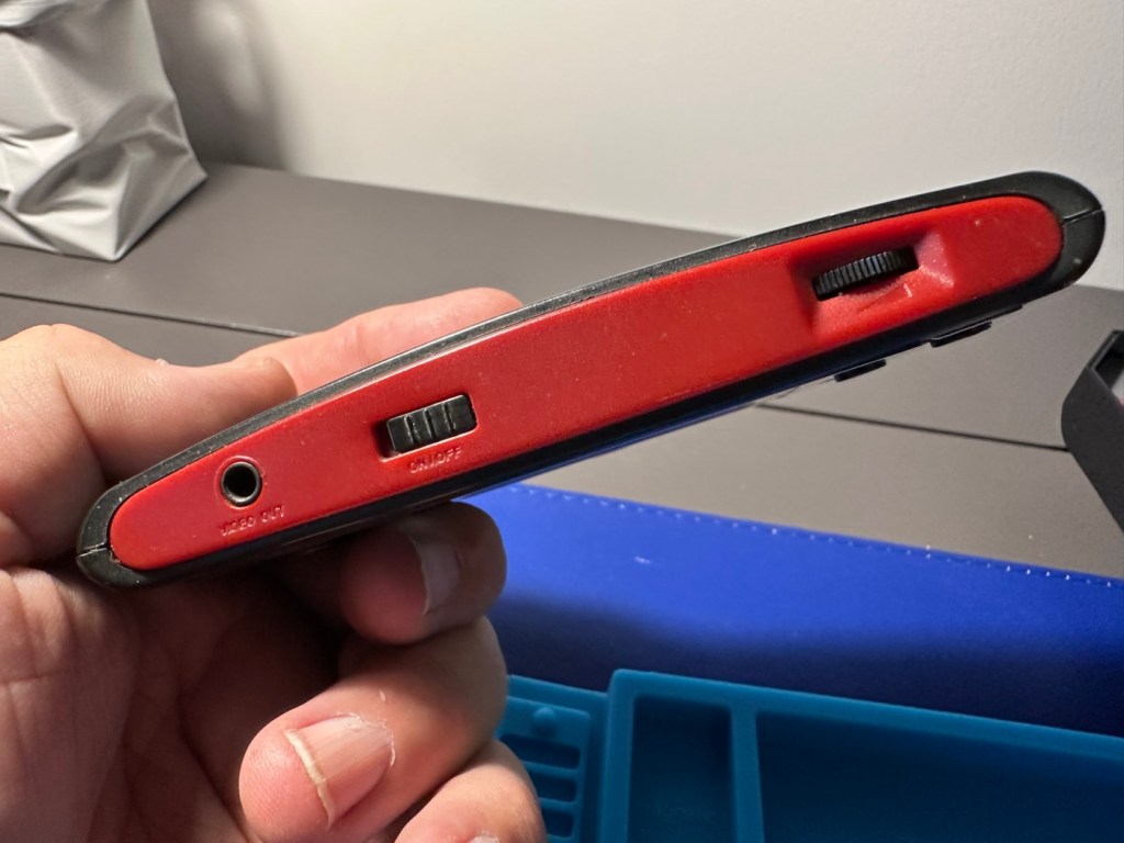
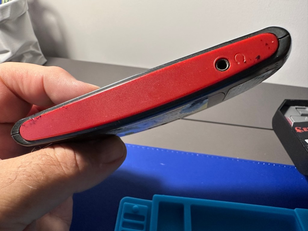
Looking well usedOld stickersMissing screwTop controls Bottom ear piece socketLook at that rusEverything here is rotted
We’ve got to get the case separated so that we can review the surprises inside that I suspect are waiting for me.
Repair:
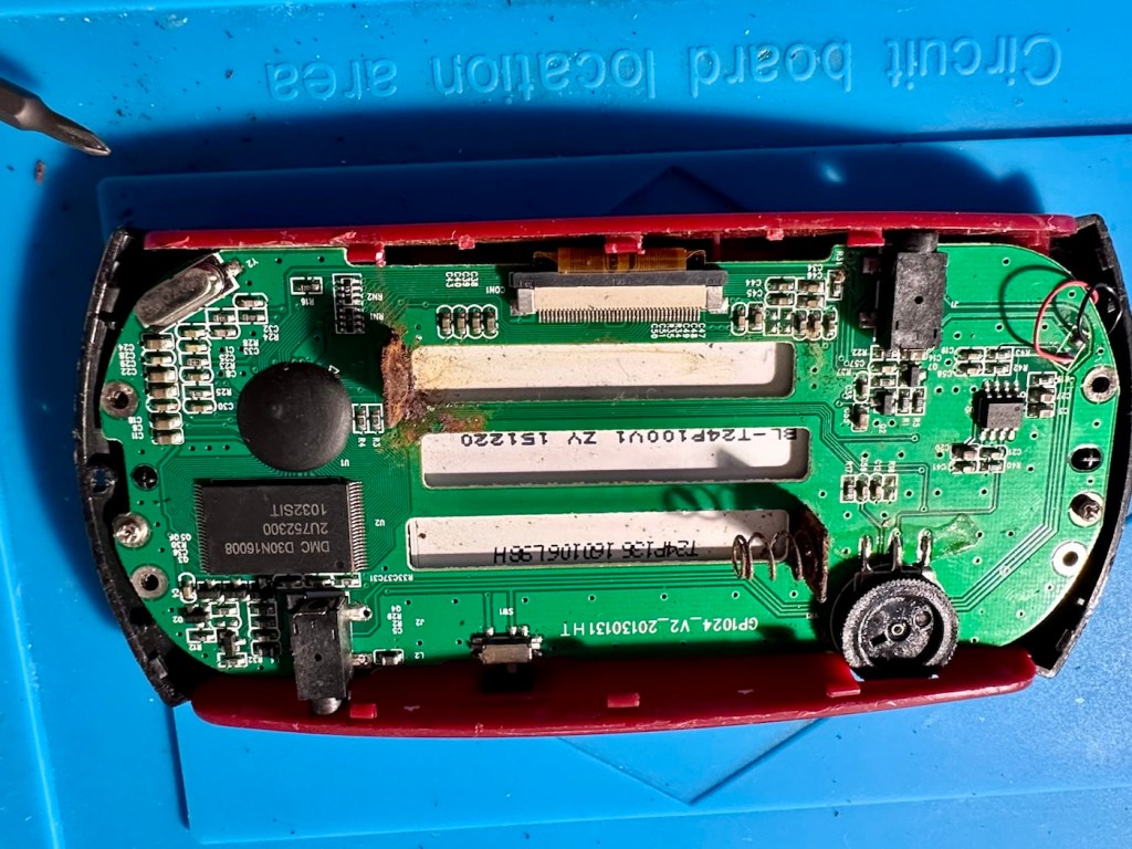
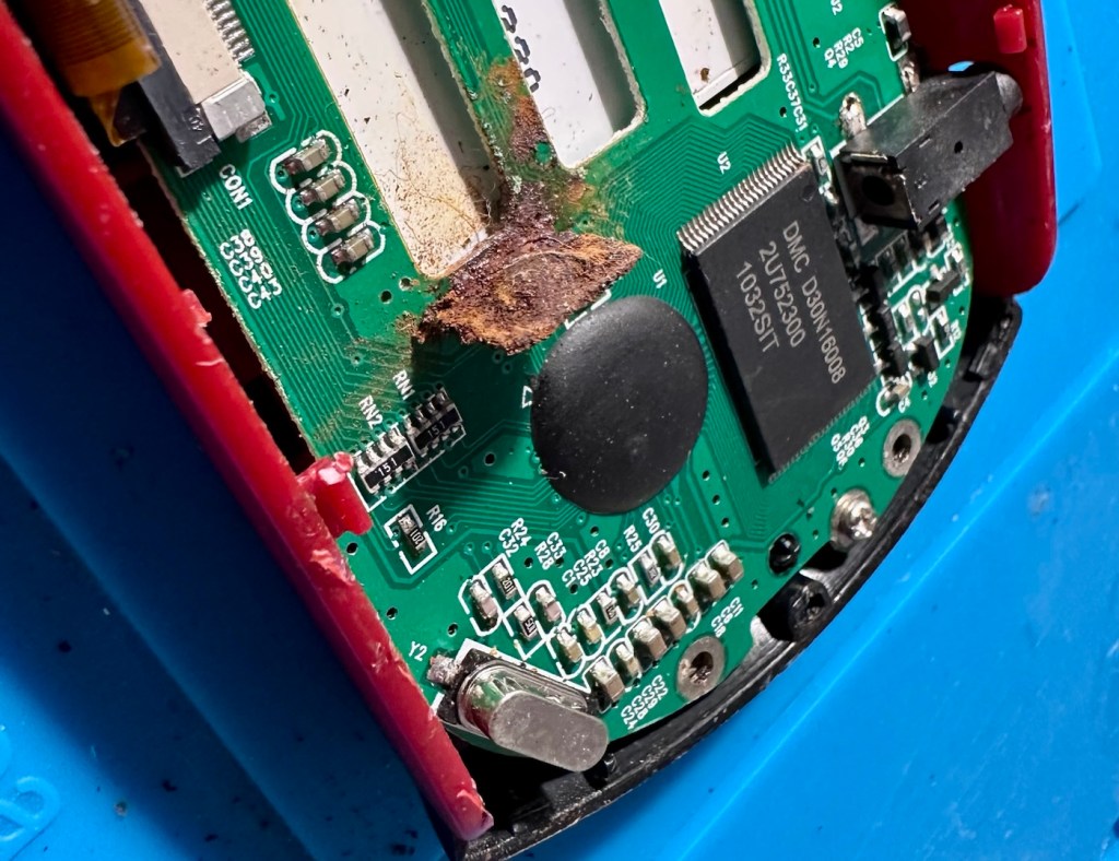
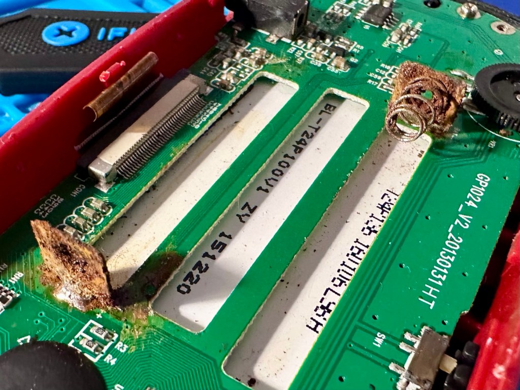
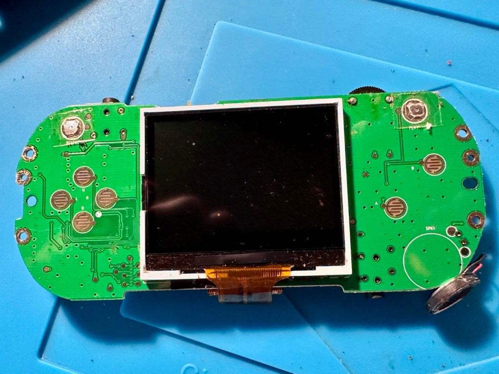
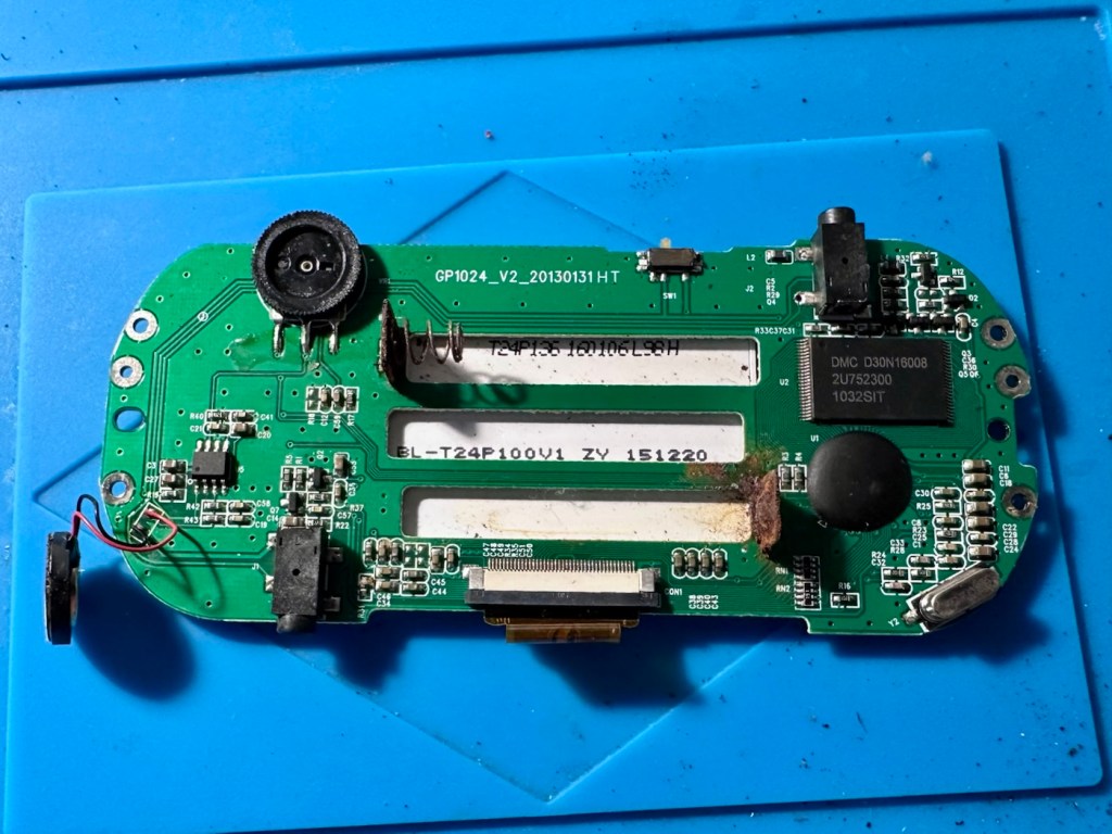
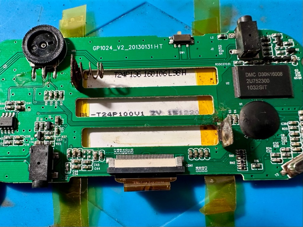
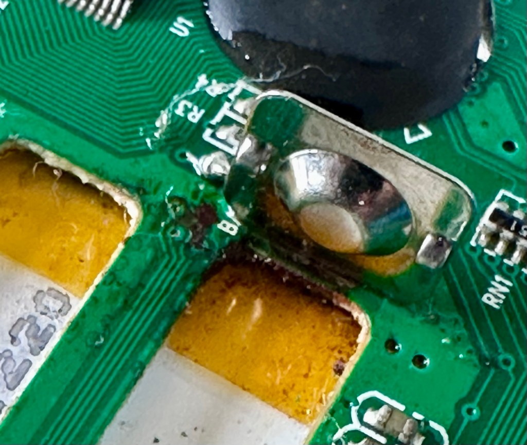
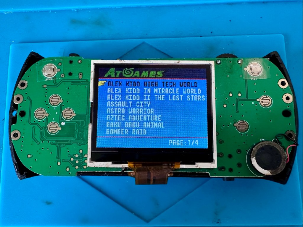
With the cases separated the extent of the damage can be seen. The rust has also completely damaged the two terminals on the main board.
The back of the main boardRusted positive terminal Both terminals destroyed
My main concern here is that directly below the terminals is the screen. I’m hoping the source of the problem hasn’t gone any further.
And luckily the terminals are where the rust issue ends.
Screen area and front of boardRear, damaged area
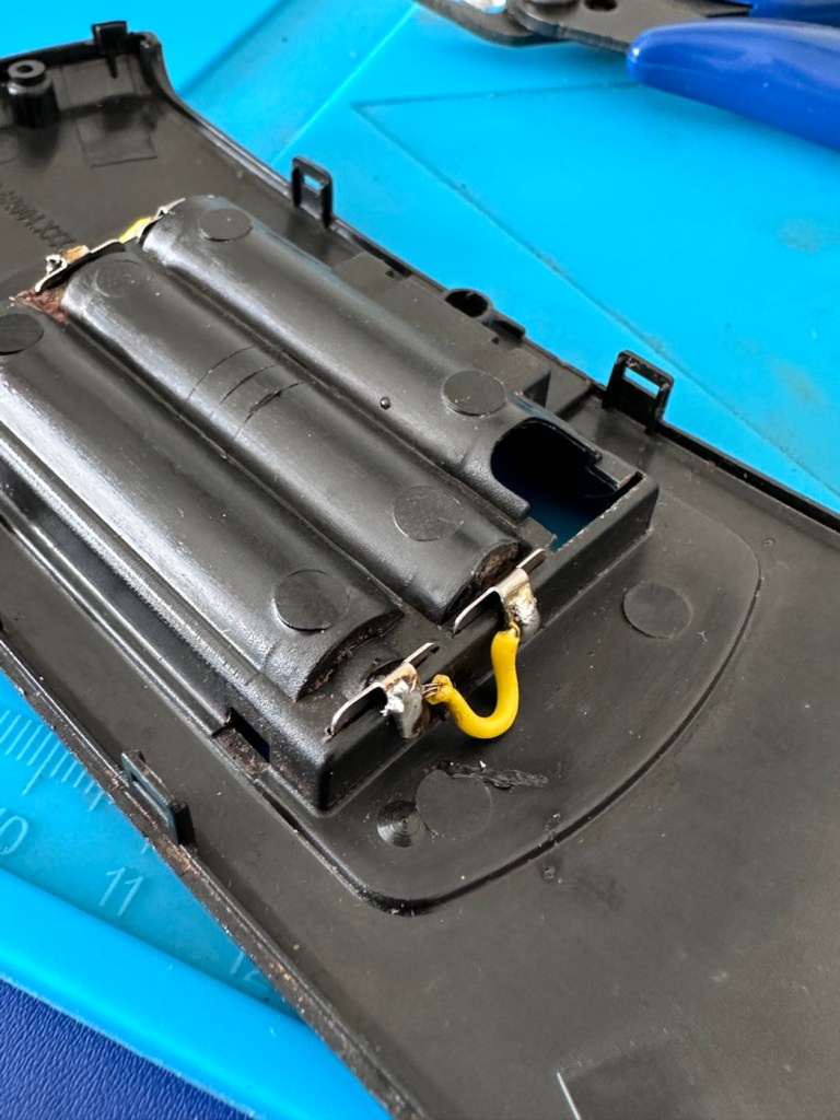
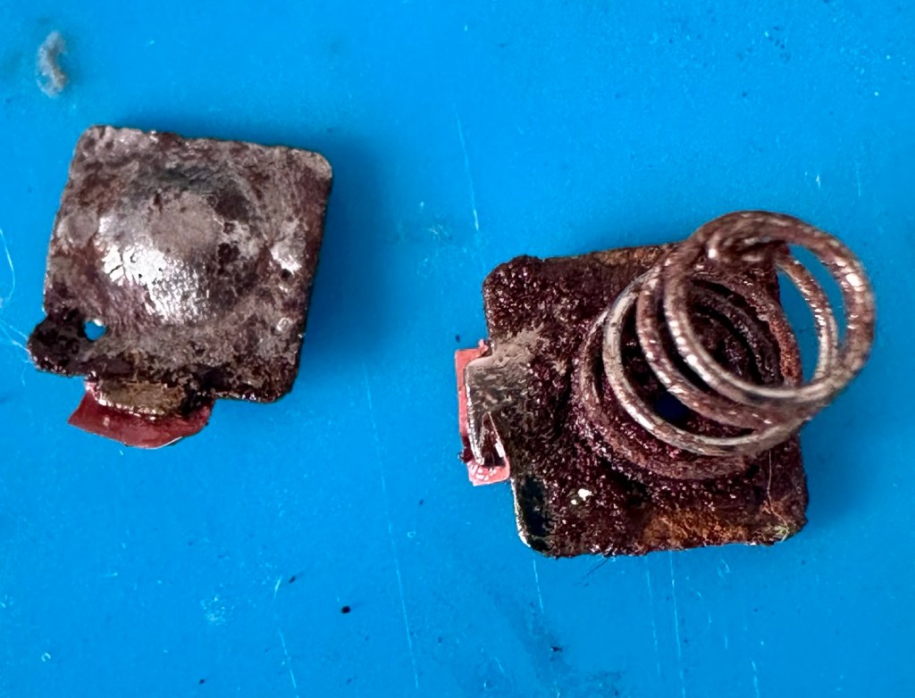
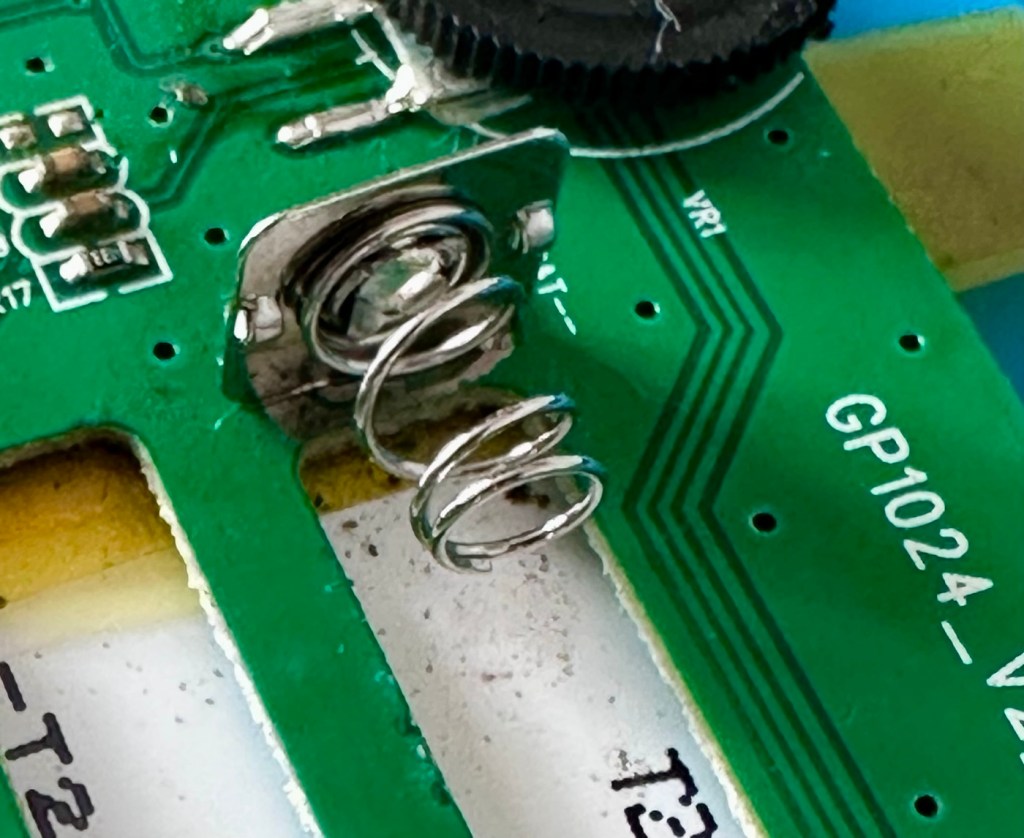
Ok, first thing I do is remove the rusted battery terminals from the battery compartment and then give the internal shell a thorough clean. I then install fresh terminals and add a couple of jumper wires as I don’t have and double type battery contacts. This is more than sufficient.
Corroded contactsShell cleanedNew contactsNew contactsJumpers added each end as I have no double terminals
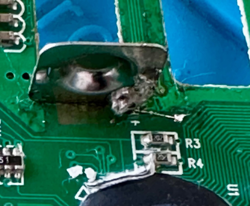
Next I need to get the two terminals off of the board, I use a soldering iron for this, and as I’m going to produce a little heat in the area I mask the area between the battery contacts and the screen with a little Kapton tape to give some protection, I could have removed the screen completely at this point, but as I was using the iron and not hot air I didn’t class it as necessary.
Kapton tape under terminals
However, as I removed the two terminals, it became obvious that I would have to remove the screen as the old terminals took the connector pads with them and damaged some of the traces. I was going to have to carry out a more complex repair.
The old contacts with pads attached New negative contactNew positive contact
The contacts had to be fastened from the rear of the board, so for this reason it was good that the screen was removed. The screen is quite delicate and is secured to the board with a ribbon cable that had to be detached, and double sided pads that had to be manipulated to release the screen from the board.
I did some testing with the multimeter and there was a good contact on the earth side. However the positive side was dead, no response. Closer examination of the board under the microscope showed that the trace between the positive terminal and a nearby Via point, shows that the trace had also been removed severing continuity. Using a grinding pen on the appropriate Via, allowed me to expose some copper, I was then able to use some flux and apply the tiniest dab of solder. The next stage was to utilise some trace repair wire, only 0.10mm thick. This is like trying to solder a piece of hair, it really is that thin. I was able to connect the wire from the base of the positive terminal to the via and testing proved that the continuity had been restored.
That tiny 0.10mm trace repair
I tidied this area up by adding a touch of UV curable solder mask, to protect that very thin wire from corrosion or being caught while re assembling. It cures in just over a minute under a small UV light and becomes quite solid. It’s good for this purpose.
So now that all continuity on both the negative and positive sides has been restored, I just connect the battery chamber for a quick test before reassembling it all.
And it works.
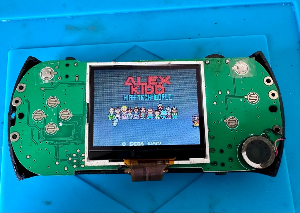
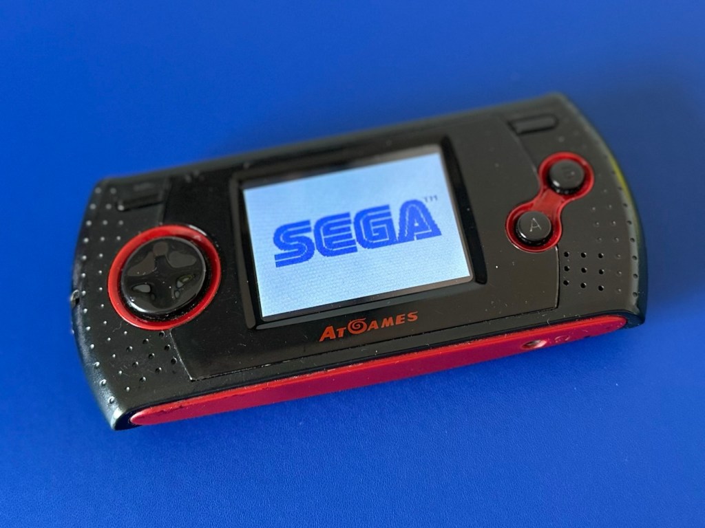
It springs into life
We have sound and we have vision. All that is needed now is to fully assemble the case to see if all the buttons and connectors are working as well.
Result:
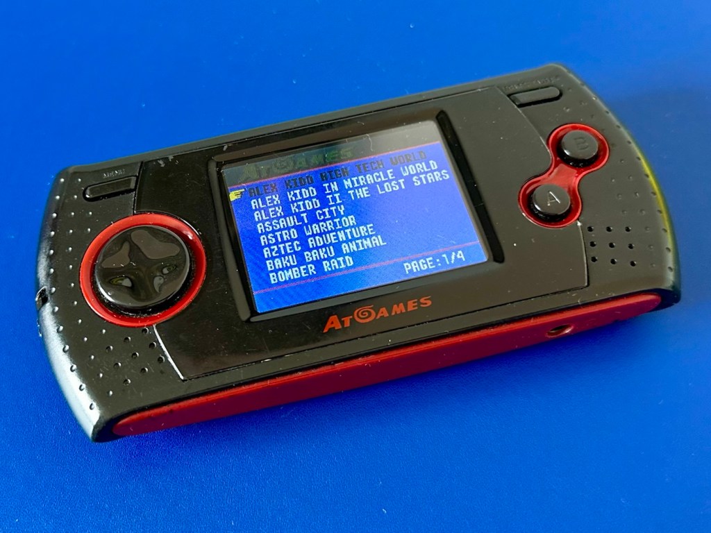
And they are. A quick test shows that all buttons and connectors are in a perfectly good working order, a quick polish and this unit is looking good.
Front RearTopBottomAll games appear and play fine, sound is excellent.
Really pleased with this repair, it was in a very sorry state of repair. However a little persistence and time and I have brought this little unit back to life.
I can understand the seller wanting to dispose of it and I suspect if it hadn’t of sold it would be on its way to landfill. I’ve prevented that and it’s a small win for me as this game will now go on to be used for a few more years to come.
A good result, a good repair and a happy me. Who could ask for more.
Many thanks for passing by. It’s always very much appreciated.
I recently wrote about a decentralised radio network called Meshtastic. Here I attempt to build my first Mesh node using a kit, and by also printing a 3d case.
I recently posted an article regarding a low power decentralised radio network that you can read about here: Meshtastic
That post was an introduction to the mode, this post is my first attempt to assemble and program the equipment, and to try to create a presence on the Meshtastic network.
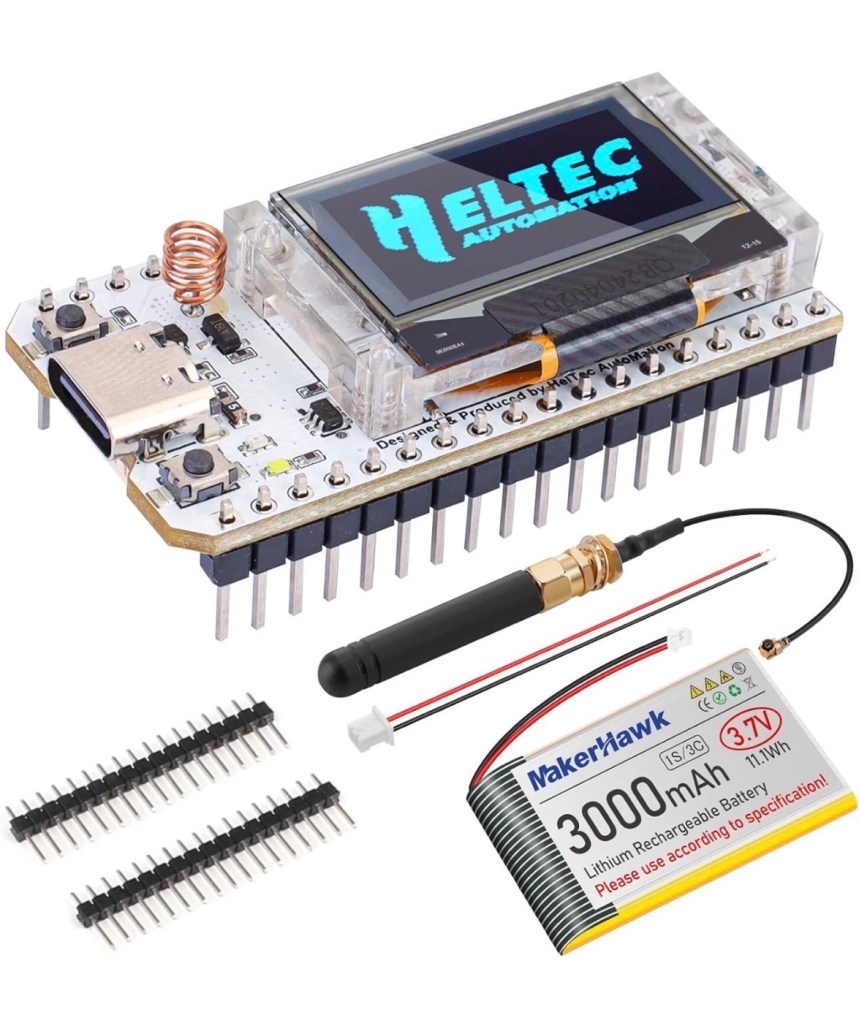
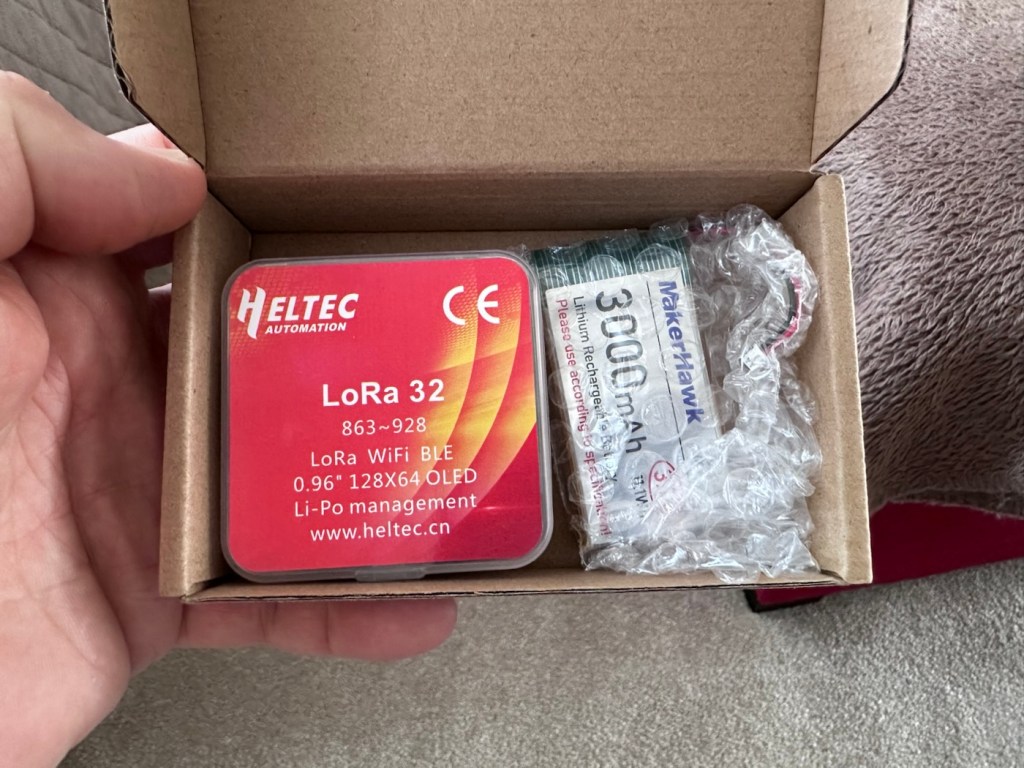
I’ve dived in and purchased a basic starter kit, the Heltec V3, and a separate GPS module, it’s my intention to install the GPS module once i get this up and working. The whole kit you see in the picture below is available in the UK and cost me a total of £34:19GBP. Other kits are available for a lower cost if you are prepared to await the delivery from China, however with my impatience on overdrive at the moment I just had to go ahead and buy it. That said i don’t think it’s too bad a price to pay for its combined parts.
The purchased kit
Preempting the kits arrival, I’ve downloaded a case from Makerworld by a designer called: @gux2K3 that I’ve uploaded to my 3D printer, it’s a basic case, but this purchased kit should fit it perfectly. It might not be sufficient for when I get the GPS module, but I’ll cross that bridge when I get to it.
The original case design courtesy of @gux2K3
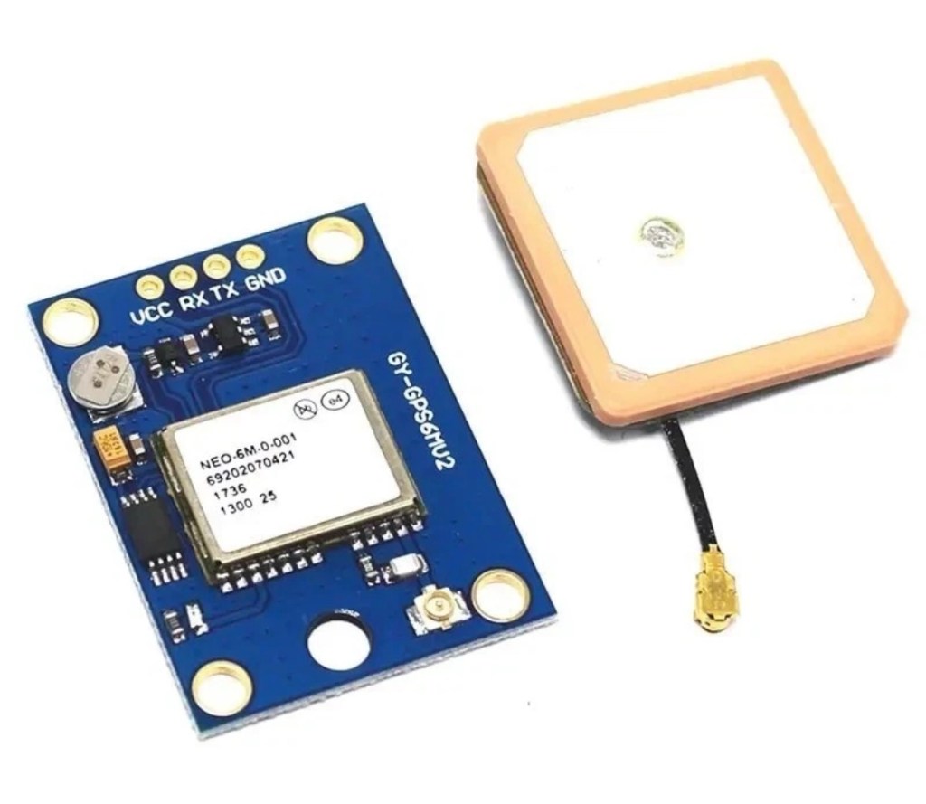
The GPS kit I’ve purchased
I have purchased the separate GPS module, and I will have to do some soldering to get this working. It will not fit in this case as I have already stated, so that upgrade will be saved for a later post.
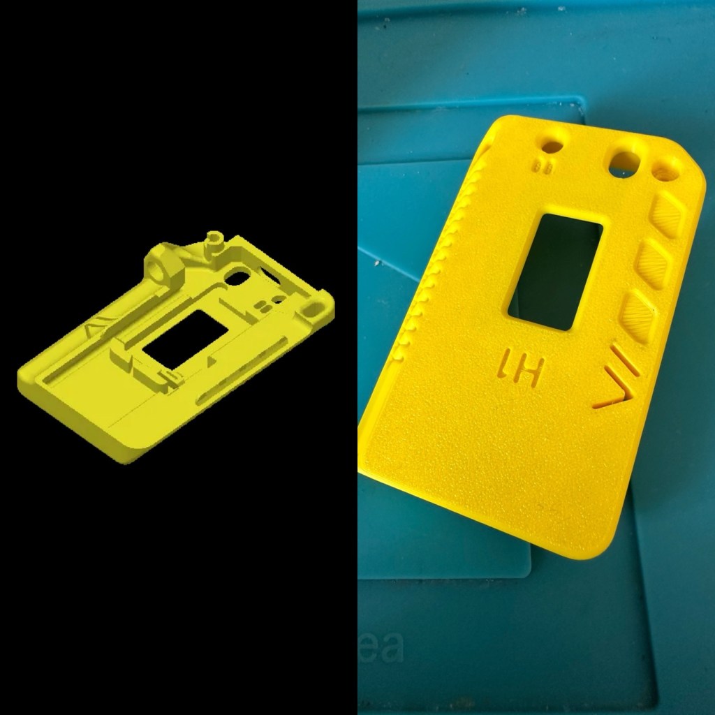
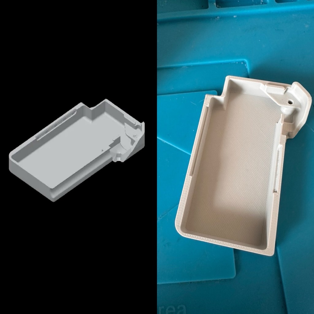
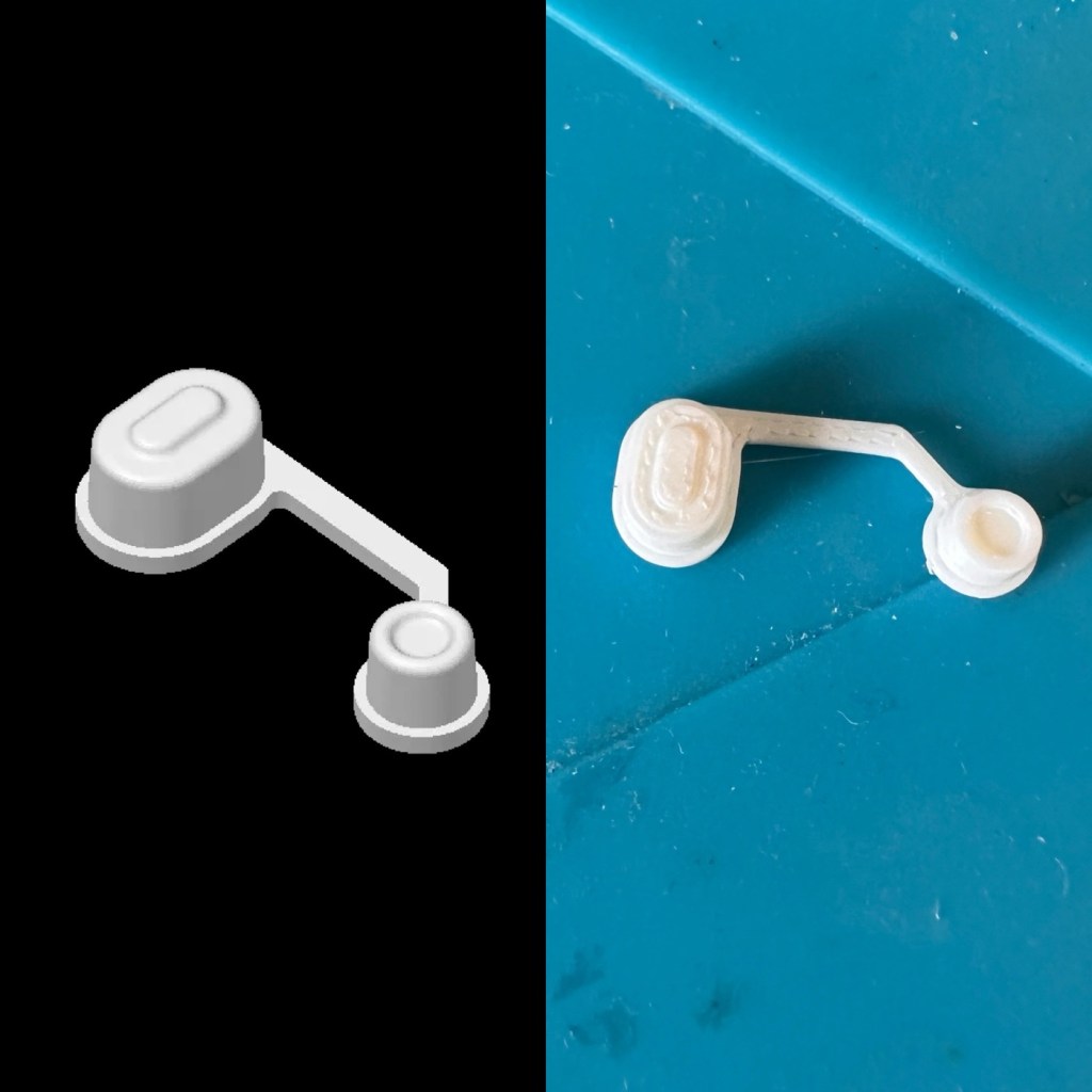
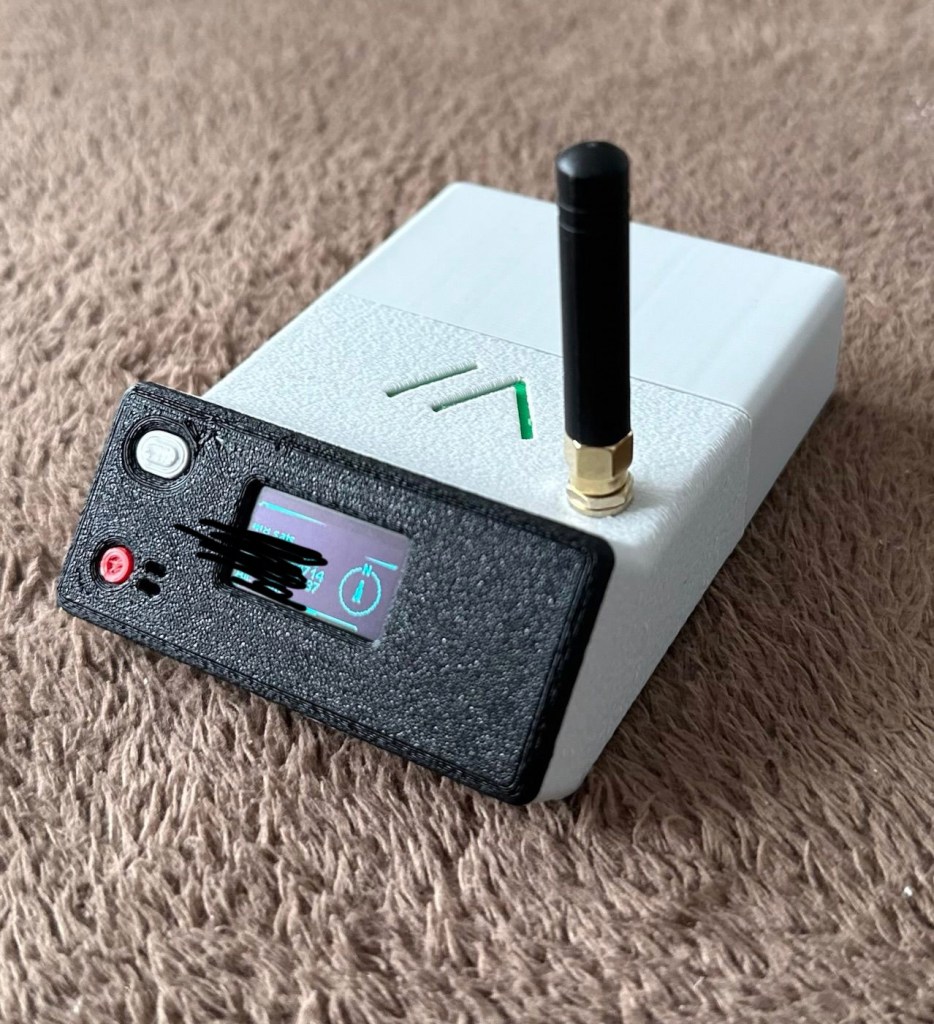
I want a basic slightly different colour scheme for my case, and below you can see a combination of pictures showing the original print plans and what the final piece looked like. It’s a three piece case, and I had to print this case on three different runs to get the different colours.
The print preview and finished items
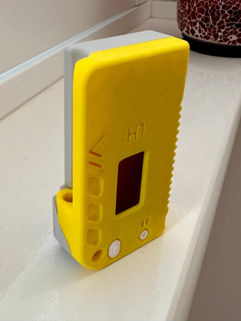
The finished case has been assembled I now just need to await the arrival of the kit for its installation.
The finished case, just awaiting the electronics for inside
For those of you who haven’t referred back to my original post, here’s a very brief description of what Meshtastic is all about, there are also other choices and platforms to operate with using Meshcore and Reticulum as examples, so here goes….
Meshtastic is an open-source project that allows you to build decentralized, off-grid text messaging and GPS tracking networks using small, inexpensive LoRa radios. Operating on license-free frequencies, devices link together as a “mesh,” automatically passing messages from node to node without relying on cell towers or the internet. In the Uk Meshtastic operates on the 868Mhz band.
Because they are walkie-talkie style text networks, they don’t support voice or video, but they are fantastic for hiking, emergency preparedness, or team coordination.
Other Off-Grid Mesh Options:
If Meshtastic doesn’t quite fit your use case, there are several alternative protocols and ecosystems built on the same underlying LoRa radio technology:
MeshCore: A rapidly growing alternative. While Meshtastic acts as an “ad-hoc” network where every device handles forwarding, MeshCore allows administrators to set specific device roles like stationary repeaters or personal companion radios. This reduces network congestion, making it highly reliable for structured urban networks and tactical operations.
Reticulum: A highly advanced, open-source stack built for extreme conditions and censorship resistance. It is more modular than Meshtastic and supports multiple types of underlying hardware (not just LoRa), but it has a much steeper learning curve.
GoTenna: A commercial, plug-and-play solution. Unlike the DIY nature of Meshtastic, GoTenna pairs pre-built, proprietary hardware directly with your smartphone app. It’s easier for beginners but lacks the massive community, range expandability, and customization of open-source projects.
Amateur (Ham) Radio / APRS: If you are willing to get a license, Automatic Packet Reporting System (APRS) operates on designated VHF/UHF frequencies. It allows you to send text messages and GPS beacons over vast distances using commercial handheld radios (like those from Kenwood or Yaesu) via established infrastructure rather than a localized mesh.
Assembly:
Ok. This isn’t that difficult and should be quite straightforward. The thing to remember is that the antenna MUST be attached to the board before power is applied. This is because the unit turns on and starts sending a signal as soon as power is applied, and without the antenna attached these units are renowned for burning out components for such a basically overlooked and simple step in the assembly process.
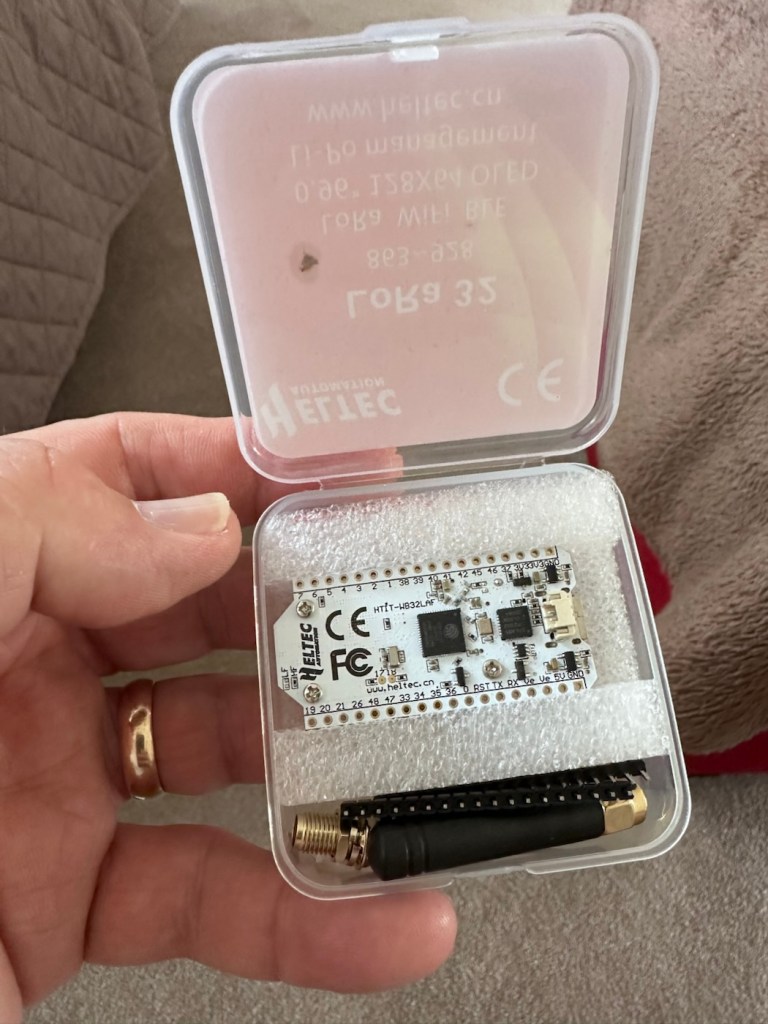
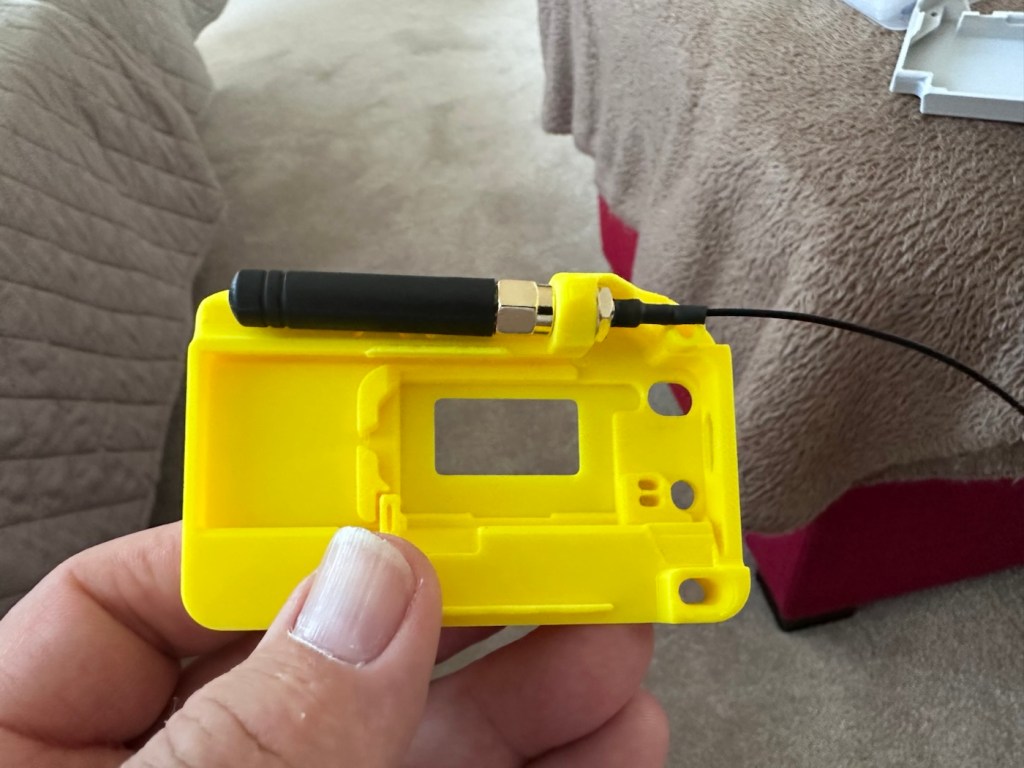
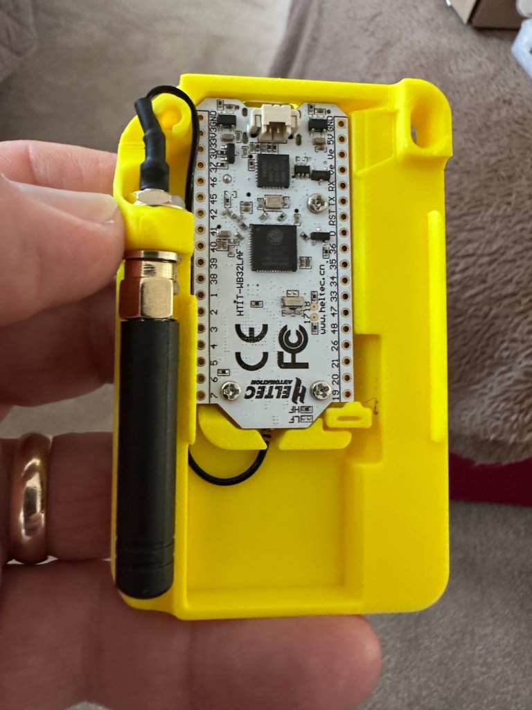
The whole thing is clicked together in about 5mins flat, the one task that takes the longest is the fastening of the aerial into the case. If you have sausage fingers like me, it can take a little time and a few attempts to ensure you get the screws set up correctly to ensure you don’t double thread the item. Here’s some pictures from unboxing to full assembly.
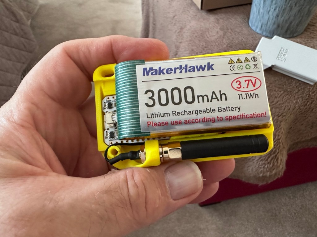
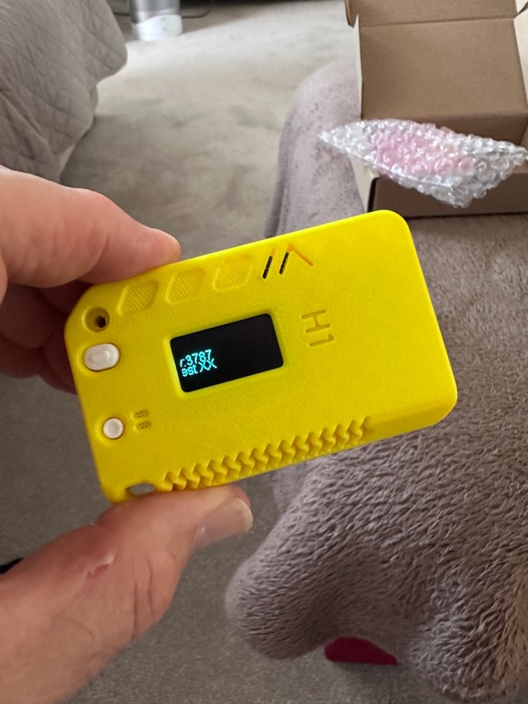
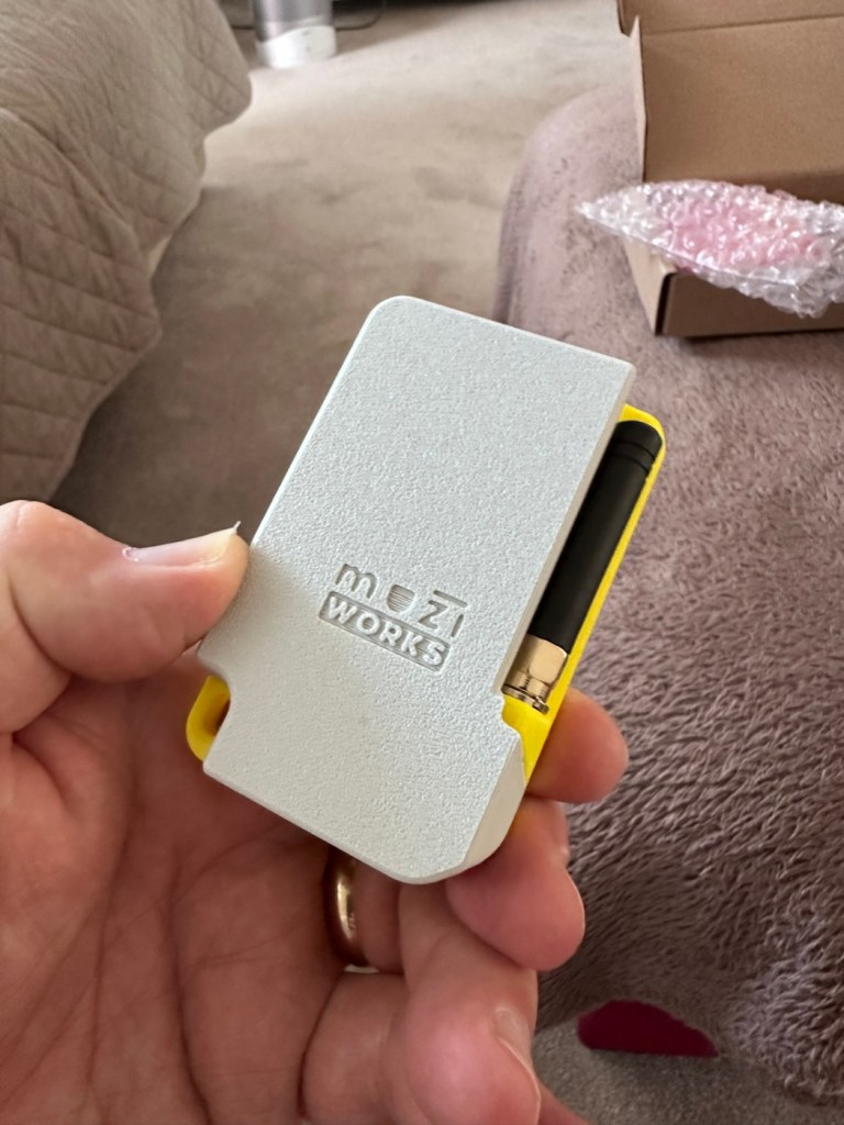
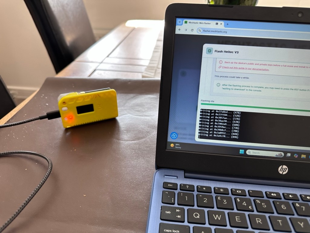
The box The plastic case can also be used as a basic caseAerial inMain board inBattery attachedBooting upRearFlashingOperational
Once assembled the next thing to do is to flash the board with the correct operating software from the Meshtastic website. I’m not going to go into much detail with this as there are many good instructional videos out there that already have this covered, here’s one that I used to get me started:
Setting up Meshtastic on the Heltec V3
I’ve been using this node for around two weeks now, just testing its capabilities and seeing what the life span of the battery is. Here where I am in my part of the East Midlands, take up and usage at the moment is quite poor and in fact there is only one other node near me in use, and that one is being used infrequently to say the least. So for me, it’s just a waiting game to see if any other nodes appear as word gets out about the system, and basically if any is interested.
I have only made one contact within that time, a node that is about a mile away, and that’s it. There are so few nodes in my area, I believe i am only the third within a two mile range, and one of those is an unmonitored unit. but at least its a contact and proves the unit is working. It’s early days around here and a better mesh needs to be implemented. I’m sure in time as word gets about, and if anyone is interested that things will improve.
The thing of interest about this method of communication is that it’s purely off grid. Should every other form of communication cease for whatever reason then this is looked upon as an alternative for local “Meshed” communication. It’s a bit of a tin foil hat system in my personal view, I’m sure if someone in a position of power or tyranny wanted to shut the system down I’m sure that they could without too much trouble. It’s a good experimental system in keeping with similar practices that the Amateur radio network adhere to, however this system does not require licensing and is free for anyone to experiment with. And that’s the interesting part.
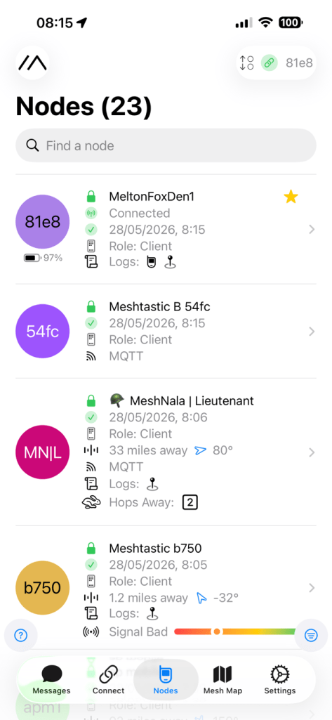
With the battery charged, and the system active my first “listening” session shows the following:
Here is where things become weird, and it’s the point that you realise that others are already stepping away from the true local message usage that was intended to try and make the system a longer range one incorporating the internet as a form of transportation for messages. This makes me scratch my head as surely the internet would be one of the first modes of communication to go down if there was some catastrophic event that took out traditional modes of communication? However, there is this mode that can be accessed called MQTT:
MQTT is a lightweight, publish–subscribe, machine-to-machine network protocol for message queueing/message queuing services. It is designed for connections with remote locations that have devices with resource constraints or limited network bandwidth, such as in the Internet of things (IoT). It must run over a transport protocol that provides ordered, lossless, bi-directional connections—typically, TCP/IP.[1] It is an open OASIS standard and an ISO recommendation (ISO/IEC 20922).
Wikipedia
Anyway, I had this setup, and I’ve now disabled it to ensure two things, that the system is true to its original intentions, and also to get a true idea of battery life using the most basic of setups.
Some things I have noted within the last two weeks are that if you are not in possession of a system with a GPS module, you then have to setup your node with a fixed location. This is absolutely no issue if your node is going to remain in a fixed position. However if you wish to take a node with you and move around, and let’s say you are 200 miles away from home, unless you go into your computer and reset the fixed location then you will always be 200 miles away from home but still showing as being “At home” hence giving false location information and giving anyone local to your new position false hope on them suddenly picking up a very strong signal over a long distance. Pretty much unheard of and impossible considering the power limitations of this system.
So one thing I will now do is attach the GPS module I mentioned towards the top of this post, to get accurate location information whilst mobile. There is a caveat here in that the power drain will be excessive for this battery and the GPS will greatly reduce its capacity.
Currently, with this node sitting in an upstairs bedroom window I am easily getting 24-36hrs from a single charge. Add to that a battery power bank I have with a solar charging capability I’m pretty much getting an almost endless period of usage. Weather has not been what I’d call particularly sunny recently, so I’d suspect capability would be much improved during summer months. I’ll just have to see how well this setup can work with the GPS system installed.
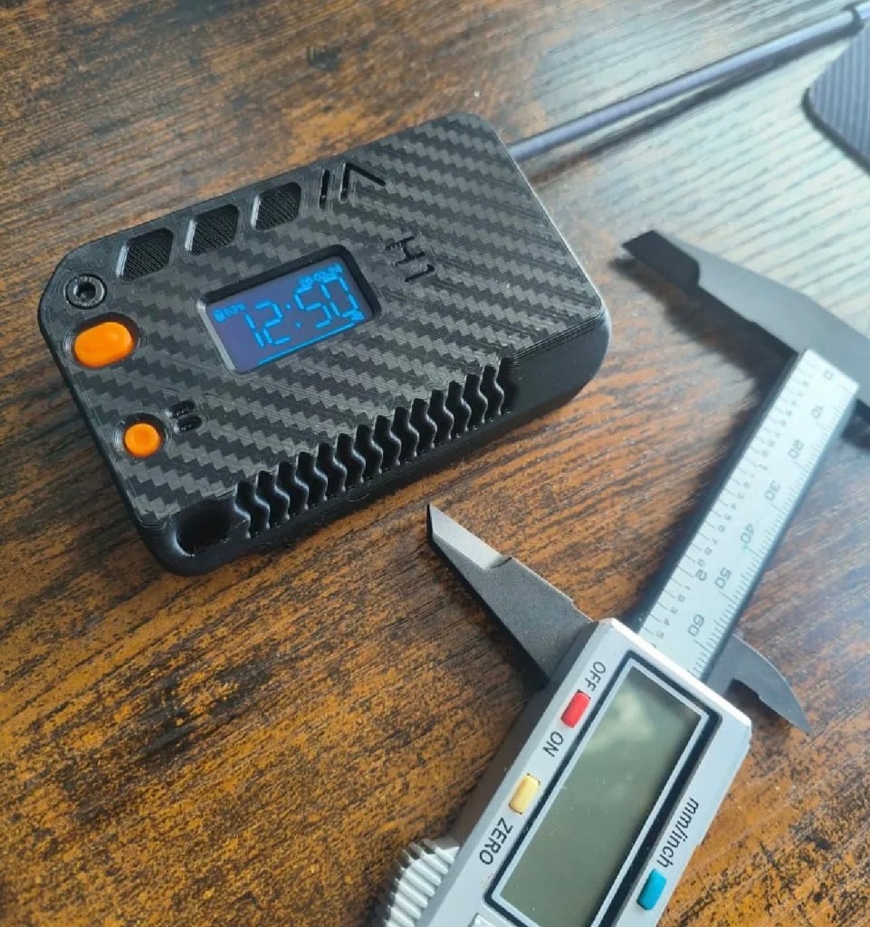
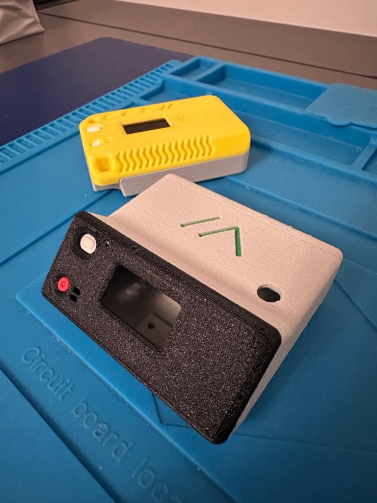
The current case I am using does not have room in it to facilitate the GPS board and antenna. For this purpose I have had to print a new case to house the unit in, and this is the barebones case pictured alongside the original case.
New case versus old
The old case will not be wasted. I intend to use that as a permanent fixed home base that I can use for testing the mobile one, and for building my own personal mesh system at home. The good thing with this system is that as well having public broadcast channels, you can also setup personal private channels for family and friends.
So let’s get the GPS setup.
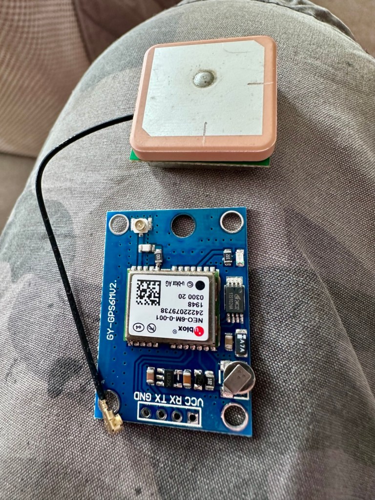
The GPS board comes as a two part package. One part is the actual main board whilst the other part is the antenna on its own small board with a wire to attach it to the main board.
The GPS unit
Here is where the fun begins as we are going to have to do some soldering of this unit to the actual main “radio” board.
In a nutshell this little video explains exactly what you have to do.
Setting up GPS on the Heltec V3
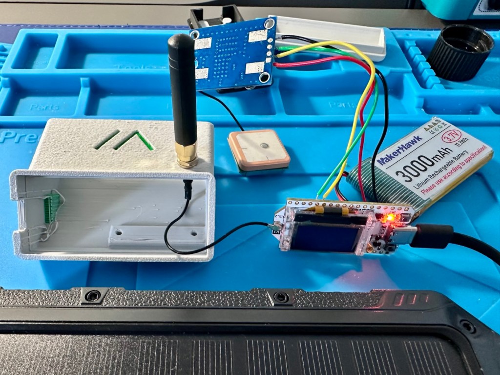
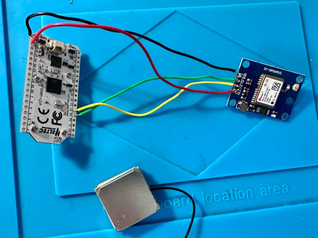
I’ve had to solder 4 wires that connect the main board to the GPS unit. These are only temporary at this moment, as I need to be able to sit all components comfortably within the casing. I may have to add a switch, however I’m exploring other options at the moment. I’ll get to the reason why in a short while.
The case, the main board and now a GPS module added
The four wires connect power, a ground, a receive pin and a transmit pin, there may yet be a fifth wire, I’m exploring that option as stated above.
The temporary soldered wires
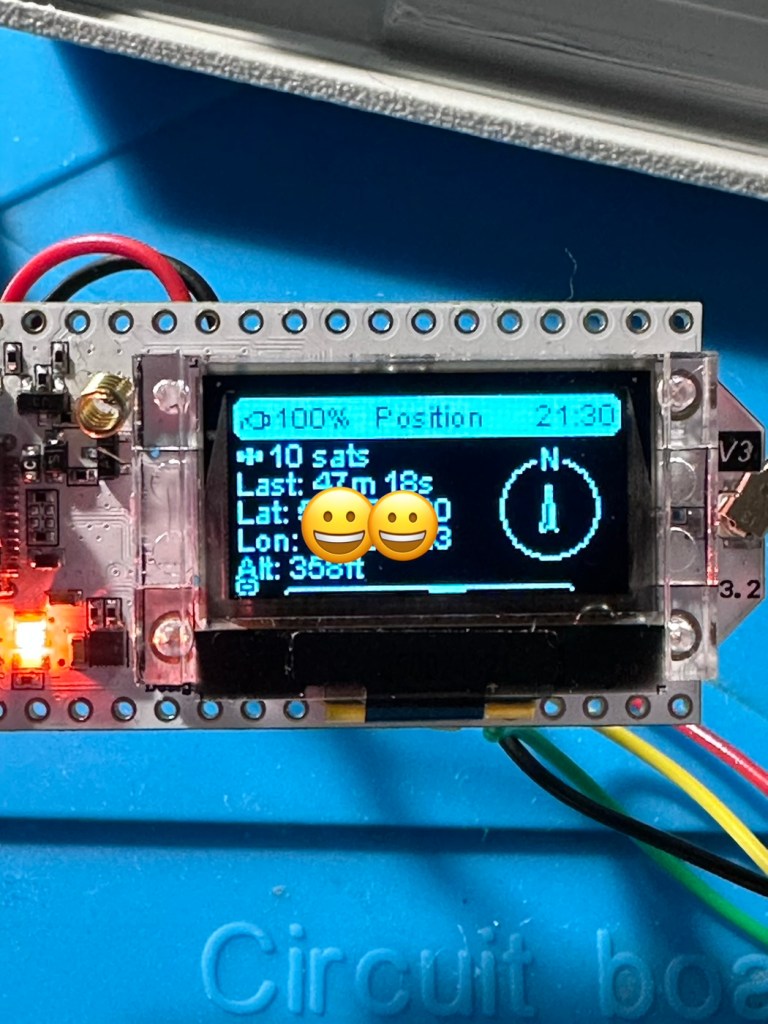
So does this work? I’ve charged the battery up to 100%, I’ve made some changes to the settings within the operating system and have turned the unit on. These system fires up and then a separate blue light on the GPS board flashes indicating that there is power to the GPS board.
All working
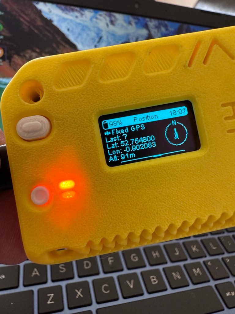
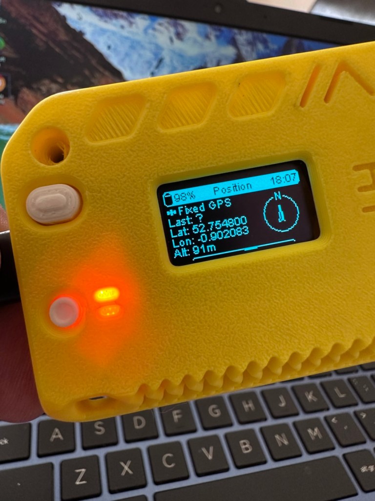
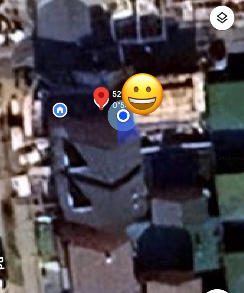
And then there is confirmation of 10 satellites being tracked, a height asl, and a longitude and latitude bearing, all seem to be working. But how accurate is the GPS reading? I put these readings into Google maps and the result is spot on. In the picture below the blue dot represents my phone location, and the red dot represents the GPS coordinates from the GPS module. Working perfectly👌. All smiley faces are just disguising the readings, much that I appreciate your reading of my shenanigans, I don’t have enough tea cups to welcome you all in 😂
iPhone position and GPS module position
Previously prior to the addition of the GPS module I did state that I was easily getting 24-36hrs of life out of this battery on a single charge. That is going to change quite significantly as the GPS module is a super power hungry beast. I’ve currently set the GPS module to transmit its position once every hour. To be honest I could probably transmit once every 8-12 hours as i am currently in a fixed position and not moving. If I were in a car, I might even look at transmitting the coordinates every two minutes as this appears to be the default setting for a mobile node, and that would certainly drain the battery in no time. It would probably be best practice in this situation to have the unit running on power as the car is moving.
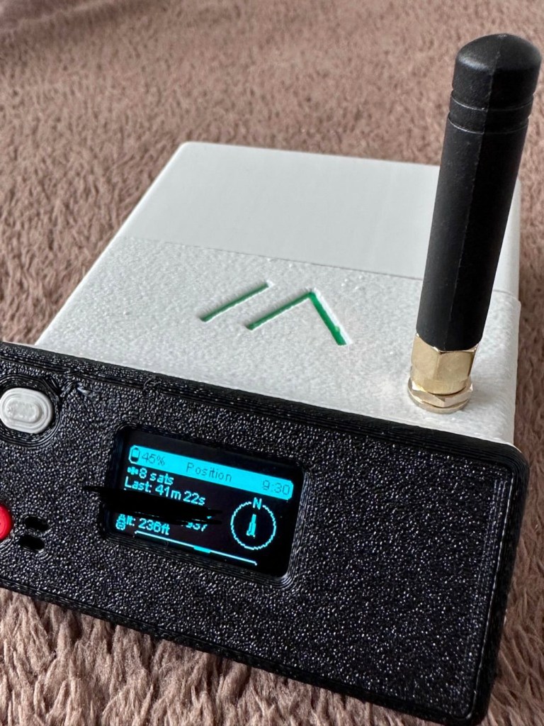
But I’m sticking with the hourly setting at present, just to do a basic drain test. This battery was on a 100% charge setting at 21:30hrs this evening as you can see in the photo above, I want to see if it will still have power 12hrs from now. No doubt power will deplete a lot quicker with the GPS module in place.
Depending on the results, this will help me decide if an extra wire or component or even both is needed within the circuit, and the reason for this is to be able to disable the GPS signal when not required. This modification in its simplest form can be as simple as putting a switch in the 3v supply wire, or by including a MOSFET (an electronic signal switch) into the circuit to allow the main board to automatically turn the GPS on and off via settings built into the software. I’ll make my decision when i see the results after I rise in the morning, and also depending on having the required components somewhere within my spares boxes.
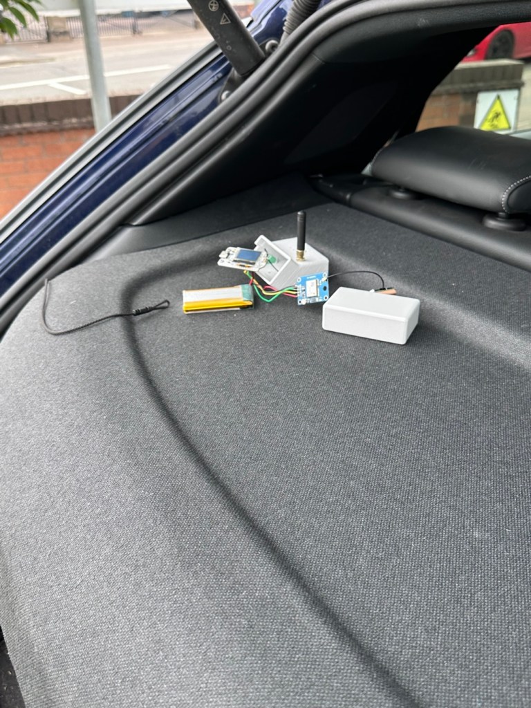
About 7am the following morning (Approx 10hrs after setup) the power level is sitting at a comfortable 50%. The last GPS broadcast was at 02:37 in the e morning, I don’t know why this was as it’s set at a one hour cycle, I’m not complaining, maybe it didn’t have a successful signal to lock on to? Who knows. I have to take my wife out on an errand at about 07:30 so I’m going to put the GPS signal to a two minute cycle, put the bare bones set up on the parcel shelf of the car and just see if it works.
Barebones in the rear of the car
And it has worked perfectly.
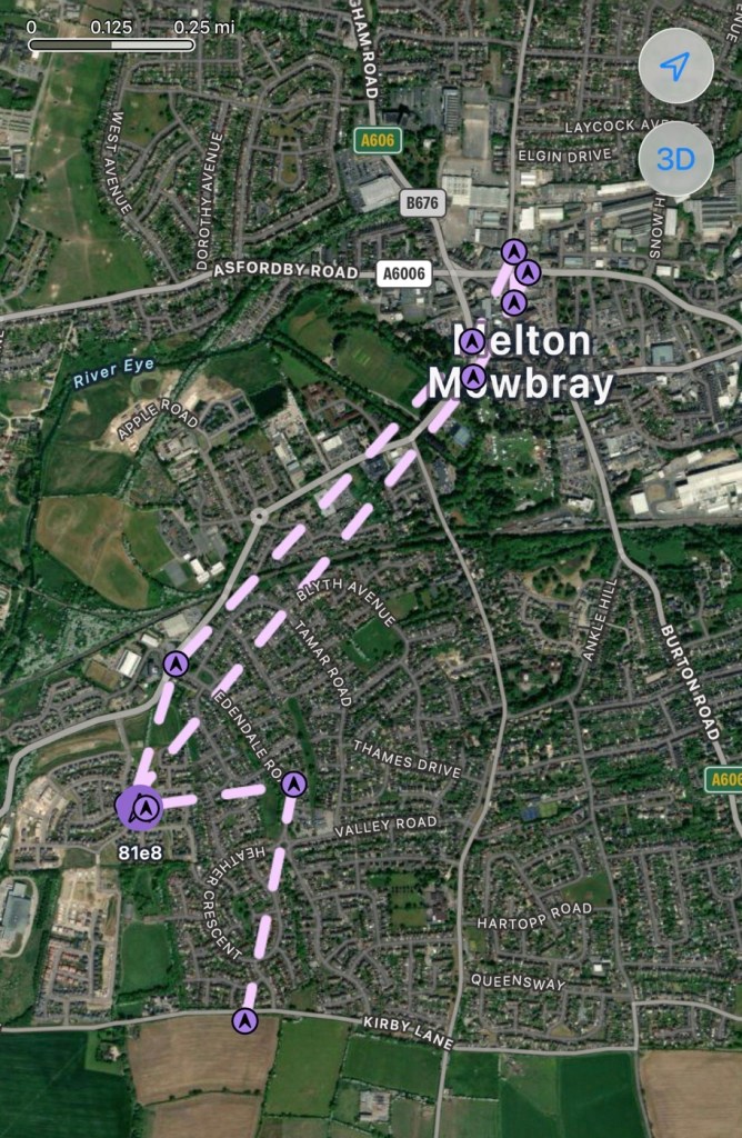
Log of the journey
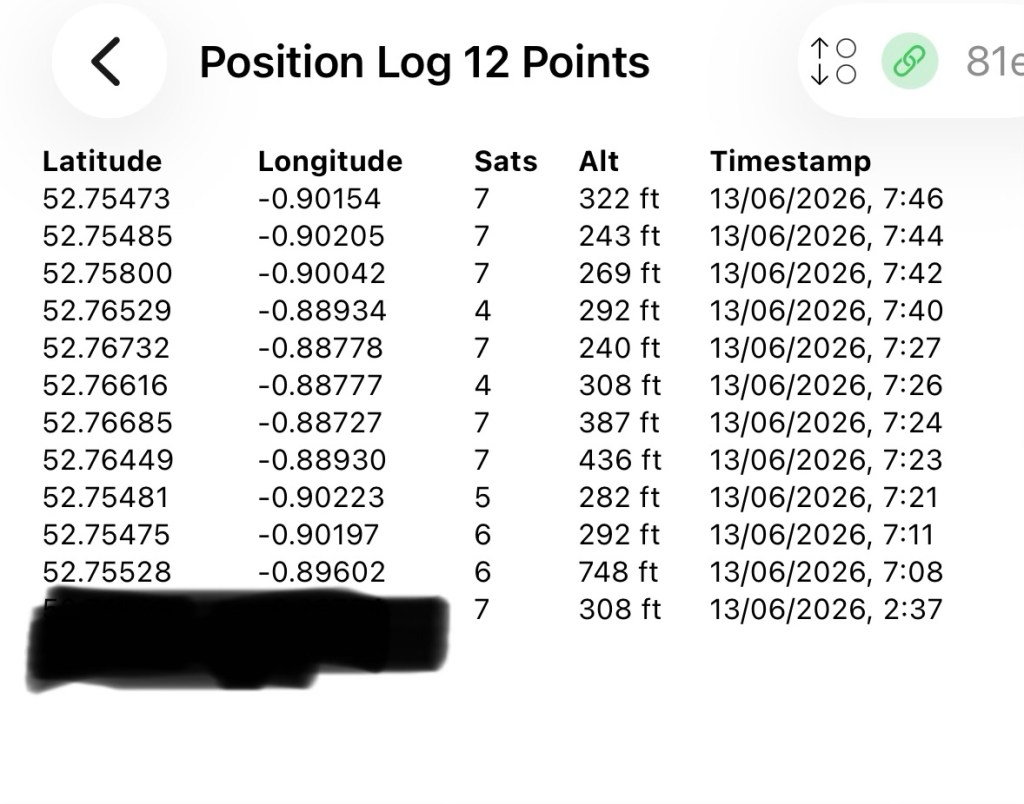
GPS log
In the GPS log above you can see how it has performed. The received data at 02:37 in the morning was the last on the hourly cycle, and then at 07:08 was the first of the two minute cycle prior to me switching it back onto a one hour cycle again at 07:46. I’m now going to leave it alone until we reach the 12hr mark and I’ll see how this small trial has gone during this period.
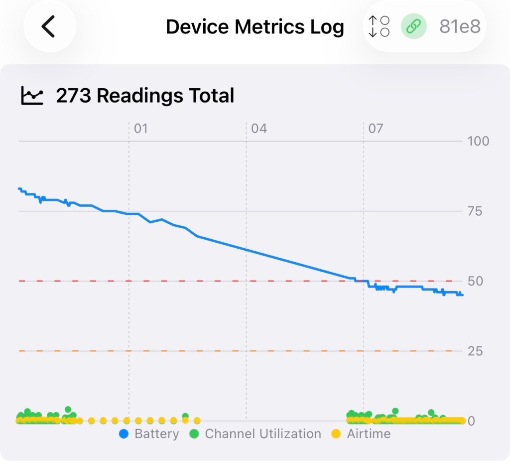
We’ve reached the 12hr post, and the power level is 45%. So over the 12 hr monitoring period with the GPS on a one hour cycle we have used 55% of the battery capacity.
If you look at this log of the diagnostics over this period you will see a gradual decrease in battery capacity (Blue line) with the only noticeable disturbance being when I turned the GPS to a two minute cycle at 07:08 this morning when I had to take my wife out.
Device metrics over 12 hrs
Overall it’s a pleasing result but I’d suspect even with a low usage of the GPS module I’d probably only be able to get 18hrs of usage maximum from a single charge using the GPS on a one hourly cycle. Using the 2 min cycle I’d probably struggle to get 12 hrs of use from a charge, maybe even less, compared to the normal battery life of 24-36hrs without the GPS module you can see that the difference in power consumption that is involved. As I have said previously the GPS is quite a power hungry addition.
But do you know what? The figures are pretty good to be honest. If I use the unit at home I will reduce the GPS signal to probably one cycle every 3-6hrs. If I’m out mobile I very much doubt I will be driving more than a few hrs maximum, so I can always switch cycle rates as required.
So. Do I need to add another cable or that MOSFET discussed earlier? Probably not, it’s not essential but sometimes it may be advisable or recommended to maintain anonymity so a switching system would benefit in those situations.
For the meantime I’ve just thrown the bare bones unit into its case with no proper spacing, as I’m going to take the unit out again today on a slightly longer journey for a family gathering. It will be good to see how it performs and to see if we can get any noticeable contacts in an area other than my home location. You never know that Meshtastic may have a greater following or uptake in that area.
And the journey out to the family gathering registered just fine. I’m confident and happy that the GPS addition has been successful.
The route to the family gathering
And guess what. There are even fewer nodes in use to make contact with here. I am, or appear to be the only one, it’s a lonely pastime at the moment.
The journey back home was fine and again the GPS worked as it should. Now to get the GPS power management installed, I’ve decided to go with the “N” type MOSFET option, I’ll get this installed, tidy up the wiring and get the case placement sorted. I’ll then just reflash the software to remove any glitches and then I will rename this node as my mobile option – (MeltonFoxMob – MEFM). I’m then going to get myself a second node to build and install, probably a solar node, that will become my permanent home installation node.
I’ve just purchased a couple of N type AO3400a Mosfets as I don’t have any in my spares box. Putting this in circuit will allow me a greater control of the power consumption via the units firmware.
It’s been tested over approximately 6 weeks now and to be quite honest, I’m not that impressed. There has been one single contact over that period, however the vehicle tracking option is ok (ish) there are some questions about the system turning itself off about half way in to a longish journey, but that could be down to me not having the MOSFET in place.
I personally think it’s a fad thing until it really takes off. I will keep my mobile unit and possibly a home unit in place to see just what happens. There is only one node working in my immediate area and I’m not even sure if that is monitored in any way.
These kind of systems have to start somewhere and they just need a few more people to pop on board and spread the word. If I turn mine off then it’s another potential possibility for the advancement of the technology that will have disappeared. I’m going to be persistent with it for the foreseeable future and hope others come on board. But at the moment I’m not overly impressed. Things can only get better as they say.
Thanks for passing by. It’s always most appreciated.
Apparently the puzzle can be completed in 18 moves. Well, can it?
I remember this fad coming into school the first time around. I never had one, never particularly wanted one either, probably as my attention span was never that concentrated and I’d probably have ended up throwing it at a wall.
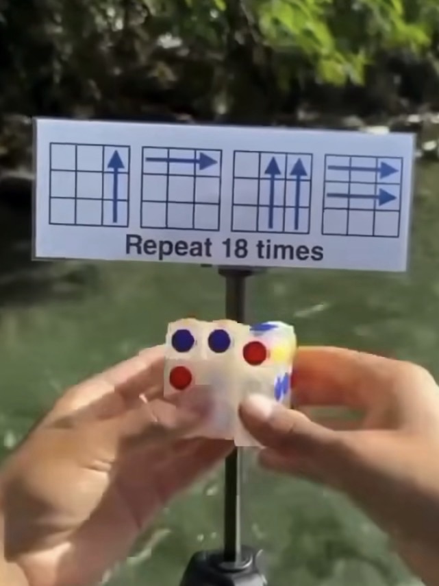
However, as I get older my attention span has expanded slightly, but not to the point that I actually want one. But I have been triggered by a small video I’m seeing online apparently showing how to solve a Rubik’s cube in 18 moves!
But does it really work?
Courtesy of t’internet
If anyone out there actually has one I’d be interested to know your thoughts. Apparently if you repeat the moves shown in the photo above, eighteen times you will have the answer.
If you could instantly master any skill, what would it be and why?
I think I already posses that skill.
And that skill is:
Just minding my own business.
In life we have control over just two things, our thoughts and our own actions. You can’t control whatever anyone else thinks or does, so why waste your time in trying!
Just mind your own business. That’s work a plenty in many cases.
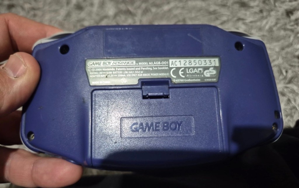
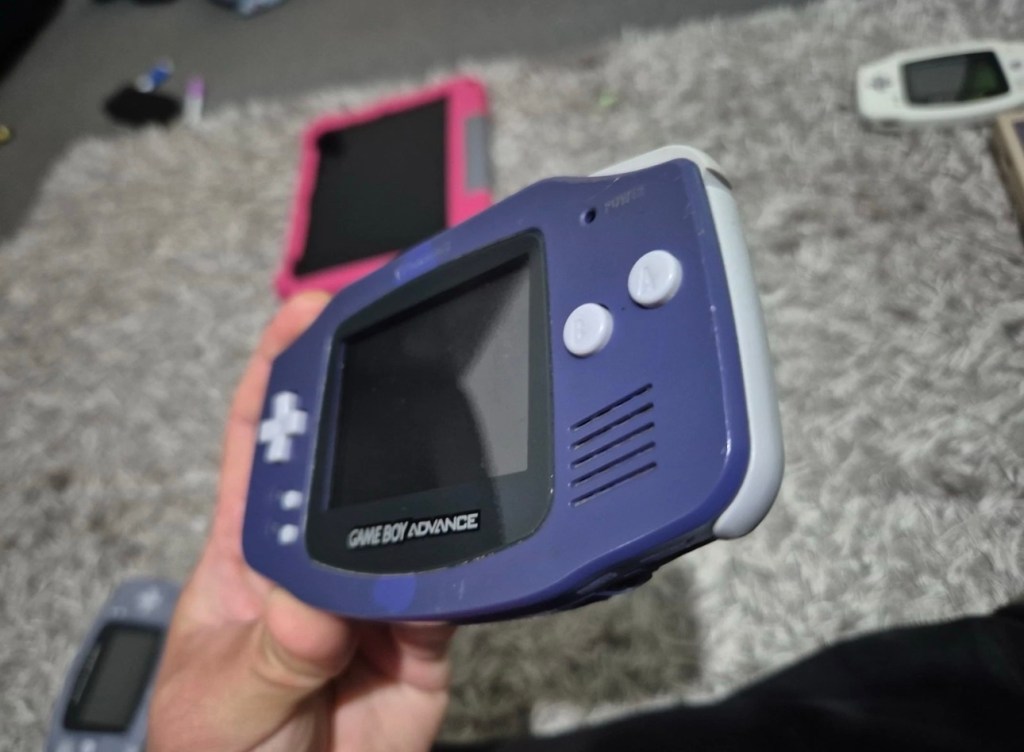
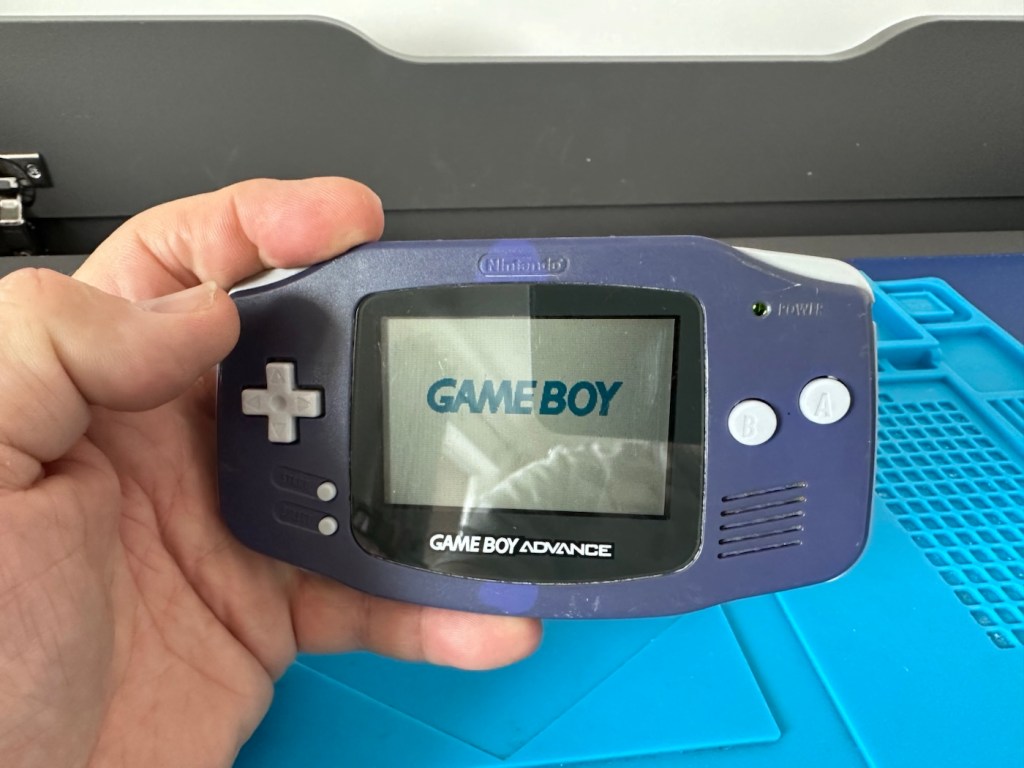
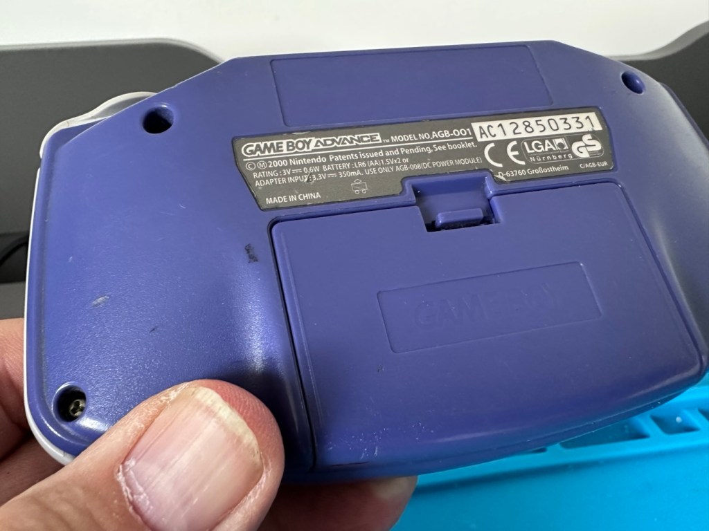
Another one of Nintendos mass produced hand held gaming systems has arrived, with audio issues. It’s a Gameboy Advance, with no sound,so let’s try to fix it.
Here’s what the listing stated:
Gameboy advance console, complete with battery cover, all buttons works and powers on but no sound, has marks on screen and a few marks on shell and scuffs/indentations.
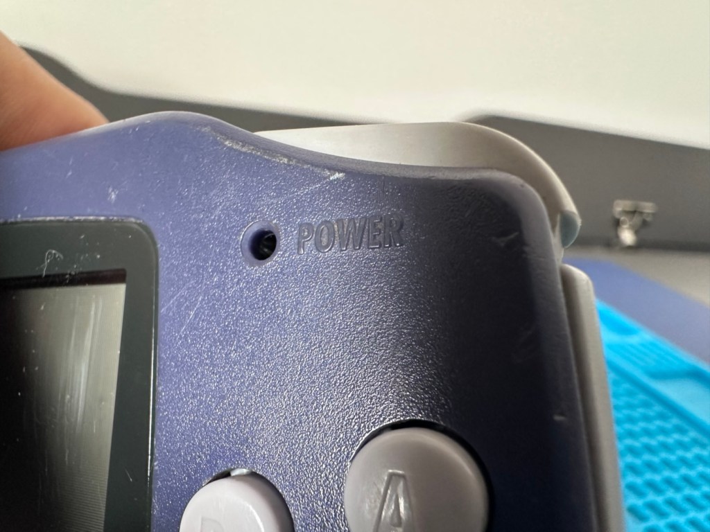
Photos of exact item you will recieve, FAULTY Uk buyers only. Has cover missing that the power light shines through on
EBay
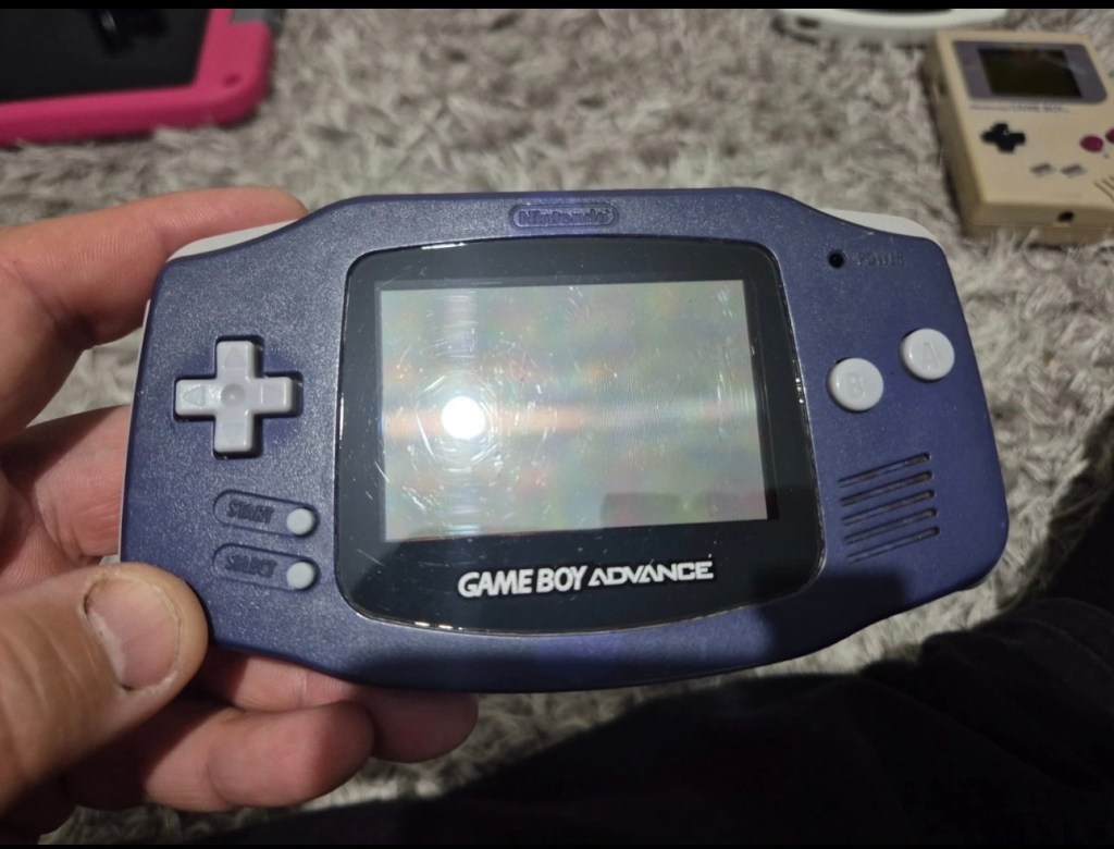
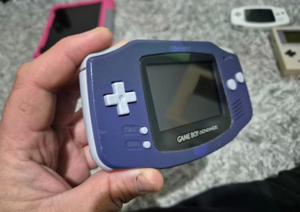
The unit I have purchased
I’ve purchased this as another addition to my collection of handheld retro gaming consoles. As usual it dosen’t work, and that sometimes keeps the cost down a little. This one has cost me £24:00GBP and I’m happy that that is a fair price for one of these units. Here’s a little about the GBA:
The Game Boy Advance(GBA) is a 32-bit handheld game console, manufactured by Nintendo, which was released in Japan on March 21, 2001, and to international markets that June. It was later released in mainland China in 2004, under the name iQue Game Boy Advance. Compared to the Game Boy Color it succeeded, the console offered a significantly more powerful ARM7 processor and improved graphics, while retaining backward compatibility with games initially developed for its predecessor.
The GBA is part of the sixth generation of video game consoles, competing against Nokia’s N-Gageand Bandai’s Japan-only WonderSwan. The original model was followed in 2003 by the Game Boy Advance SP, a redesigned model with a frontlitscreen and clamshell form factor. A newer revisionof the SP with a backlit screen was released in 2005. A miniaturized redesign, the Game Boy Micro, was released in September 2005.
By June 2010, the Game Boy Advance series including revisions, had sold 81.51 million units worldwide, massively outselling its competitors. Its successor, the Nintendo DS, launched in November 2004, was backward compatible with GBA games. GBA sales ended by 2010 after over nine years.
In 2008, the GBA was still Nintendo’s predominant handheld console in terms of market presence and global installed base. It was only in late October 2008 that Nintendo announced that the Nintendo DS had officially surpassed the GBA worldwide in sales. This milestone consolidated the definitive global leadership transition between generations,[13]although in specific markets, such as the United States, the GBA was only surpassed by the Nintendo DS in sales in late 2009.
Wikipedia
Now just to reiterate. These units are now 25 years old, there were in excess of 81 Million of these units produced and they still command a good price today. Just consider how many of those units have been sent back into landfill, the figure is probably immense. But then again we produce many items en masse, and we have been just chucking stuff away for years. The figures must be mad.
Except for this one. It will be repaired, cherished and reused. And displayed for all to see.
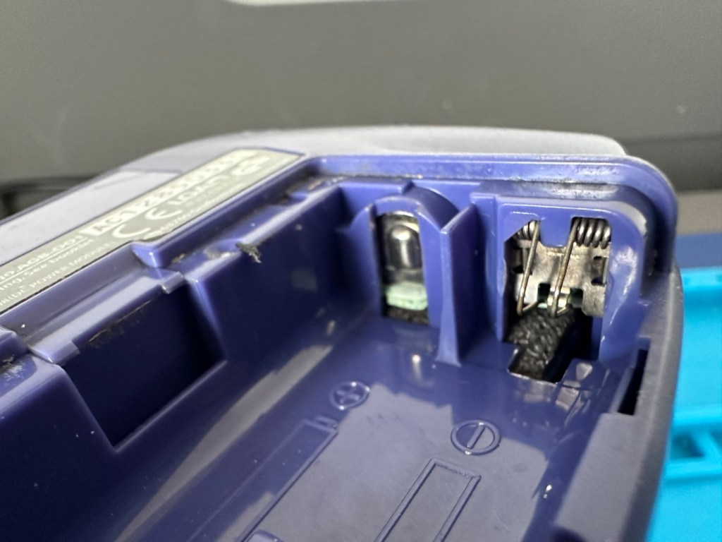
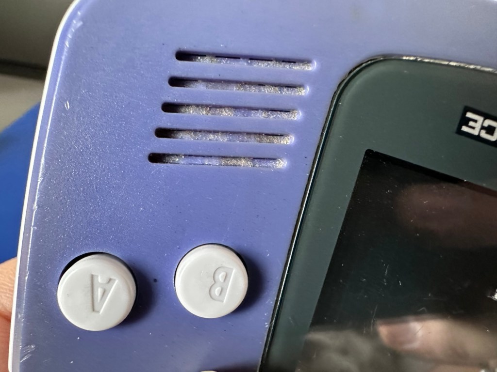
This one has been advertised as having no sound. Just from viewing the sellers photos you can see there is an awful lot of staining around the speaker grill area, maybe some liquid has been spilled here and the speaker is damaged, or maybe the audio capacitor inside has blown. These are usually the two main culprits, but you never know it could be for some other totally different reason. Let’s not make assumptions, let’s see what turns up.
Assessment:
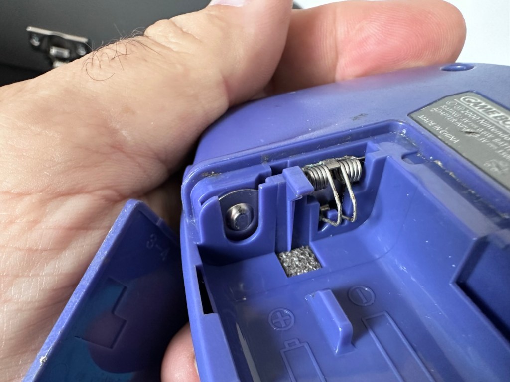
The unit has arrived all in one piece. The battery cover is in place, a little loose at the clip but I might be able to strengthen by heating and gently manipulating it.
It works but no soundBattery cover Clean contactsClean but a bit grubbyConnection ok, needs a cleanNo sound, dirtyNo light lensLight scratches
Battery contacts show no sign of corrosion but are a little grubby. There are signs of good use but nothing really bad to be honest, all connectors and buttons appear to be doing what they should. The unit is in good need of a thorough clean, as it does look a little worn in that aspect. Screen has very minor scratches, nothing that will cause any issues. The little acrylic lens by the power light is missing and there is as stated, no sound even though we do have a picture and are able to play the games. In all aspects the unit is functioning, just with no audio.
This is a fair unit, it will clean up and if we can get the audio working we have a potentially very good unit.
It is dirty though, and a good clean will make an immense difference.
Repair:
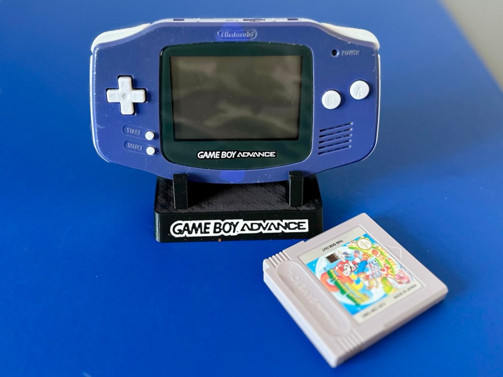
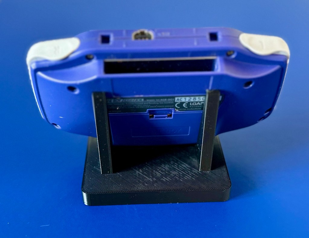
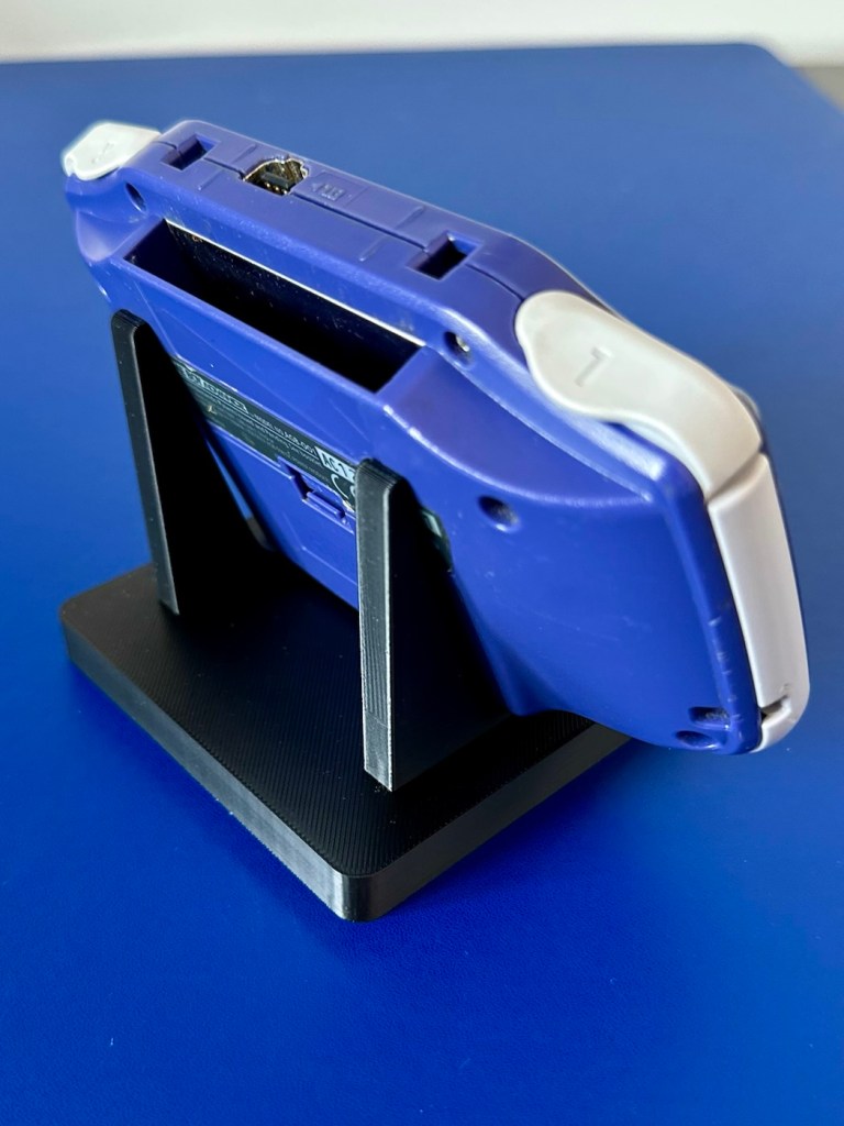
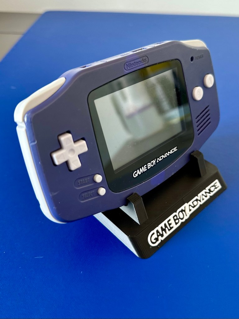
The printer is on and warmed up so before we get repairing, let’s print a suitable display stand for this unit.
Display stand printing
Now let’s open up the unit and see what we have inside.
First there are seven tri wing screws securing the shell. Remove these and the rear of the unit just lifts off.
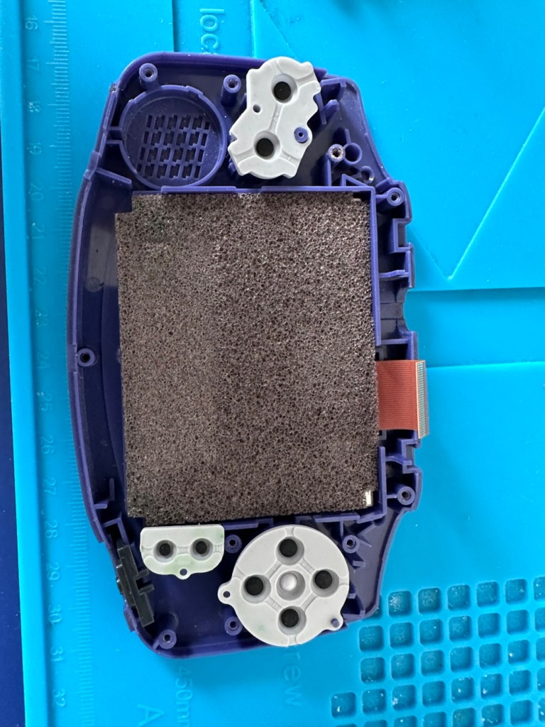
Seven screwsRear removed. Board missing two screws
Next there should be three screws to remove the mainboard but there is only one. Someone has previously been in this unit and has left two screws out. Next we remove the ribbon cable that secures the screen to the mainboard.
Remove ribbon cableScreen and front of the casing put to one side
We now have free access to both sides of the board and can put everything else to one side to start our fault finding process.
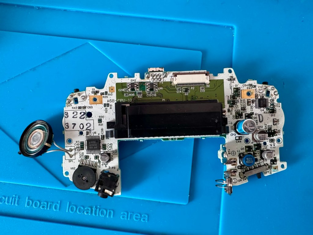
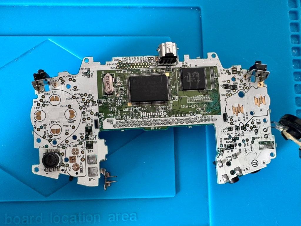
Rear of boardFront of board
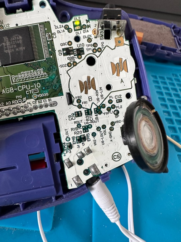
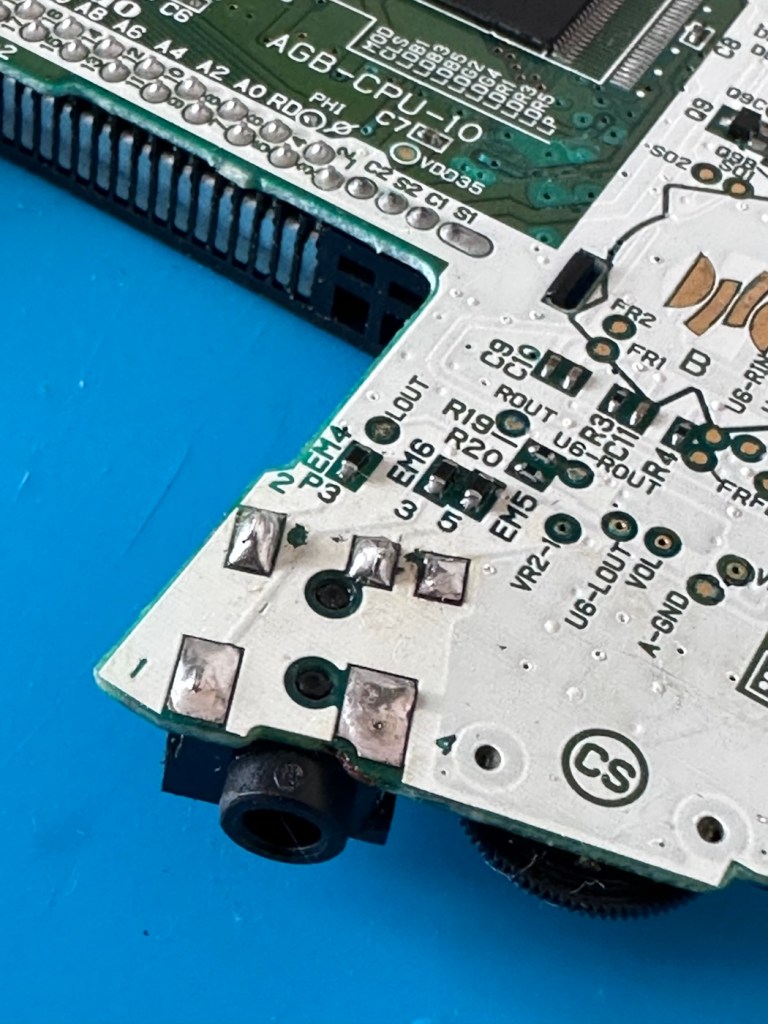
First things first, let’s check the speaker. With the multimeter it’s showing 8 Ohms so I’m happy that the speaker is ok. A quick check for shorts and not one capacitor shows a short, I plug in a set of headphones and I can hear sound, but as soon as they are unplugged there is no sound again. My attention is now at the earphone socket.
ContaminationHeadphones plugged in
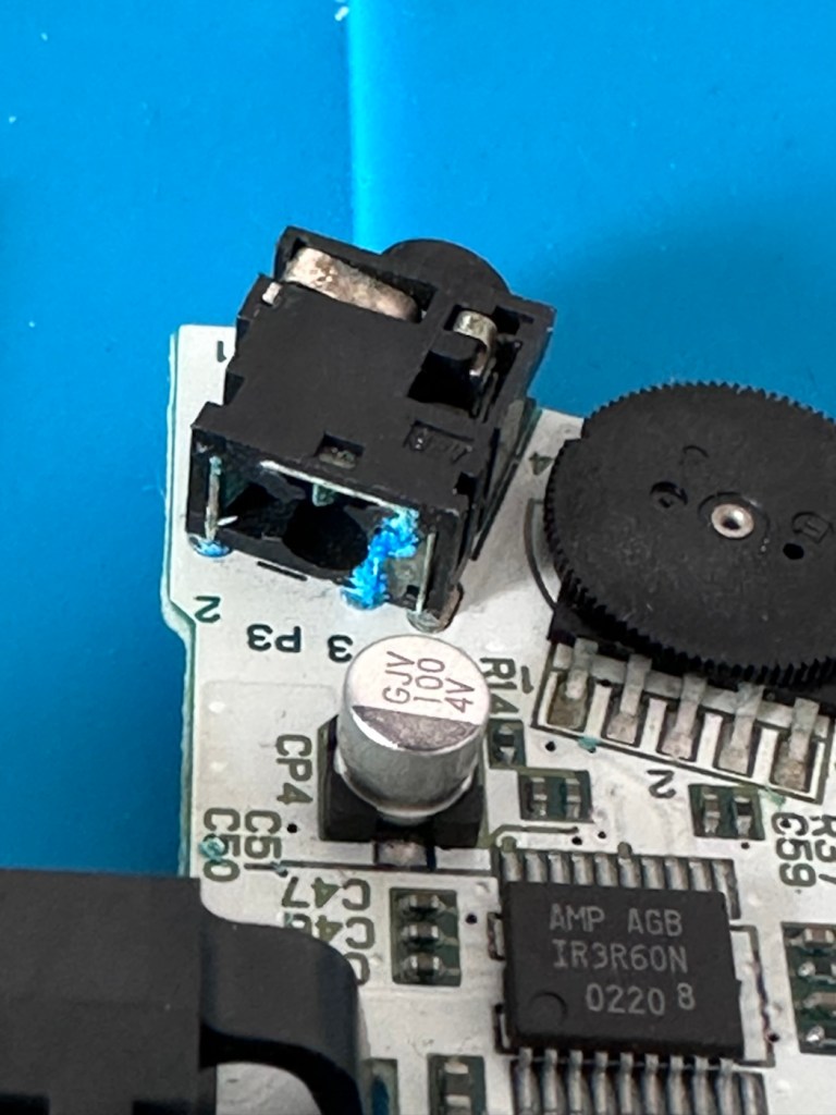
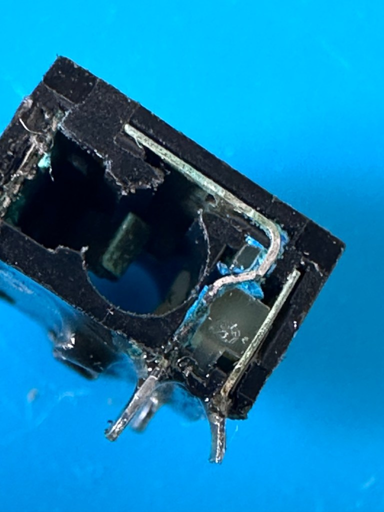
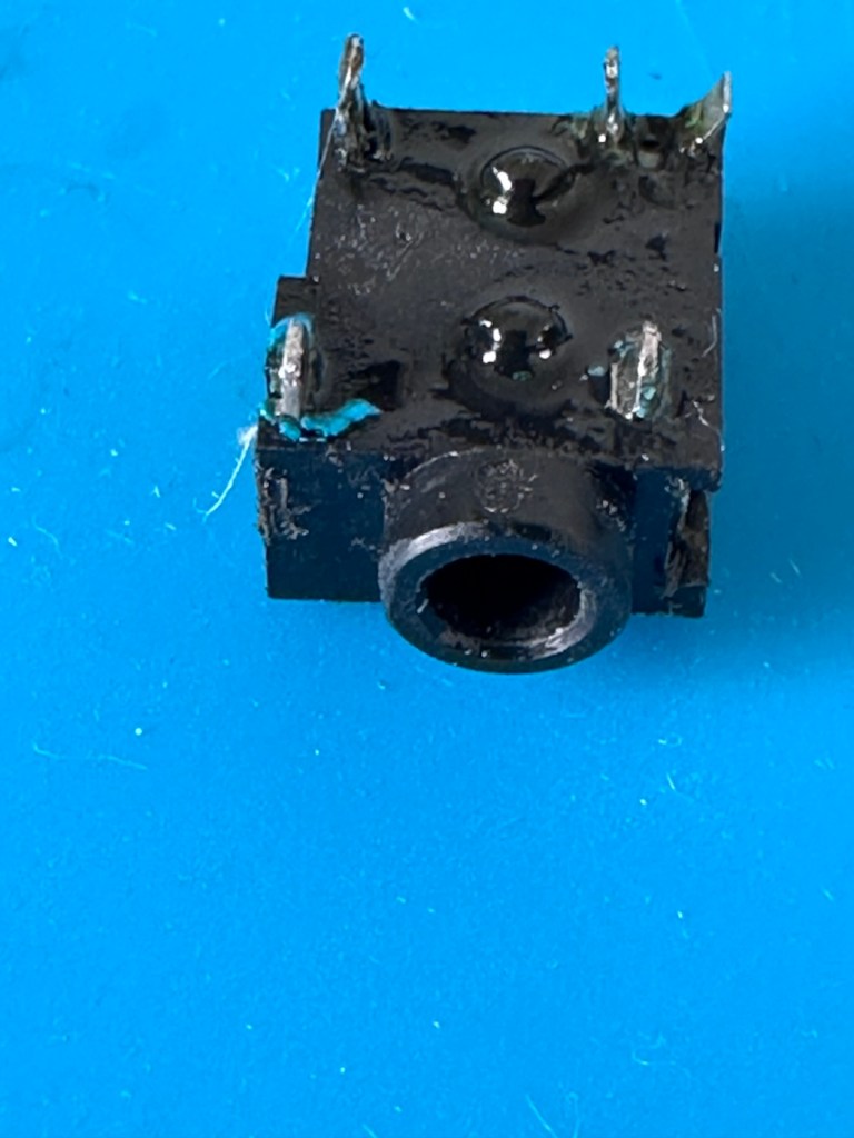
On close examination other is a considerable amount of battery acid contamination in the earphone module. This is strange as there is none evident in the battery contact area. A close look around shows some spots of contamination, however these are easily cleaned with some IPA. I have a feeling this may have been a previous issue and the person in here prior to me, has cleaned up, but given up on the repair.
I remove the earphone module, and clean the surrounding area.
Front Rear Contaminated See the blue contaminants
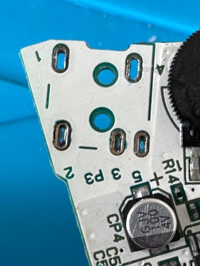
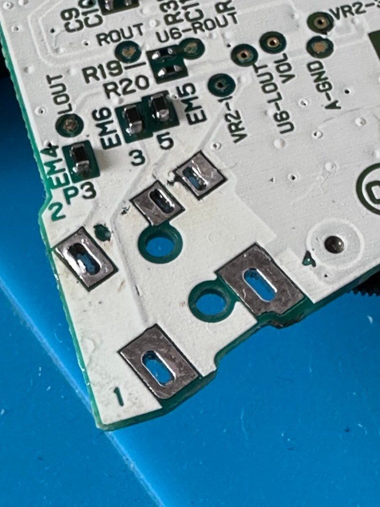
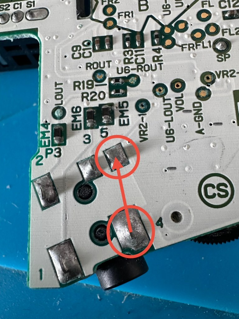
A simple check here is to see if there is any continuity between the two tabs that occupied positions 4 & 5 as marked on the mainboard. This check is carried out on the actual module. If you have continuity between these two pins, then in theory the circuit is good, and the speaker should be working. My results here were negative as there was no continuity on this module between those points.
The way the earphone works is thus. Plug the earphone jack in, it opens up the contacts and by passes the external speaker. Remove the earphone jack and the contacts close, opening up the main speaker. If there are contaminants on the contacts, this can prevent continuity and hence there is no sound on the main speaker.
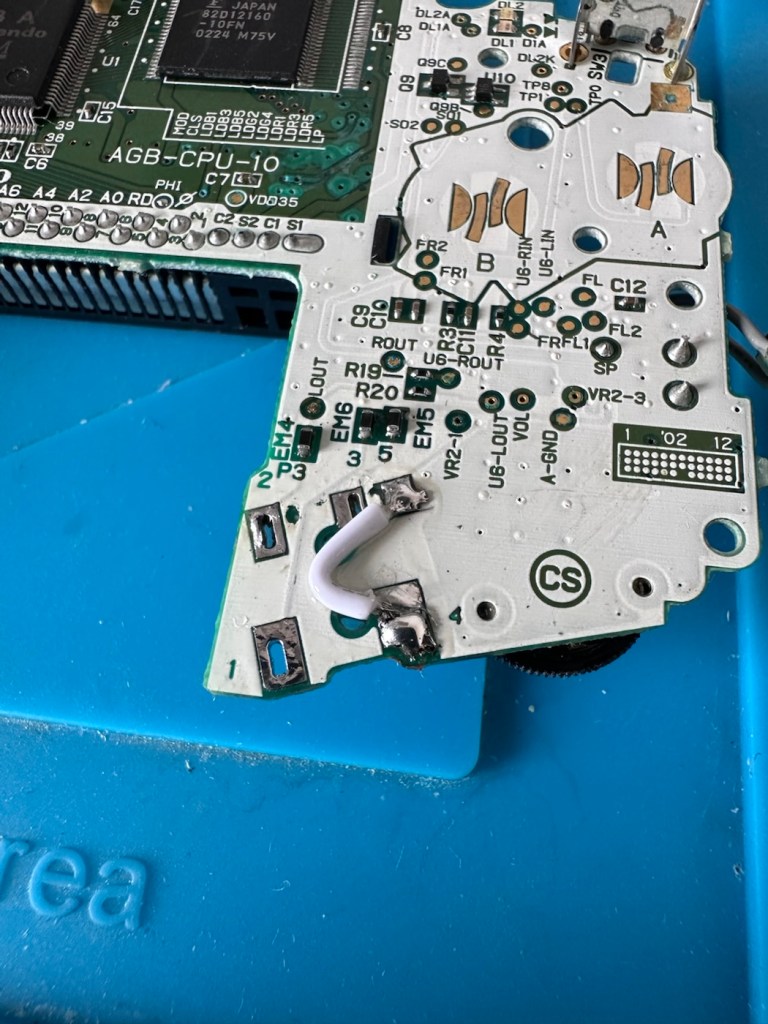
You can double check that this is the issue by soldering a small wire between points 4 & 5 on the mainboard in theory by passing the earphone circuit leaving the speaker circuit open and accessible.
Short these two pointsShorted with a small wire
And my suspicions were correct, this small video below was the result of bypassing this part of the circuit.
We have sound in the speaker
Looking inside the earphone socket it was easy to see this piece had a solid lump of contamination exactly where I was expecting to see it. I have no spares of these and to obtain one off of the auction sites is an absolute ripoff. I can order one from our friends in China but I’m looking at a four week turnaround here, and I’m inpatient and not willing to wait that long. I’m going to try and repair it.
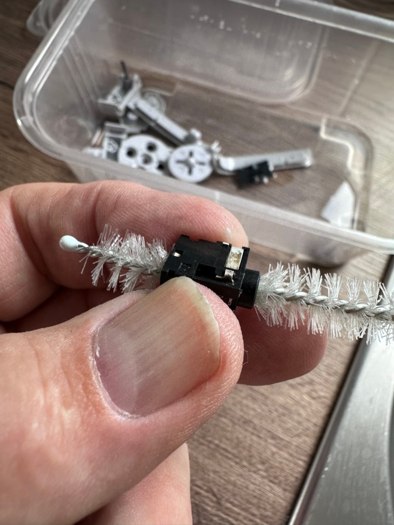
I’ve gathered everything up that needs cleaning, buttons, connectors, screws, pads and the suspect connector, and dropped the lot into a small dish of white vinegar. White vinegar is great for removing contaminants and you can actually watch it fizzing away and working. I left these items bathing for about 30 minutes before giving them all a good scrub clean. On the earphone jack I “borrowed” a small bottle cleaner from the wife, it fits right through one side and out the other allowing you to get a really good scrub inside.
White vinegar and a bottle scrubber
I also cleaned the outside thoroughly removing all signs of contamination, the tabs were gleaming when I finished. I then put everything I’d just cleaned in between two sheets of kitchen roll and put them in a cooling oven to dry off.
When dry I took the bottle cleaner again, inserted it back into the earphone jack, sprayed quite a bit of electrical contact cleaner back onto it and vigorously scrubbed again for the next few minutes. When dry, I took the multimeter and again checked for continuity across points 4 & 5 and a tone was heard. Continuity had been restored and the earphone contacts were now working. Plugging in a jack and then removing it confirmed that all was working as it should. It’s now time to put this jack back on the board.
Earphone port, back in place
Final touch is to put a tiny pice of clear silicon in place of the missing power light lens on the front of the case. Job done.
Time to reassemble this unit.
Result:
And here we are. The original unit has been thoroughly cleaned, it’s come up ok but is probably a good candidate for a case upgrade and a Capacitor change at some point. That’s just cosmetic though, what really matters is that this unit is now working perfectly, and it sounds just fine.
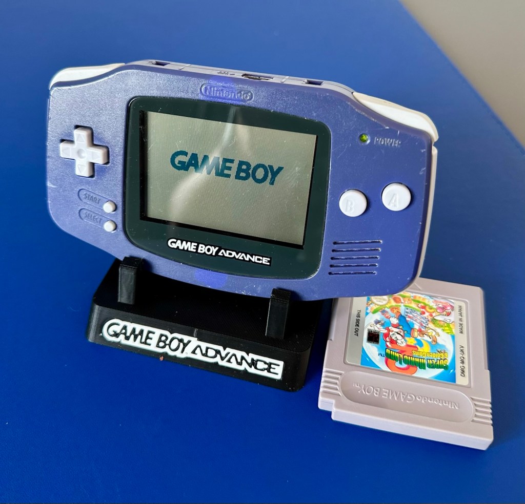
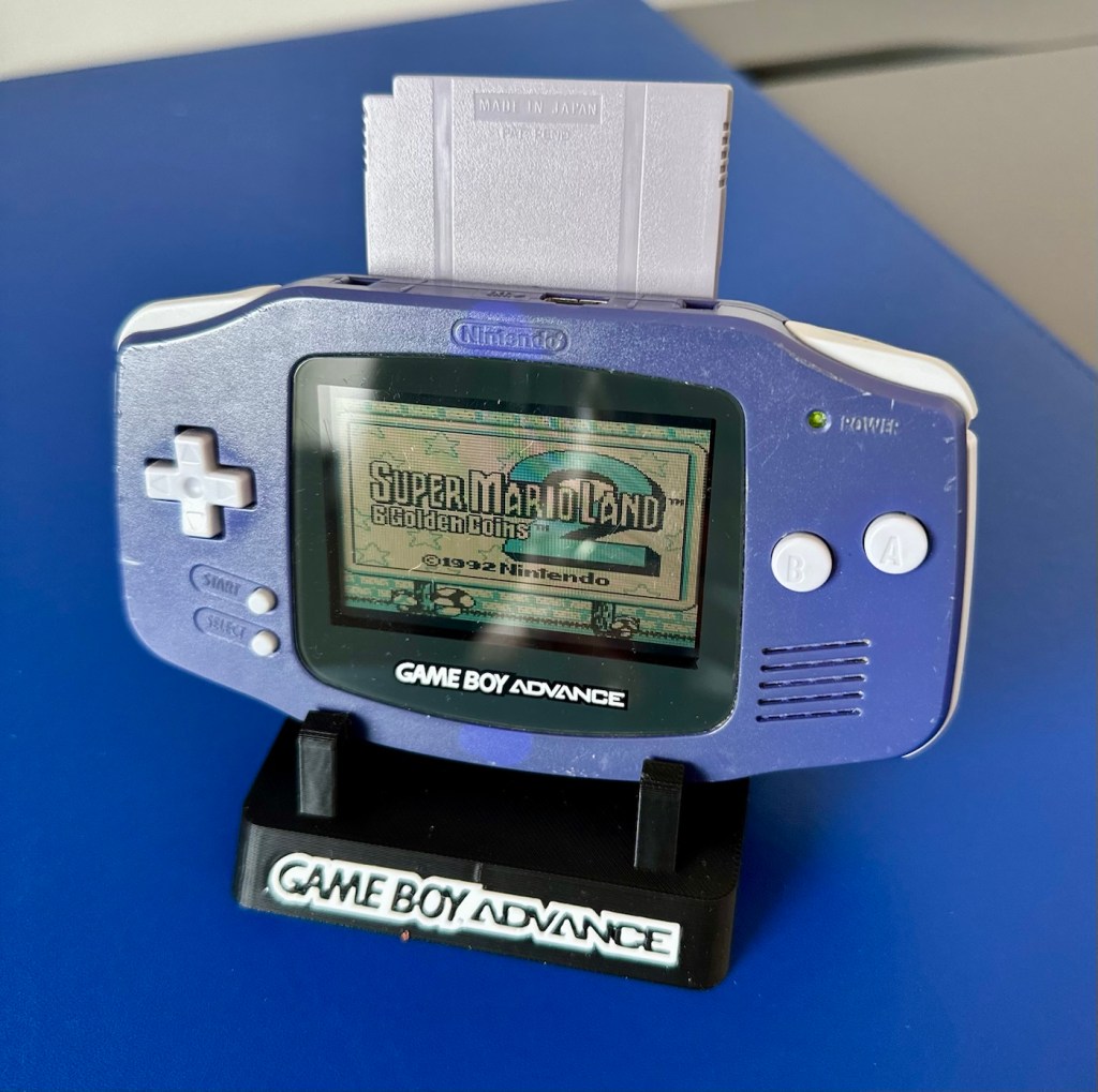
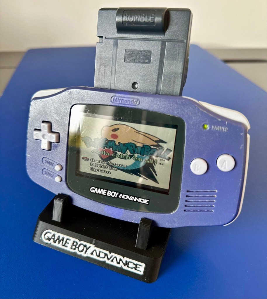
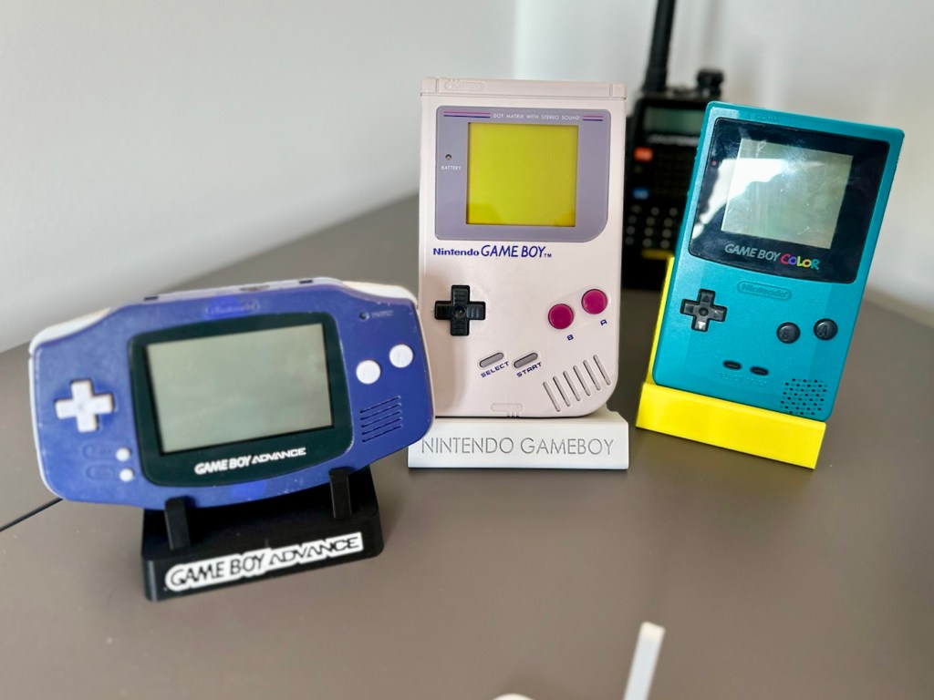
Fixed, cleaned, on its new stand with its fellow Gameboy counterparts
This unit actually came from a guy who restores these units, I guess he was just having an off day as to be honest, it wasn’t the most difficult issue to diagnose and repair. It honestly took longer to clean this unit than it did to repair it. I’m pleased that I’ve used all the original parts and just been able to do a proper restoration as such.
81 million of these units were produced, so this is just one in that 81 million, that has been saved again from landfill to be enjoyed for many more years to come.
I’ve purchased a faulty Gameboy Color for my collection. It has no power, so let’s have a look and try to get it working again.
What the listing stated:
Very clean, but doesn’t turn on
EBay
Gameboy Color
Yep. It’s a Gameboy Colour to me, but as it was sold using the American spelling of “Color” then that’s what it will be addressed as, going forward.
I’ve been after a “Color” to add to my collection for a while now, but it had to fit my very strict quality requirements, in truth it just has to be faulty, and this particular example has met my conditions. I’ve paid £30.00GBP for this example and I’m happy with that, it’s a very fair price.
The good news seems to be that it is in a really good condition, it looks as if the battery door is missing, however they are freely available and this is not an issue should I require one.
These units are known to sustain power failures and the repairs are well documented. By now the unit is close to 30 years old and as time advances components start to fail, these include, but are not limited to:
Power switch failure: either a complete failure that requires replacement or quite simply a simple clean to remove years of tarnish and environmental gunk.
Fuse failure: there are two fuses F1&F2 that are known to fail, normally due to a short somewhere else on the circuit, but sometimes due to a power surge or incorrect addition of an incorrect power supply.
Via failure, small through the board connectors that are known to suffer with corrosion, requiring intervention with the addition of small wires to bypass the issue.
Capacitors – known to fail on a regular basis, it’s sometimes good housekeeping just to get these replaced as they are a contributing factor as to why other components such as the fuses also fail.
Worst case scenario: major corrosion or main board component failure.
We’ll cross these bridges when and if we need to.
Here’s a little info about the Gameboy Color console:
The Game Boy Color(abbreviated as CGB or GBC) is an 8-bit handheld game console developed by Nintendo. It was released in Japan on October 21, 1998, and in international markets the following month. Compared with the original Game Boy, the Game Boy Color features a color TFT screen instead of monochrome, a CPU running at up to twice the speed, and four times as much memory. It is backward compatible with games developed for its predecessor. The Game Boy Color was released during the fifth generation of video game consoles and competed with Bandai’s Japan-only WonderSwan, SNK’s Neo Geo Pocket Color, and Sega’s North America-only Genesis Nomad.
The handheld is slightly thicker, taller and has a smaller screen than its immediate predecessor, the Game Boy Pocket, but is significantly smaller than the original Game Boy. As with its predecessors, the Game Boy Color has a custom 8-bit processor made by Sharp. The American English spelling of the system’s name, Game Boy Color, remains consistent throughout the world.
Wikipedia
So, for now, let’s not speculate on its quality and issues until it arrives, when we can then carry out a proper assessment of the unit that has been received.
Assessment:
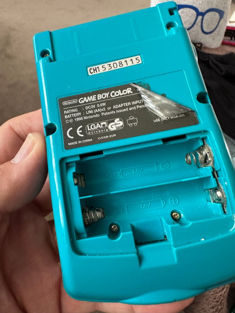
The package has arrived. The battery lid is missing as kind of expected, I will get a replacement sometime, but for the moment I’ll probably print one out on the 3D printer, it’ll be a totally different colour as I don’t have a “Teal” coloured filament to use. The product label on the rear is also damaged but I can easily get one of these as a replacement, however it’s not essential and will only be of cosmetic appeal.
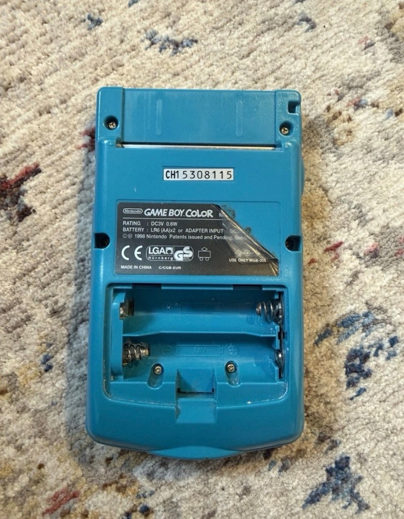
Missing battery cover and old product label
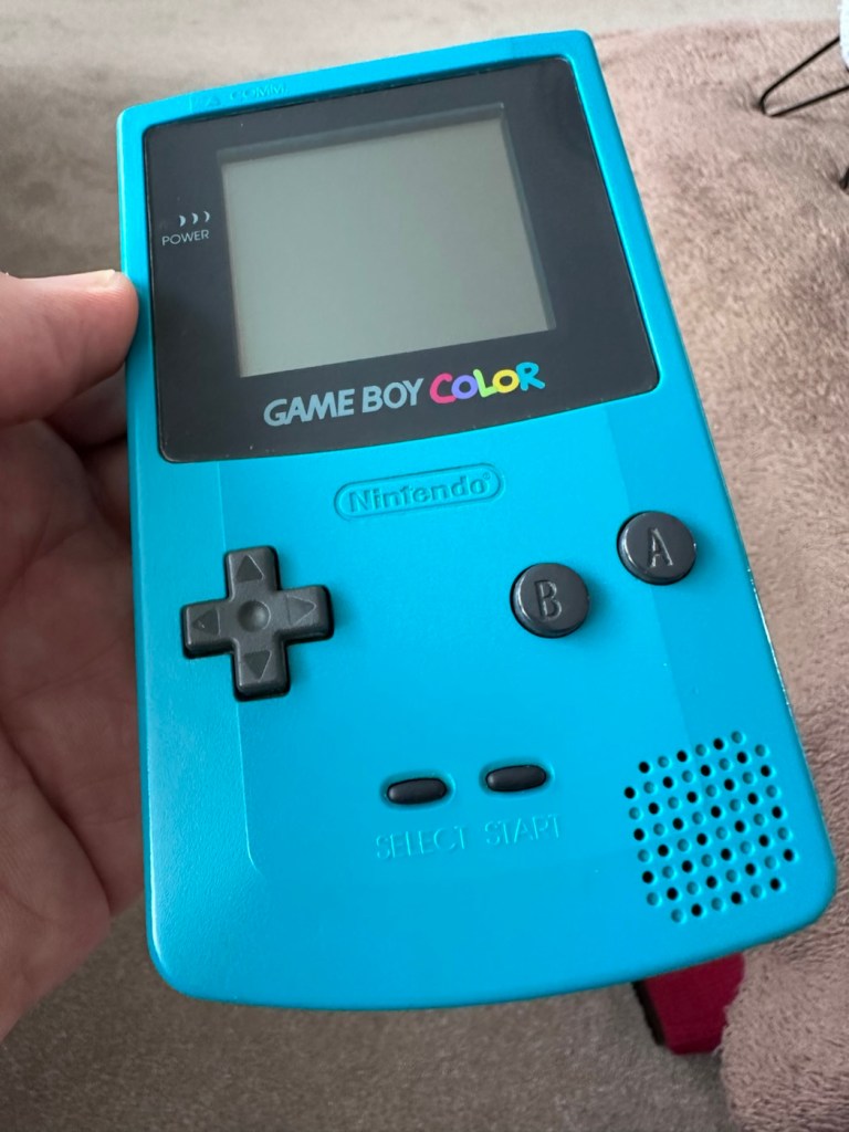
The front fascia is in a good condition with only a minor scratch on the screen, however there are a couple of dents and dinks on the body where it looks as if it’s been dropped or bashed at some point.
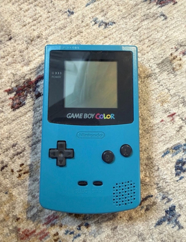
Front fascia is good
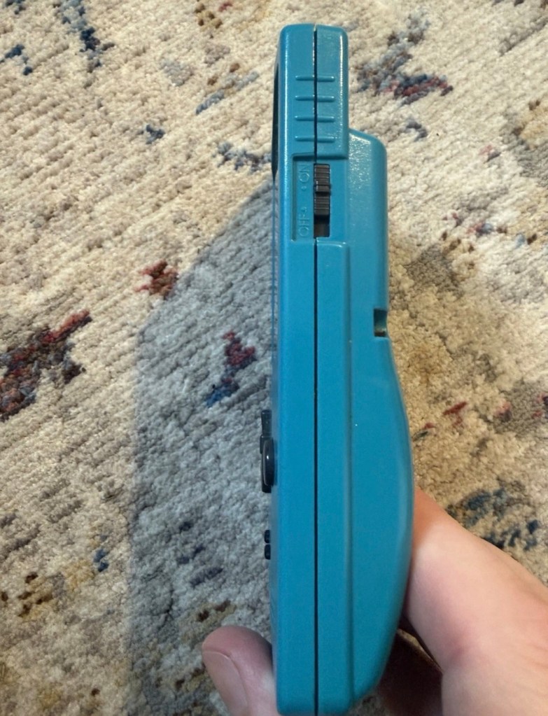
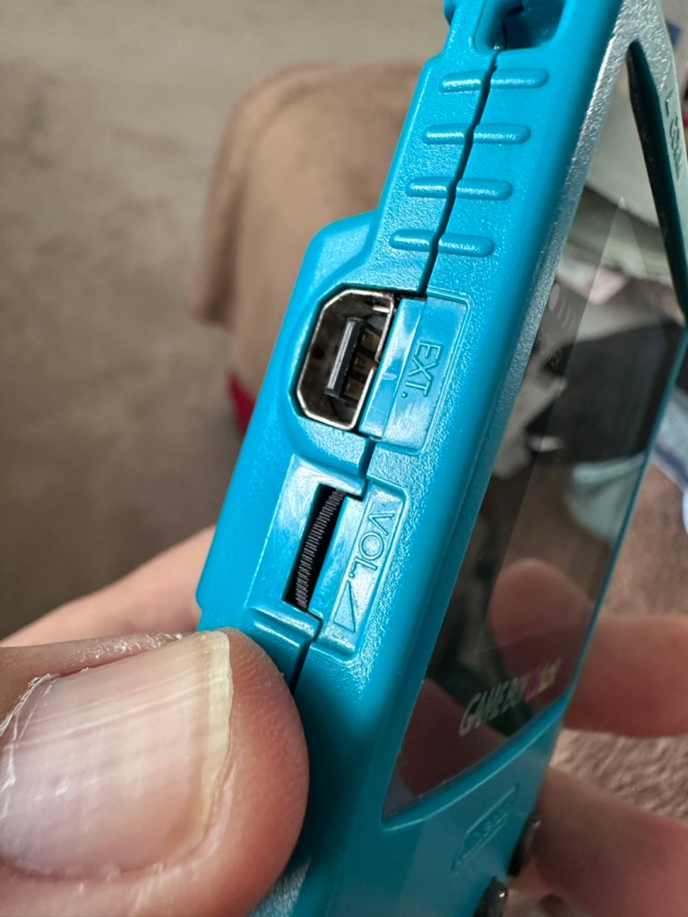
All ports, switches, buttons and sockets look ok and seem to be operating as such with no resistance or signs of stickiness.
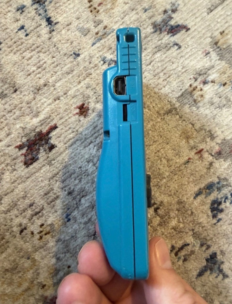
All ports appear ok, there are a few dents and bashes visible
Again, the casing is in general fit to use, and in no way causes any issues with its operation when working. It is purely a cosmetic issue that i can address when the unit is finally working.
I have installed two AA size batteries, switched the unit on and it is most definitely dead. Repeatedly flicking the switch does nothing at all, so it is a situation where the unit will have to be opened up and further investigated. The assessment has not thrown up any other issues not already highlighted in the sales documentation, so in general I am quite happy with the outcome at this stage. let’s get inside and see what we can find.
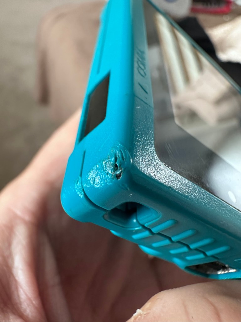
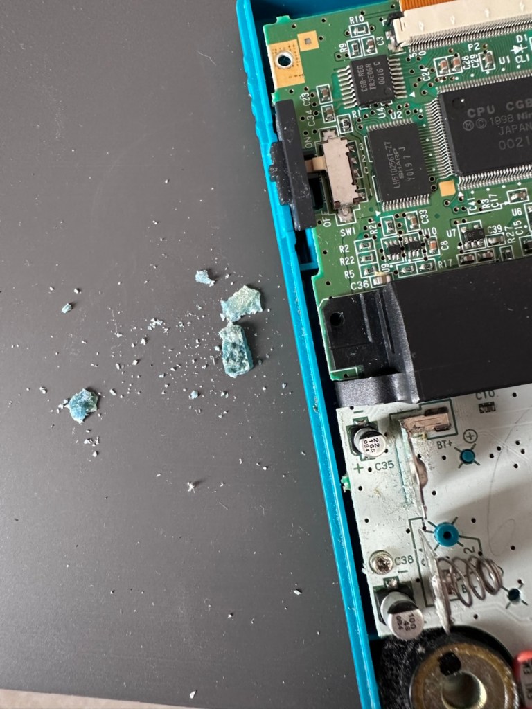
Oops. Wasn’t expecting that. I’ve removed the six “tri” screws and as soon as I’ve separated the two halves, an amount of what looks like battery corrosion “crap” has fallen out as well.
Oops – corrosion is present
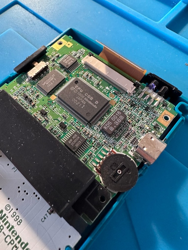
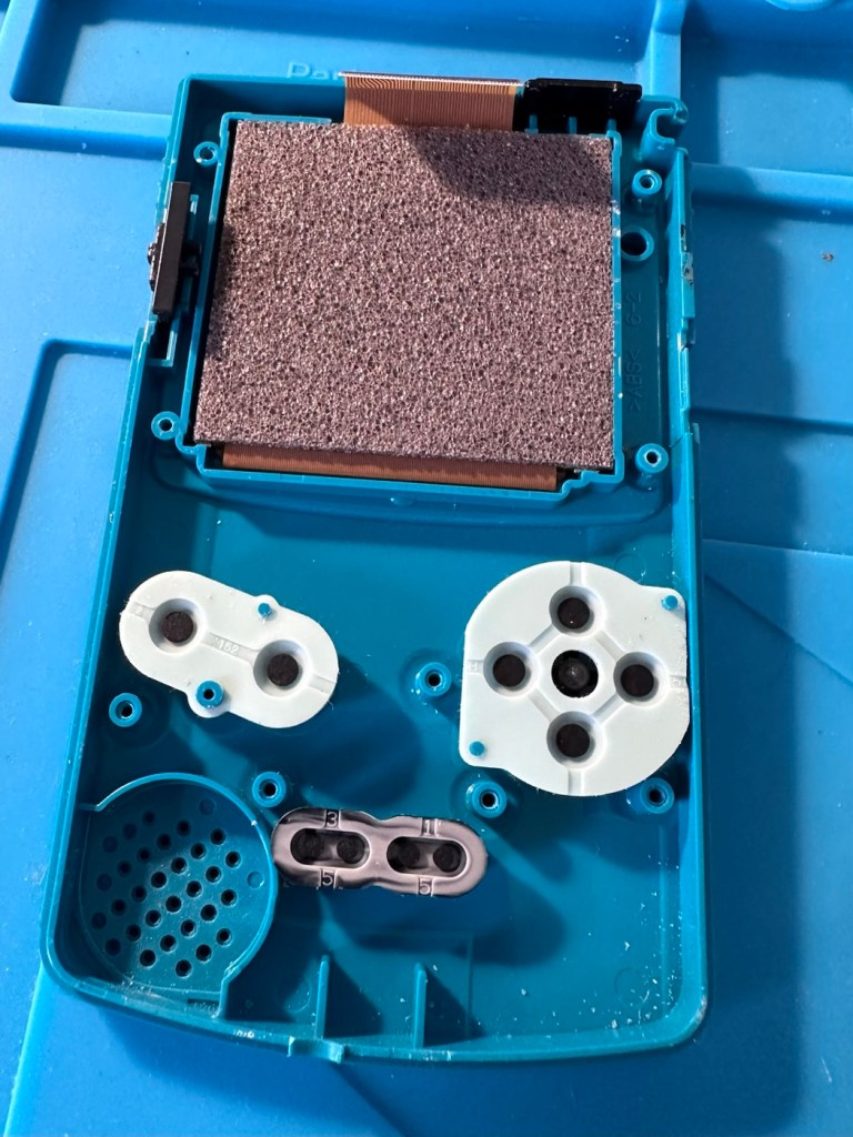
With the two halves separated, I then remove the screen ribbon cable, remove three more screws and the main board lifts out.
Screen ribbon cable removalInside upper part of the unit
There’s some good news here. The contamination looks as if it has been completely isolated to within the battery area, there is no sign of any damage to the Vias, or any other components on the main board.
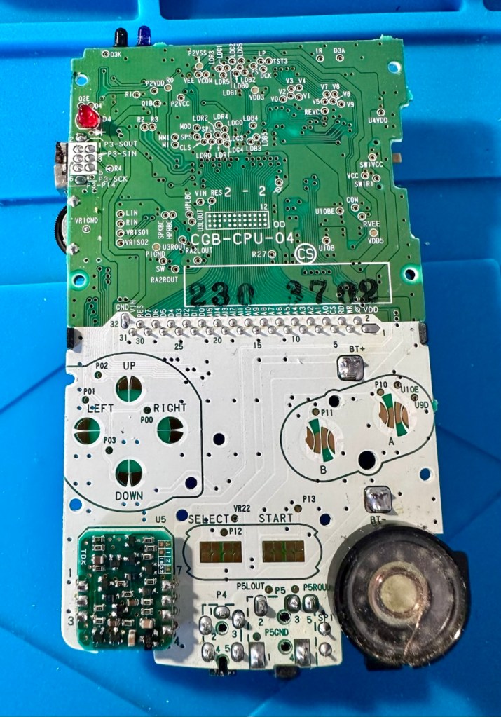
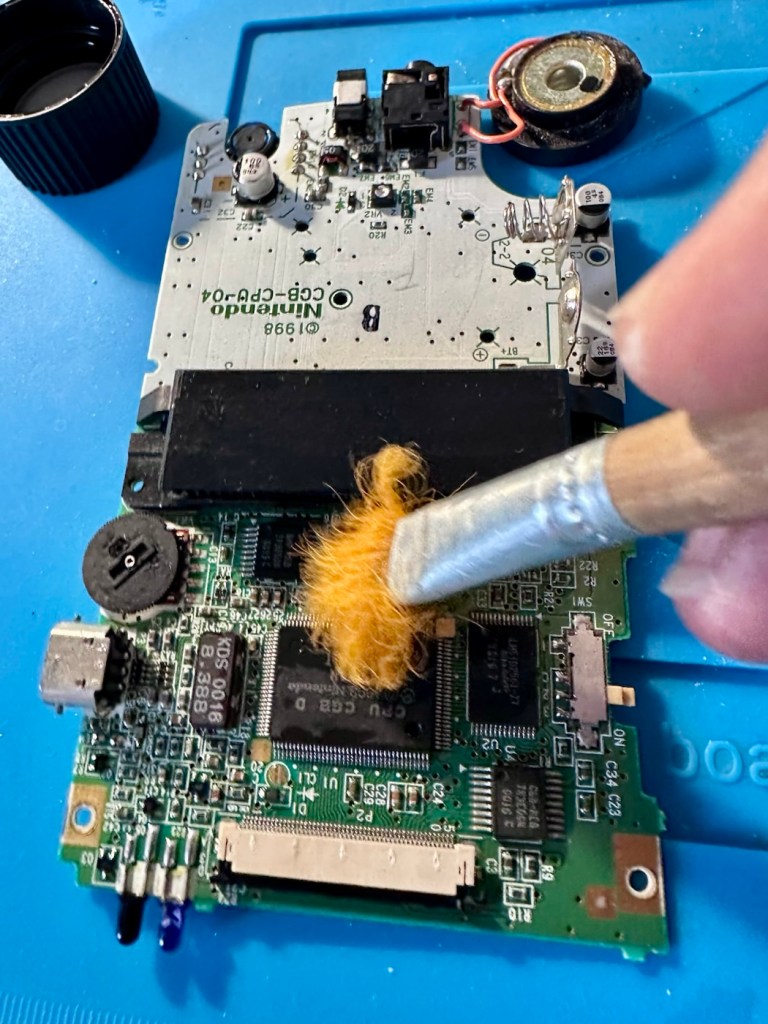
Main board on both sides, cleaned with IPA
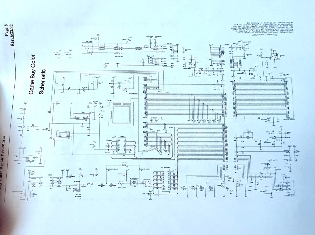
I have obtained the schematic diagram for this circuit board for checking continuity, and i’ve been able to confirm there are no issues with any contamination damaging any traces to the board. We’ve been very lucky here, dodged a bullet, to coin a phrase.
Schematic diagram
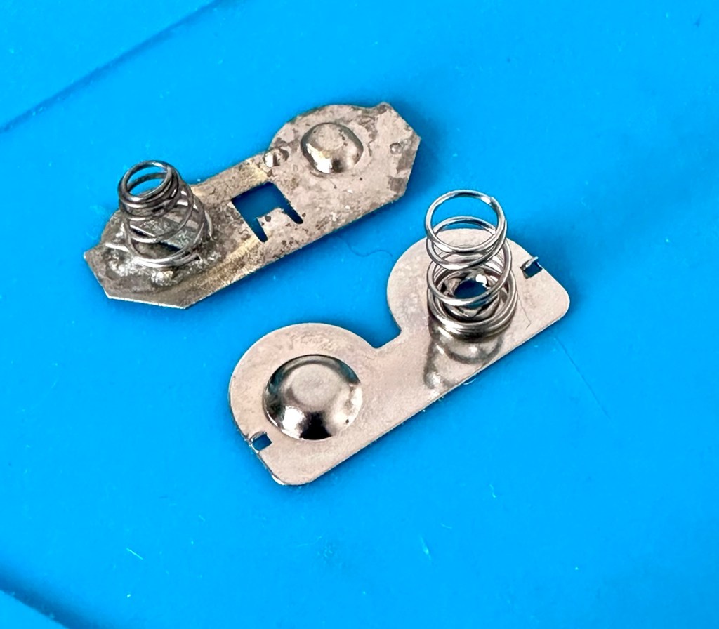
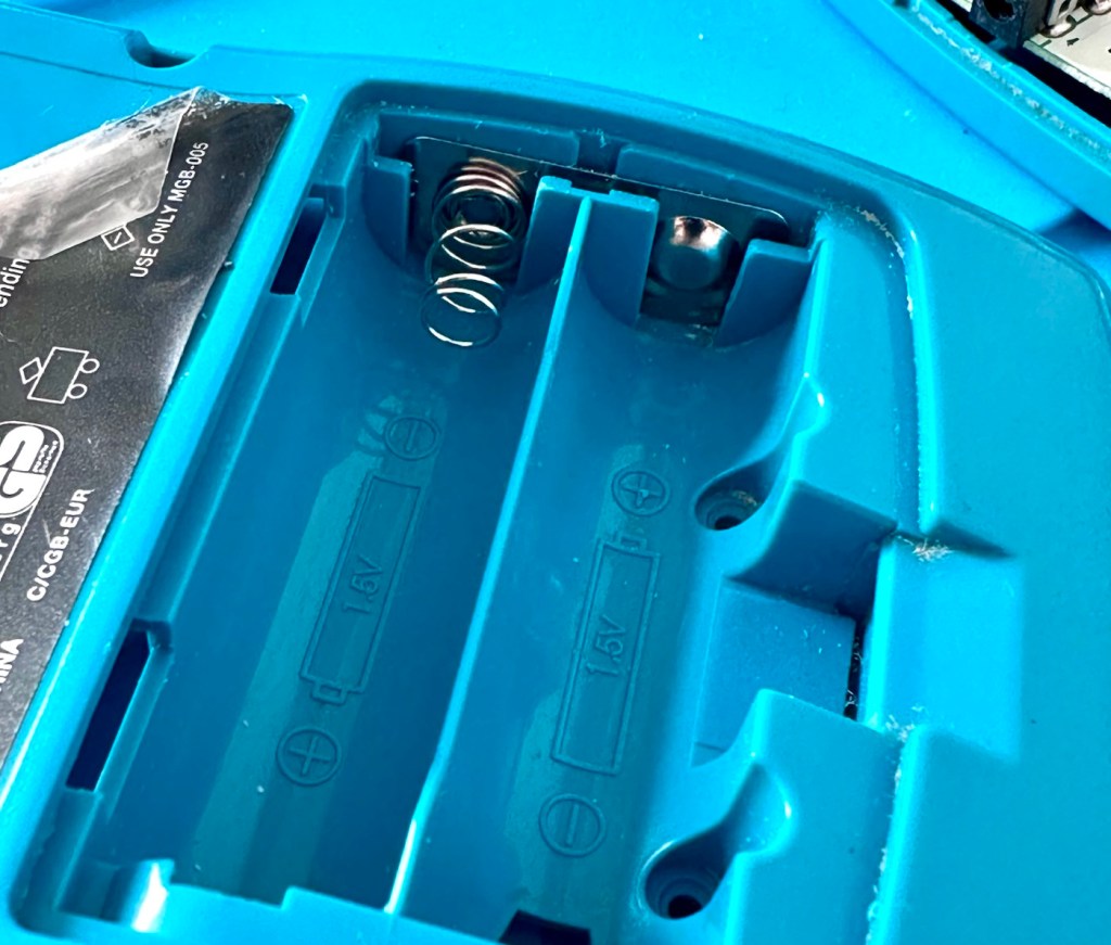
I have removed a set of battery contacts from the battery area, and replaced these with a new set that I have in my spares box. I could clean these, but it’s good to remove all items that were originally contaminated and very possibly contributory to the fault we have today.
Old and new contactsNew contacts in place
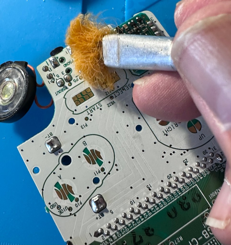
I have also cleaned the front and rear of the main board with IPA just to ensure that if there was any issues with contaminants on the board, they’ve now been removed.
The switch has been tested electrically with a multimeter and this is working fine. The three capacitors have been looked over and seem to show no signs of wear or deterioration, they haven’t been properly tested though, so let’s now check fuses F1 & F2.
For reference: Fuse F2 protects the DC jack, whilst F1 protects the battery compartment. Using the continuity mode on the multimeter, a continuity through the fuse should present an audible buzz that let us know the fuse is complete and has not failed in any way.
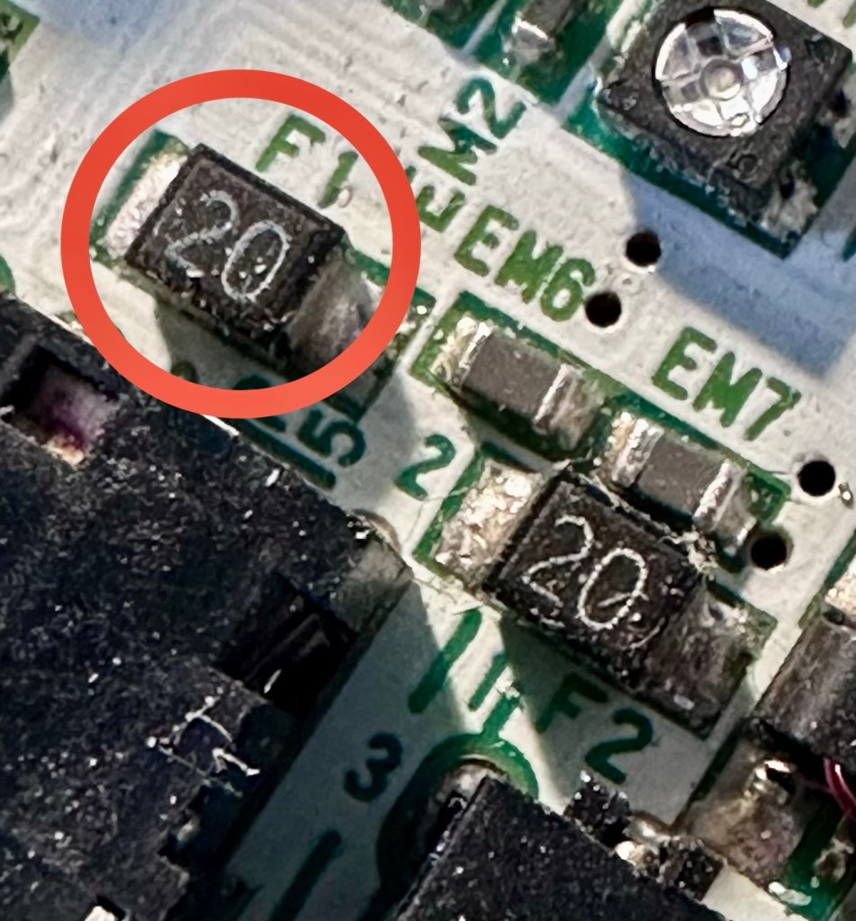
I start on F2 and get a healthy buzz that tells me F2 is working fine. However fuse F1 is a different story, there is no continuity and there is no sound, I check again and can confirm that this fuse has blown, maybe this is a result of the contamination that was in the battery area?
The two fuses, F1 is dead
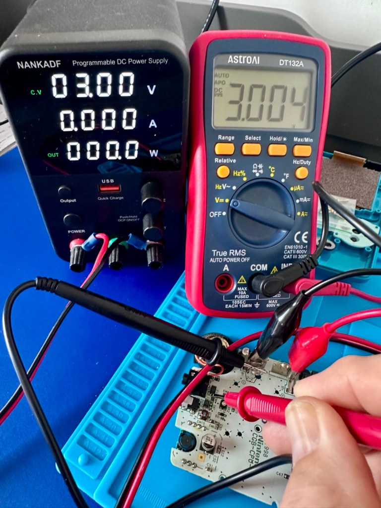
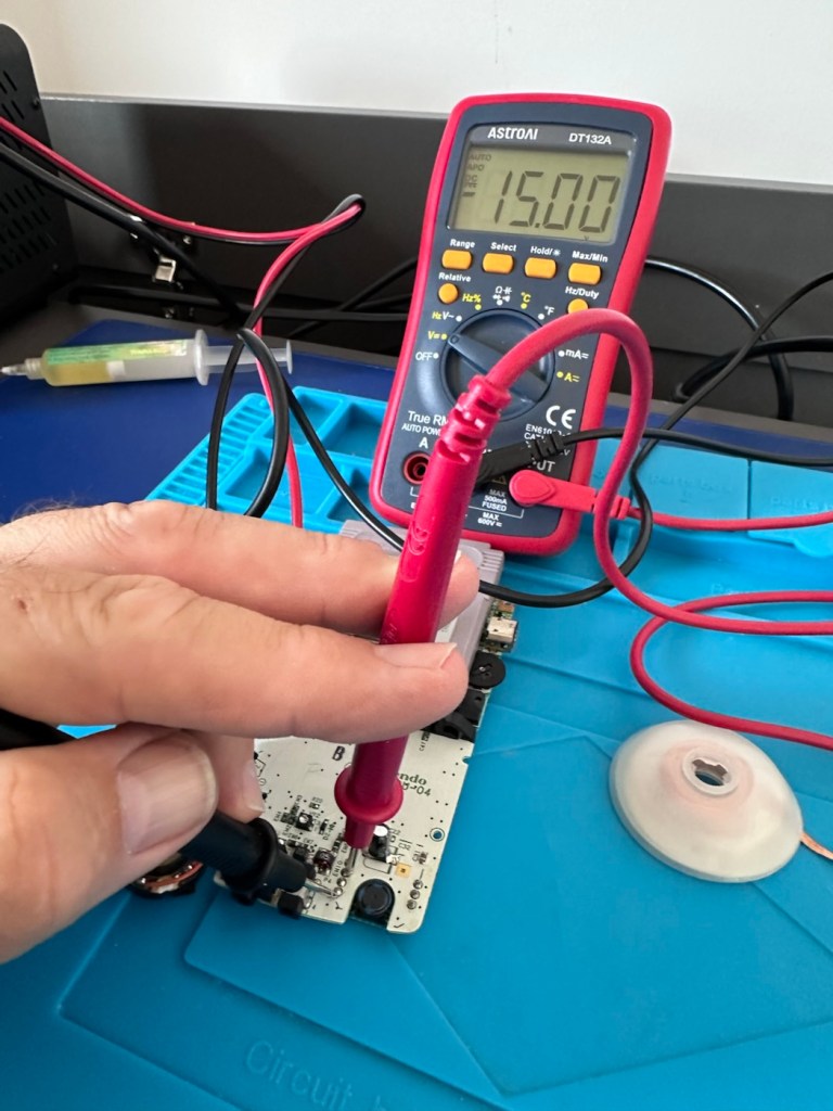
I’ve now attached the bench power supply supplying a 3v input to clarify the fault.
A 3v supply proves the fault
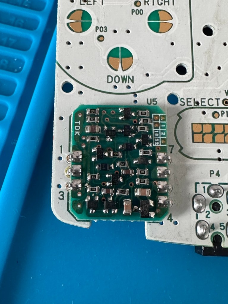
Fuse F2 has a 3v supply on each side, however our suspect fuse F1 only has a 3v supply on one side confirming that this fuse has blown. Once this fuse has been replaced I can check the voltage supplies on the remainder of the board, especially on the DC-DC regulator board, that supplies varying voltages from 3v – 13.6v required around the main board. On the main board the voltage regulator can be recognised as U5.
DC-DC voltage regulator U5
A quick check for short circuits doesn’t show anything of concern, maybe when the fuse is replaced it may well open up some other issues, the fuses I will be using are “resettable” fuses. These fuses seem to be the standard now for these units. Most resettable fuses—known as Polymeric Positive Temperature Coefficient (PPTC) or polyswitches—reset automatically and do not have a physical reset button. Once the underlying overcurrent or fault condition is removed, you simply disconnect the power source to allow the fuse to cool down, then you switch on again, if the same issue occurs, there is an obvious issue present that needs investigation, as stated above, once the faulty fuse is replaced I will be able to check other areas on the mainboard for correct voltages.
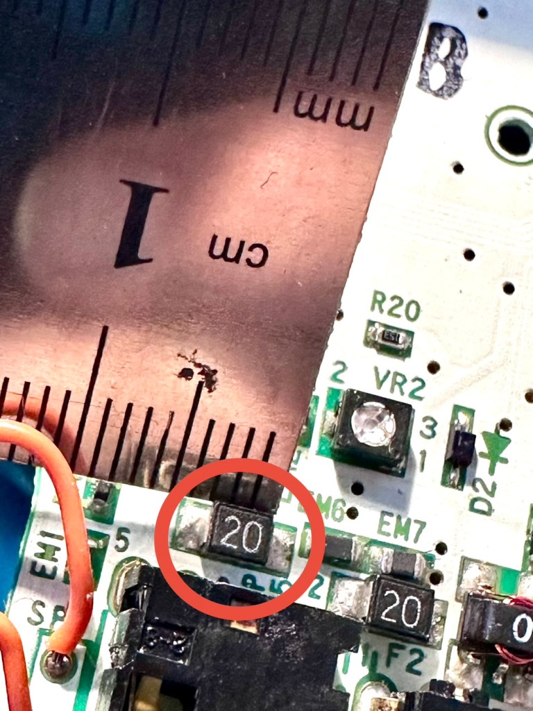
Just for information the fuse that needs replacing is approximately 4mm in width. You can see the scale in this picture taken alongside a ruler.
The tiny suspect fuse
Let’s get on with the repair.
Repair:
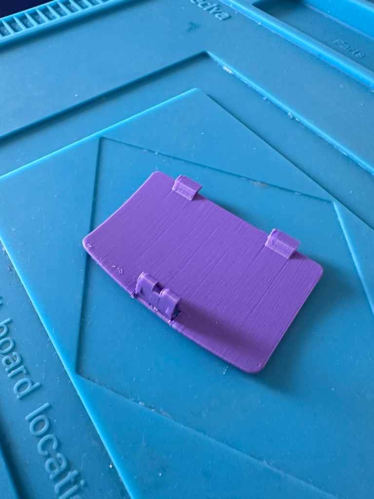
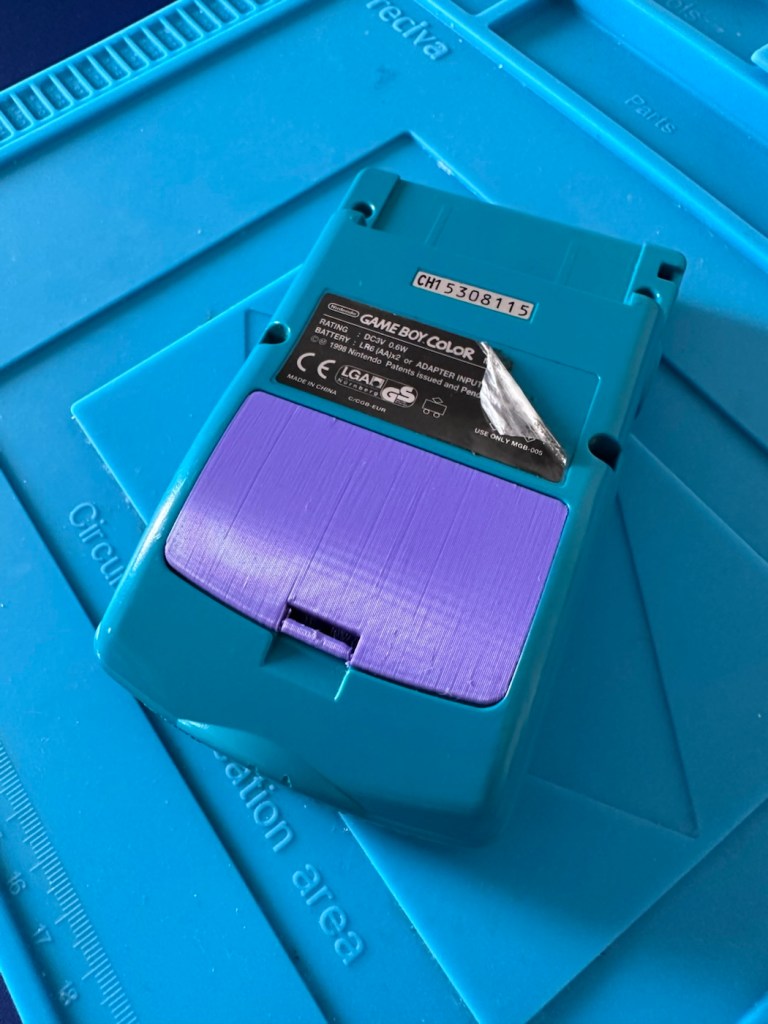
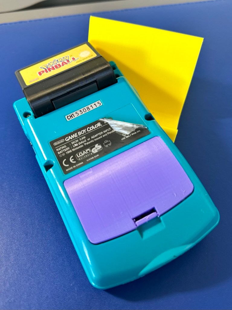
First off I’ve printed a replacement battery door cover. As stated earlier I don’t have any “Teal” filament so I’ve printed it out on a purple filament. For the purposes of practicality (holding the batteries in place) it will serve a purpose whilst carrying out the repairs.
The 3D printed cover in place
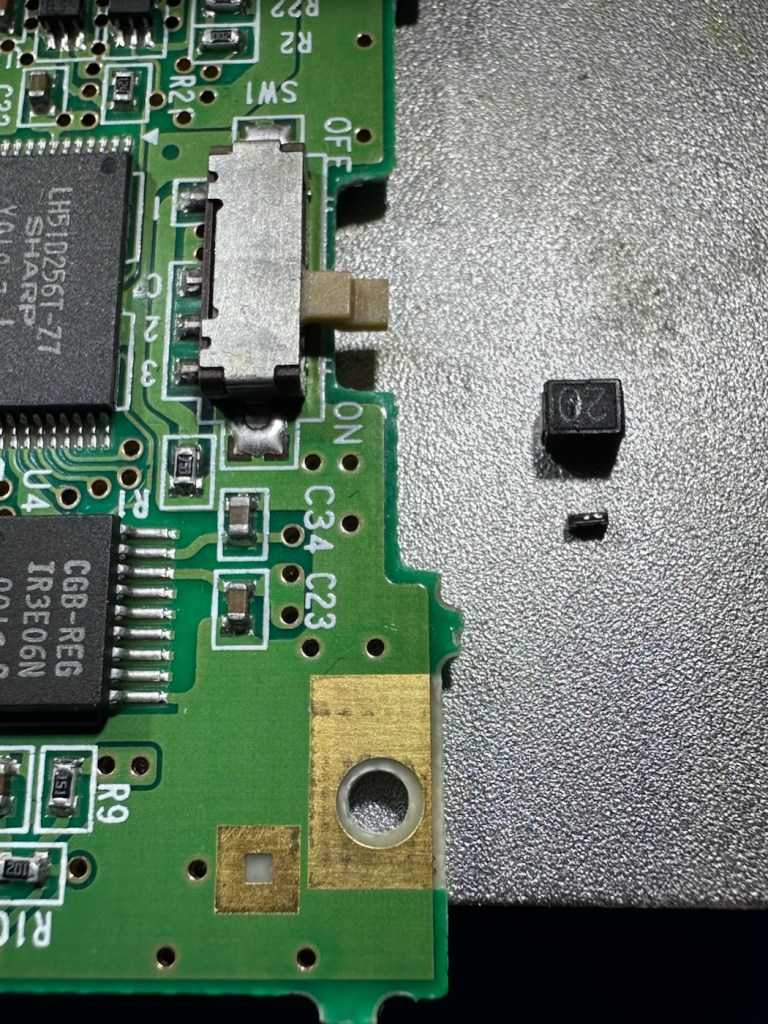
I have a replacement fuse, this work will now have to take place under the microscope as it’s just so tiny, think grain of rice size and you will understand just how small this component is, and it’s amazing that a component so tiny can completely shut down a unit such as this.
The supplied fuse is even smaller than the one on the board. If the original was 4mm then this one is probably around 1-2mm it really is minute. Here’s a comparison of them side by side on the microscope base.
Tiny and teeny tiny….
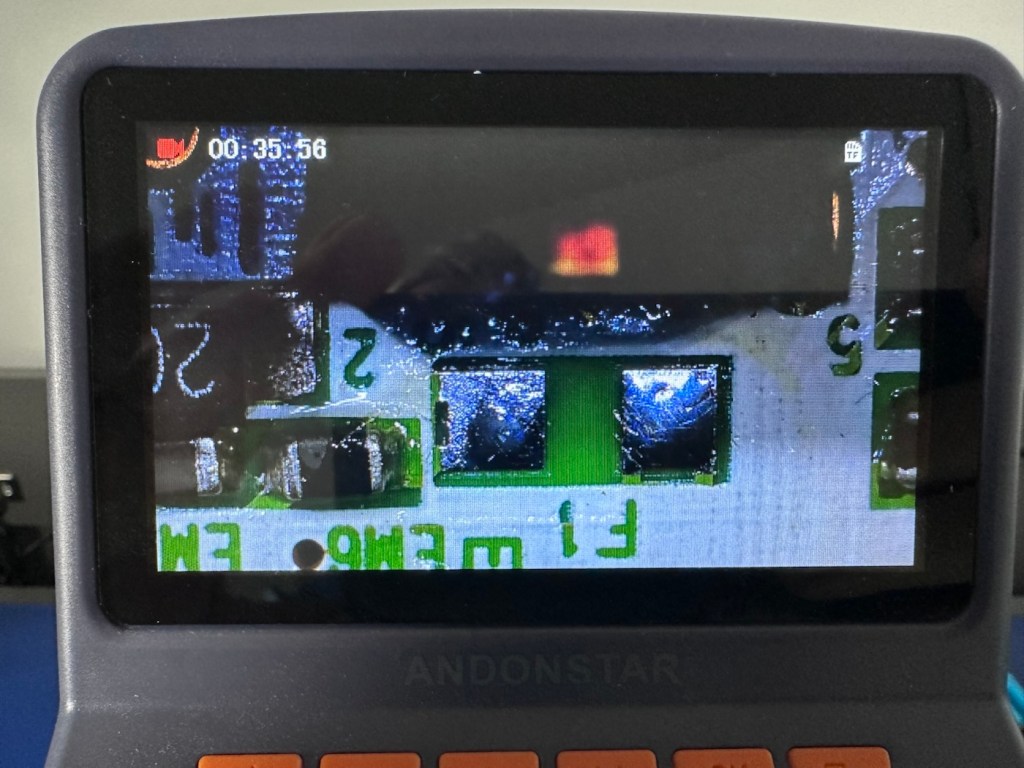
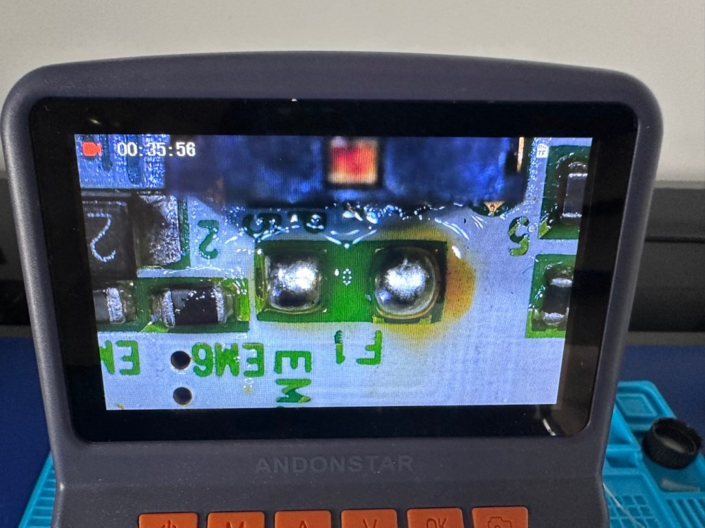
That said I’ve removed the old fuse, wicked away the old solder and applied some flux and a couple of new dabs of solder. Compared to these new fuses the solder looks massive, I can assure you it isn’t and is greatly magnified.
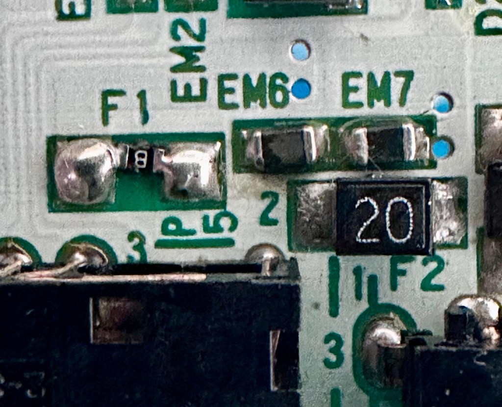
Pads cleanedTwo new blobs of solderNew fuse “B” compared to the size of its original counterpart “20”
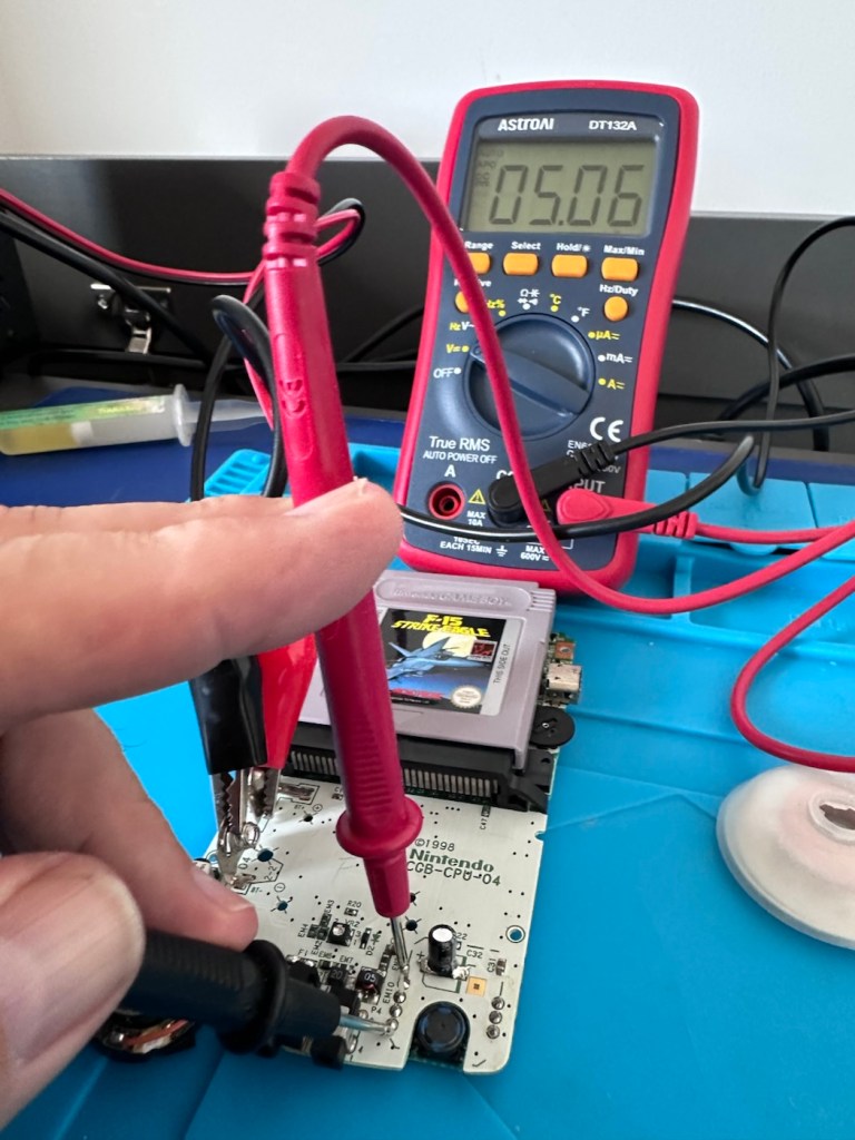
With the bench power supply providing 3v I’m able to use the multimeter to confirm that the fuses are both working, however there is another issue and I suspect it is something I discussed earlier, but omitted to heed my own advice, about good housekeeping. I’ll come to that in a second.
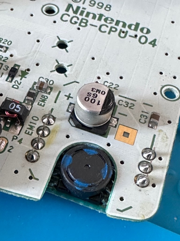
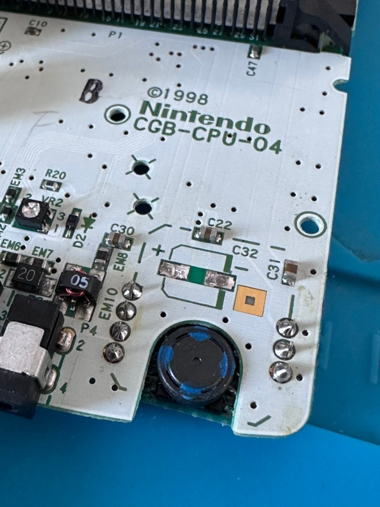
Power is getting around on the 3v rail and is not an issue. However at the Dc converter I’m not getting the 5v or 13.6v rail, so there is another issue. The new fuse has dropped out again, and this is good as it proves it works. I let it cool for 30 seconds and it is back up and working and I’m able to continue tracing the fault. The big capacitor C32 that sits beside the DC-DC converter appears to be carrying a short, it is probably this that has caused the fuse to previously fail.
And my good advice was to change these capacitors for good housekeeping purposes…..and I didn’t.
Guess what I will be doing next?
There are three Capacitors on the main board and below you can see what their primary functions are:
C32 (Main Power / DC-DC Filter): 100µF, 6.3V (Filters the incoming voltage; if faulty, the system won’t boot or will repeatedly reset).
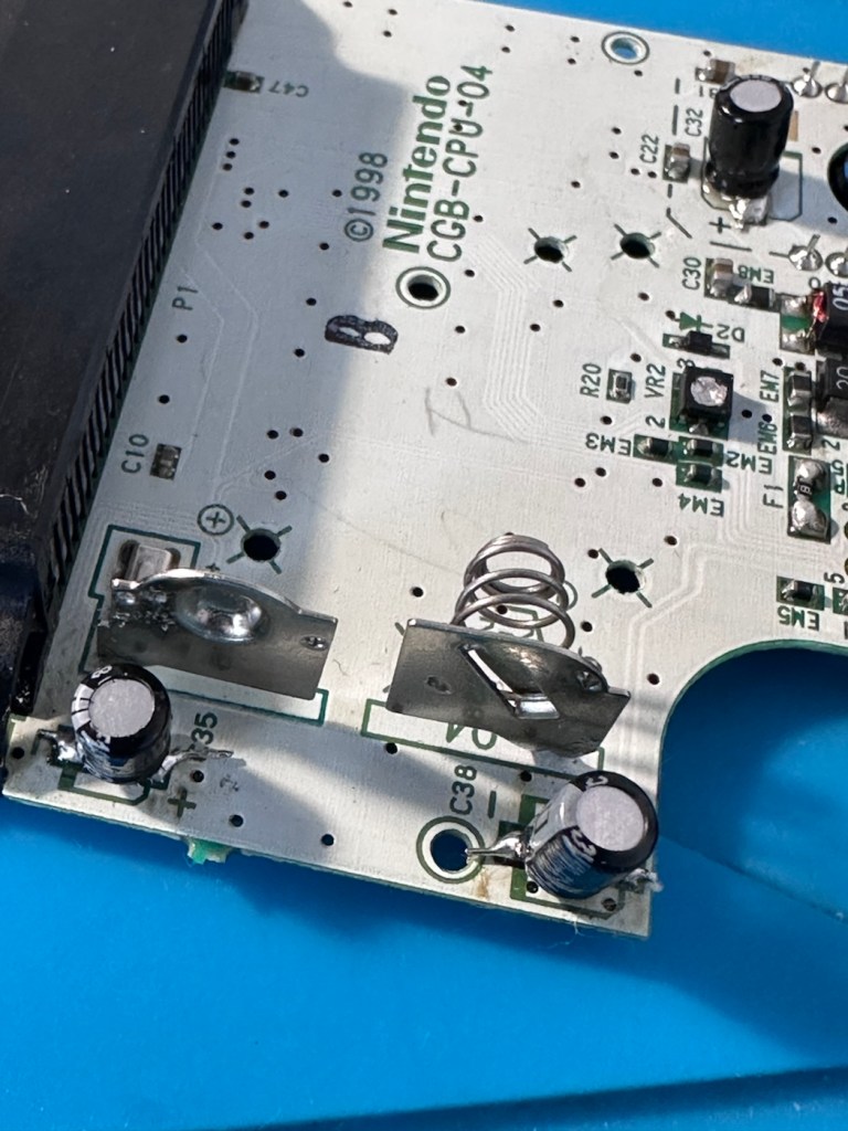
C35 (LCD Display Filter): 22µF, 16V (Stabilises the voltage to the liquid crystal screen; if faulty, it results in a dim or washed-out image).
C38 (Audio Amplifier / Sound): 100µF, 4V (Powers the speaker and headphone output; a failure here is the leading cause of whisper-quiet audio).
Ok. Fortunately I have plenty of capacitors in my spares box so I was able to replace the three capacitors with no issue.
Faulty power CapacitorCleaned and readyAll three Capacitors replaced
This done I then decided, prior to any reassembly to see if the power was now being distributed as it should, and I’m pleased to say it is. We have the full range of voltages now coming out of the DC-DC converter.
All expected voltages now present.
Now let’s get the unit reassembled, cleaned and then get some tasty pics taken👍
Result:
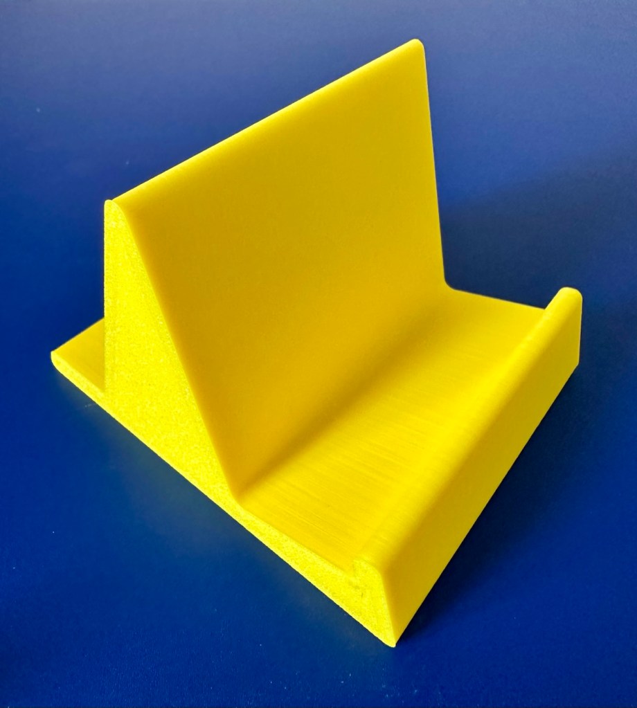
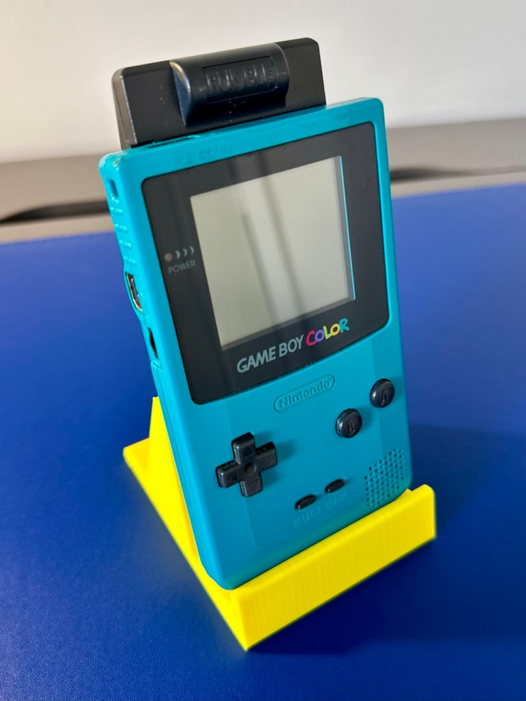
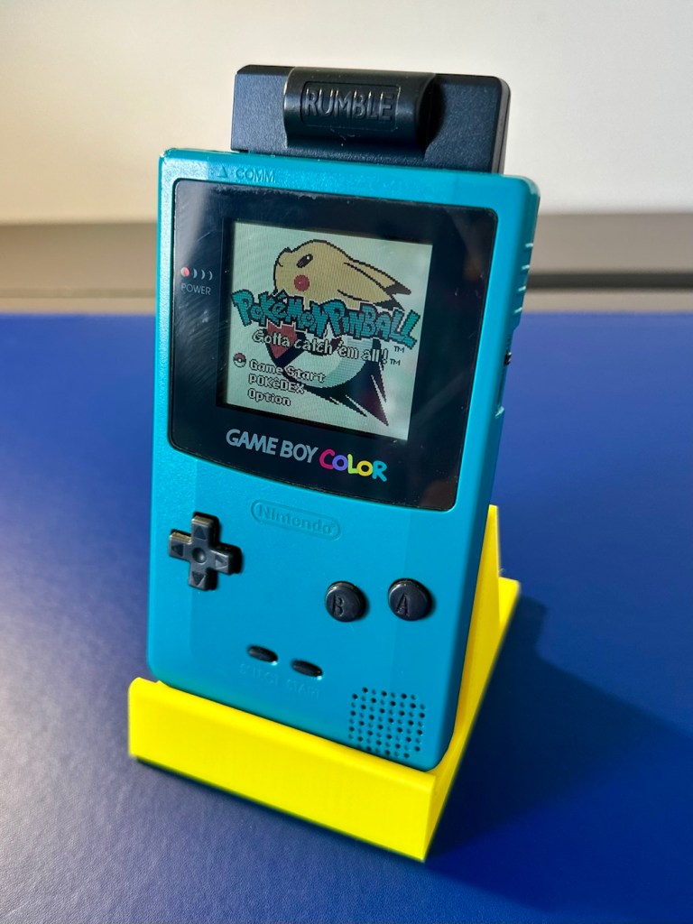
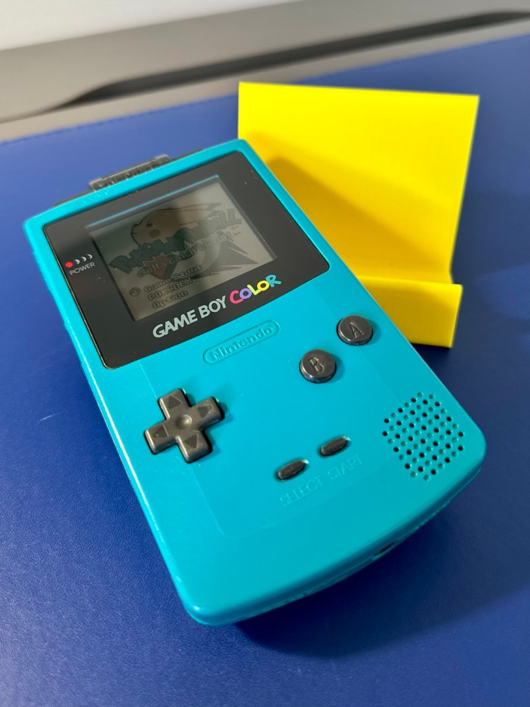
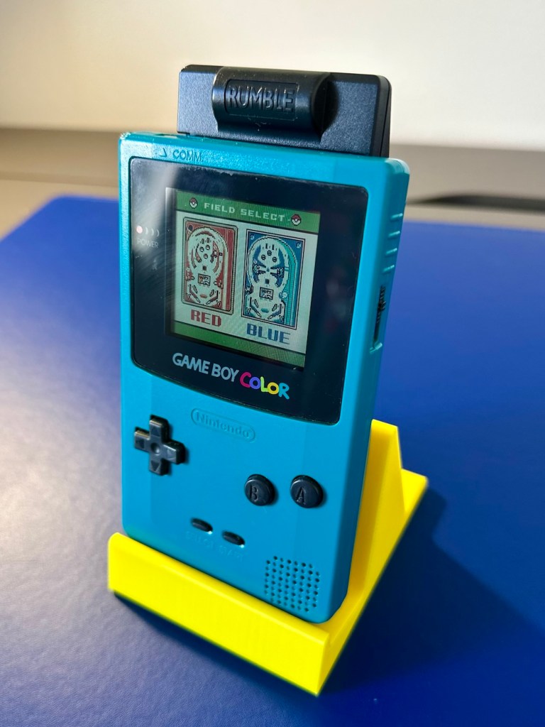
To finish it off and whilst the 3D printer was still warm, I’ve printed a simple brightly coloured yellow display stand to show it off on.
A new printed display stand
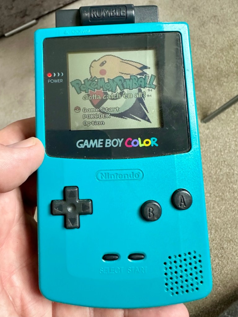
After a good clean the unit is now in a perfectly good working order. The fault appears to have been the faulty capacitors and battery contamination all probably combining to make the power fuse fail, a perfect storm if you like. The fuse and three capacitors have now been replaced to breathe new life into this game console. Cosmetically it’s still tatty and would probably benefit from a new outer shell and some labelling, however it works and to be honest that is all that really matters.
A small video showing the unit working Looks different but it works, it’s just a patchwork quilt of a project
I wonder how many of these items just get thrown away because they don’t work? This probably took me about three hours in total with diagnostics and repair. Another piece of retro history restored, now joining my original Gameboy classic as part of my collection.
It’s been a pleasing little project, enjoyable and educational and it’s always good to hear the familiar beeps when it springs back into action.
Another one saved from landfill.
Thanks for passing by, as always it’s very much appreciated.
A pocket computer from 2004 that needs a little attention. Let’s get it working.
What the listing stated:
Dell Axim X50V Handheld PDA with Windows Mobile 2003 SE. The PDA is in a used working condition and advertised as for spares or repair due to a faulty battery cover switch, It is also missing its rubber feet and SD slot cover.
The Battery has recently been replaced.
Comes complete with the following.
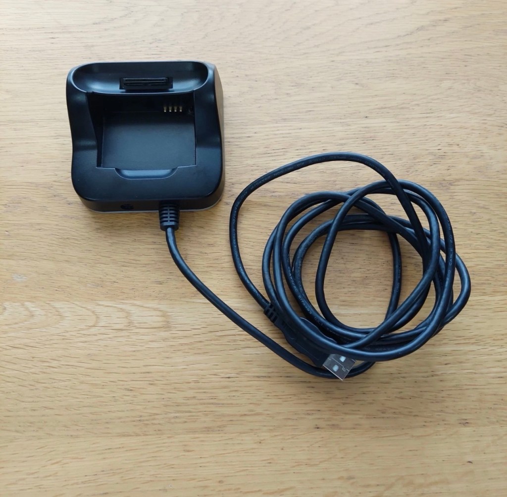
Desktop Cradle
Power Supply (Damaged lead, please see photo)
Windows Mobile 2003 Second Edition Companion CD
3D Game Pack for Dell AXIM X50V
Please see photos for overall condition.
EBay
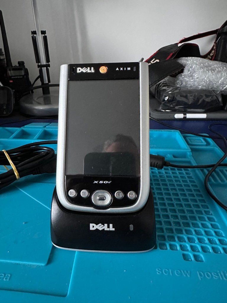
The purchased Dell Axim X50V
Here’s some info regarding these units:
The Dell Axim X50v was a high-end Personal Digital Assistant (PDA) released in late 2004. It was a flagship device in the Axim line, notable for its advanced multimedia capabilities, specifically its VGA screen and dedicated graphics accelerator.
Key Technical Specifications
Processor: 624 MHz Intel XScale PXA270.
Display: 3.7-inch transflective VGA TFT color display with \(480 \times 640\) resolution.
Graphics: Intel 2700G multimedia accelerator with 16MB of dedicated video memory.
Memory: 128MB Intel StrataFlash ROM and 64MB SDRAM.
Operating System: Originally shipped with Microsoft Windows Mobile 2003 Second Edition.
Expansion Slots: Dual slots featuring one CompactFlash (CF) Type II and one Secure Digital (SD/MMC) slot with SDIO support.
Connectivity: Integrated 802.11b Wi-Fi, Bluetooth 1.2, and Infrared (IrDA).
Features and Performance
Multimedia & Gaming: The Intel 2700G chip allowed for smooth 3D gaming and high-quality video playback, which were advanced for its time.
Design: Compared to previous Axim models, the X50 series featured a sleeker design with rounded edges and a curved base.
Battery: It uses a user-replaceable 1100 mAh Lithium-Ion battery.
Software Upgrades: While an official upgrade to Windows Mobile 5.0 was released, some users found it ran slower than the original OS due to the slow NOR flash memory used in the X50 series.
Multiple on line sources
Let’s await its arrival to see what we have.
Assessment:
The package has arrived, very well packaged. I have enough bubble wrap now to to last for quite some while.
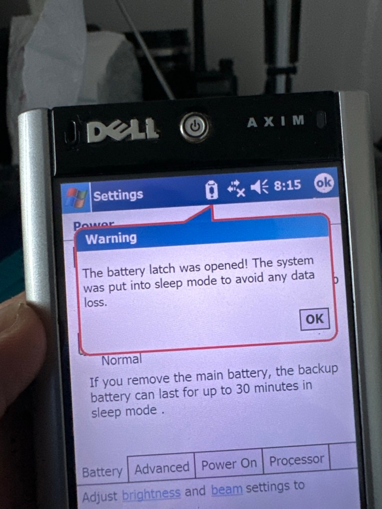
The item turns on, and appears to be doing what it should and then without even touching the back of the unit, an error appears on the screen.
A common fault apparently
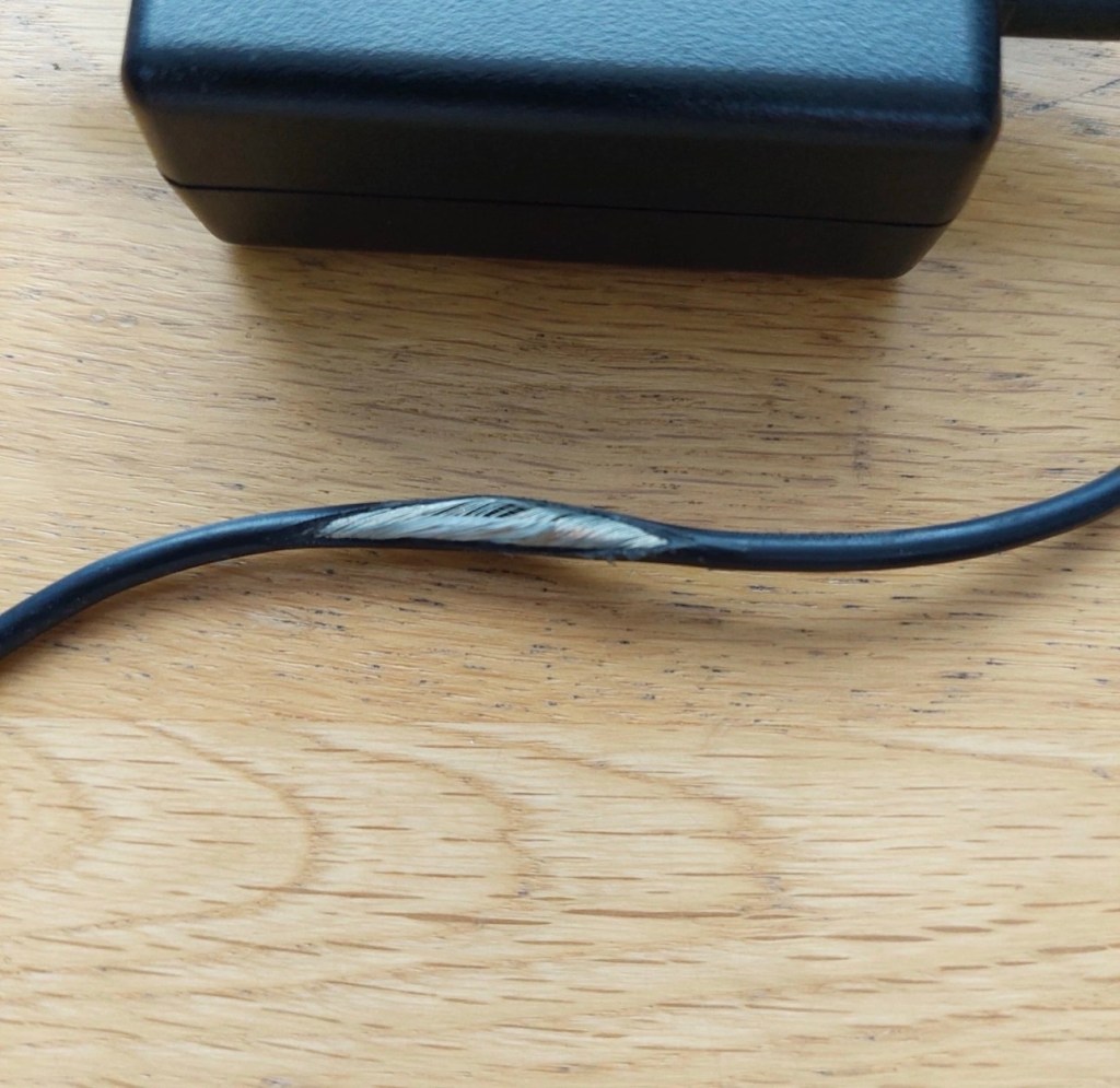
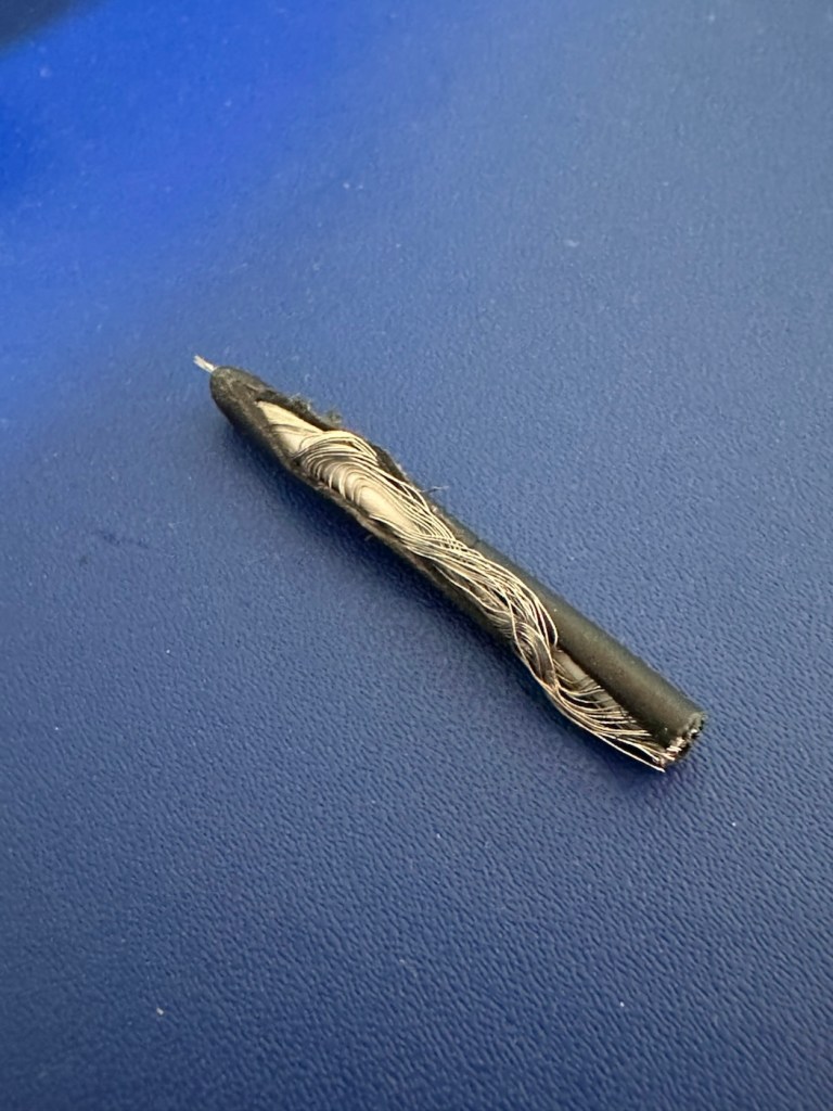
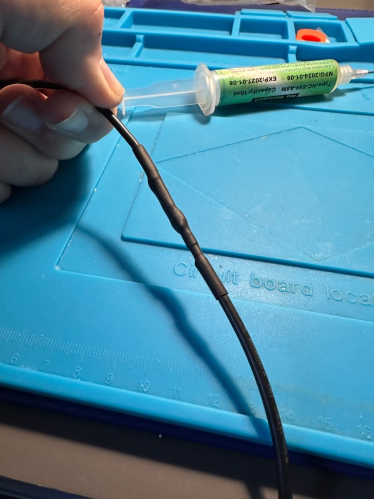
On the cable directly from the charger unit there appears to be some damaged cable sheath. I have tested the power output and flexing this area does not cause any interruptions to the power supply, it appears to be that only the external earthing of the cable is exposed, so I am happy that it will be fine to just apply some heat shrink tubing to this portion so that the cabling inside is no longer exposed. It looks as if at sometime someone has probably used a knife instead of the correct tooling to access the unit.
Exposed earthing
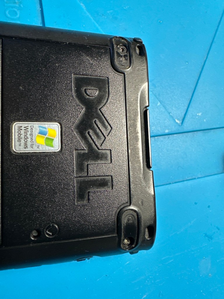
There are a couple of rubber feet missing, that just so happen to cover screws that allow access to the unit, further strengthening my suspicions that this unit has been previously accessed internally.
Missing rubber feet
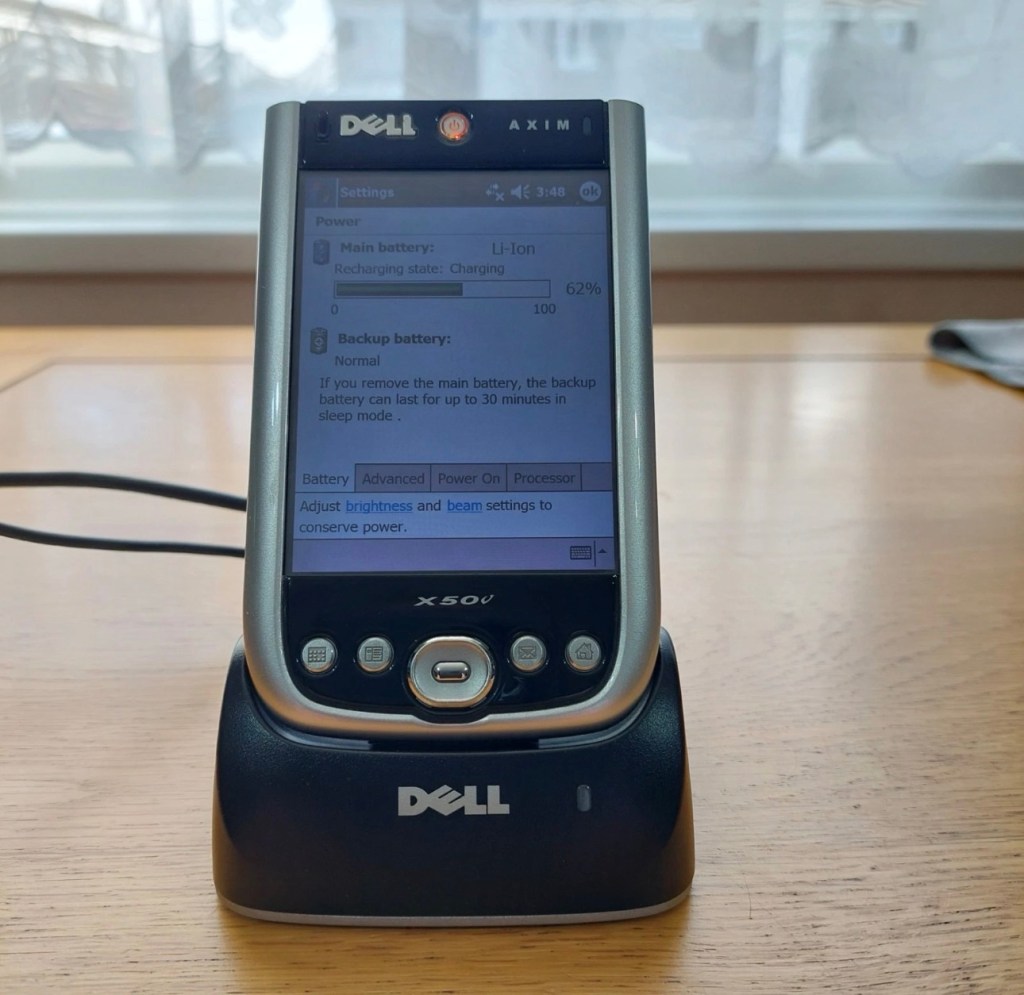
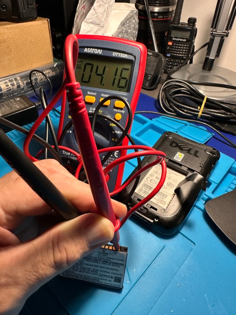
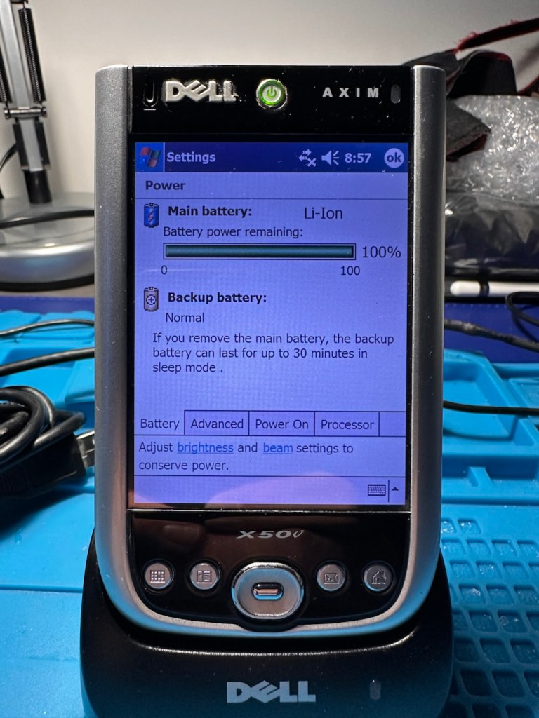
The battery is new, and is holding a good charge of 4.16v at an indicted 100% indication, and it is rated at 3.7v so this appears to be a healthy battery.
Battery holds a good charge
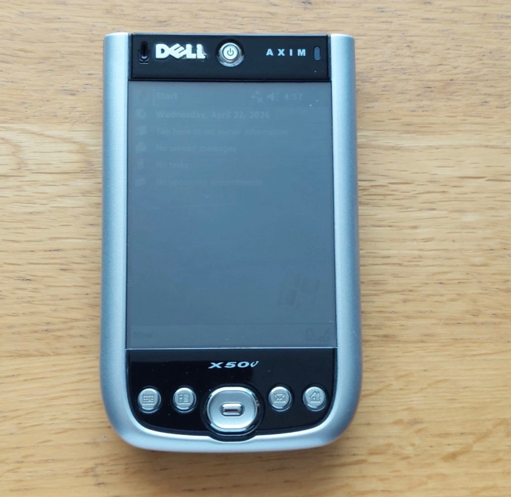
Cosmetically this is a nice unit for its age, it has a stylus pen included, along with a charging cradle and original software that came with the unit. There is a small SD card slot cover that is missing, however this is not an issue as I will probably install a small SD card to fill that void. It can also take CF cards and there is also a blanking plate installed to fill that portion of the top of the unit.
Let’s get repairing…
Repair:
I’ve gone straight in at the charger cable and have chopped the offending portion out. I’ve had to do this to be able to get some suitably sized shrink tubing in place. With the wires exposed I strip them back, tin them with some solder and, then finally connect them back together ensuring they are suitably insulated from each other, and safe and secure. It doesn’t look pretty, but it’s safer than it was.
Chopped out sectionAll insulated and heat shrunk
I’ve tested the output with a multimeter and the output is around 6 volts as stated on the power pack, so no issues there.
With the charging cable all sorted it’s time to look at the error message problem associated with the battery latch.
The Dell Axim X50v battery latch often degrades, triggering a false “battery door open” warning or sudden sleep mode shutdown. If your device is frequently going to sleep on its own or reporting a false “battery door open” error, it is typically caused by a loose, dirty, or misaligned latch switch inside the device.
There are a number of options we can go through to attempt to alleviate this issue:
Clean the Contacts: Power down the device, remove the battery, and gently clean the small plastic sensor switch and surrounding contacts inside the battery cavity with a cotton swab dipped in isopropyl alcohol.
Mechanical Shim: Over time, the plastic door can warp, failing to press the microswitch down. By placing a tiny, folded piece of paper inside the microswitch channel to force it into the “closed” position. Then snap the battery door into place.
Permanent Bypass: For an advanced fix, you can bypass the switch entirely by soldering the connections or using conductive paint to bridge the gap on the motherboard, ensuring the system always thinks the door is closed.
Replace the Door or Latch: If the physical latch or door is broken or entirely missing, replacement battery doors can still be sourced from specialty PDA parts sites.
Taking the above suggested remedial actions into consideration I’m going to approach this repair combining two of the above suggestions. Firstly I will clean the contacts as in the first option, this is standard work practice for me. I will probably use a contact cleaner rather than IPA in this instance. I will ignore suggestion number two, as that’s a temporary “Bodge job” fix that should only really be used to test for an issue. The third suggestion of the permanent bypass is what I will use should action number one not be successful, the error is one of those pain in the butt errors that are really unnecessary, and serve no real purpose at all, so let’s permanently disable its ability to reappear. The door itself is in a good order and does not require replacement therefore cancelling out suggestion number four.
So. To recap I will go with suggestions one and three.
Let’s get going then….
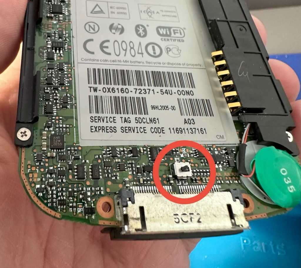
Four small star screws are all that need to be removed to get the shell open. Inside everything looks lovely and clean and there sitting at the bottom of the main board is the tiny switch that is causing the issues.
The switch that’s causing the issues
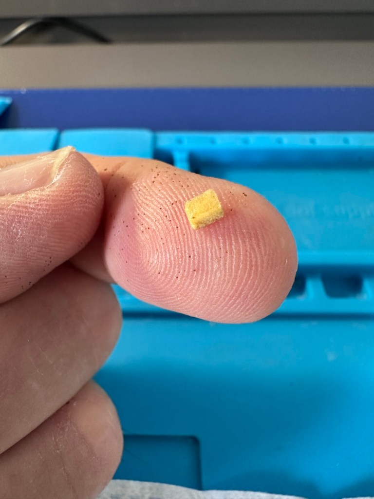
Immediately opposite this switch on the battery panel switch is a small piece of felt that I presume was originally set in place to hold the switch down.
The tiny piece of felt
Well, it had moved and was sitting in the wrong place. I’ve cut a small piece of felt that I use for repairing light seals on cameras, cut this to size and placed it in the correct position. The small switch is like a rocker switch, I have cleaned this with IPA and it is now clean. A quick clean around the main board and now it is time to reassemble.
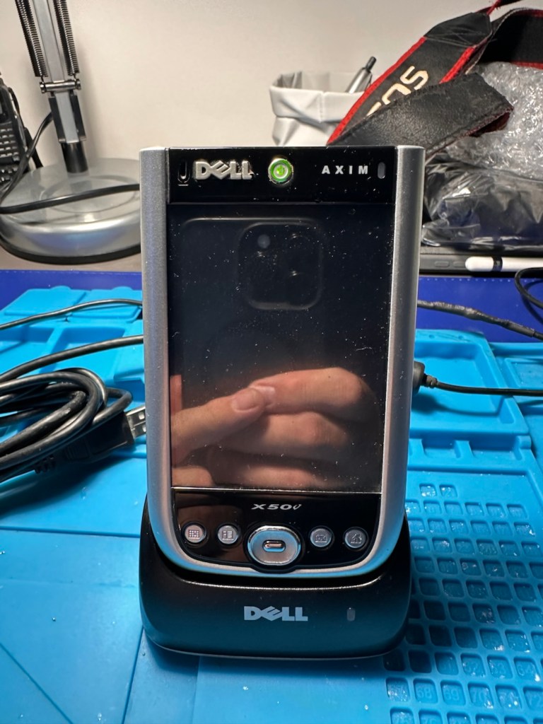
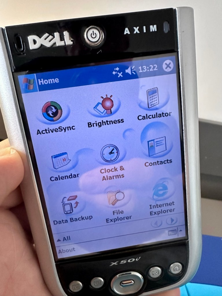
Now all back together, battery now in place and the unit switches on fine. A little shake of the battery panel cover, and no error message appears. In fact no error message appears until I physically open the battery panel, but once it is put back in place and locked it again, the fault clears. The repair as such has been successful. You can see in the picture below, the battery error at the top of the screen, that results in a restricted use, until it is cleared. A standard fault with these units, now repaired.
Fault No fault
Everything is working fine on this unit, it voice records, the stylus is present and I have all the original software. It’s year 2K compliant and is working as good now as it ever has, the only items I have not replaced are the two small rubber pads used as feet. Not really necessary and if I ever find anything suitable, I’ll utilise it.
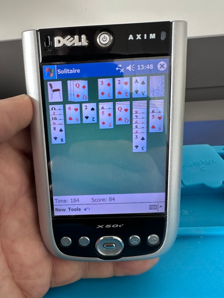
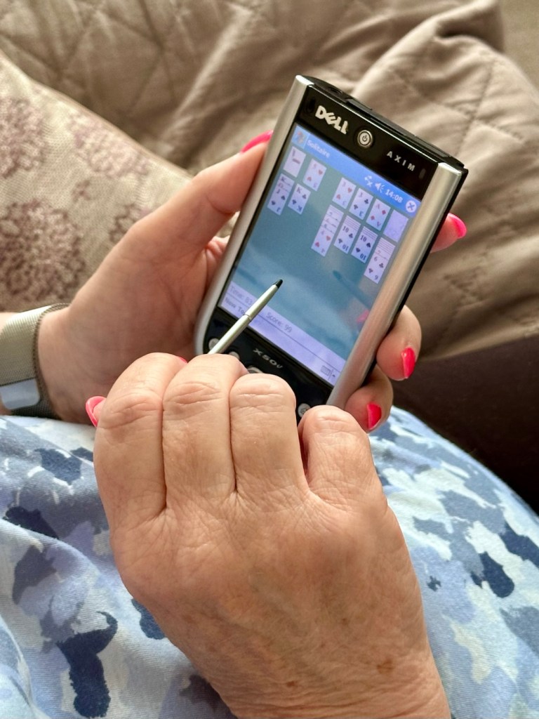
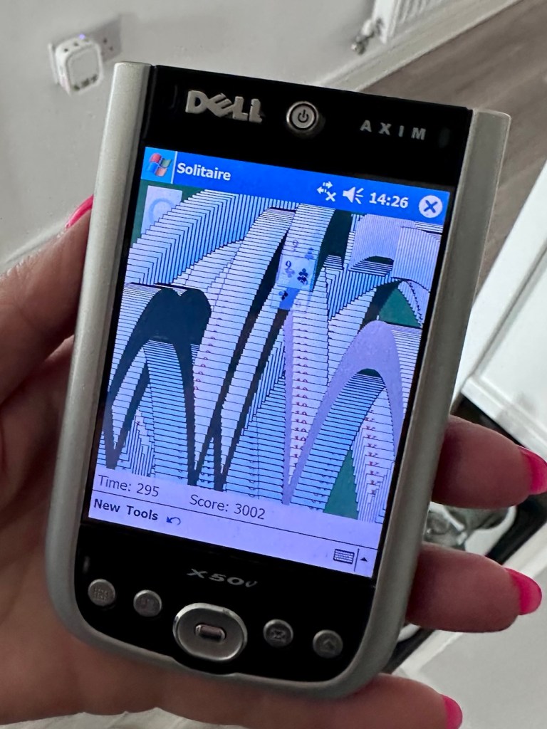
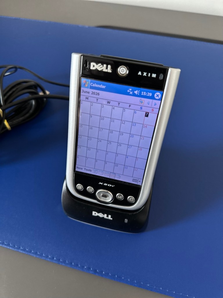
I’ve given this unit probably the best soak test it could ever be given, a rather long session playing original solitaire with my wife. She’s played for a little over an hour solid now and no error codes or faults have appeared.
The ultimate soak test
I’m happy we have a good working item, resurrected from impending doom in a landfill. Let’s get it cleaned and finished off.
Result:
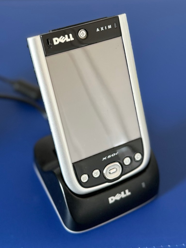
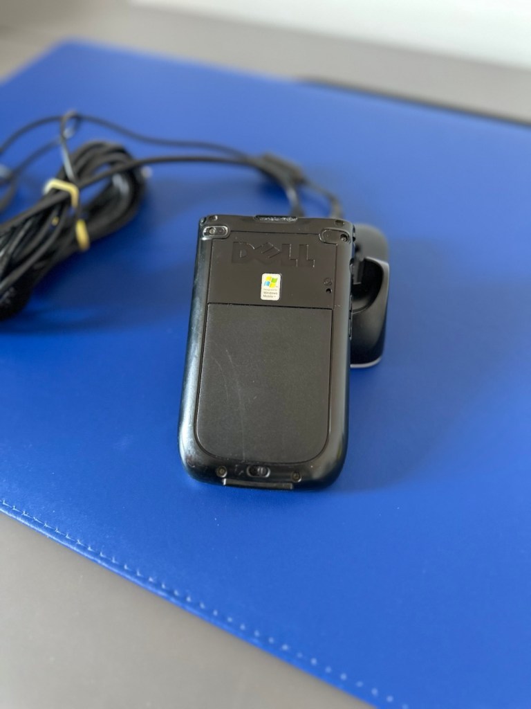
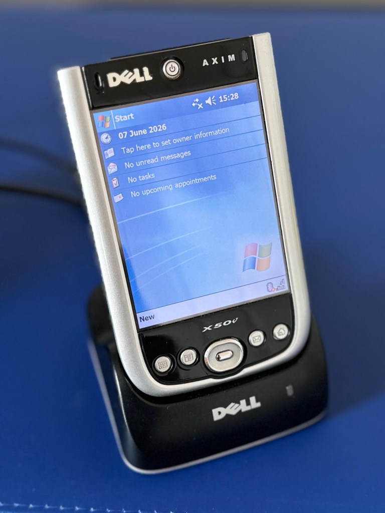
The unit has cleaned up nicely, and for an item that is 22 years old, pre smartphone technology, it has aged really well.
Looking smart
I just love these items from probably the best tech area there ever was, 90s through to year 2k and just beyond. Technology was developing, it was new and exciting with lots of choice unlike today.
It gives me a chance to now go back and buy the items I’d never be able to afford as a youngster/teenager, even though they may be broken. And that’s the fun of it all, learning, repairing and enjoying a momentary rerun of good times gone by.
I love it. And another item is repaired, saved from landfill and another piece of tech history goes on for others to enjoy for a few more years to come.
Thanks for passing by. It’s always very much appreciated.







You must be logged in to post a comment.