Amstrad Notepad NC100

What the listing said:

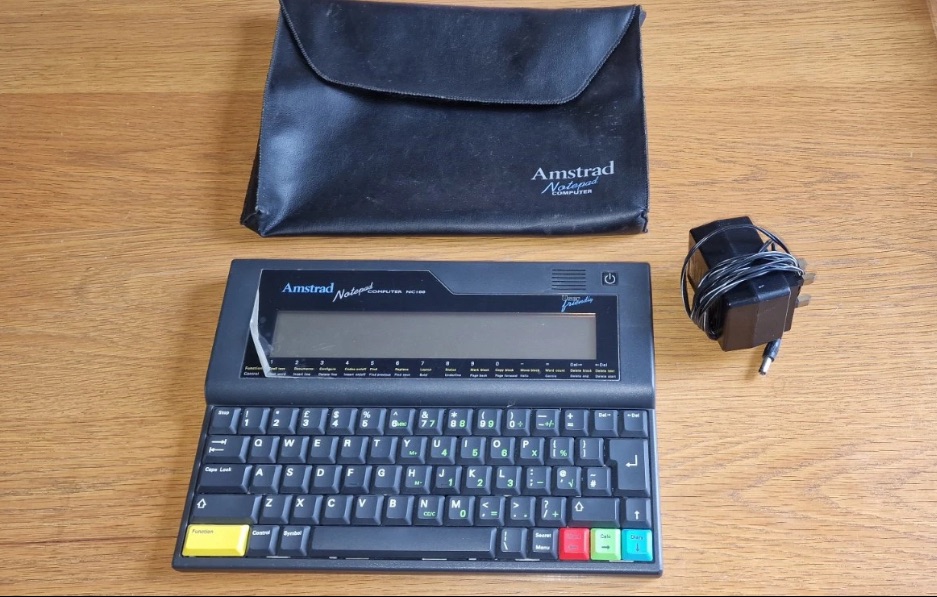
Amstrad Notepad NC100+ Vinyl Case 

Not working not powering on, the vinyl case has some marks and scratches.

EBay

I’ve been after one of these for a little while, I’ve just been awaiting one at a good price and this one became available, post included at £30GBP, they retailed for £199Gbp back in 1992. It says it is not working but that’s good in my eyes as it makes these posts more appealing, as it gives me something to repair. I don’t know what the issue is off hand as the post didn’t state that, but I do know these items have suffered with capacitor problems over time, but that is not necessarily the case here. We will just have to wait until we do the assessment on its arrival. And as it comes from around the early 90s it fits right in with my modus operandi. And this little cutie dates from 1992.

Here’s a little history behind this unit courtesy of Wikipedia:

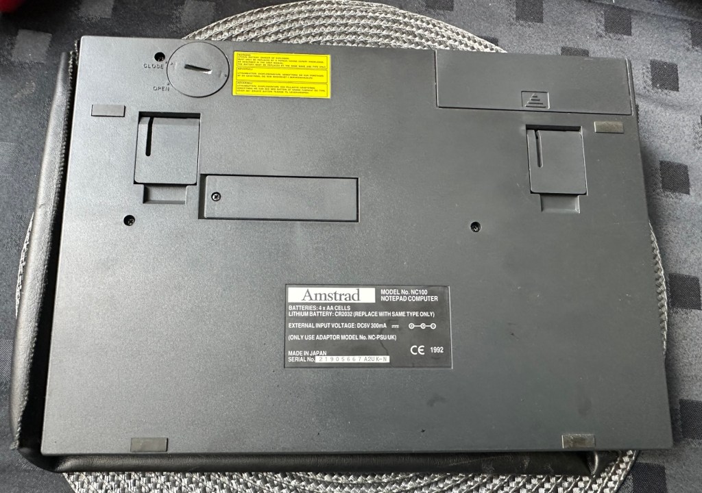
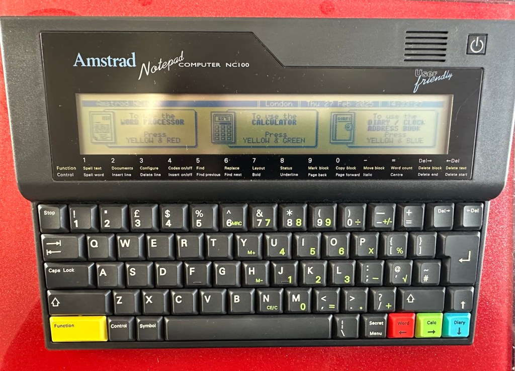
The Amstrad NC100 Notepad is an A4-size, portable Z80-based notebook computer, released by Amstrad in July 1992. It featured 64 KB of RAM, 256KB of Rom, the Protextword processor, various organiser-like facilities (diary, address book and time manager), a simple calculator, and a version of the BBC BASIC interpreter. The computer’s design, evocative of the TRS-80 Model 100, features a screen with 80 character columns by eight rows, and not backlit, but this let the NC100 run for up to 20 hours on four standard AA cellbatteries. There was an RS-232serial port, a parallel port for connecting a printer, and a PC card socket, by means of which the computer’s memory could be expanded up to 1 MB.

Assessment

The unit has arrived and cosmetically it is in very good condition apart from the peeling plastic screen cover. A little bit of dust and grime, all keys in good order and no dinks or dents. the vinyl bag is a little tatty but that’s not a problem, it’s obviously done it’s job over the years due to the good condition of the unit.

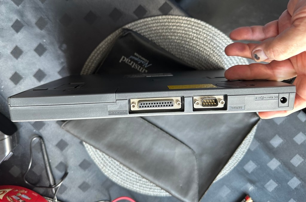
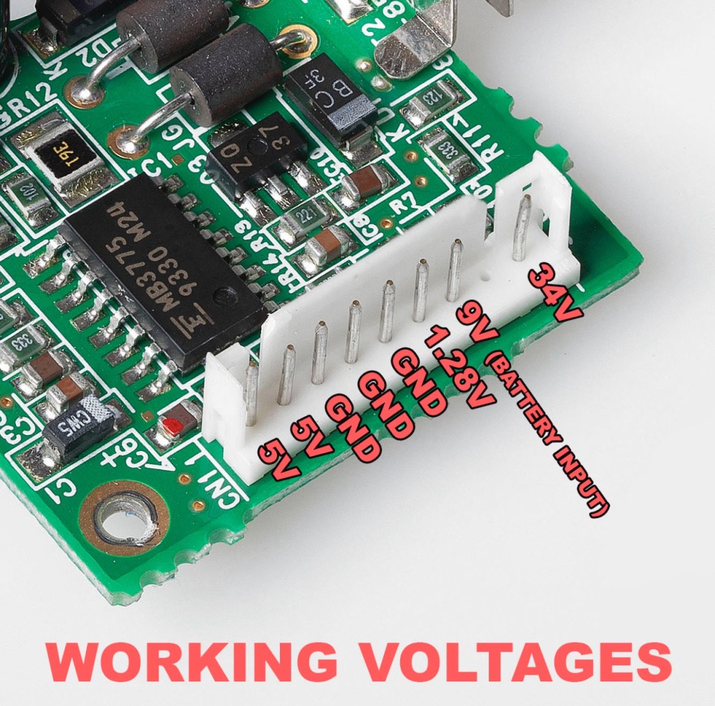
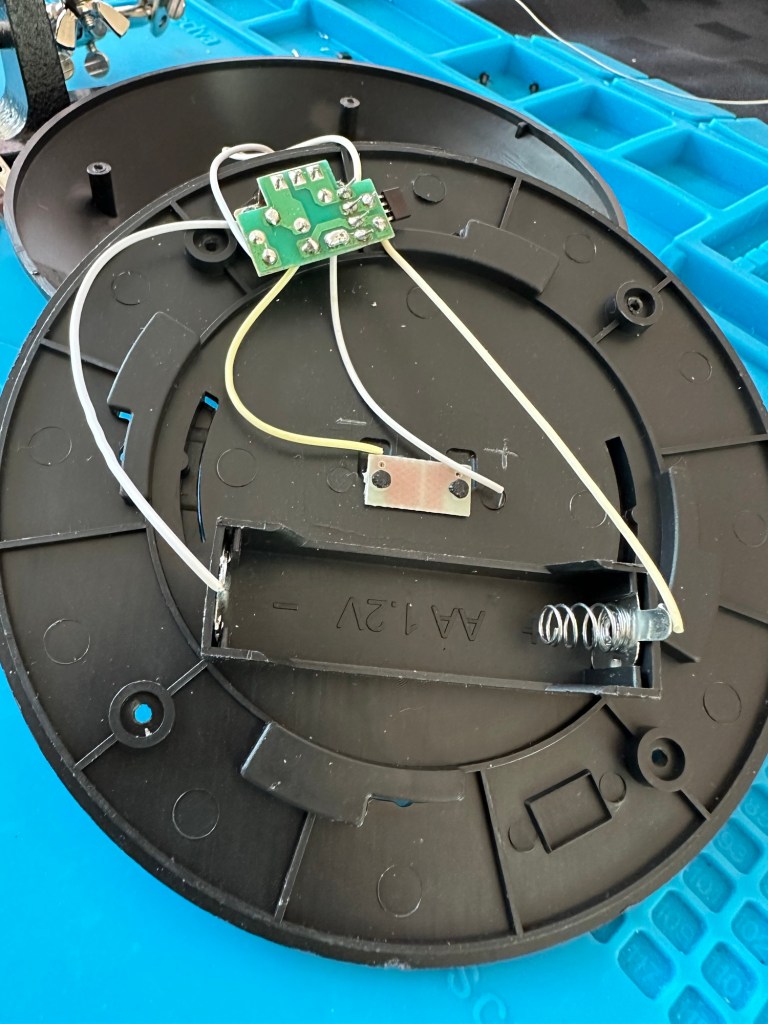
So down to testing. First thing I’ve done is check the power supply is giving a 6.5 v output and this is ok.

Power supply doing what it should.

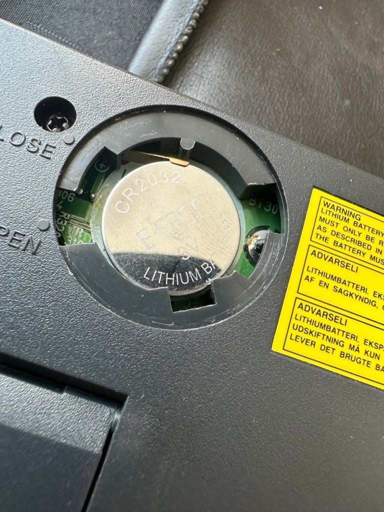
Secondly I’ve put 4 AA batteries in place and turned the unit on but then it abruptly stops, displaying a lithium battery issue.

Lithium battery warning

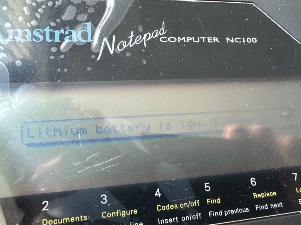
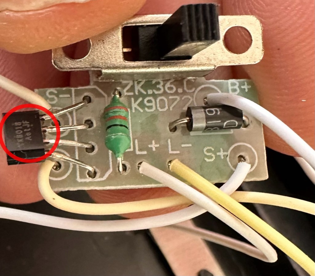
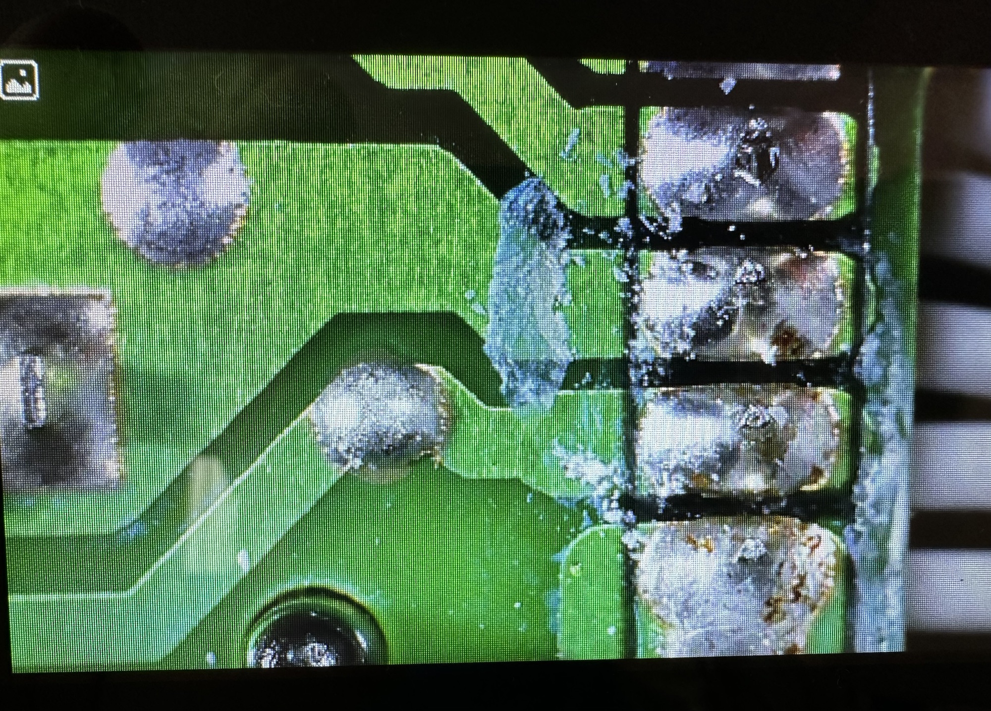
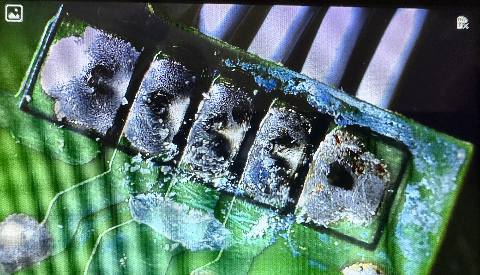
The lithium battery is an old CMOS type battery, a CR2032 coin battery. This is the battery that keeps the info in the system when you turn it off. I thought I’d run this through the multimeter and was surprised with the voltage I saw, the battery seemed fine to me at 2.8v, so I replaced it with a new one measuring 3.4v. And the issue came up again…..head scratching time!

Looking on line it seems there is an issue with the lithium cell battery contacts on these units when they are being resurrected to modern day usage, time has not been good to them. The coin contacts have now been cleaned and slightly bent to ensure a better contact and hey presto it’s operational with no further issues.

Battery contacts needed cleaning and repositioning

The main AA battery contacts are fine and the external supply is doing what it should. Now let’s look at sorting that screen issue.

Quite simply there were two options, use a bit of heat to try and stick the plastic down, but I decided against this as it would not lay flat, it had too many kinks in it. So the only other option was to remove it and this is what I did, it peeled off with no issues. In time I will see if I can get a suitable replacement but to be honest it isn’t really required as I’m not going to be using it that often.

Let’s get that screen cover off

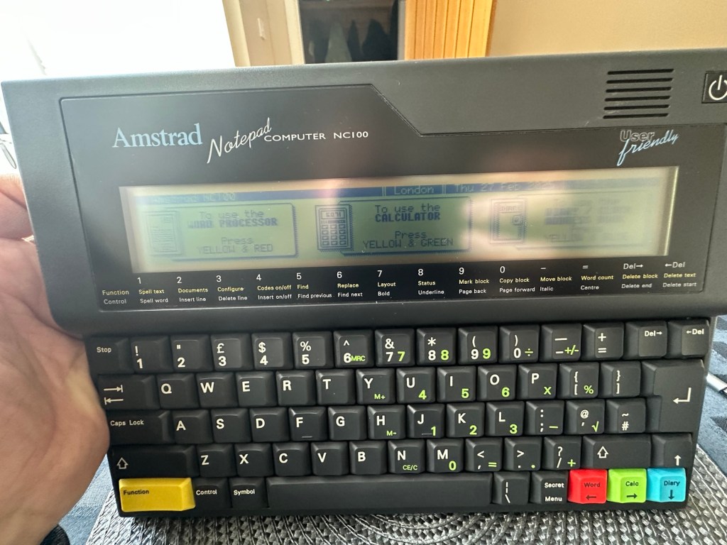
I’ve tried every function and keystroke of the board and all is good there are no issues and I now have a perfectly acceptable unit for my collection. It looks like i have had a second win against the “Untested” brigade who sell on EBay. This was the simplest of repairs and the issues are readily available to research on line. There is no excuse for not looking into the issues, when a good unit like this can now sell for up to three times the amount that I paid for it.

Your loss my win. Another one kept from landfill.

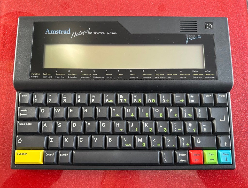
I’ve given the unit a good polish and I think you’ll agree that the project has come up good.

Now to just go and read the user manual on line to see if I’ve missed anything. Thanks for passing by, as always it’s most appreciated.

Modified Sega game gear 2110-50

You may wish to refer to this post: Sega game gear 2110-50 where I purchased a non working Sega Game gear and brought it back to life.

The (I thought it was repaired) Game gear

I’m now ready to do some modifications on this unit, and I will save the replaced items for use on later projects.

Pretty much every Game Gear that was ever produced (and that is approximately 10.6 million units) has suffered with the dreaded (Capacitor plague) that I have discussed in an older post. The first job that is recommended to be carried out when purchasing an old Game Gear is to replace the old capacitors, it’s quite an easy task and nine times out of ten will remedy any issues that you have and allow you to continue gaming for years to come.

However there are other issues.

The screen is an old tube powered system that is exceptionally power hungry, you can replace this with much superior LCD versions, I’m withholding from doing this at the moment as I want to get as much use out of the old screen, and to be honest my unit doesn’t require replacement just yet, there’s still life in the old girl. I’m sure that this will be a future project though.

Occasionally after doing the capacitor replacement on the power board, other components such as a small IC and three transistors that control voltages across the system, start to misbehave causing the unit to switch off after just a few seconds. This is currently occurring with mine and I am intending to replace these components to see if this sorts out my issue. I have also ordered a replacement power board from China that is a fraction of the cost of a European one, it may work, it may not but if the change out of components dosen’t work at least I’ll have an alternative option.

There are a few checks we can do prior to replacement of these components on the power board that will confirm the various voltages required by the system. It’s best that these tests are done prior to diving in head first to replace them. You could be just wasting time. You may need a new power board or maybe even consider converting to a rechargeable battery system. It’s all doable.

Expected voltages – photo courtesy Retrosix

Here are the results from my test of voltages on the power board, I’ve injected 9v via a bench power supply to the battery contacts on the board:

  • At the 34v pin I had 0v
  • At the 9v pin I had 8.9v
  • At the 1.28v pin I had 1.28v
  • The three ground pins read as ground
  • At the two 5v pins I had 0v

So as a result I obviously have an issue with the 5v rail and the 34v rail, I believe the 5v rail is the one that affects the boot sequence and the 34v is not an issue at the start up, however, it’s there for a reason and this simple test proves there is an issue. I will therefore only change the IC and three transistors as the capacitors were changed when I did a full recap.

For my modifications I am getting a new clean amp duo audio board with dual speakers instead of the single mono one that is standard. This is an upgrade on the original, extremely efficient and with better sound processing.

I am also replacing the shell with a new Blue case and glass to replace the scuffed old screen, this shell also has dual speaker outlets to compliment the audio board replacement. The shell is already prepped to accept a rechargeable battery system should I decide to install it at a later date.

I shall be getting these upgrades from Retrosix who specialise in supplies and modifications for gaming consoles.

All the items have now arrived and the first thing I’m going to do is sort out the replacement IC and transistors on the power board. The rest is fairly straightforward. However they have sent me the wrong shell, a single speaker one instead of a dual speaker one, so I’ve now got to await a replacement, annoying!

Scratch that, they are saying that they never did have any duo speaker ones even though they were advertising them on their site ( as per picture above..) and after a protracted discussion with the supplier / owner i’ve come to the conclusion that he might think he is a wizard at modding and designing circuitry but is totally and utterly inept at customer service, he wouldn’t know good service if it bit him in the ass. Hey ho on we go, it is what it is.

If you choose to use them in the future then just be aware. They have an uncanny knack of trying to pin their inadequacies and mistakes on you, the customer. Caveat Emptor – as they say.

So now the sound will be original mono, but hopefully improved. I have a spare speaker and mount as a result and I can use the new clean amp duo board in a mono configuration. Should I get a duo speaker shell sometime in the future I can always do a swap out.

Today I’ve taken the empty new shell and installed the new audio card and speaker, as well as the new buttons and silicon pads. I’ve then installed the main board minus the power board that still needs the new components.

I’ve also installed the new front lens on the unit and I must say it looks nice.

New front lens on unit

Let’s get to the difficult bit, replacing the components on the power board. I’m not joking when saying that some of these items are not much bigger than a grain of rice. I suspect a lot of bad language will be used here, as this is a new level of soldering for me. I’ve never replaced anything so small before. If I balls it up I’ll just have to await my cheap Chinese power board.

Ok, the power board from Ali Express got here really quick, to be honest even before I could set some time aside to change the components on the old board, so therefore I’ve decided to try this new board as a straight swap.

I will keep the the components and the old board to use at a later date.

First though I have used the bench power supply to test it is ok, and it’s a big tick on all voltages as per the test I did on the old board. All voltages are stable and consistent, so I have secured the board in place and put the required batteries inside. Works perfectly.

Back together, awaiting the big switch on
Working perfectly

I now have a perfectly good looking updated Game gear that I am exceptionally pleased with. The sound system is a good upgrade, it has a really loud volume (adjustable) and is crisp. The powerboard from China at a total cost of £10.80 is an absolute bargain, and works perfectly with good stable voltages. The case is good, fits well and the lens is clean easy to install and scratch free, the whole thing looks brand new.

Two old rebuilds, rejuvenated

I now have two perfectly good looking and working examples of 90’s retro rivalry in perfect working condition. The plan is to display these in the house, on a custom made display. I’ve really enjoyed working on this little project and I’m made up with the outcome.

The only things left to be done would be to change the power supplies to rechargeable and to change the screens to new IPS/LCD screens, but I don’t think I’m going to do that on these two, I’m keeping them original or as close as possible to original, I want to keep these as they are, to cherish in this condition for as long as I can.

I love them. And they are fantastic.

A bit of this and a bit of tat

If you were going to open up a shop, what would you sell?

I miss the stores such as Maplins (aka Radio Shack). When I used to go into town with the wife at the weekends she would go do her thing and I would go into and spend a lot of time in Maplins. For her it was like a kind of Man Crèche as she knew where she could easily find me ( don’t forget this was in the days when mobile communication was in its infancy)

Here you could buy individual electrical components, it must have been murder doing a stocktake. But I loved it. All the kits, all the ideas, and all the boys toys you could dream of.

I really miss Maplins.

I’d also love to have a store where you could get hold of good quality retro games, and equipment at a reasonable price, not at rip off prices that are currently being seen on auction sites. People really do have inflated ideas of the worth of items only a few decades old, they really are becoming the new antiquities.

So maybe the shop I’d like to own would be a mix of Maplins and a quality second hand store of memories. Somewhere the hobbyist or dreamer could walk into and spend a good while reminiscing, and maybe buying some stuff.

That would be nice.

Sega game gear 2110-50

What the listing stated:

SEGA GAME GEAR Console FAULTY

Ebay

And that was it. Faulty. What’s faulty? I’ll not know until it arrives as i didn’t ask. Foolish perhaps, but I was looking for a challenge and something I could later mod. I think I’ve found it.

I must admit I was looking for a cheap way into a retro gaming repair and I believe this was it. Most damaged game gear units seem to be averaging around the £42GBP price but I managed to get this 2110-50 version at a lower price of £28GBP (and I may have got a game with it, let’s see what arrives!). However I don’t know what the heck is wrong with it but I suspect it’s the usual issue that has plagued these 90s retro units since their inception where the capacitors fail catastrophically.

There is probably not a single one of these units out there that has not suffered this issue or is certainly guaranteed to do so sometime in the not too distant future. Imagine how many of these units have just been discarded as junk considering that 10.62 Million units were sold up to and including its discontinuation date in April 1997….scary!

The first recommendation from anyone in the know is to change the caps before they start popping and corroding everything. I have a set of replacement caps ready in anticipation.

My hope is that this unit has not yet reached that corrosion stage….fingers crossed 🤞

Hurry along now Mr.Postman….

Both Game gear and replacement Caps have arrived. And I’m really happy as there is a game in the unit as well “Columns” Sega’s answer to Nintendos Tetris. A nice bonus.

The unit turns on, there is no sound, and only a very feint green glow when the unit is held at an angle. It’s looking very much like it is the old Capacitor problem.

The unit is in surprisingly good order with scuffs and minor scratches as you expect from a game that’s around 30yrs old. The lens scuffs aren’t an issue as a new lens is relatively cheap. But that isn’t the problem as it stands. Let’s get it working and I can worry about that later in the repair process.

There are no signs of any corrosion in the battery compartments and this pleases me. I only hope that when the unit is opened there are no obvious signs of corrosion on the boards.

Wish me luck, I’m going in….

Overall I’m happy with the condition inside, no bad corrosion, however it’s noticeable that a few capacitors have leaked. The worst seems to be C39 on the main board, it’s easy to see the residue.

Main board Capacitor C39 leaking

This unit separates into three boards. An audio board, a power board and the main board. This is a twin asic board, I have removed the audio and power boards as these are the first and possibly the easiest for me to be working on.

The audio board has 5 capacitors that require replacing, I can see some leakage on the rear of board but not in the area of the capacitors. I suspect that this is factory flux though I could be wrong. When I remove the caps I’ll clean all the pads and use IPA to clean so this should sort that issue out.

Audio board Leakage or Flux

The power board only has three Capacitors that require changing, however it’s clear to see here that C5 has been leaking.

Powerboard C5 leakage

Let’s get on with the removal and replacement of these 8 components. The other 11 are on the main board.

Well that didn’t go too bad. A few minor position changes due to the capacitor types being a different size on the board compared to the 1990s version.

It was obvious that there had been leakage on these two boards due to the fishy smell that arose when the soldering iron was used. That said, the old capacitors came off without too much problem. I used solder braid to remove the old solder and then gave a good clean of the board with IPA prior to re tinning the pads prior to putting the caps back in place.

I knew there wasn’t a big issue with the power board as this was sort of working prior to this project. This was the easiest board to solder as it had through the board components, pretty much a straight swap but for better components.

The audio board was different as I had to reposition these pots so the case could close properly and the shielding could go back into place with no issues. Again I used the same process of unsoldering, cleaning thoroughly and then tinning the pads.

These two boards are now complete. As a test I thought I’d reassemble the unit and see if there was any improvement. Power came on and the red led lit, this was a good sign that there was power and I’d not messed anything up. Secondly there was sound, we didn’t have that before so this is a definite improvement on what we originally had. Volume works with just a couple of occasional crackles so I may have to use some more contact cleaner here.

We have sound

So far, so good. No real improvement to the picture even though you can see something is trying to come through. That said I’m hoping the replacement of the caps on the main board will help this. So with no further a do, let’s get the main board finished.

Just got home from work, now time to get these last 11 caps done. All the old ones removed, all the pads wicked to remove the old solder and what a stink of old fish, these capacitors had definitely died.

All cleaned with some IPA to rid of all the debris and then fluxed and tinned the pads ready for the new capacitors to go into place, I’ve got this off to a tee now and these went on a lot quicker, easier and tidier than the last lot. I’m a lot more competent now, and feel more confident with this process.

Had a little trouble getting it all back together, a couple of the new caps had to be tweaked slightly as they were in the way of a screw post, the earth shield was also causing issues and shorting the system, again a bit of captain tape helped shield an exposed component. All this done I put the strap back on and loaded up the batteries. Switched on and red light, all looking good…

All working

Very happy with the fix, that was my first Cap replacement and I’m happy with my first attempt. Again you learn from these attempts and the reluctance I initially experienced was just nerves. I’d be more than happy to do more of these fixes, maybe using the modern surface mount components next time.

Another one saved from landfill, I wonder how many of the 10.6 million more that were made of these have suffered that very fate. Scary.

Anyway, I’m looking at using this unit to do some mods, so this is going to be my test bed for other projects.

Simple fix, great outcome, I’m happy.

Big Trak CE3962 restoration

Big Trak CE3962

I refer you to the post I wrote earlier in June 24: Teenage jealousies revisited

Here I purchased the toy I most wanted back in my teenage years. Unfortunately I wasn’t available to get the original MB version produced in 1979 so I had to settle for the latter “improved” version made by Zeon Ltd that was made in 2010.

It’s arrived and to be honest dosen’t look too shabby, needs a bit of a clean up and maybe some new transfers applying but we’ll get to that at another time, for now we need to try and get the machine up and running.

I’ve eventually managed to get the lid off. This unit was built to ensure that it was difficult to get into so repairs couldn’t be carried out. Some of the screws are buried under fascia dressings, and if you aren’t careful you could end up snapping some of the body shell.

With the two halves of the body shell detached it’s obvious there are some detached wires. One was a battery wire, one was a speaker wire. Oh if this was the issue wouldn’t it be great? But it wasn’t. I soldered these wires back into place, put the three D types in place and it was still dead.

I’ve now desoldered all connections from the circuit board to assist in carrying out checks for continuity and tracing voltage. I can also check the board under the microscope. I may change all the capacitors for SMD ones.

I started checking continuity and tracing voltages and was doing really well until I got to a large section of the main board where everything seemed dead and unresponsive. What the heck was going on here? And then I noticed the wire had detached from the positive probe of my multimeter thus ending any further testing for today. I need to order some new probes. Well, I’ve ordered some nice new probes and croc clip connectors as well, so as soon as they arrive I’ll get back on with the testing. They arrived and were damaged on arrival, so back to the drawing board.

I took the drive train to pieces and here it became apparent that a number of the cogs are damaged. I believe there is also some issues with the motion detector but I can’t confirm that until I get some power into the motors. I can’t find spare cogs online so I have ordered myself a second damaged unit to use as salvage. To be honest this new unit has all the transfers in place so I will probably use that shell and the guts of my original unit to form one complete Big Trak.

New donor Big Trak – better than my original one

The donor unit has arrived and boy I’m impressed. It’s in far better condition than my original one, so as expected this one will become the working unit and my original one will be come the donor. Any parts left over will be sold on as spares or even used on another damaged one if I can source it.

My new Bigtrak

If you look at the video above you will see the new Big Trak going through the motions. However the one thing it dosen’t do is turn. Could be a wheel sensor issue who knows. Good thing is that the cogs haven’t broken as the drive wheels are both solid and not free wheeling.

There are only two real issues with the donor here. Firstly it will not do the turn command and secondly, one of the drive wheels is damaged. Luckily I have a spare wheel so this was swapped over, some decals were missing but I coaxed these off my old truck with a hot air gun and reapplied them with no issues.

Looking into the drive issue meant opening the gear box. In here we have two magnetic independent gear controls that should have a gap between them, these two were stuck together thus rendering independent motor operations of the turning control useless.

I removed the two motors and repositioned them and the cogs holding the magnetic gear, this gave a gap of about 3mm that now allows the wheels to turn in opposite directions allowing the unit to turn.

Now the Magnetic sensors are adjusted….it turns

Whilst in this gear box I was able to confirm the issue with my old gear box and it really is all down to two damaged drive cogs that I need to obtain. I’m pleased with that as I could now get two good working units for just a small outlay once I can source some cogs. I will have to repair the wheel I removed to replace the one on my new unit however I have an idea how I’m going to remedy this and again it’s a low cost option. But that’s a job for another day.

2:18 of rebuild magic

So if you look at the video above, it’s the full fix that I posted on YouTube. Really pleased with this fix, again I’ve learned quite a bit about these units and I’m going to have immense fun programming it. My wife dosen’t understand my excitement over this toy, but all my old buddies and colleagues understand it as they grew up in the same era. Maybe it’s the male menopause, reliving the past and all that.

But hey, it keeps me occupied and out of mischief so who should worry about that

This one is going on my shelf so when the kids visit I can show them the joys of basic programming we experienced back in the day.

Job done.

Size isn’t everything… Apparently

Just a quick post, after having taken some time to think just how much electrical component’s have reduced in size in my lifetime.

What made you think this way? I hear you ask (or at least imagine that you ask.)

Well, today I had ten Audio amplifiers and fifty charging points delivered. Now, years ago I’d have probably had a large van deliver this little lot but today a small sized Jiffy bag came through my door containing all the above.

Ok the charging ports were micro usb ports and the audio amps were some small audio amps in an IC format needed for a current project I’m working on.

Amazing isn’t it just how far this technology has progressed. And shrunk in size.

My problem is that I’m easily impressed.

Impressive stuff.

Have a good day.

Garden solar lights

I purchased a pack of 5 of these cheap old garden lights from a local garden centre. I know if you buy cheap you pay twice but these did look quite reasonable. I know that most people only expect a season out of these lights however I try to look after mine, bringing them in during winter months when the garden isn’t being used and sunlight is non cooperative.

These were so full of promise, worked lovely for a few days and then two of them just didn’t work at all.

Broken garden solar lights

I took them apart and decided to test the batteries, both were showing 0.6v so i suspected the charge circuit was not working. When I put in a fully charged AA battery the lights came on but when exposed to light they remained on, so in a way I am right but it might be slightly more complicated. The battery isn’t charging, also the switch off is not occurring when exposed to light.

I’ve done a few tests using the multimeter, the solar panel is ok and giving a reasonable voltage under sunlight of 2.4v.

Solar panels working

The circuit board only consists of three components and two out of the three test ok. The issue seems to be with the YX8018 controller, the small four legged component in the pictures below.

Failed component circled
Failed YX8018 component

What is a YX8018 controller?

YX8018 is a high-performance solar lawn
lamp boost control chip, which is suitable for a solar lawn lamp powered by a 1.2V rechargeable
battery in series.

The main functions include charging control, boost drive, optical control, etc.
The solar lawn lamp mainly uses the energy of
the solar cell to work. When the sunlight shines on the solar cell during the day, the light energy is transformed into electric energy and stored in the battery, and then the battery provides power for the LED (light emitting diode) of the lawn lamp at night.

It has the advantages of safety, energy saving,
convenience and environmental protection.It is
applicable to solar products powered by one 1.2V
rechargeable battery.

Conrad electronic SE

YX8018 circuit diagram

This appears to be the culprit after some basic tests have been carried out, there is about a 16% failure rate in these components so I don’t hold out a great deal of hope for the two that I’ve ordered. I shall eventually order a stack of them from China but for now I wanted some a bit quicker so I have ordered locally.

Two arrived….i now need three

Well, the two components I ordered have arrived today. But now I need three, as in the week another one has suffered the same issue. On top of that I have dropped one of the units and the solar panel has parted company. I’m now sourcing some liquid solder that may assist with getting this problem sorted. As is normal with me this little project has escalated due to my utter clumsiness. I must do better in the future. (Sounds just like one of my old school reports.)

In place ready to solder

I dismantled the two units I previously mentioned and followed pretty much the same process with each. Desolder, remove component, wick solder, put new component in place and then put a semi charged battery back in.

All soldered

I left the lights in the sun for a couple of hours and the charge has lifted from 0.8 to just over 1.1 volts so I’m happy that the charge circuit is now working.

The final test was to turn on and see what happens. Good news, nothing seen until I covered the solar panel and then the lights came on. Excellent, job done and more items saved from landfill. I must say I was really happy with my soldering on this job, it appears to be getting better.

Now working

I just need another component for that other one I broke in the week. However I won’t bother you with that one 😂

Roberts Blutune T2 breakdown and fault finding

The radio has been received see here: Not just Dead….Fully dead and if I can’t get it going, I have at least brought a very tidy storage box.

What surprised me when first opening up this radio was the immense amount of boards and circuitry inside, I must admit I took a gulp at this and questioned my reasoning for purchasing the item. However it’s all a learning curve and I have to start somewhere, gone are the days of simple circuits on traditional radios (with big components).

I arrived home from work and sat myself down in the conservatory surrounded by test devices for about 4 hrs until I totally overloaded my self with information, creating more questions than answers, i decided to give up for the day and further research the potential faults for this unit via other sources.

To me the power board seems fine, power is going where it should, there appears to be no short circuits or component damage however in places there does seem to be some signs of leakage so I may have some components that need replacing or maybe it’s just remnants of flux and stuff left behind after initial construction.

None of this can be seen by the naked eye but it becomes apparent after being placed under my new toy an Andonstar microscope viewer. It’s at the entry end of the range but it is already becoming a game changer for me, due to my failing eyesight.

Andonstar AD106S

Copyright Andonstar

Further investigation appears to highlight an inherent issue with this range of radios when they just seem to stop working (probably why Roberts ceased production).

Generally the power board isn’t an issue, it all focuses around the display board where a controller to the screen has failed or the amplifier chip has failed, hooray I say! And then I find out both components are about the size of a grain of rice… Boo I say.

I have no experience at all in components this minuscule in size, but if I can’t get to the root cause and eliminate all other possibilities I will give it a go. In the meantime fault finding will go on between other jobs and this will continue to be a job in progress that will be revisited and updated as time goes by.

The plan short term is that I’m going to borrow a thermal camera and check if there are any hotspots under electrical load. You never know I might just find something.

I shall comeback to this project at a later date.

Thanks for passing by. Stay safe, be superb. You’re a star 🌟