

I recently posted an article regarding a low power decentralised radio network that you can read about here: Meshtastic
That post was an introduction to the mode, this post is my first attempt to assemble and program the equipment, and to try to create a presence on the Meshtastic network.
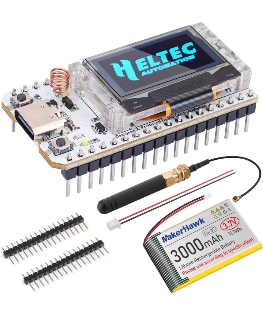
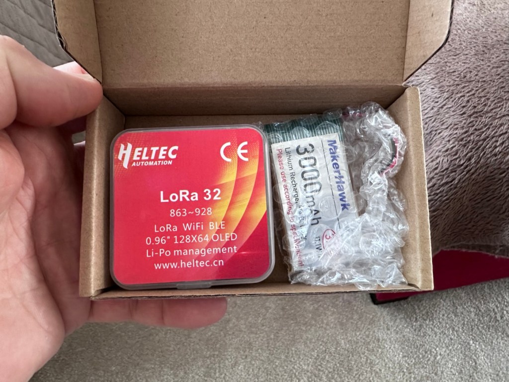
I’ve dived in and purchased a basic starter kit, the Heltec V3, and a separate GPS module, it’s my intention to install the GPS module once i get this up and working. The whole kit you see in the picture below is available in the UK and cost me a total of £34:19GBP. Other kits are available for a lower cost if you are prepared to await the delivery from China, however with my impatience on overdrive at the moment I just had to go ahead and buy it. That said i don’t think it’s too bad a price to pay for its combined parts.
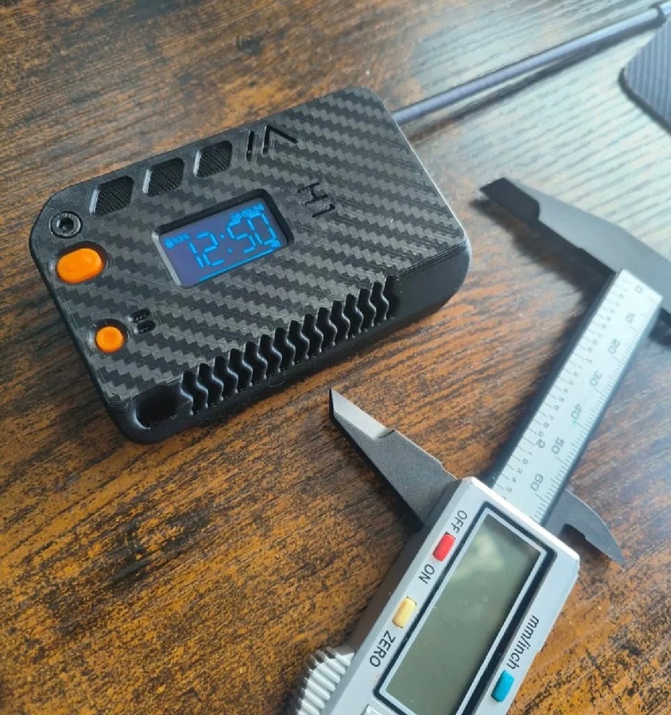
Preempting the kits arrival, I’ve downloaded a case from Makerworld by a designer called: @gux2K3 that I’ve uploaded to my 3D printer, it’s a basic case, but this purchased kit should fit it perfectly. It might not be sufficient for when I get the GPS module, but I’ll cross that bridge when I get to it.
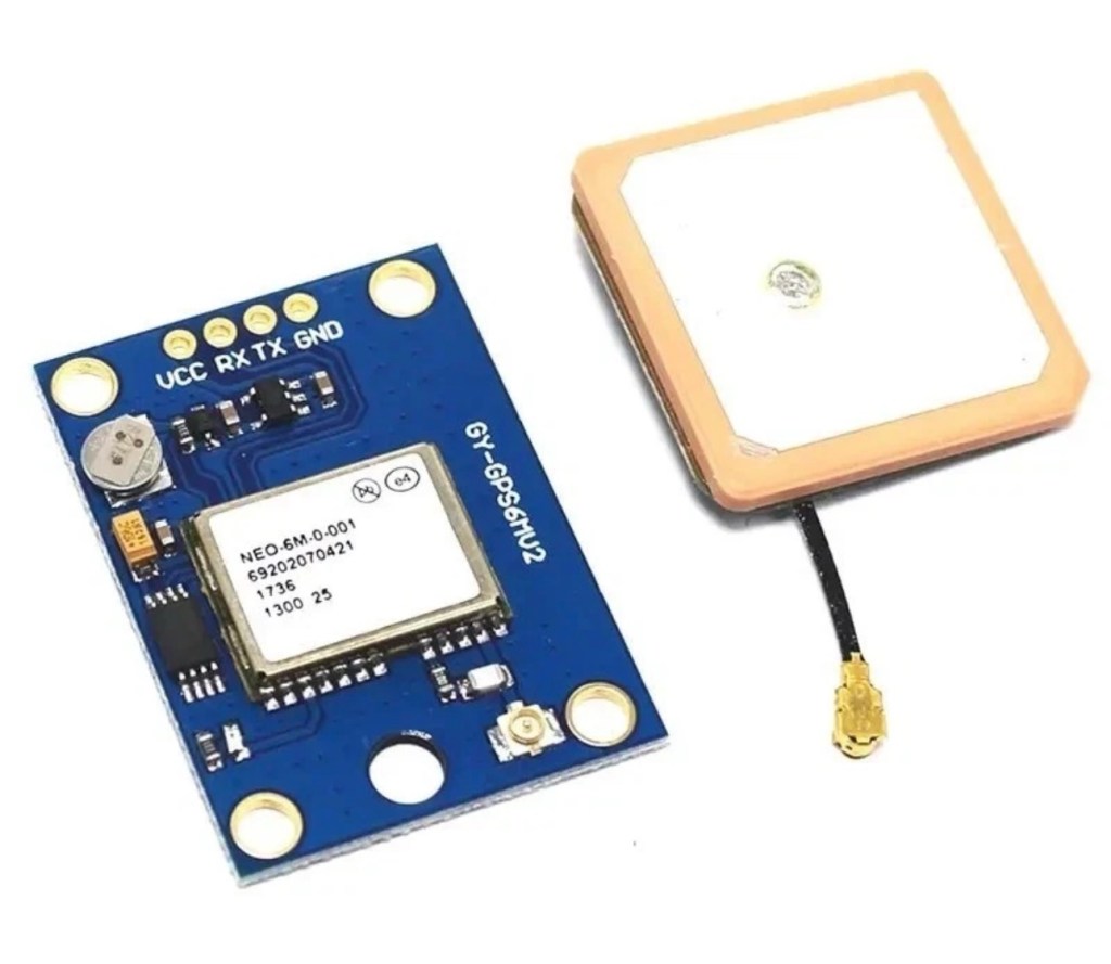
I have purchased the separate GPS module, and I will have to do some soldering to get this working. It will not fit in this case as I have already stated, so that upgrade will be saved for a later post.
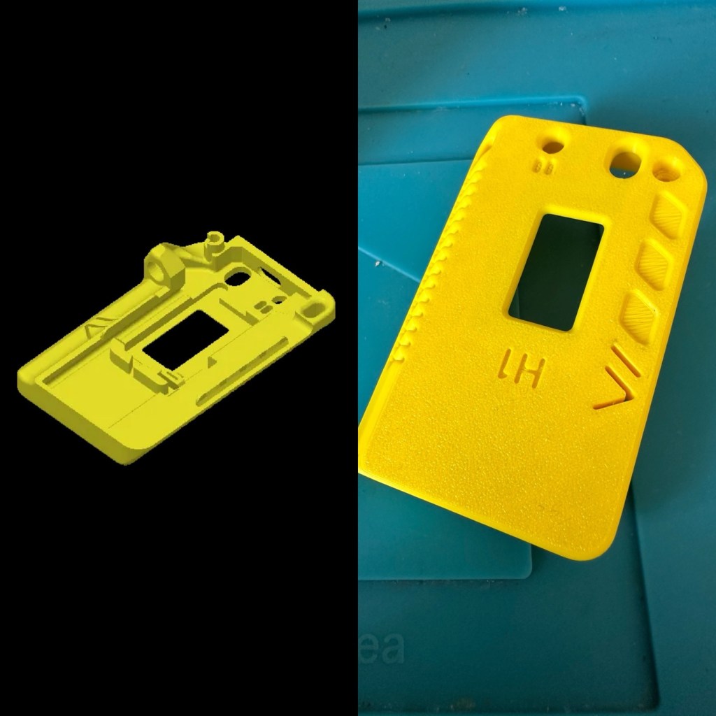
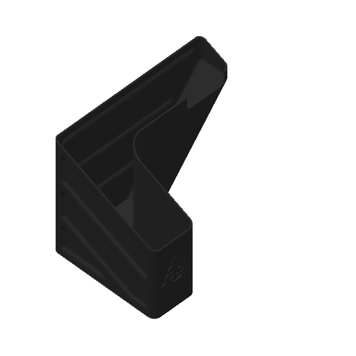
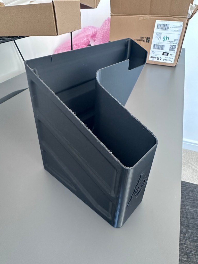
I want a basic slightly different colour scheme for my case, and below you can see a combination of pictures showing the original print plans and what the final piece looked like. It’s a three piece case, and I had to print this case on three different runs to get the different colours.
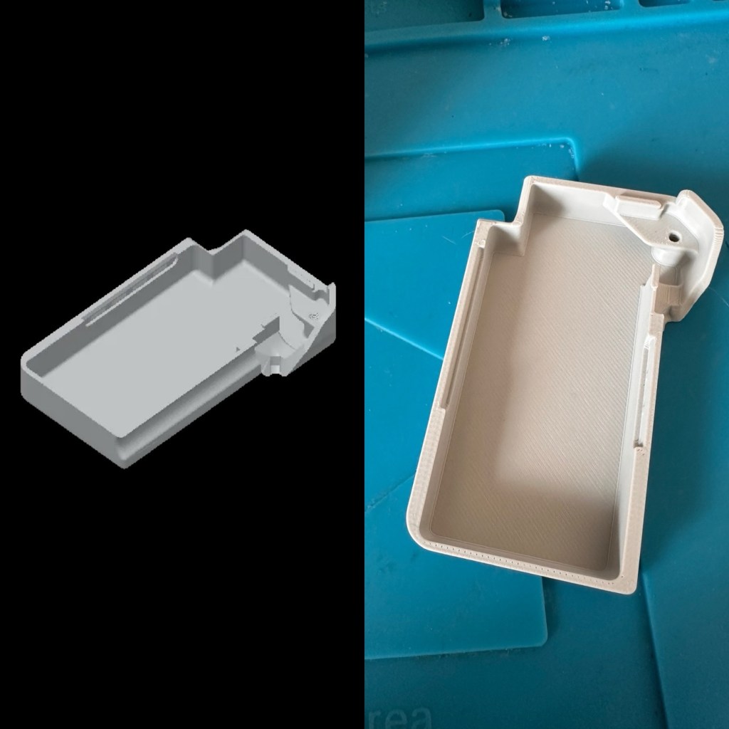
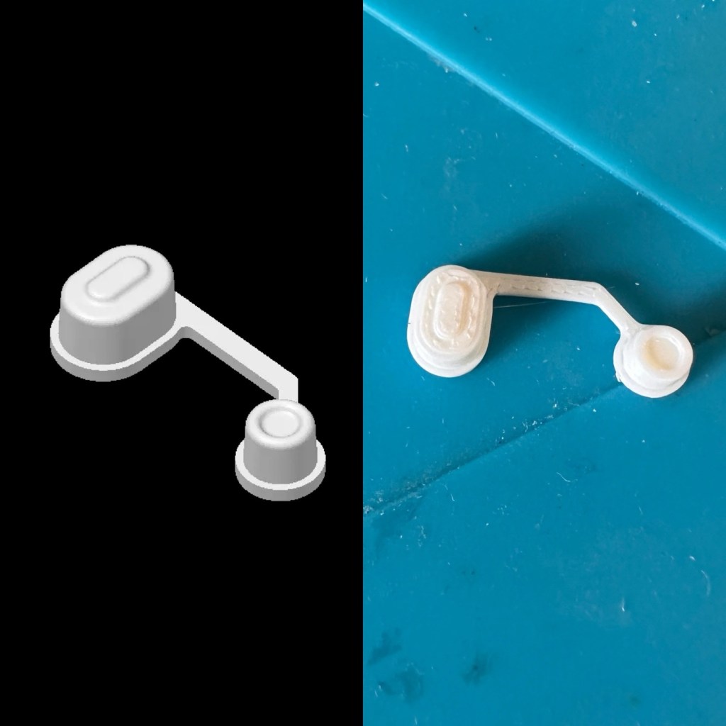
The finished case has been assembled I now just need to await the arrival of the kit for its installation.
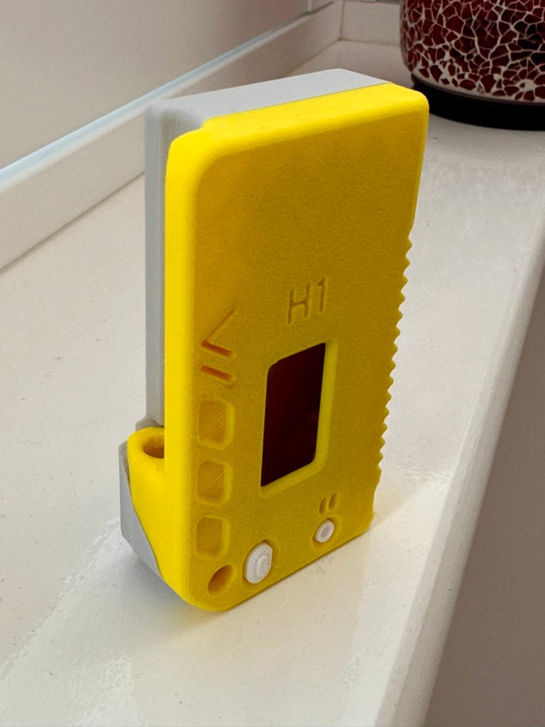
For those of you who haven’t referred back to my original post, here’s a very brief description of what Meshtastic is all about, there are also other choices and platforms to operate with using Meshcore and Reticulum as examples, so here goes….
Meshtastic is an open-source project that allows you to build decentralized, off-grid text messaging and GPS tracking networks using small, inexpensive LoRa radios. Operating on license-free frequencies, devices link together as a “mesh,” automatically passing messages from node to node without relying on cell towers or the internet. In the Uk Meshtastic operates on the 868Mhz band.
Because they are walkie-talkie style text networks, they don’t support voice or video, but they are fantastic for hiking, emergency preparedness, or team coordination.
Other Off-Grid Mesh Options:
If Meshtastic doesn’t quite fit your use case, there are several alternative protocols and ecosystems built on the same underlying LoRa radio technology:
- MeshCore: A rapidly growing alternative. While Meshtastic acts as an “ad-hoc” network where every device handles forwarding, MeshCore allows administrators to set specific device roles like stationary repeaters or personal companion radios. This reduces network congestion, making it highly reliable for structured urban networks and tactical operations.
- Reticulum: A highly advanced, open-source stack built for extreme conditions and censorship resistance. It is more modular than Meshtastic and supports multiple types of underlying hardware (not just LoRa), but it has a much steeper learning curve.
- GoTenna: A commercial, plug-and-play solution. Unlike the DIY nature of Meshtastic, GoTenna pairs pre-built, proprietary hardware directly with your smartphone app. It’s easier for beginners but lacks the massive community, range expandability, and customization of open-source projects.
- Amateur (Ham) Radio / APRS: If you are willing to get a license, Automatic Packet Reporting System (APRS) operates on designated VHF/UHF frequencies. It allows you to send text messages and GPS beacons over vast distances using commercial handheld radios (like those from Kenwood or Yaesu) via established infrastructure rather than a localized mesh.
Assembly:
Ok. This isn’t that difficult and should be quite straightforward. The thing to remember is that the antenna MUST be attached to the board before power is applied. This is because the unit turns on and starts sending a signal as soon as power is applied, and without the antenna attached these units are renowned for burning out components for such a basically overlooked and simple step in the assembly process.
The whole thing is clicked together in about 5mins flat, the one task that takes the longest is the fastening of the aerial into the case. If you have sausage fingers like me, it can take a little time and a few attempts to ensure you get the screws set up correctly to ensure you don’t double thread the item. Here’s some pictures from unboxing to full assembly.
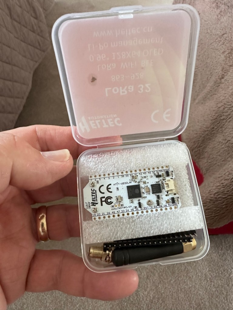
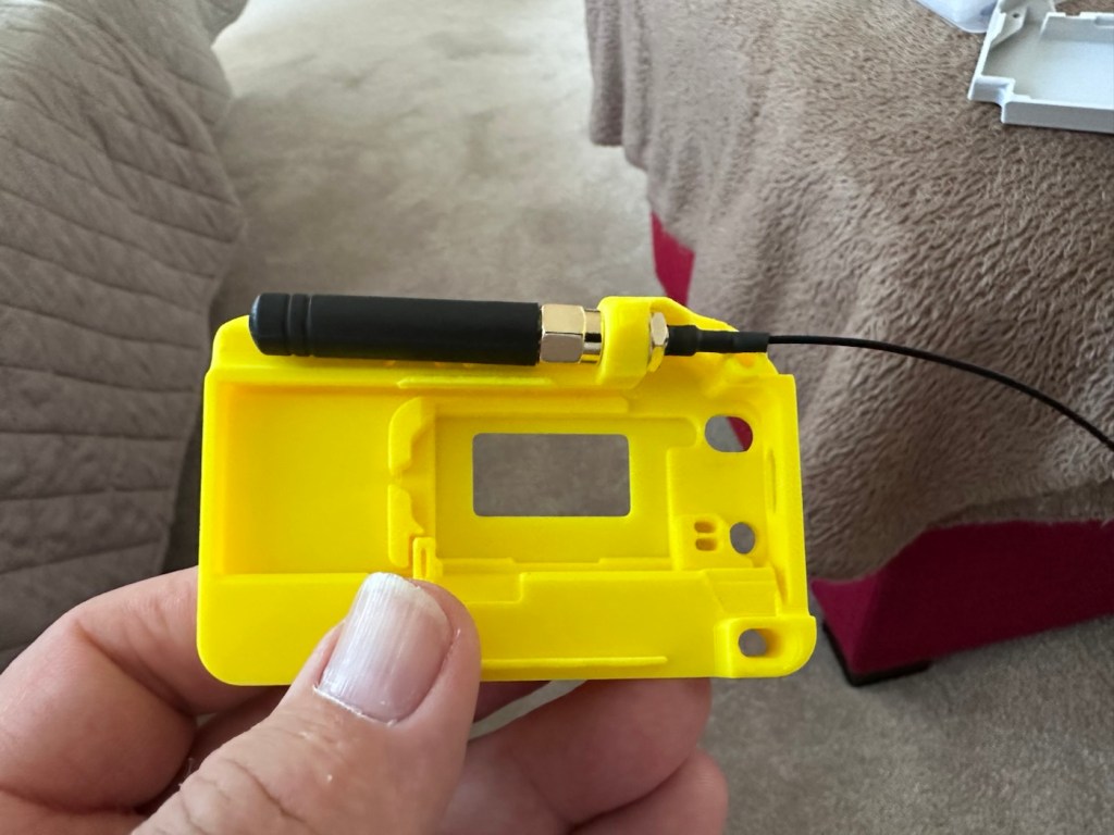
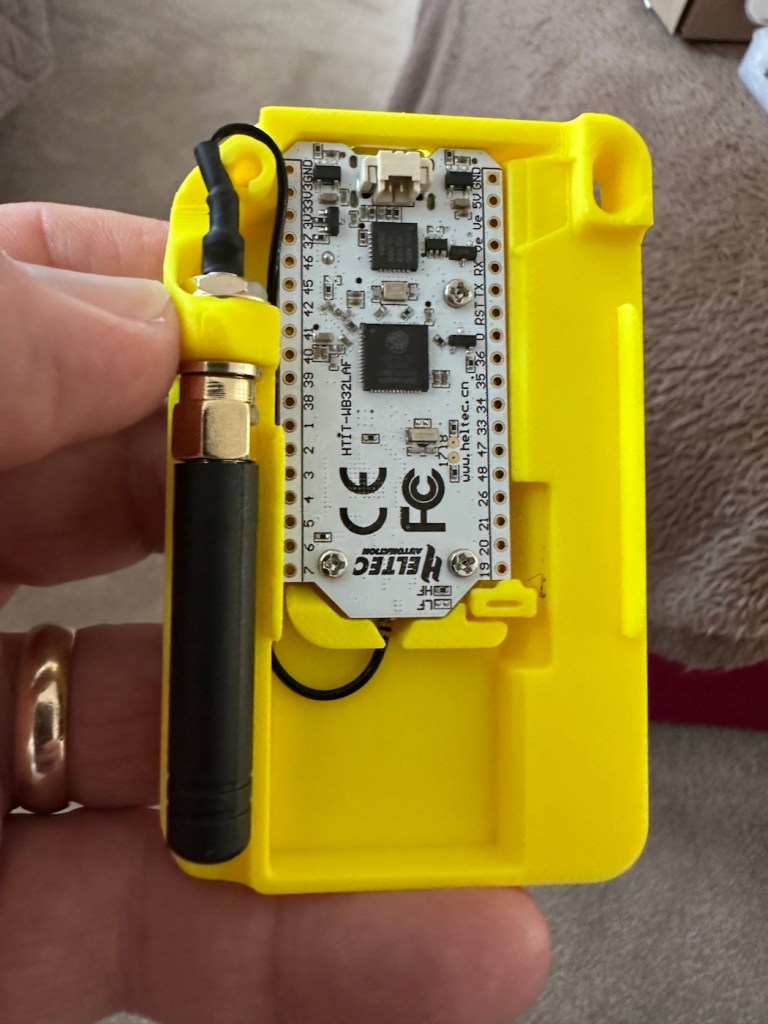
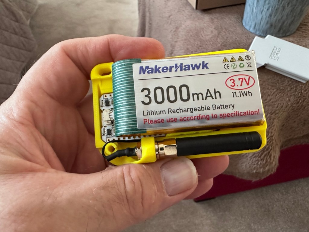
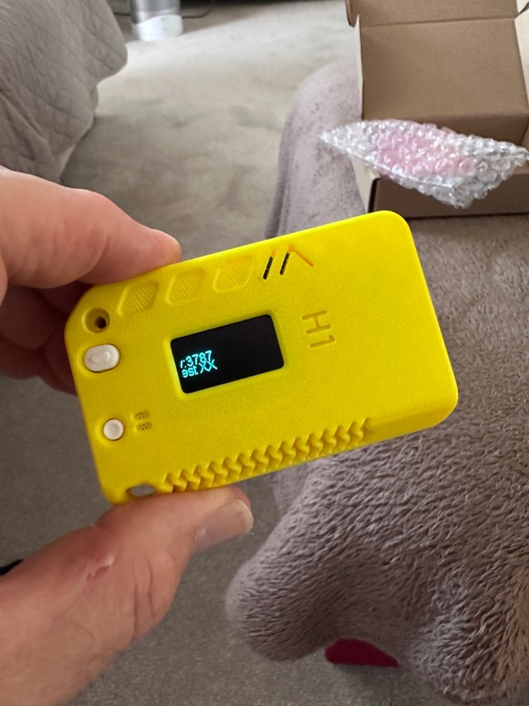
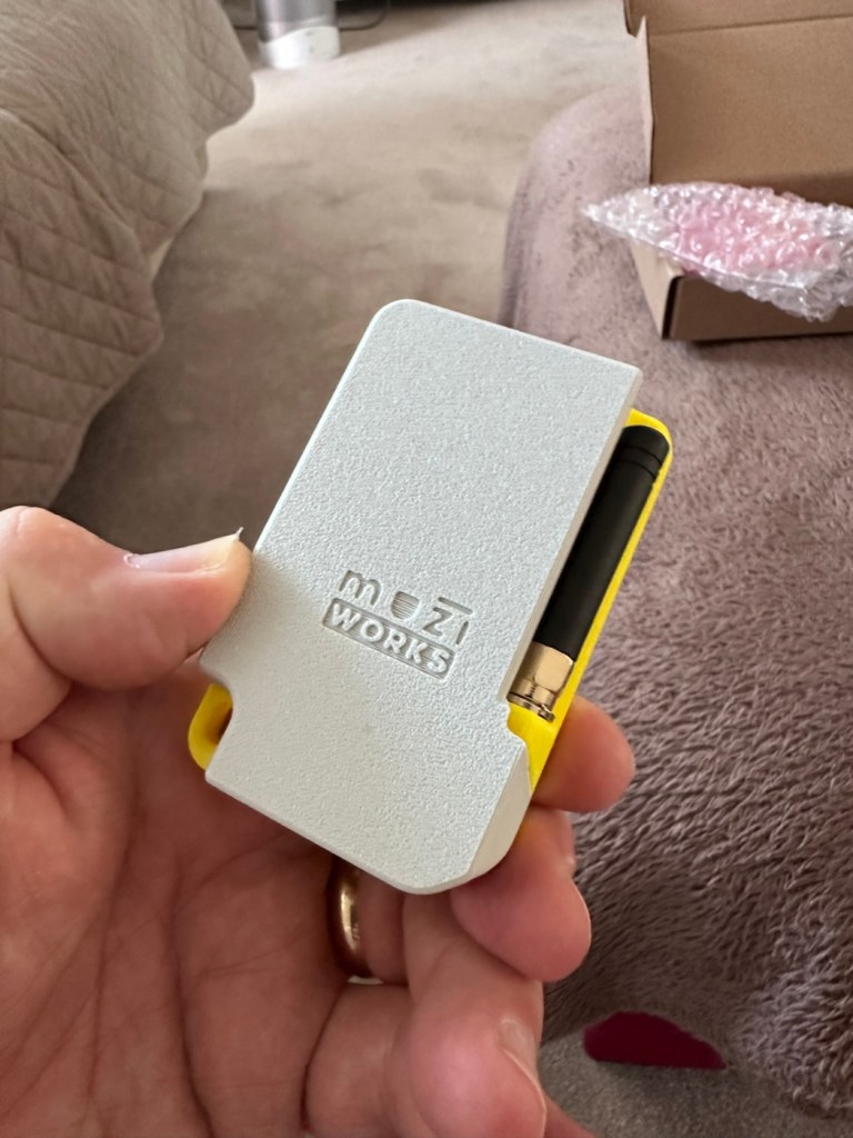
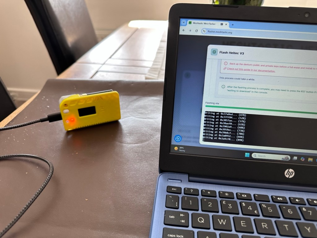
Once assembled the next thing to do is to flash the board with the correct operating software from the Meshtastic website. I’m not going to go into much detail with this as there are many good instructional videos out there that already have this covered, here’s one that I used to get me started:
I’ve been using this node for around two weeks now, just testing its capabilities and seeing what the life span of the battery is. Here where I am in my part of the East Midlands, take up and usage at the moment is quite poor and in fact there is only one other node near me in use, and that one is being used infrequently to say the least. So for me, it’s just a waiting game to see if any other nodes appear as word gets out about the system, and basically if any is interested.
I have only made one contact within that time, a node that is about a mile away, and that’s it. There are so few nodes in my area, I believe i am only the third within a two mile range, and one of those is an unmonitored unit. but at least its a contact and proves the unit is working. It’s early days around here and a better mesh needs to be implemented. I’m sure in time as word gets about, and if anyone is interested that things will improve.
The thing of interest about this method of communication is that it’s purely off grid. Should every other form of communication cease for whatever reason then this is looked upon as an alternative for local “Meshed” communication. It’s a bit of a tin foil hat system in my personal view, I’m sure if someone in a position of power or tyranny wanted to shut the system down I’m sure that they could without too much trouble. It’s a good experimental system in keeping with similar practices that the Amateur radio network adhere to, however this system does not require licensing and is free for anyone to experiment with. And that’s the interesting part.
With the battery charged, and the system active my first “listening” session shows the following:
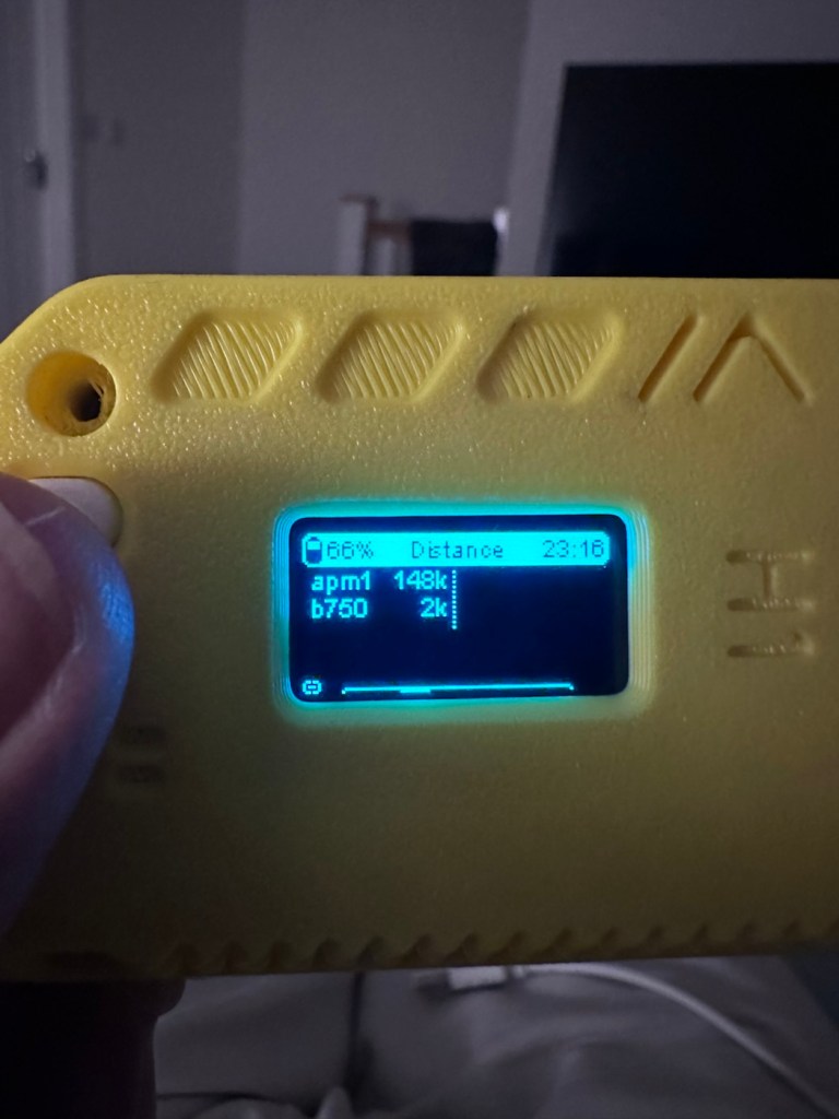
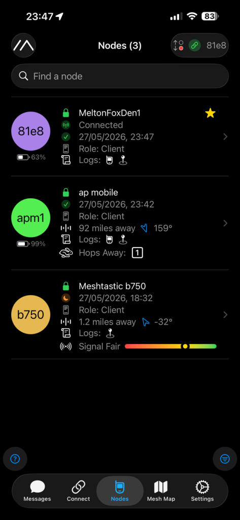
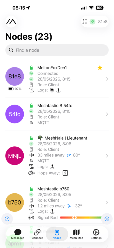
Here is where things become weird, and it’s the point that you realise that others are already stepping away from the true local message usage that was intended to try and make the system a longer range one incorporating the internet as a form of transportation for messages. This makes me scratch my head as surely the internet would be one of the first modes of communication to go down if there was some catastrophic event that took out traditional modes of communication? However, there is this mode that can be accessed called MQTT:
MQTT is a lightweight, publish–subscribe, machine-to-machine network protocol for message queueing/message queuing services. It is designed for connections with remote locations that have devices with resource constraints or limited network bandwidth, such as in the Internet of things (IoT). It must run over a transport protocol that provides ordered, lossless, bi-directional connections—typically, TCP/IP.[1] It is an open OASIS standard and an ISO recommendation (ISO/IEC 20922).
Wikipedia
Anyway, I had this setup, and I’ve now disabled it to ensure two things, that the system is true to its original intentions, and also to get a true idea of battery life using the most basic of setups.
Some things I have noted within the last two weeks are that if you are not in possession of a system with a GPS module, you then have to setup your node with a fixed location. This is absolutely no issue if your node is going to remain in a fixed position. However if you wish to take a node with you and move around, and let’s say you are 200 miles away from home, unless you go into your computer and reset the fixed location then you will always be 200 miles away from home but still showing as being “At home” hence giving false location information and giving anyone local to your new position false hope on them suddenly picking up a very strong signal over a long distance. Pretty much unheard of and impossible considering the power limitations of this system.
So one thing I will now do is attach the GPS module I mentioned towards the top of this post, to get accurate location information whilst mobile. There is a caveat here in that the power drain will be excessive for this battery and the GPS will greatly reduce its capacity.
Currently, with this node sitting in an upstairs bedroom window I am easily getting 24-36hrs from a single charge. Add to that a battery power bank I have with a solar charging capability I’m pretty much getting an almost endless period of usage. Weather has not been what I’d call particularly sunny recently, so I’d suspect capability would be much improved during summer months. I’ll just have to see how well this setup can work with the GPS system installed.
The current case I am using does not have room in it to facilitate the GPS board and antenna. For this purpose I have had to print a new case to house the unit in, and this is the barebones case pictured alongside the original case.
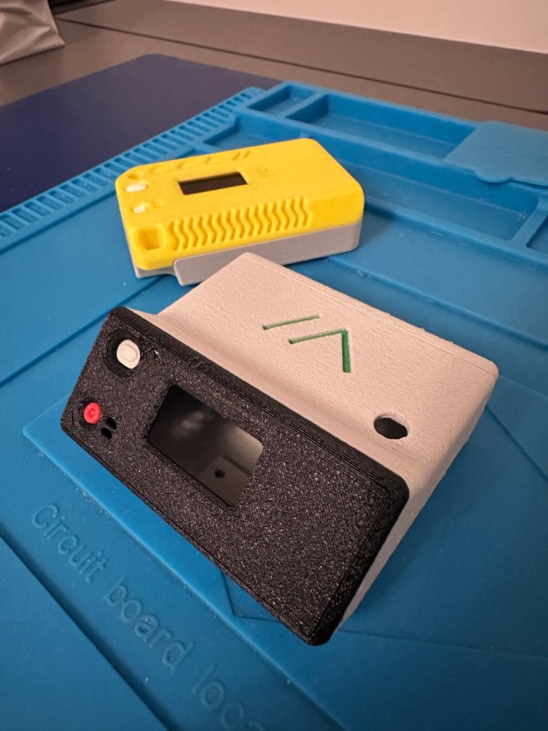
The old case will not be wasted. I intend to use that as a permanent fixed home base that I can use for testing the mobile one, and for building my own personal mesh system at home. The good thing with this system is that as well having public broadcast channels, you can also setup personal private channels for family and friends.
So let’s get the GPS setup.
The GPS board comes as a two part package. One part is the actual main board whilst the other part is the antenna on its own small board with a wire to attach it to the main board.
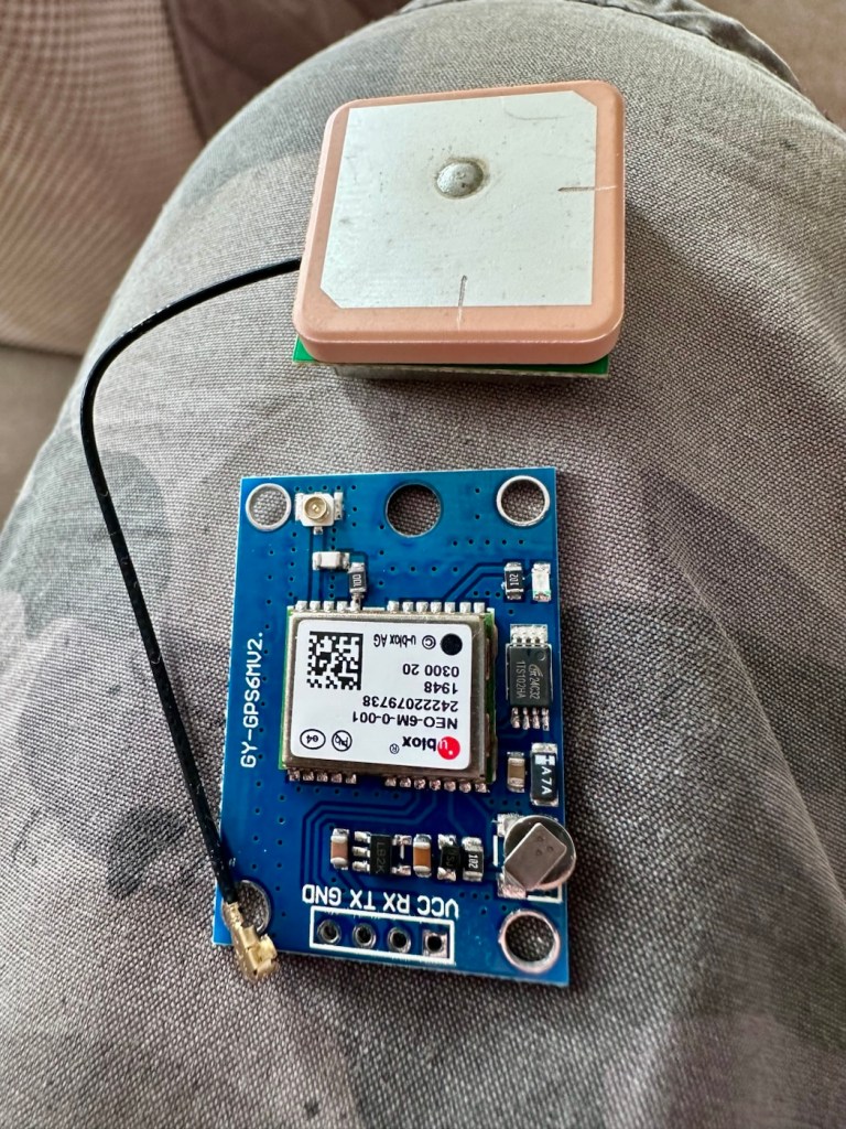
Here is where the fun begins as we are going to have to do some soldering of this unit to the actual main “radio” board.
In a nutshell this little video explains exactly what you have to do.
I’ve had to solder 4 wires that connect the main board to the GPS unit. These are only temporary at this moment, as I need to be able to sit all components comfortably within the casing. I may have to add a switch, however I’m exploring other options at the moment. I’ll get to the reason why in a short while.
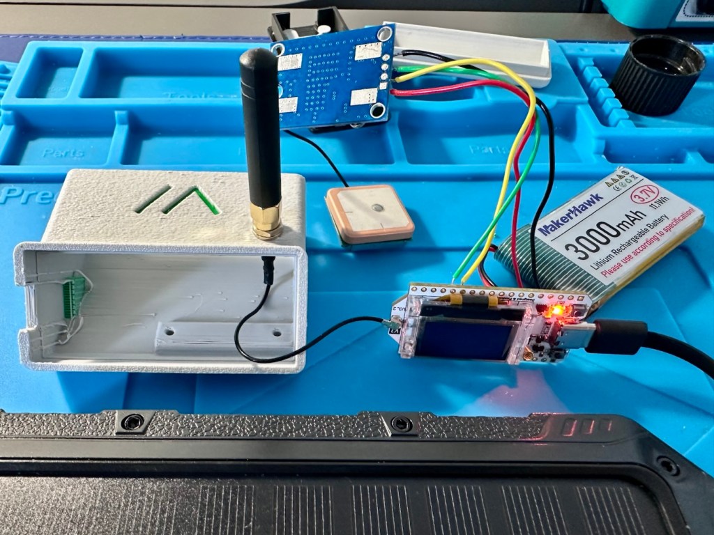
The four wires connect power, a ground, a receive pin and a transmit pin, there may yet be a fifth wire, I’m exploring that option as stated above.
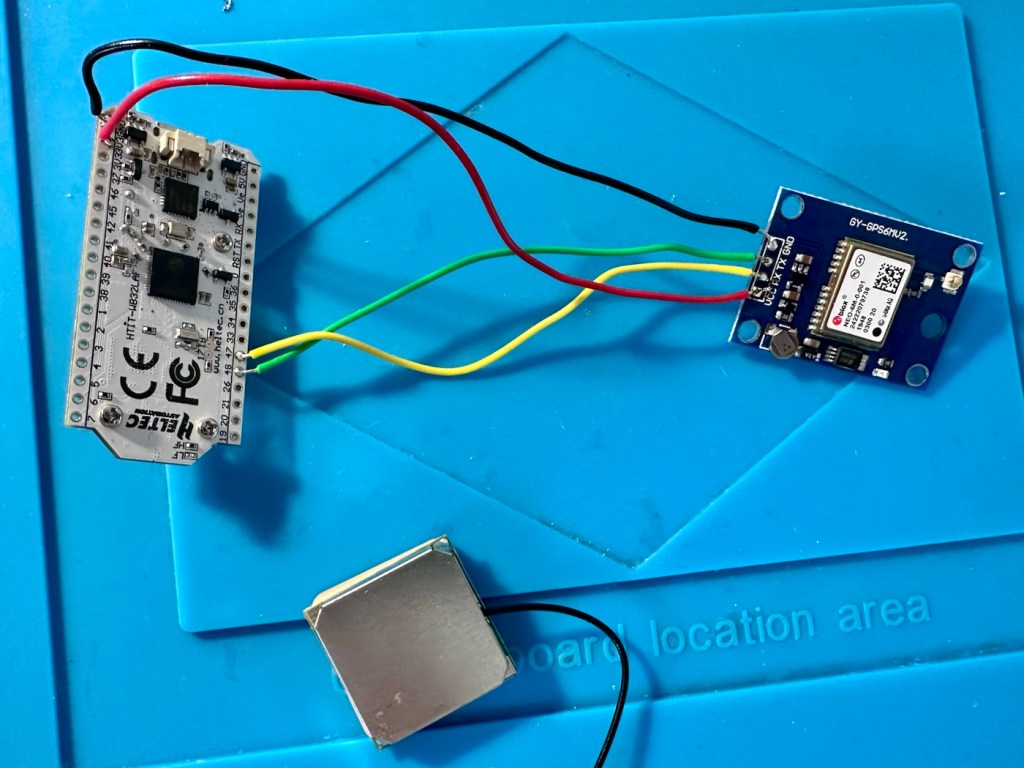
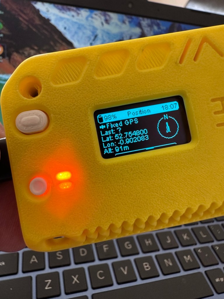
So does this work? I’ve charged the battery up to 100%, I’ve made some changes to the settings within the operating system and have turned the unit on. These system fires up and then a separate blue light on the GPS board flashes indicating that there is power to the GPS board.
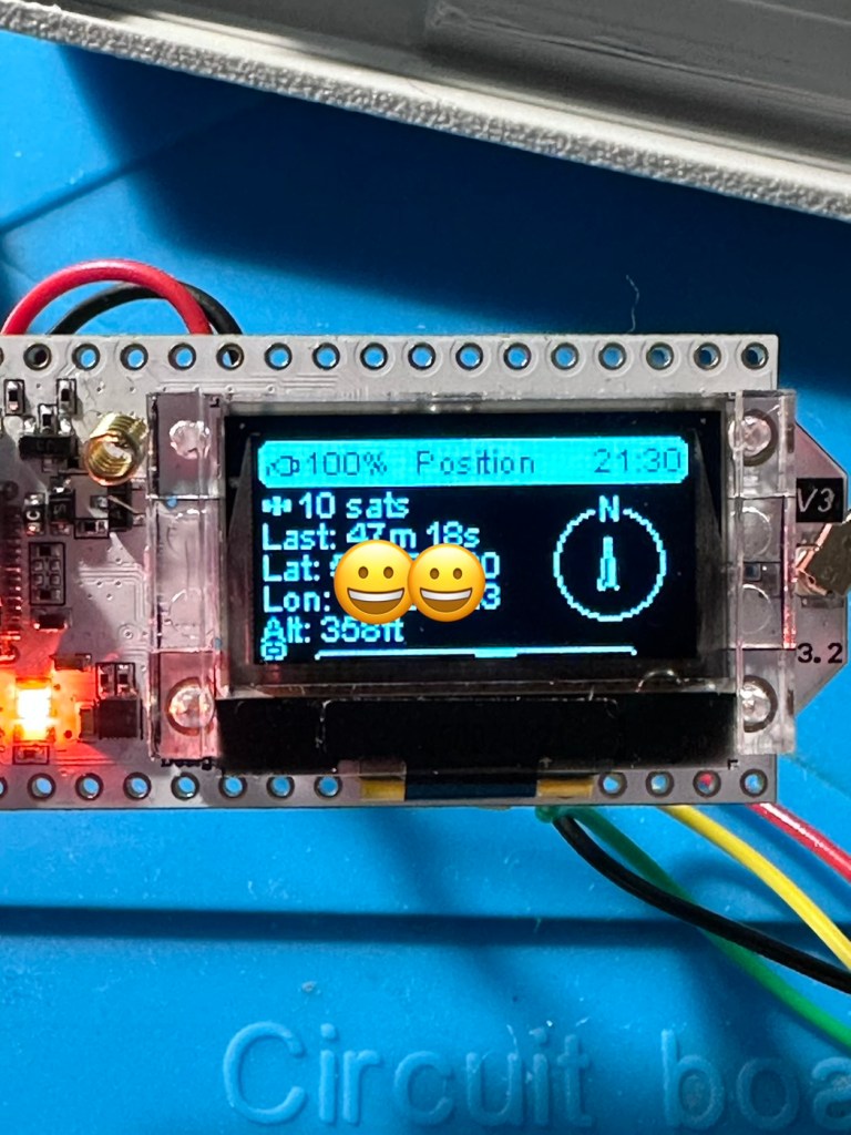
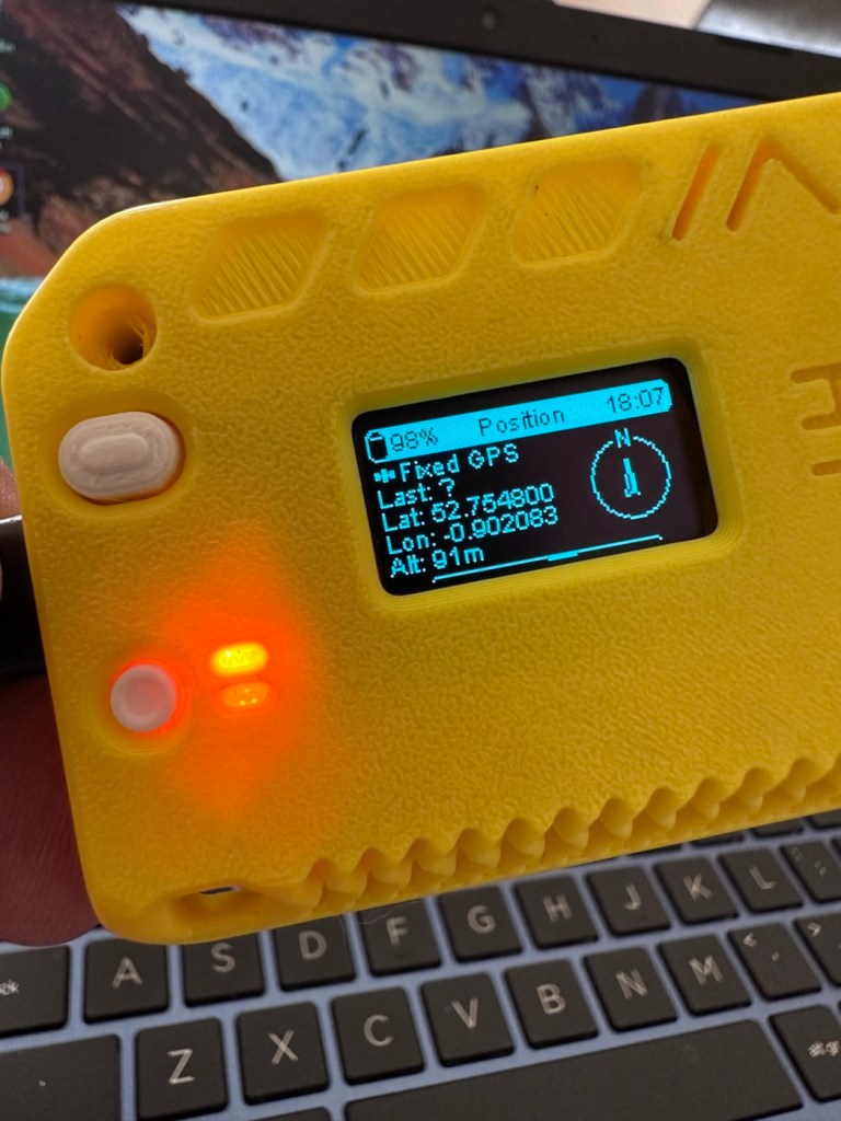
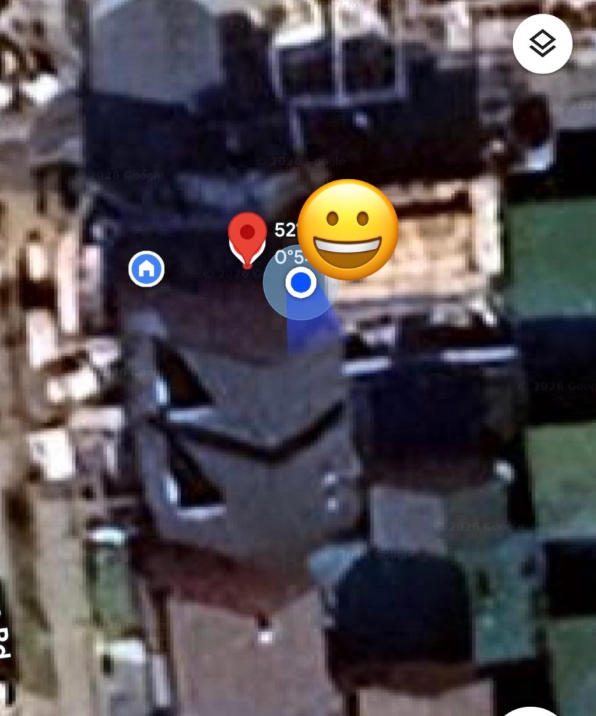
And then there is confirmation of 10 satellites being tracked, a height asl, and a longitude and latitude bearing, all seem to be working. But how accurate is the GPS reading? I put these readings into Google maps and the result is spot on. In the picture below the blue dot represents my phone location, and the red dot represents the GPS coordinates from the GPS module. Working perfectly👌. All smiley faces are just disguising the readings, much that I appreciate your reading of my shenanigans, I don’t have enough tea cups to welcome you all in 😂
Previously prior to the addition of the GPS module I did state that I was easily getting 24-36hrs of life out of this battery on a single charge. That is going to change quite significantly as the GPS module is a super power hungry beast. I’ve currently set the GPS module to transmit its position once every hour. To be honest I could probably transmit once every 8-12 hours as i am currently in a fixed position and not moving. If I were in a car, I might even look at transmitting the coordinates every two minutes as this appears to be the default setting for a mobile node, and that would certainly drain the battery in no time. It would probably be best practice in this situation to have the unit running on power as the car is moving.
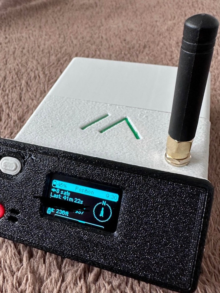
But I’m sticking with the hourly setting at present, just to do a basic drain test. This battery was on a 100% charge setting at 21:30hrs this evening as you can see in the photo above, I want to see if it will still have power 12hrs from now. No doubt power will deplete a lot quicker with the GPS module in place.
Depending on the results, this will help me decide if an extra wire or component or even both is needed within the circuit, and the reason for this is to be able to disable the GPS signal when not required. This modification in its simplest form can be as simple as putting a switch in the 3v supply wire, or by including a MOSFET (an electronic signal switch) into the circuit to allow the main board to automatically turn the GPS on and off via settings built into the software. I’ll make my decision when i see the results after I rise in the morning, and also depending on having the required components somewhere within my spares boxes.
About 7am the following morning (Approx 10hrs after setup) the power level is sitting at a comfortable 50%. The last GPS broadcast was at 02:37 in the e morning, I don’t know why this was as it’s set at a one hour cycle, I’m not complaining, maybe it didn’t have a successful signal to lock on to? Who knows. I have to take my wife out on an errand at about 07:30 so I’m going to put the GPS signal to a two minute cycle, put the bare bones set up on the parcel shelf of the car and just see if it works.
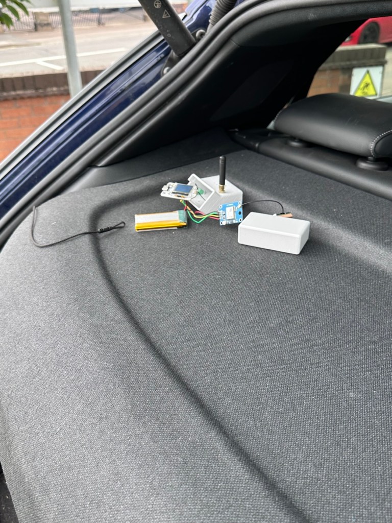
And it has worked perfectly.
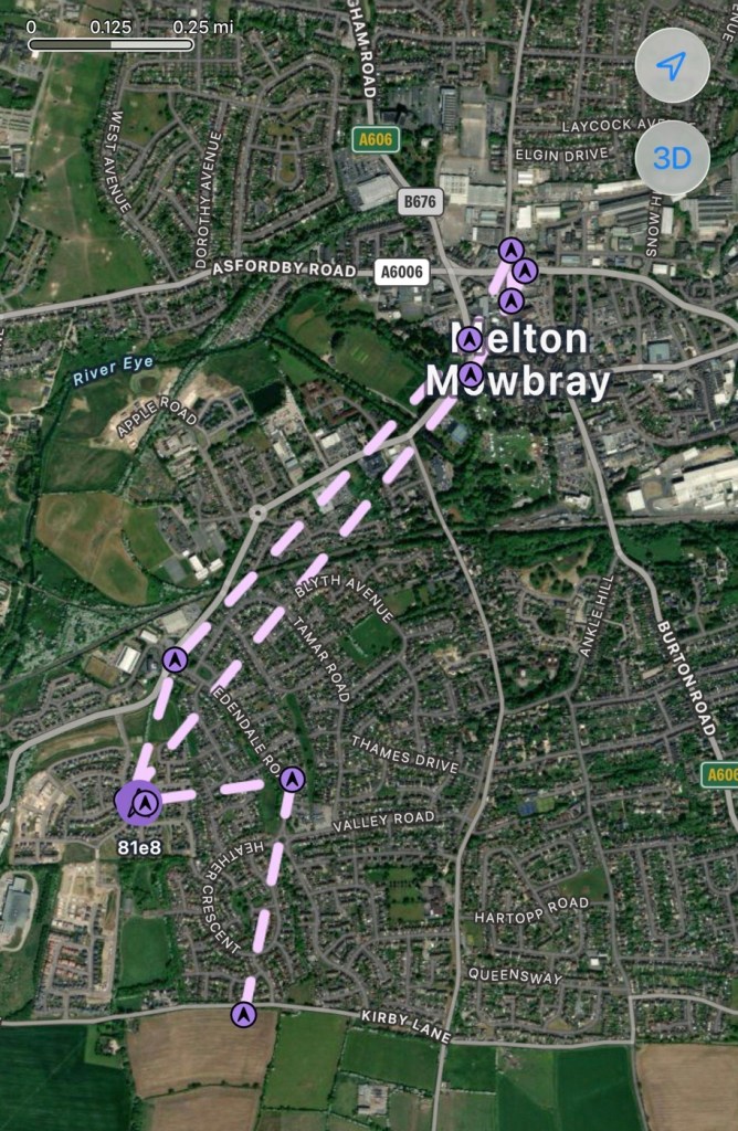
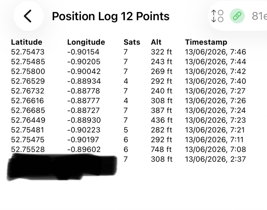
In the GPS log above you can see how it has performed. The received data at 02:37 in the morning was the last on the hourly cycle, and then at 07:08 was the first of the two minute cycle prior to me switching it back onto a one hour cycle again at 07:46. I’m now going to leave it alone until we reach the 12hr mark and I’ll see how this small trial has gone during this period.
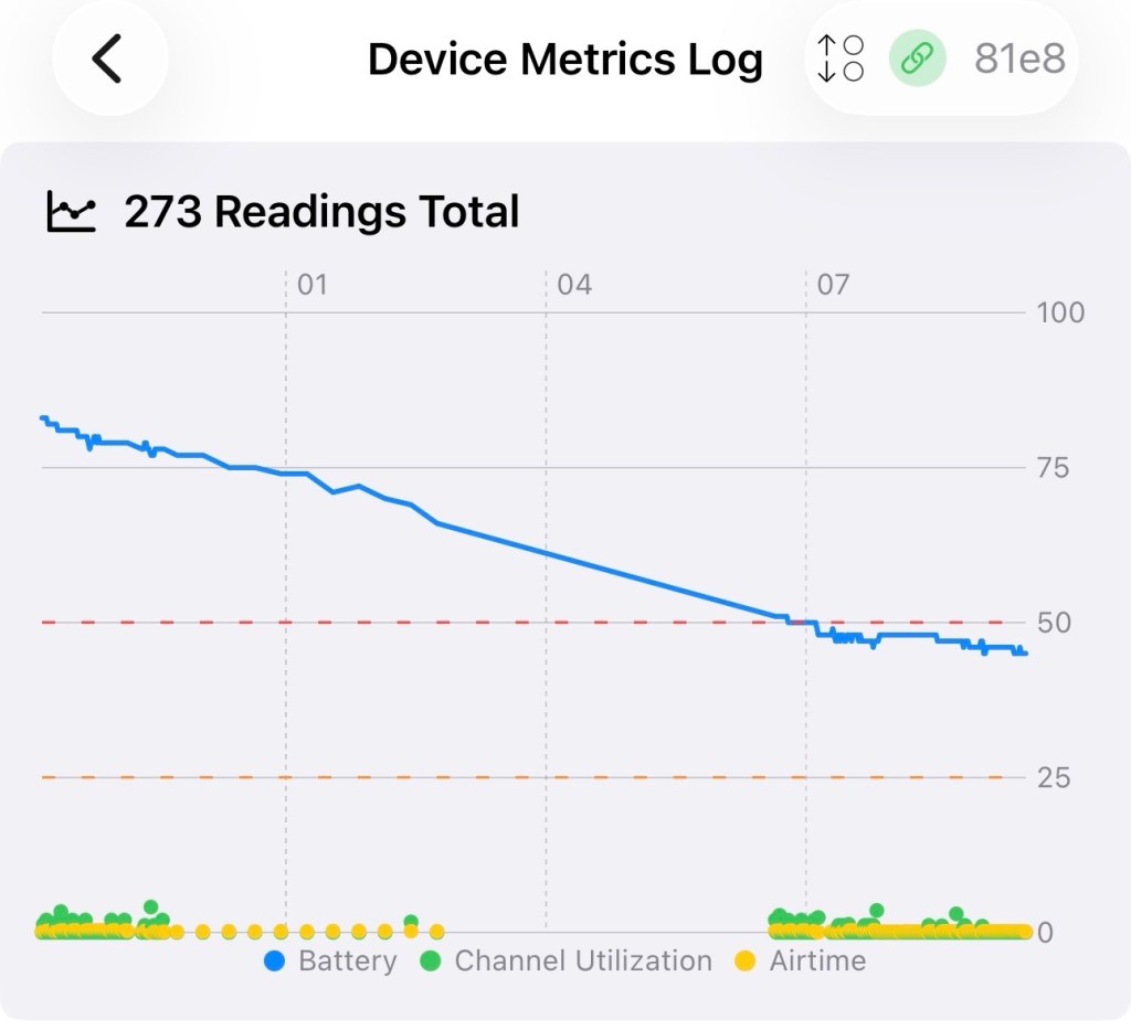
We’ve reached the 12hr post, and the power level is 45%. So over the 12 hr monitoring period with the GPS on a one hour cycle we have used 55% of the battery capacity.
If you look at this log of the diagnostics over this period you will see a gradual decrease in battery capacity (Blue line) with the only noticeable disturbance being when I turned the GPS to a two minute cycle at 07:08 this morning when I had to take my wife out.
Overall it’s a pleasing result but I’d suspect even with a low usage of the GPS module I’d probably only be able to get 18hrs of usage maximum from a single charge using the GPS on a one hourly cycle. Using the 2 min cycle I’d probably struggle to get 12 hrs of use from a charge, maybe even less, compared to the normal battery life of 24-36hrs without the GPS module you can see that the difference in power consumption that is involved. As I have said previously the GPS is quite a power hungry addition.
But do you know what? The figures are pretty good to be honest. If I use the unit at home I will reduce the GPS signal to probably one cycle every 3-6hrs. If I’m out mobile I very much doubt I will be driving more than a few hrs maximum, so I can always switch cycle rates as required.
So. Do I need to add another cable or that MOSFET discussed earlier? Probably not, it’s not essential but sometimes it may be advisable or recommended to maintain anonymity so a switching system would benefit in those situations.
For the meantime I’ve just thrown the bare bones unit into its case with no proper spacing, as I’m going to take the unit out again today on a slightly longer journey for a family gathering. It will be good to see how it performs and to see if we can get any noticeable contacts in an area other than my home location. You never know that Meshtastic may have a greater following or uptake in that area.
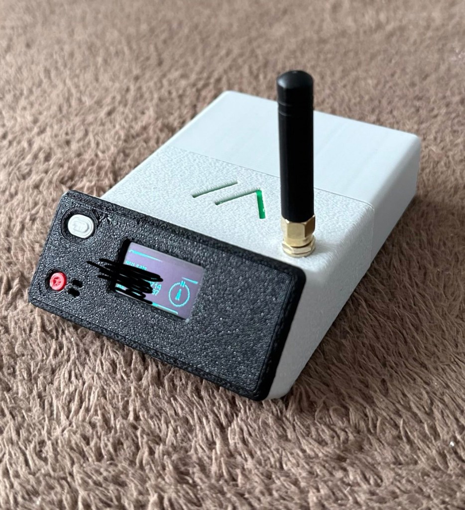
And the journey out to the family gathering registered just fine. I’m confident and happy that the GPS addition has been successful.
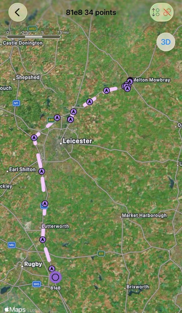
And guess what. There are even fewer nodes in use to make contact with here. I am, or appear to be the only one, it’s a lonely pastime at the moment.
The journey back home was fine and again the GPS worked as it should. Now to get the GPS power management installed, I’ve decided to go with the “N” type MOSFET option, I’ll get this installed, tidy up the wiring and get the case placement sorted. I’ll then just reflash the software to remove any glitches and then I will rename this node as my mobile option – (MeltonFoxMob – MEFM). I’m then going to get myself a second node to build and install, probably a solar node, that will become my permanent home installation node.
I’ve just purchased a couple of N type AO3400a Mosfets as I don’t have any in my spares box. Putting this in circuit will allow me a greater control of the power consumption via the units firmware.
It’s been tested over approximately 6 weeks now and to be quite honest, I’m not that impressed. There has been one single contact over that period, however the vehicle tracking option is ok (ish) there are some questions about the system turning itself off about half way in to a longish journey, but that could be down to me not having the MOSFET in place.
I personally think it’s a fad thing until it really takes off. I will keep my mobile unit and possibly a home unit in place to see just what happens. There is only one node working in my immediate area and I’m not even sure if that is monitored in any way.
These kind of systems have to start somewhere and they just need a few more people to pop on board and spread the word. If I turn mine off then it’s another potential possibility for the advancement of the technology that will have disappeared. I’m going to be persistent with it for the foreseeable future and hope others come on board. But at the moment I’m not overly impressed. Things can only get better as they say.
Thanks for passing by. It’s always most appreciated.





 Foxes Den
You must be logged in to post a comment.