

What the listing stated:
It has not been tested but outside case is sticky.
Would recommend for spares and repairs onlyEBay
Not one of the finest quality camcorder cameras out there, but for £7.00GBP, I’m not really complaining. This camera appears to have a battery included, it has no charging equipment or anything else included, but I’m hopeful there’s not too much badly wrong with it. However as this is a platform for repairing old knackered equipment, hopeful there is something that we can get our teeth into that is sufficiently suited to this platform. All I can currently gather from the listing is that this a bit sticky, and those of you who follow this site will know that stickiness, especially on cameras is not an issue that has caused me any problems previously. Hopefully the issue is a little more than just stickiness, and as this listing has the classic EBay “Get out of jail free – seller not tested” claim, then there could be absolutely anything and everything wrong with it, we will just have to wait and see.
Here’s a little bit of background for this camcorder.
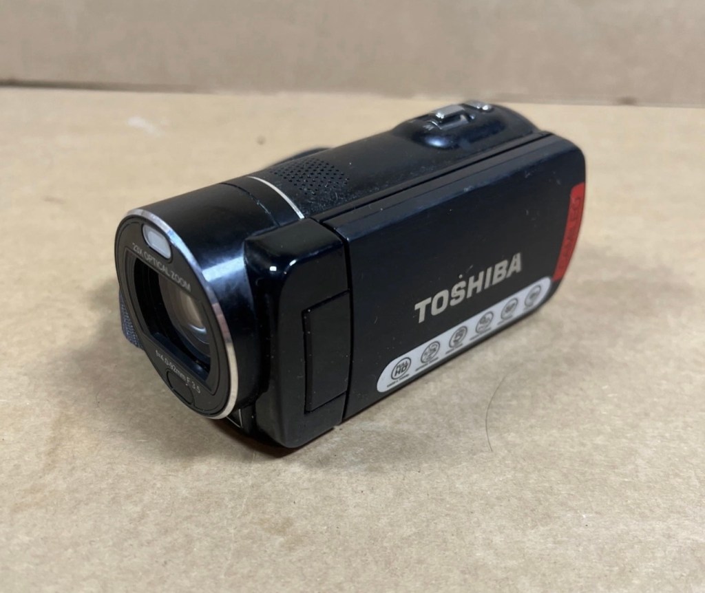
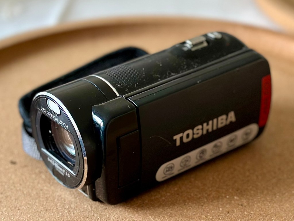
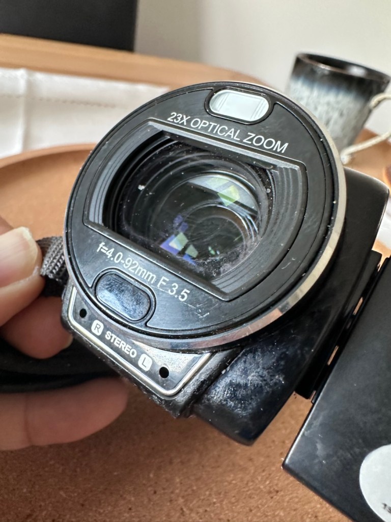
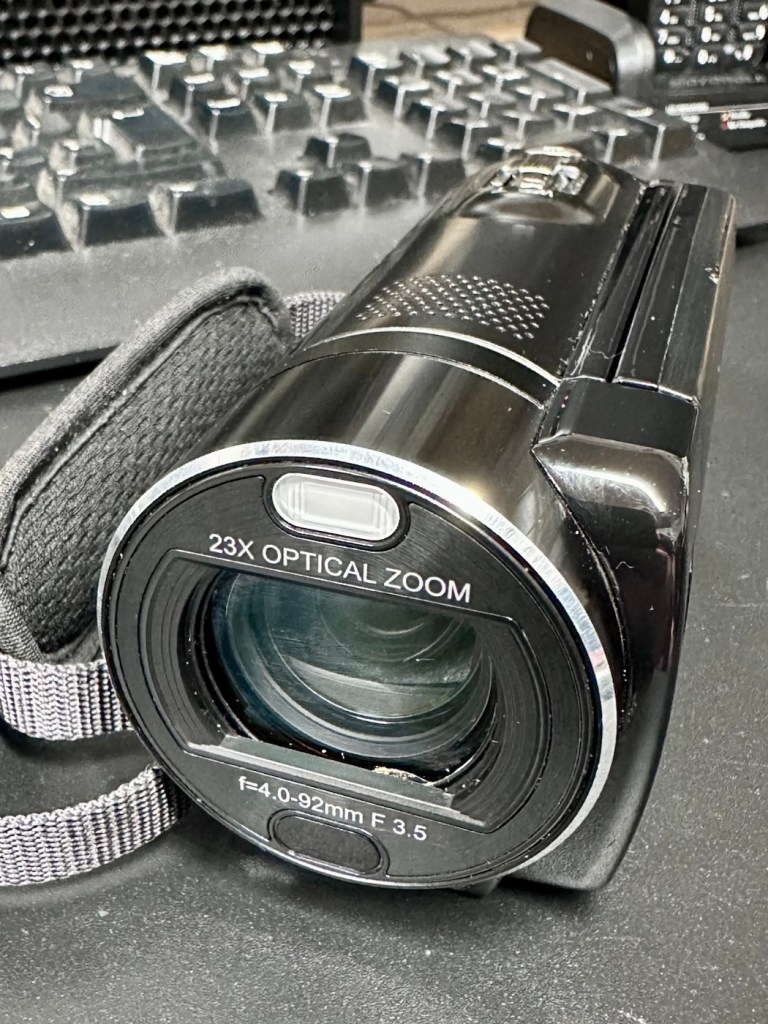
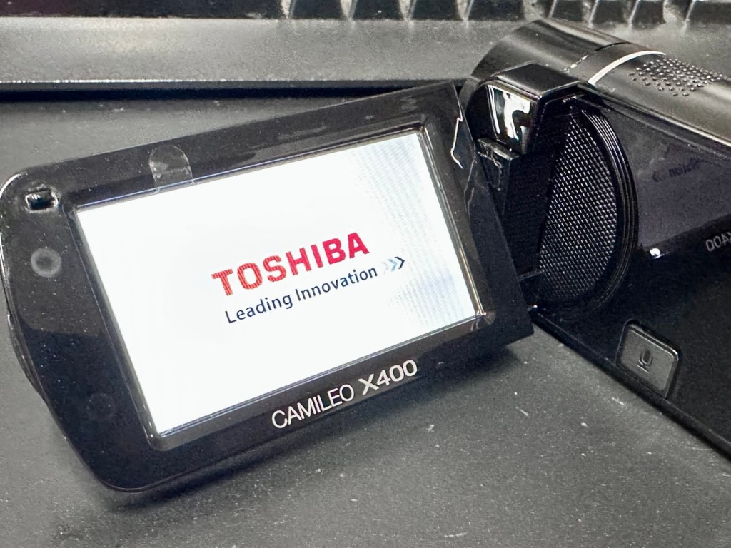
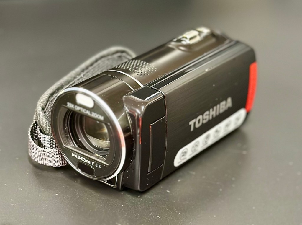
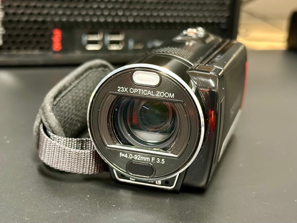
Toshiba’s CAMILEO X400 Full HD camcorder offers 1920 x 1080p video capabilities, 23X optical zoom, and other great features for taking great video and making great memories.
No matter what you’re looking at, the CAMILEO X400 Full HD camcorder takes jaw-dropping video in 1920 x 1080p resolution. You’ll be able to capture all the color and clamor of that Fourth of July parade, or your daughter’s first soccer goal. And with the 23X optical zoom, you’ll see the big smile on her face, too.
Want to follow your baby as she takes her first steps? Follow your friends as they head up that mountain trail? Record your Jeep ride across Africa’s Serengeti plain? Go for it. The image stabilization capabilities on the CAMILEO X400 Full HD camcorder ensure your ensuing creation will be hunky-dory, not herky-jerky.
Video trimming on the CAMILEO X400 Full HD camcorder makes editing easier by letting you cut out a section of the video from the front, back or both–plus start and end the video at any point you wish. What’s more, with a built-in pause button, you can stop wasting storage space and reduce file clutter by recording multiple scenes into a single file.
Your son just learned to surf and caught a nice point break for a good long ride. Want to freeze the frame for pictures you can share in an album, email or hand out to friends? Do it without interrupting the video. Simply press the Photo button* on your CAMILEO X400 Full HD camcorder and your surf dude will be immortalized forever.
Features:
- 1920x1080p Full HD resolution video
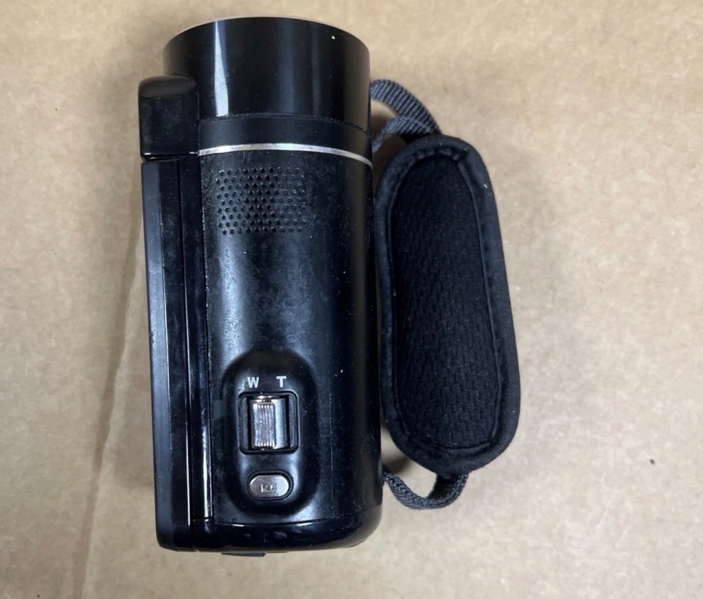
- 23x Optical zoom
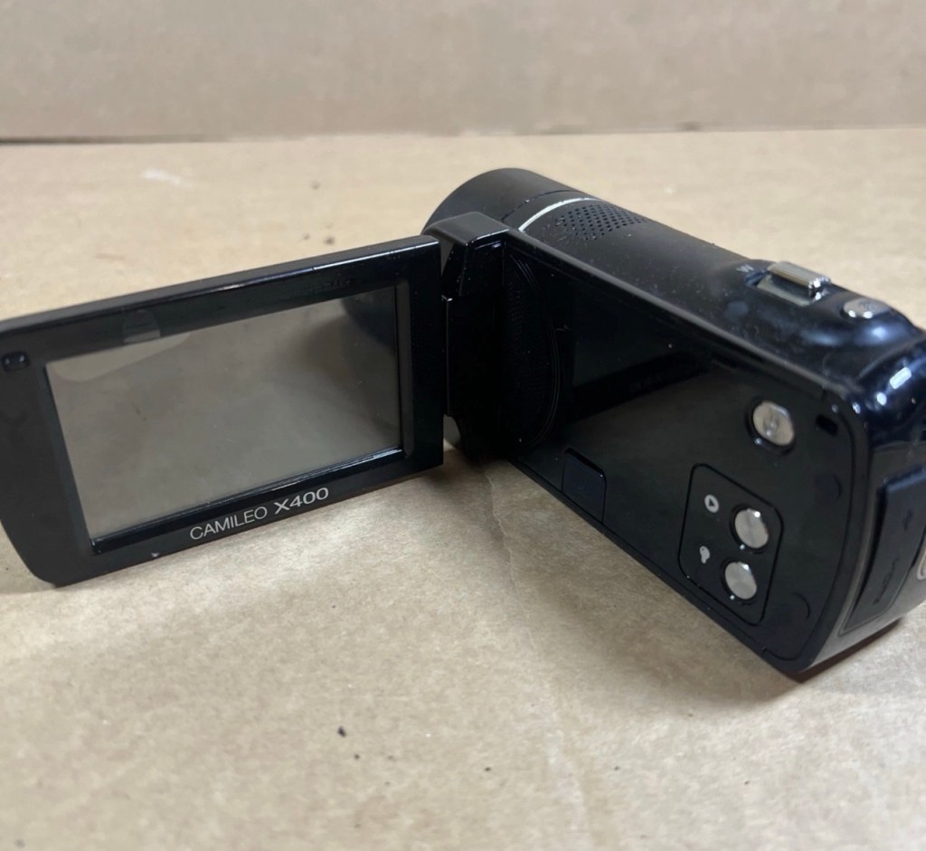
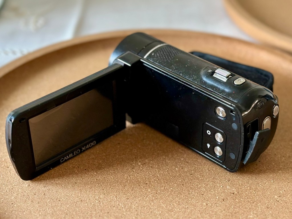
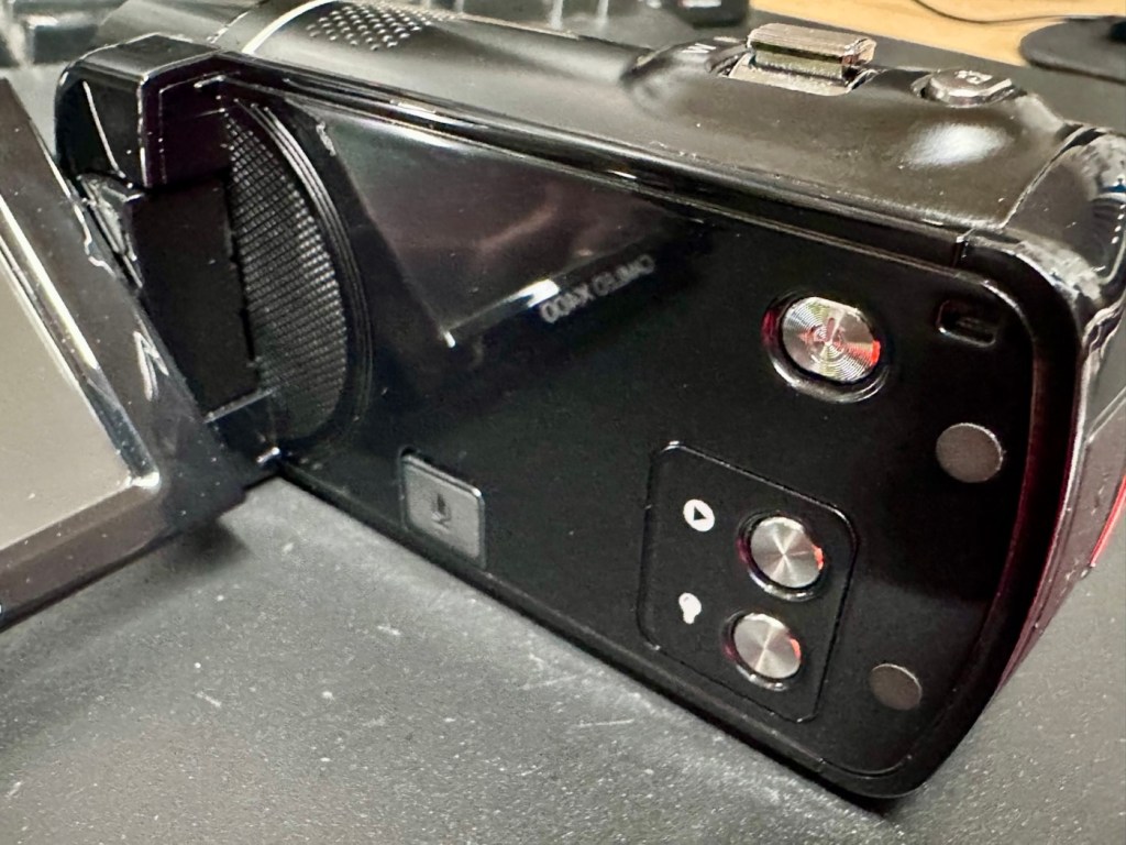
- 3″ swiveling LCD monitor
- 5MP CMOS sensor
- 4.7 x 2.1 x 2.4 inches
- Weight 300g
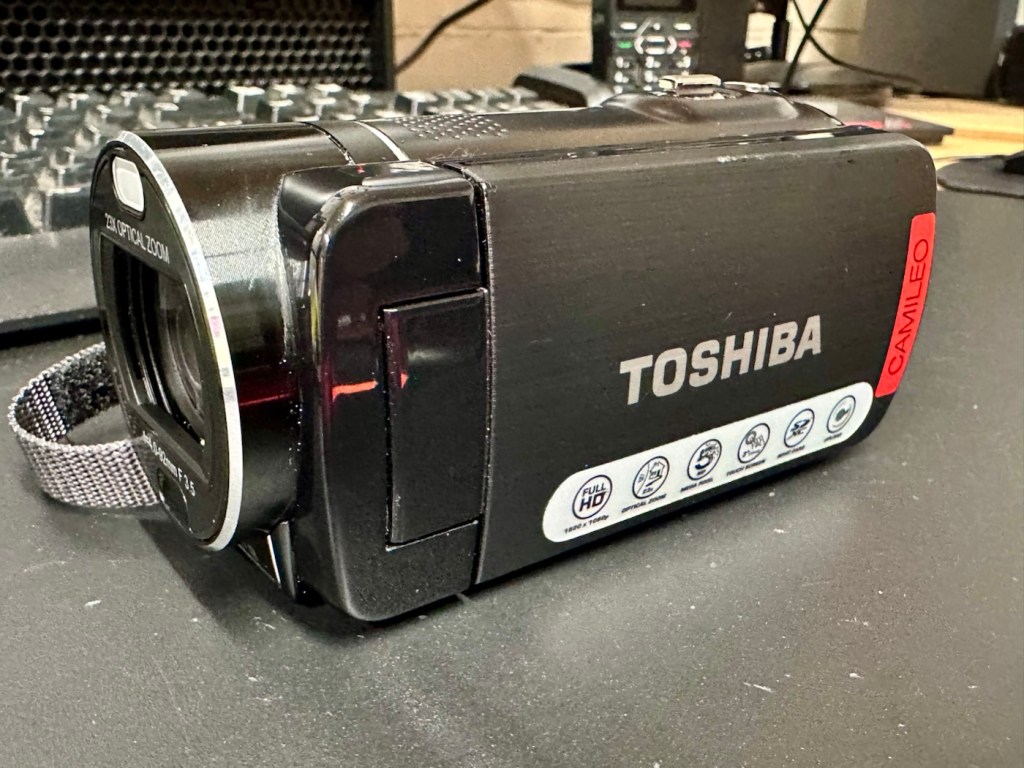
Toshiba
Well, to be honest that has to be one of the worst background write ups I’ve read, and in reality the tone of it doesn’t fill me with confidence, all that talk of “Dudes” and “Hunky dory and Herky Jerky” my god, who do they let write this stuff? This camera didn’t stand a chance to be honest right from its release date in late 2011.
So, let’s forget the awful promotional write up, and just like true “Dudes” try to find out what is actually wrong with the damned thing.
Assessment:
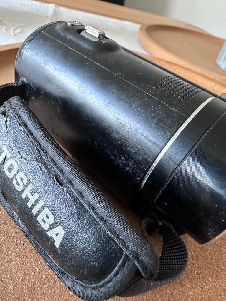
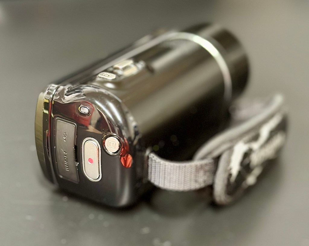
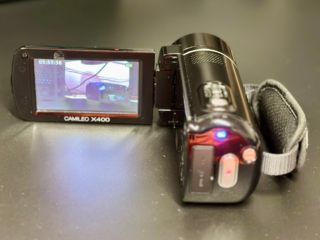
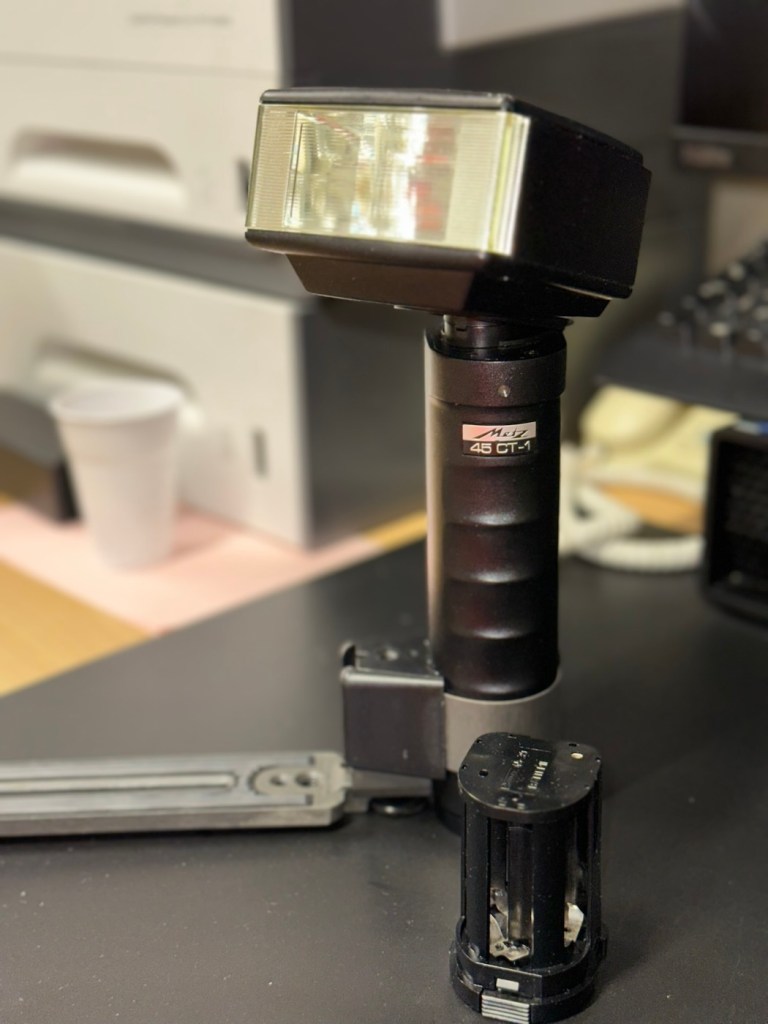
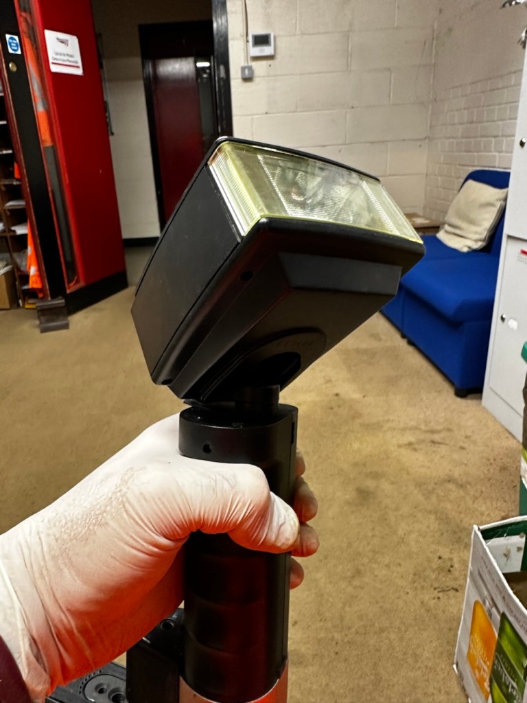
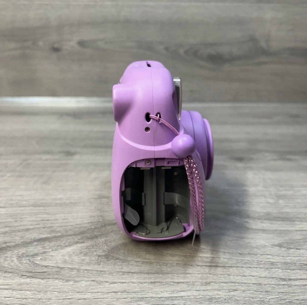
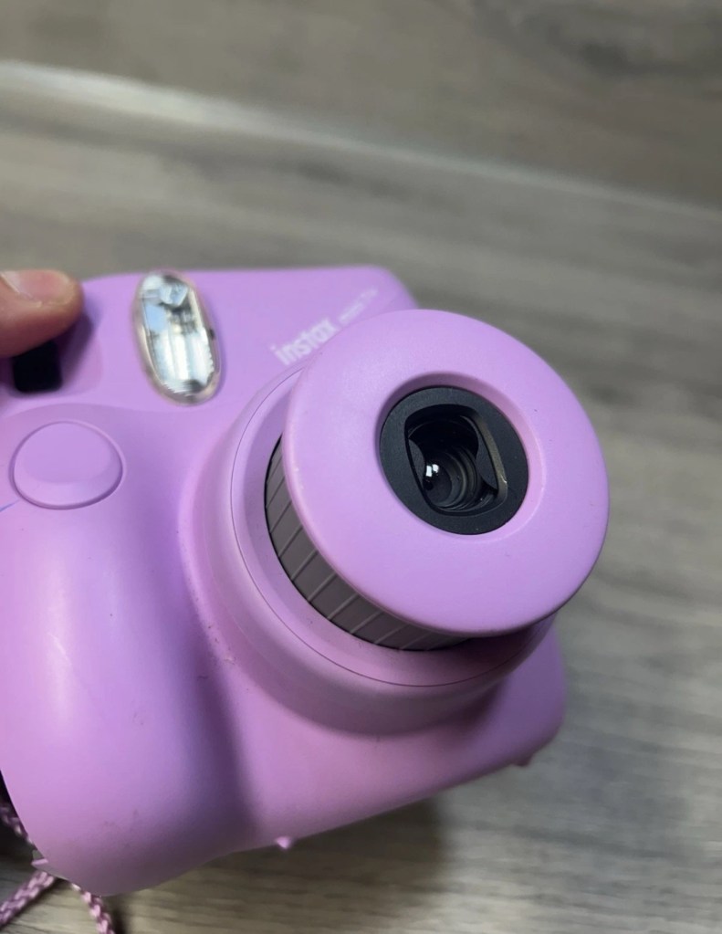
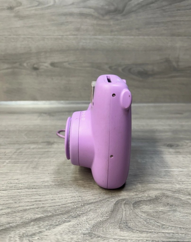
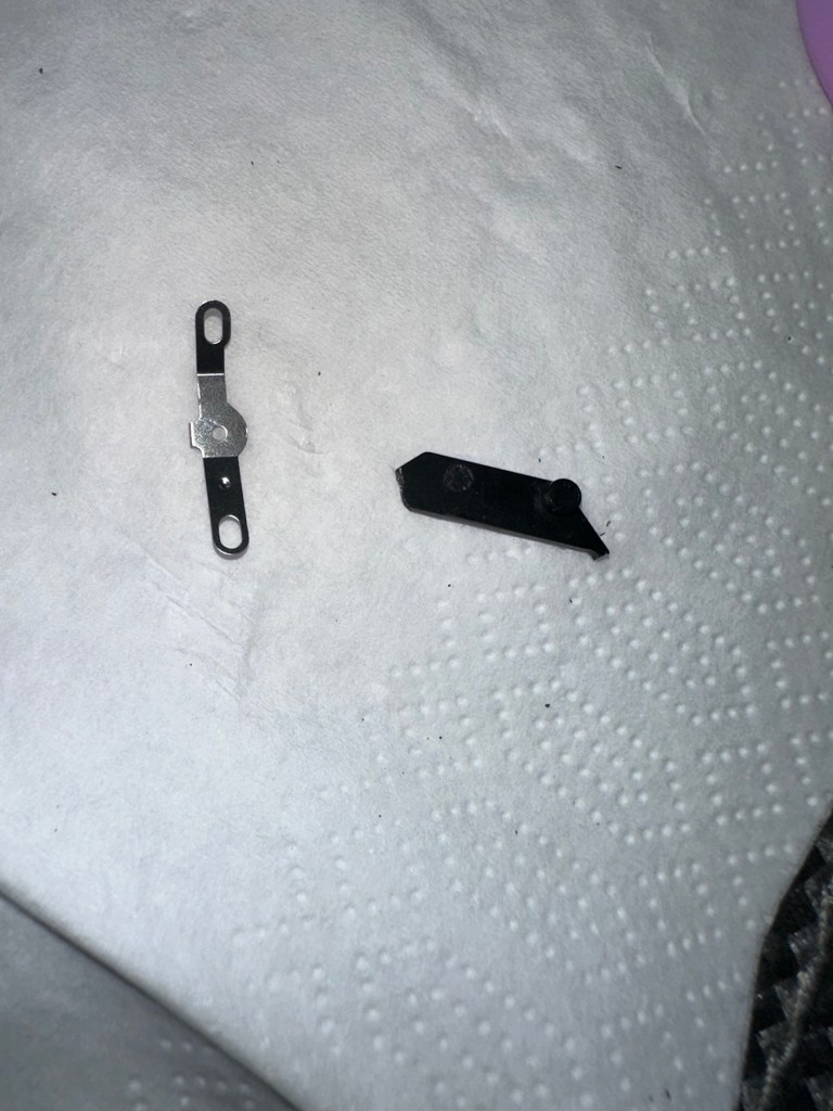
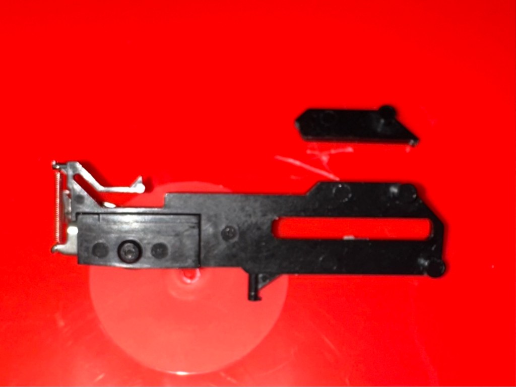
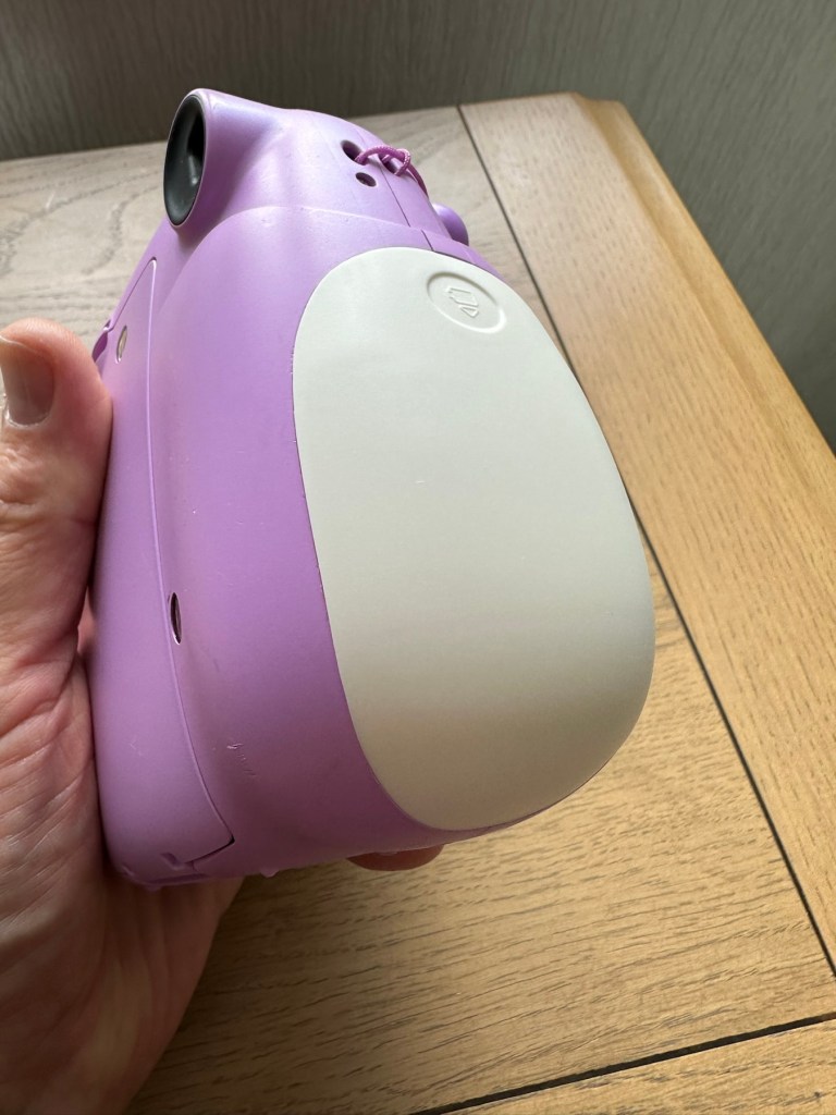
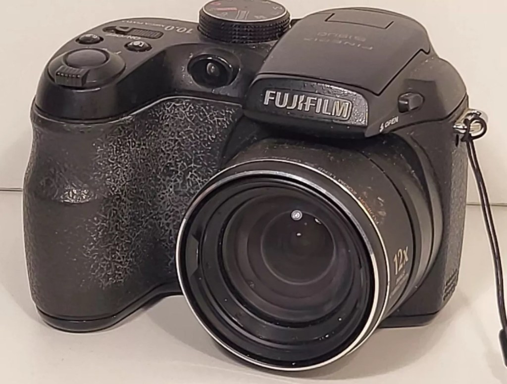
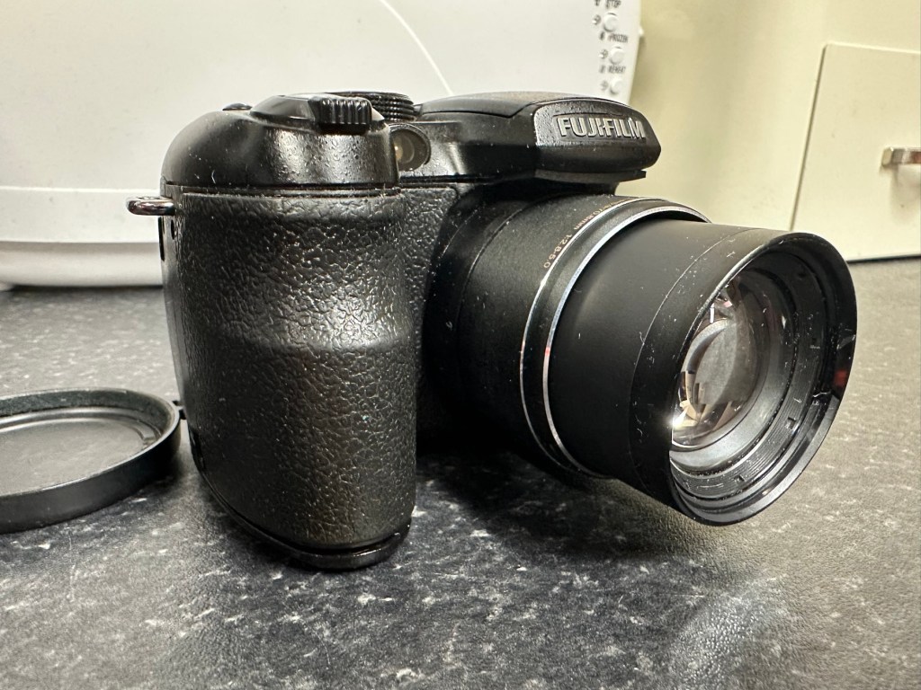
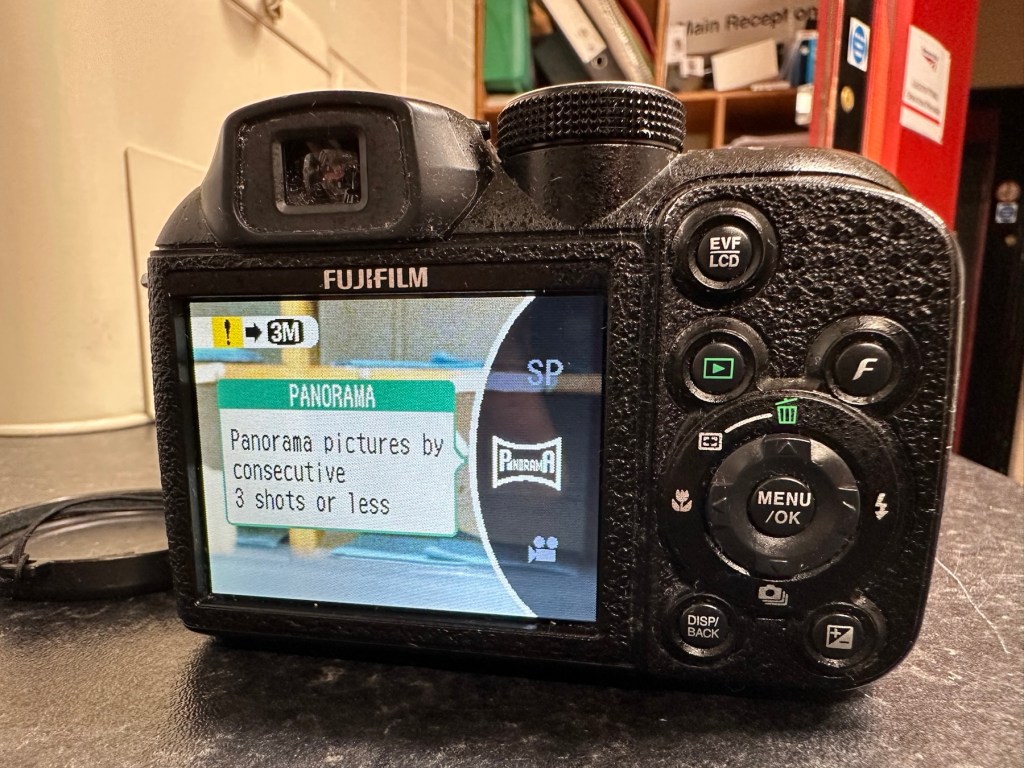
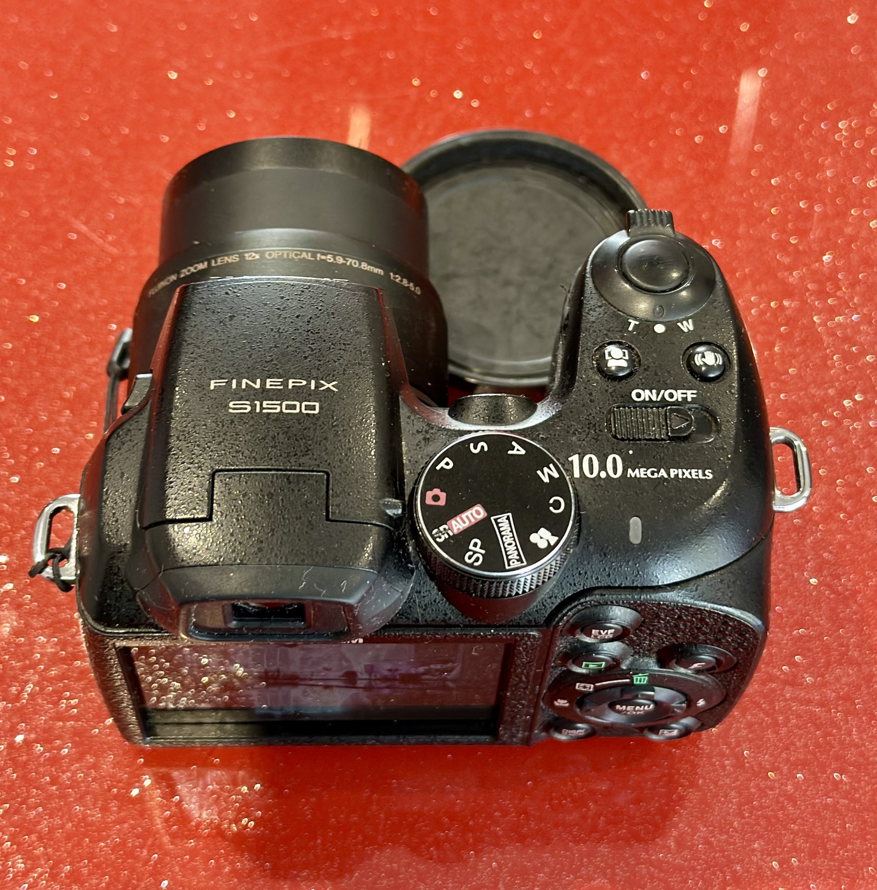
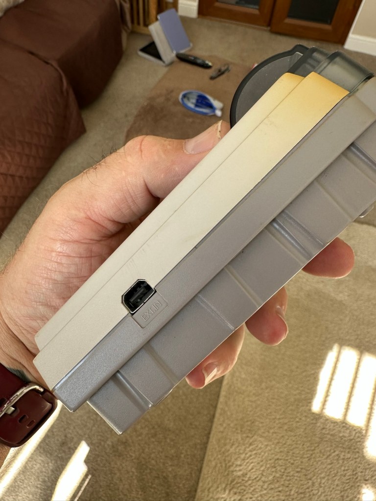
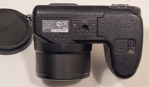
It’s arrived and to be totally honest, it’s in a right poor condition cosmetically. Very poorly packaged, I suspect the seller couldn’t wait to get it out of the door. Here are two of the better looking pictures.
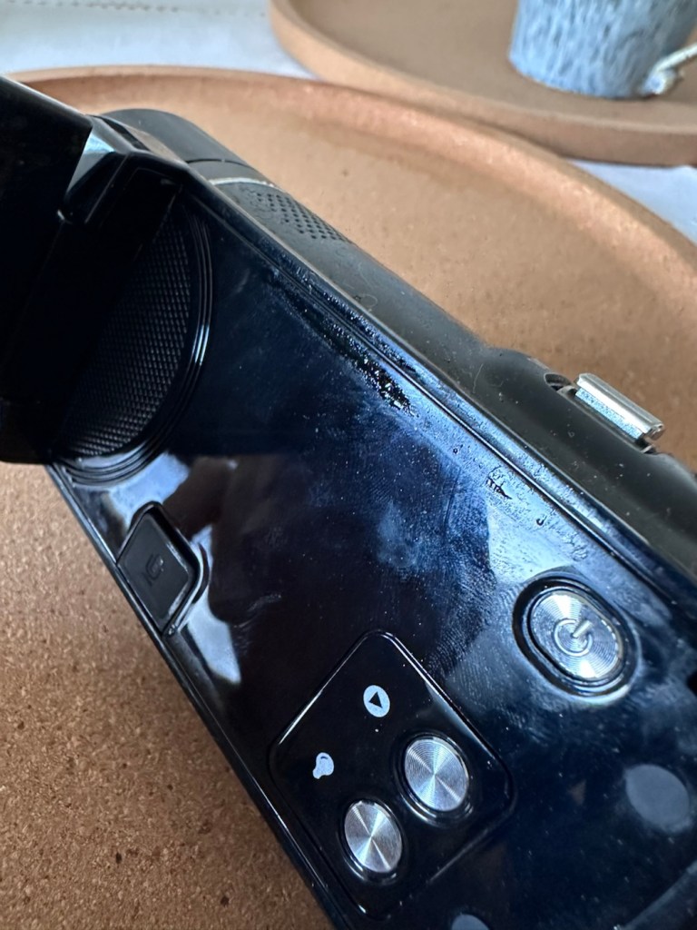
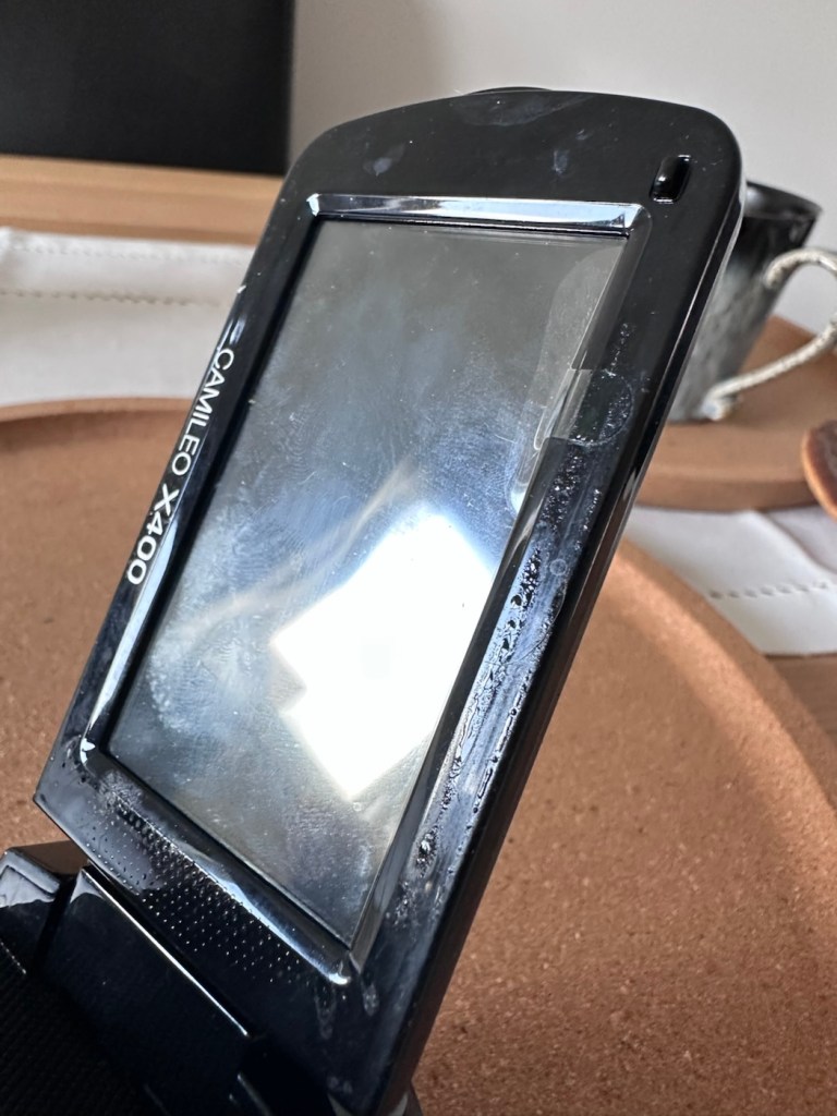
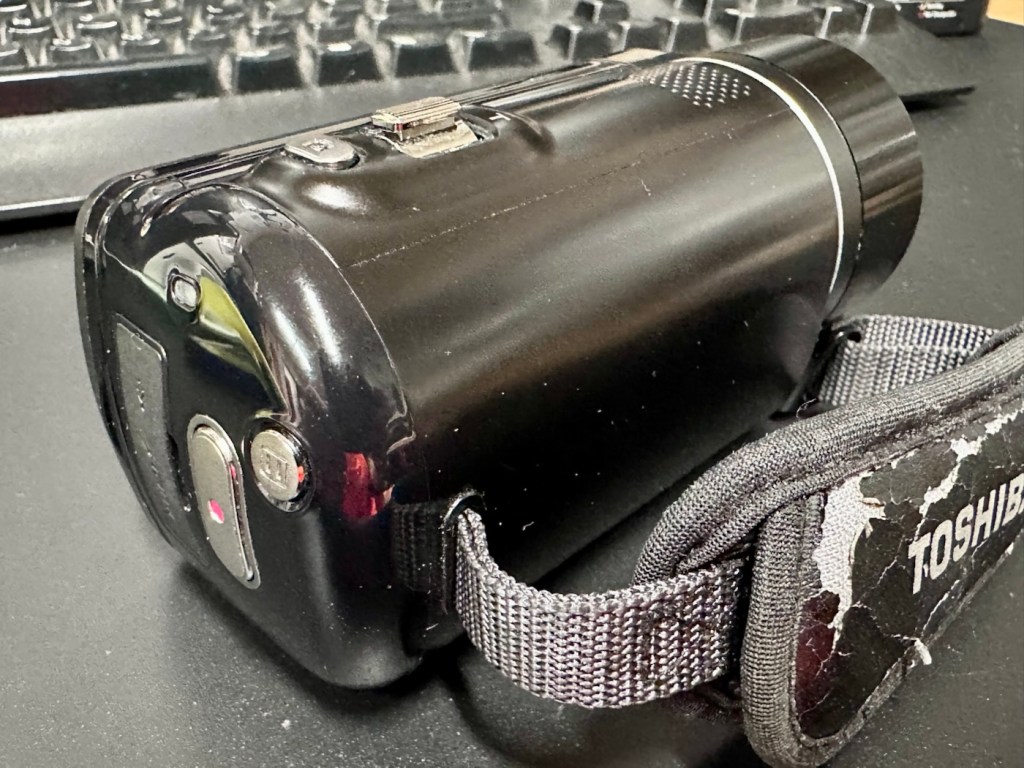
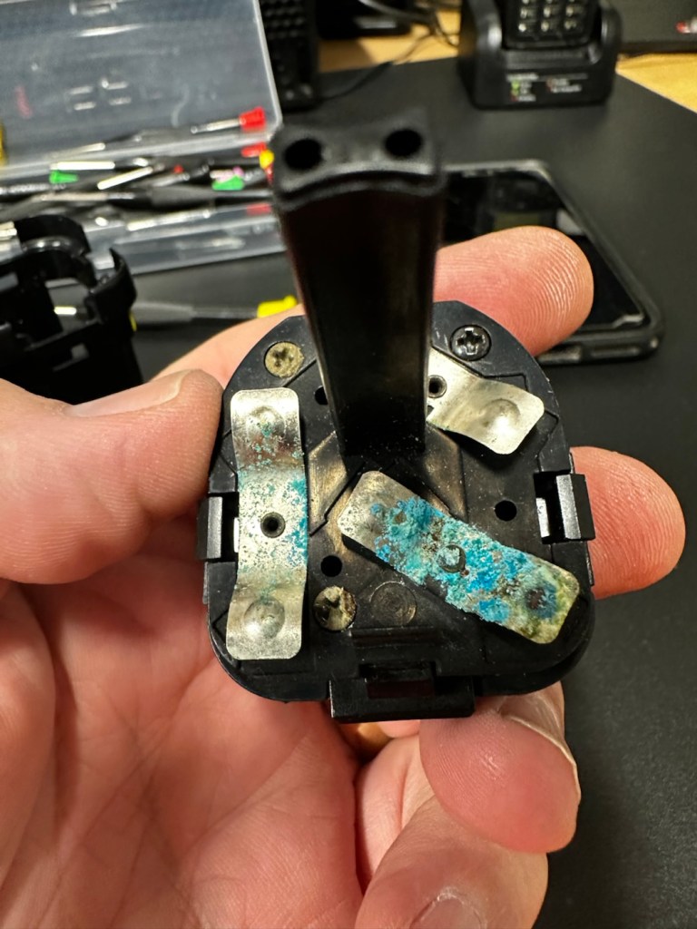
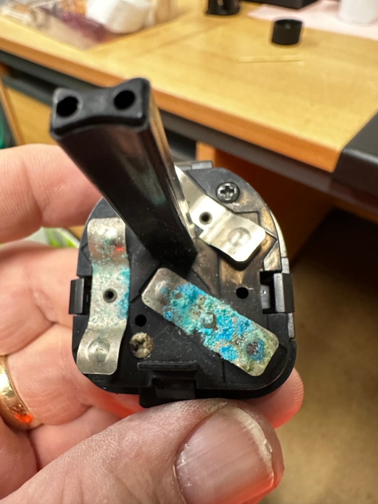
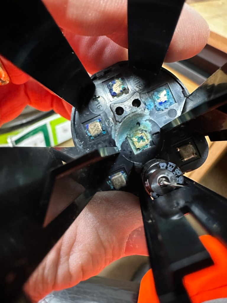
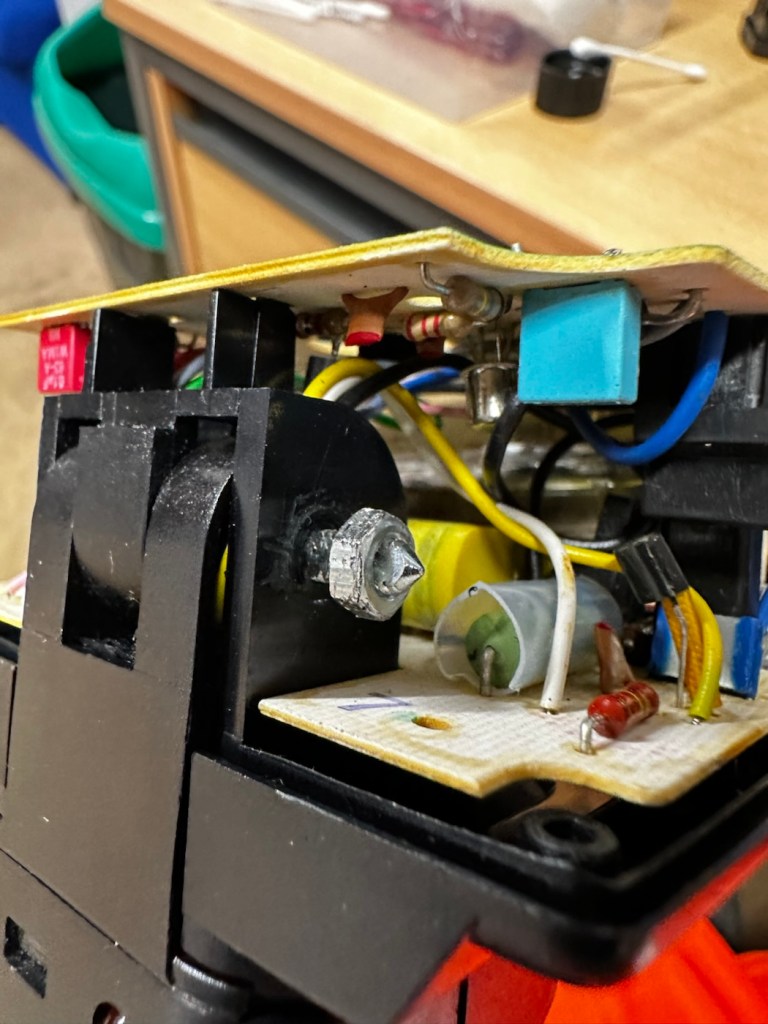
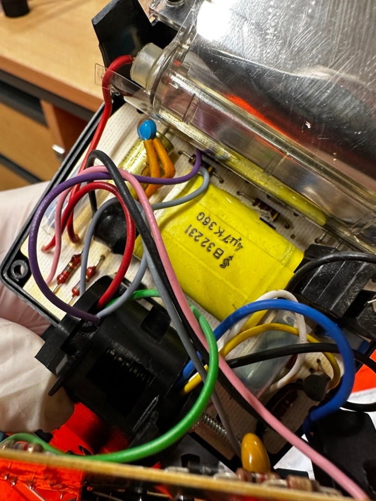
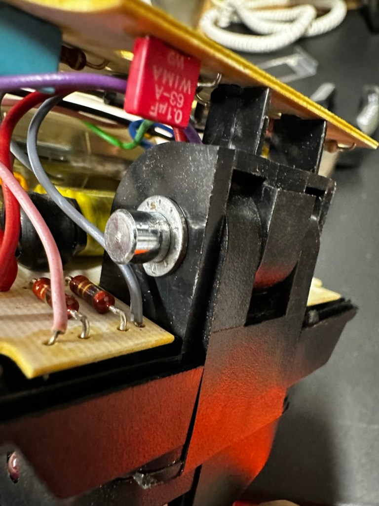
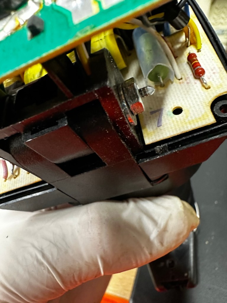
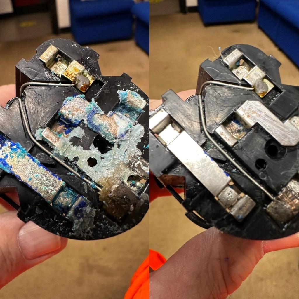
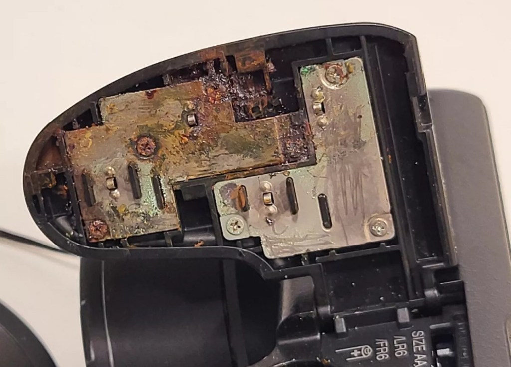
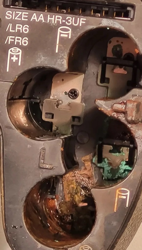
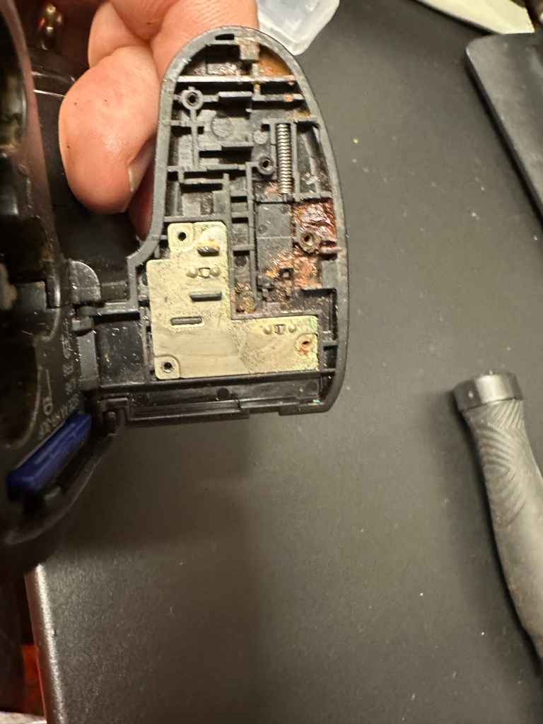
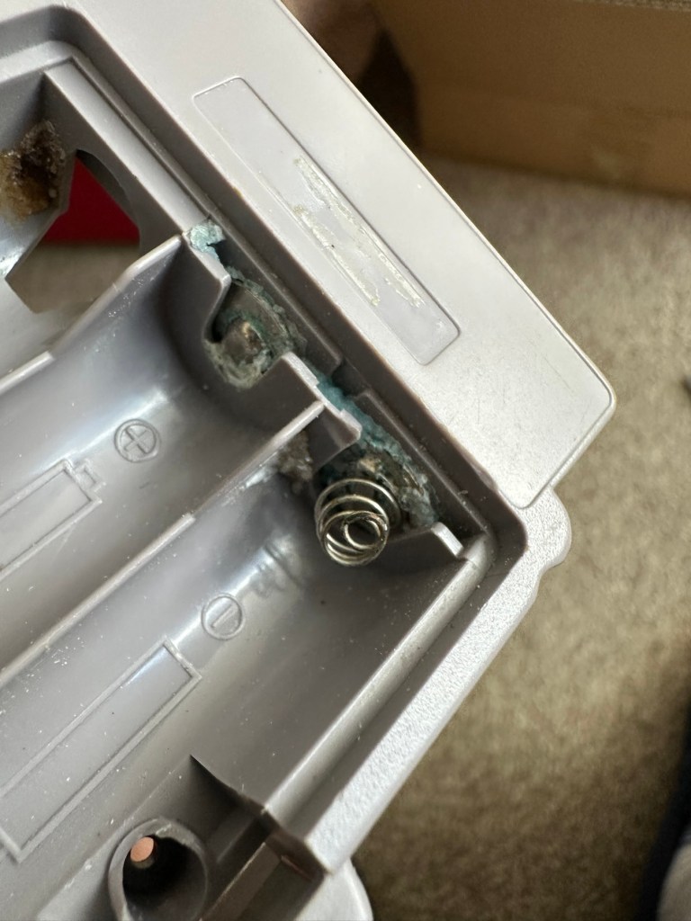
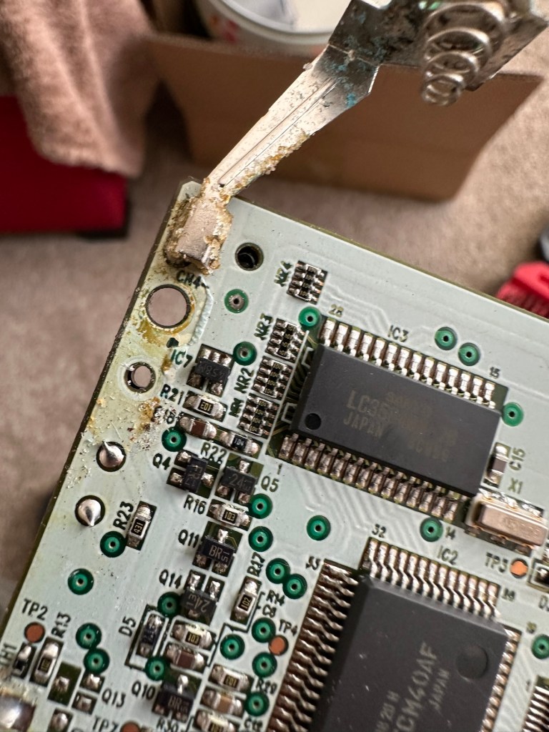
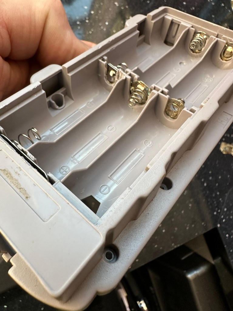
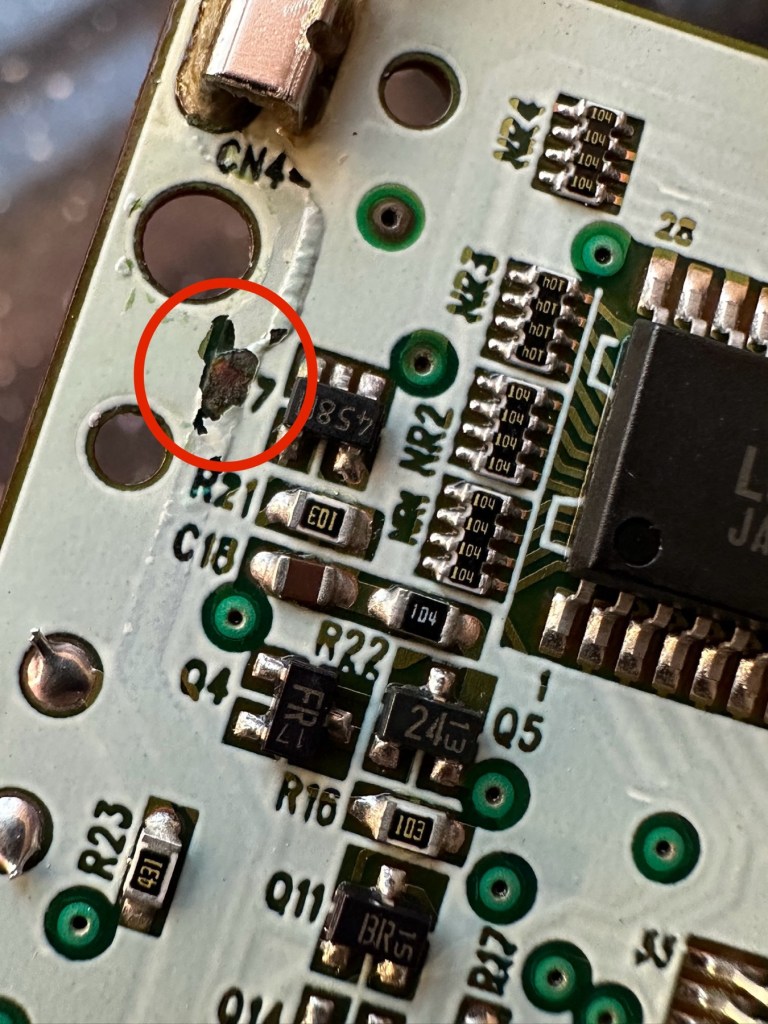
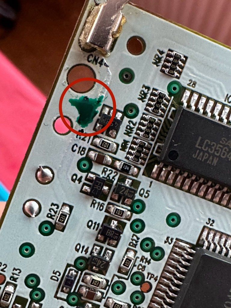
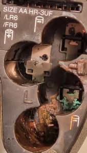
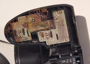
As soon as you pick the unit up, the stickiness the seller wrote about becomes obvious. It’s as if this camera has been immersed in a vat of molasses, it’s super sticky and if you review the close up pictures below you will see this unit has obviously been involved in some sticky situation, in places it is still wet, with liquid clearly visible, however that liquid is in a super sticky state of suspension.
…The bad, and the very ugly
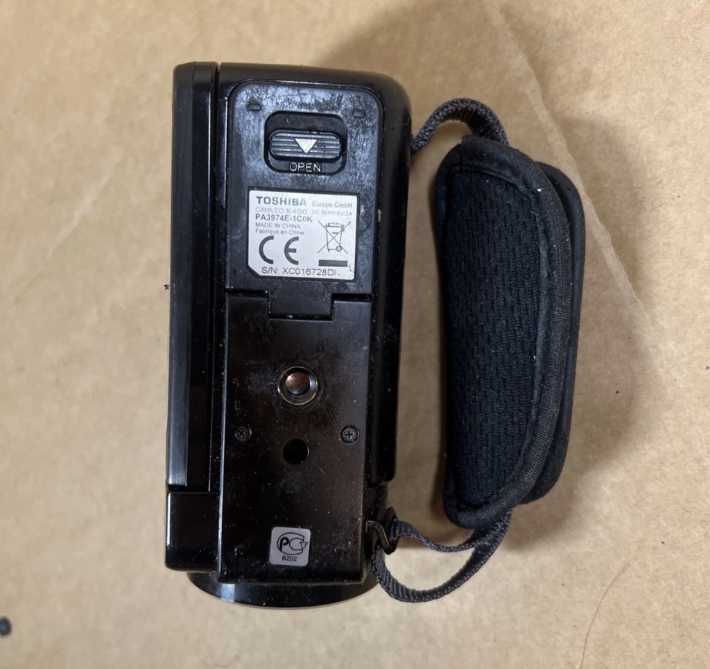
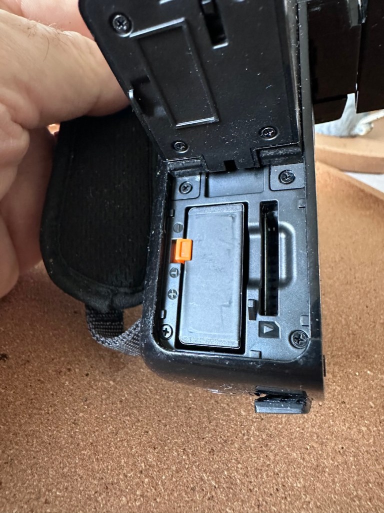
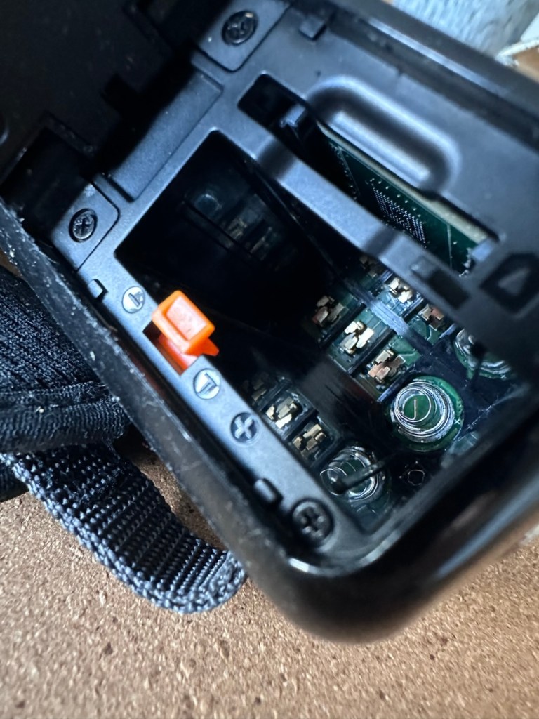
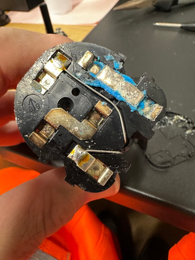
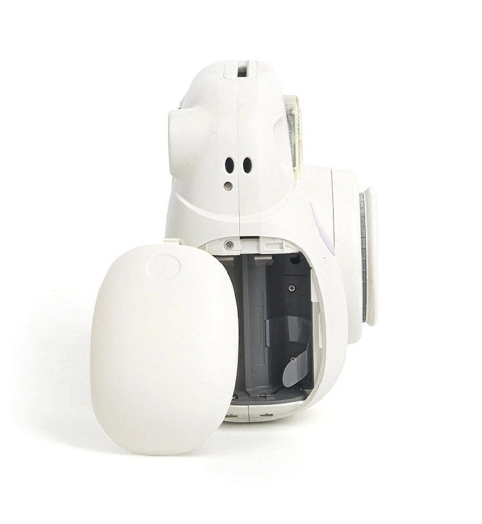
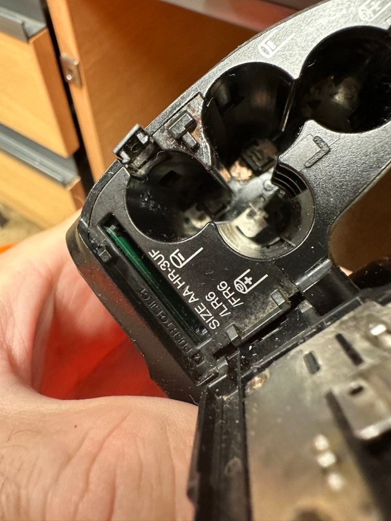
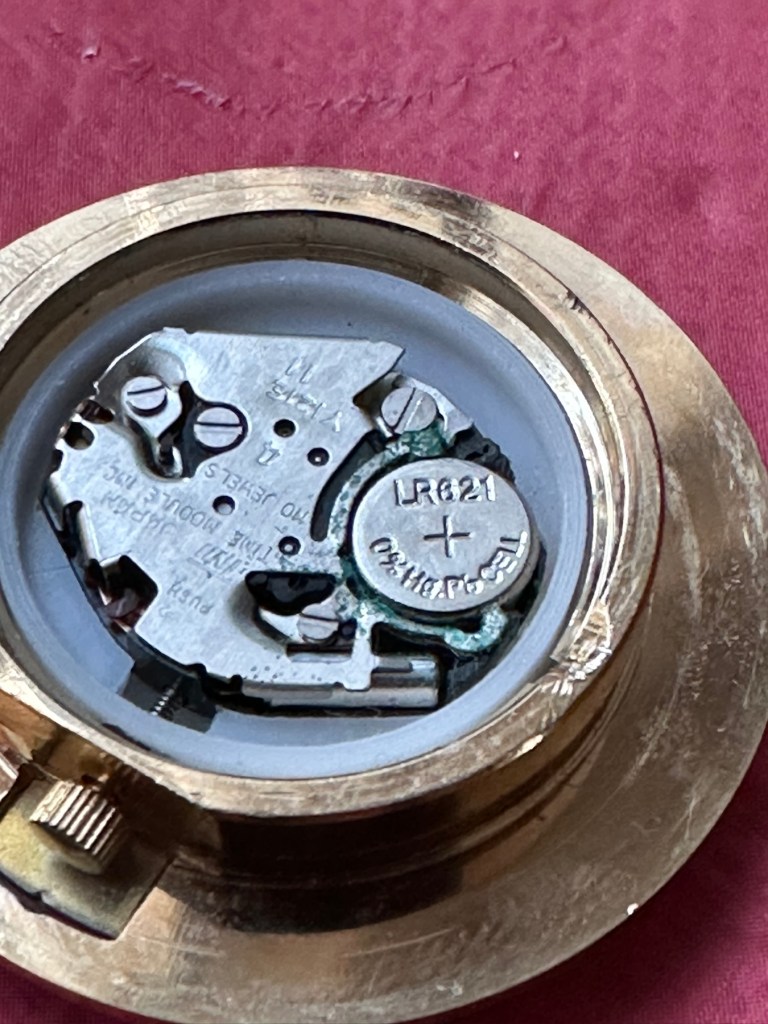
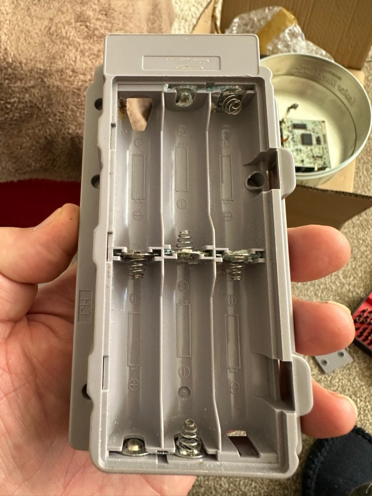
The battery is in place, I suspect it is dead but it will need to be tested, thankfully the battery contacts are clean and luckily it appears that no liquid has managed to reach these areas.
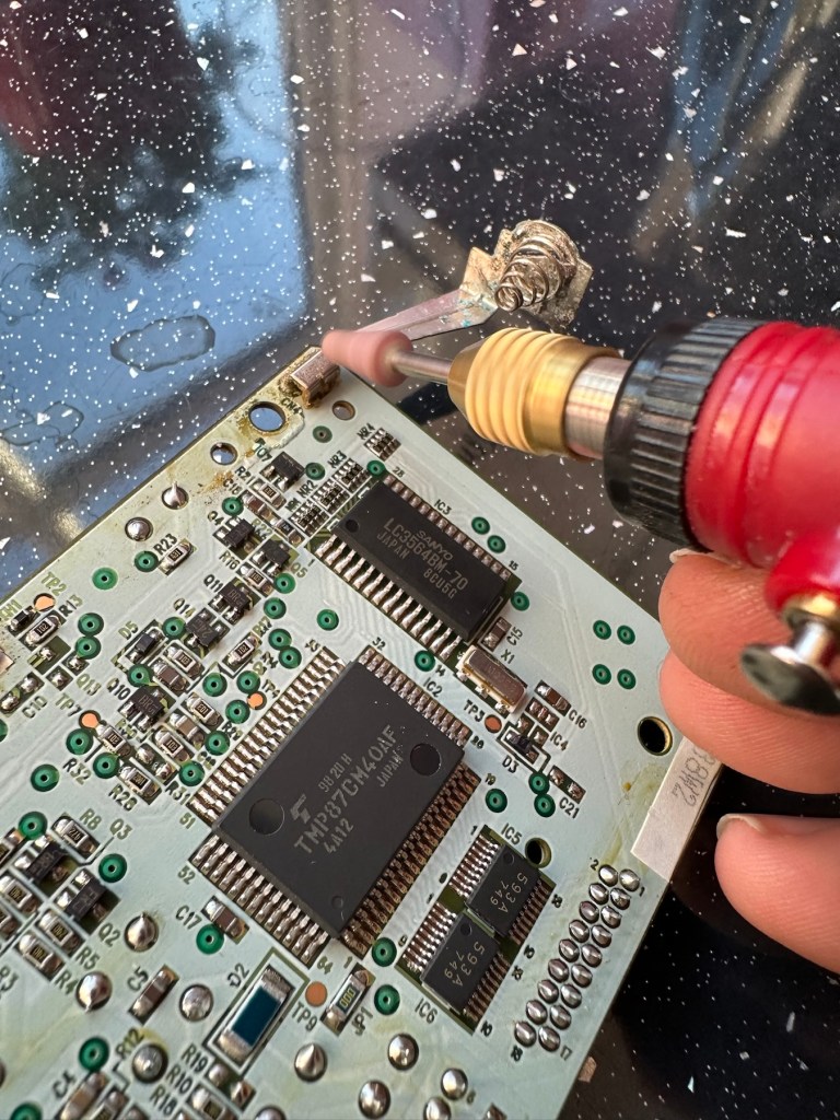
Before I even start to look at anything with this camcorder, a very thorough clean is the order of the day. It’s not going anywhere, and I’m not doing anything with it, until it is in a more presentable and workable condition.
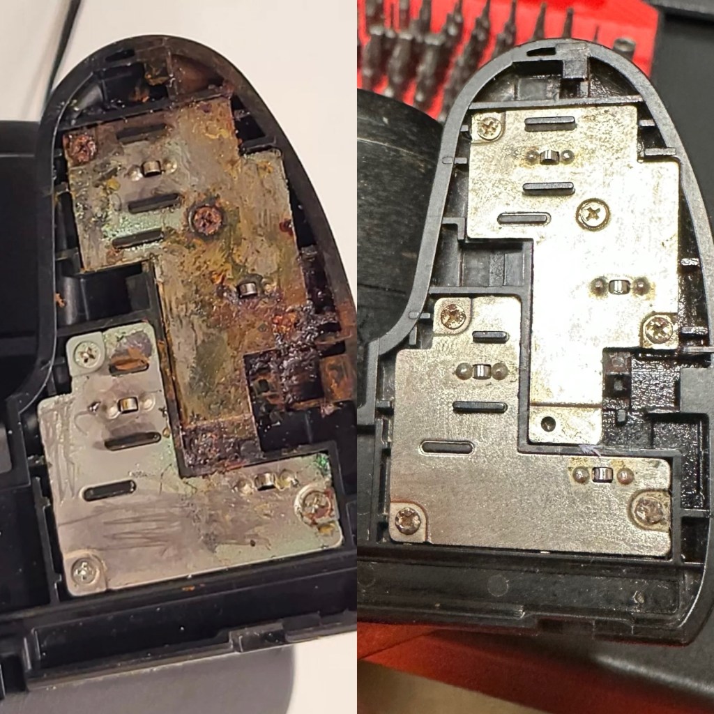
I like to use a disinfectant spray when taking on a job like this, in fact I use it on most of my old cameras especially those that have an old musty aroma. The disinfectant has cleaned this unit up very well removing all of the old stickiness and residue. I finish off with some polish and a cloth and the beast has now been cleaned and is now in a much better condition to start looking at where the problem may lie.
Well, to be totally honest the unit is kind of dead. There is a minimal voltage in the battery and when I find a suitable charging cable and install it, there is not a great deal else occurring. There are some lights, but they are not doing what they should be doing, I’m expecting lights to flash whilst charging, and a solid light when charged. However this isn’t happening, so let’s move on to what we are going to do to try and resolve this issue.
Repair:
For the moment I’m going to focus on the battery. We need power, so we do really have to start here, we can’t diagnose or do anything without some power. It’s a 3.7v Li-ion cell, and the camera can charge via a 5v USB supply. I’ve managed to locate a suitable charging cable from that drawer of collected cables that “may come in useful one day”, that we all seem to have stashed in our homes. When the cable is plugged in you should get some intro music from the camera, and I do. This should then be followed by a flashing light that should remain lit until the battery has sufficiently charged. However I manage to get about two flashes from an amber light and then that’s it… nothing else. So far it’s positive that we have seen some life, however we need to see if we can encourage this battery to take a little more charge.
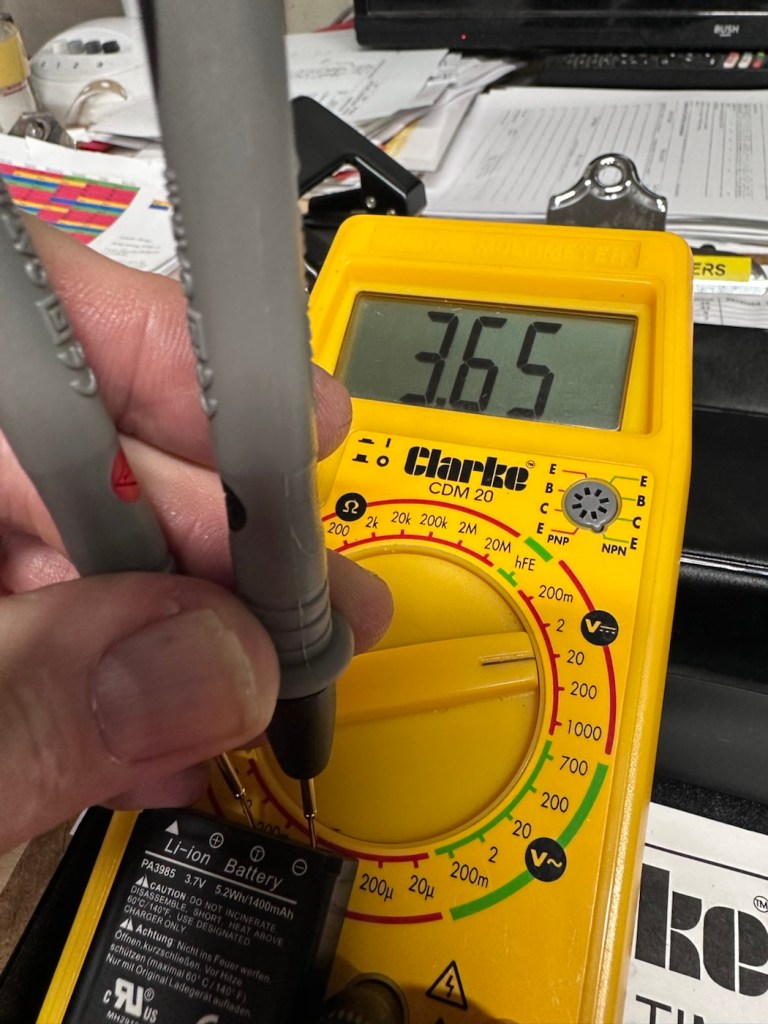
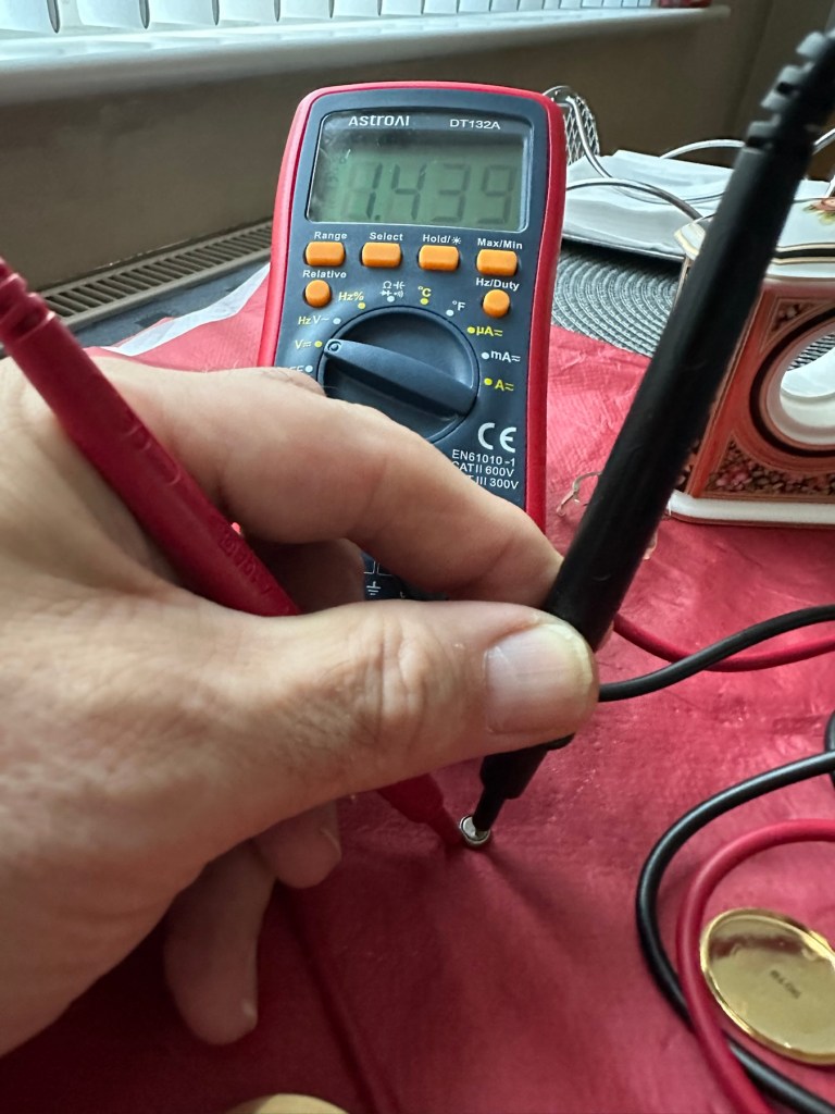
These batteries though rated at 3.7v usually charge up to 4.2v at full capacity. I’ve just measured this one with a multimeter and it currently sits at 2.64v. In the world of batteries this is severely depleted and to be totally honest looks as if this battery is dead.
A fully charged 3.7V nominal battery typically reads 4.2V, with 3.7V-3.8V being the average voltage during discharge. A 3.7V Li-ion battery is considered “dead” or fully discharged when its voltage drops to 3.0V to 3.2V.
While many protection circuits cut off at 2.5V to 2.75V to prevent damage, discharging below 3.OV frequently will significantly reduce the battery’s lifespan.
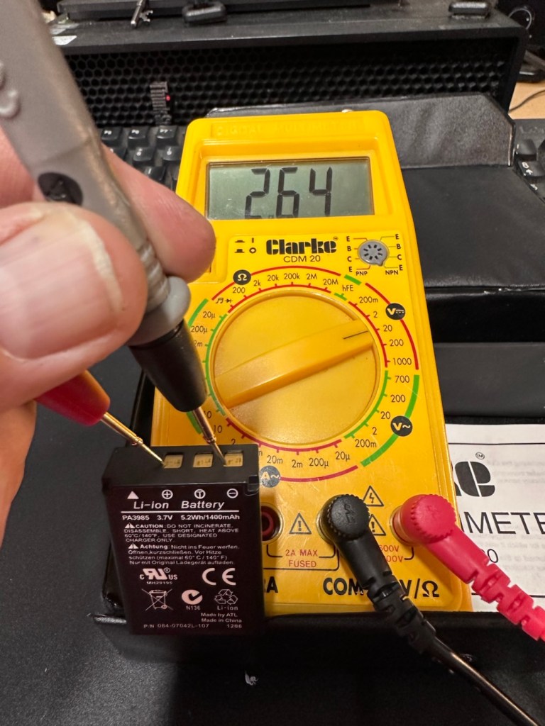
And it looks as if this may have occurred here. It’s looking as if the battery is a dead one.
However, I’m going to see if I can rejuvenate this battery by putting a trickle charge through it, just charging it in the camera from a USB 5v power supply. I will monitor regularly for changes in temperature or other issues. I don’t have a spare around at the moment so if I want to do some basic checks on the unit I’ll just have to give it a try.

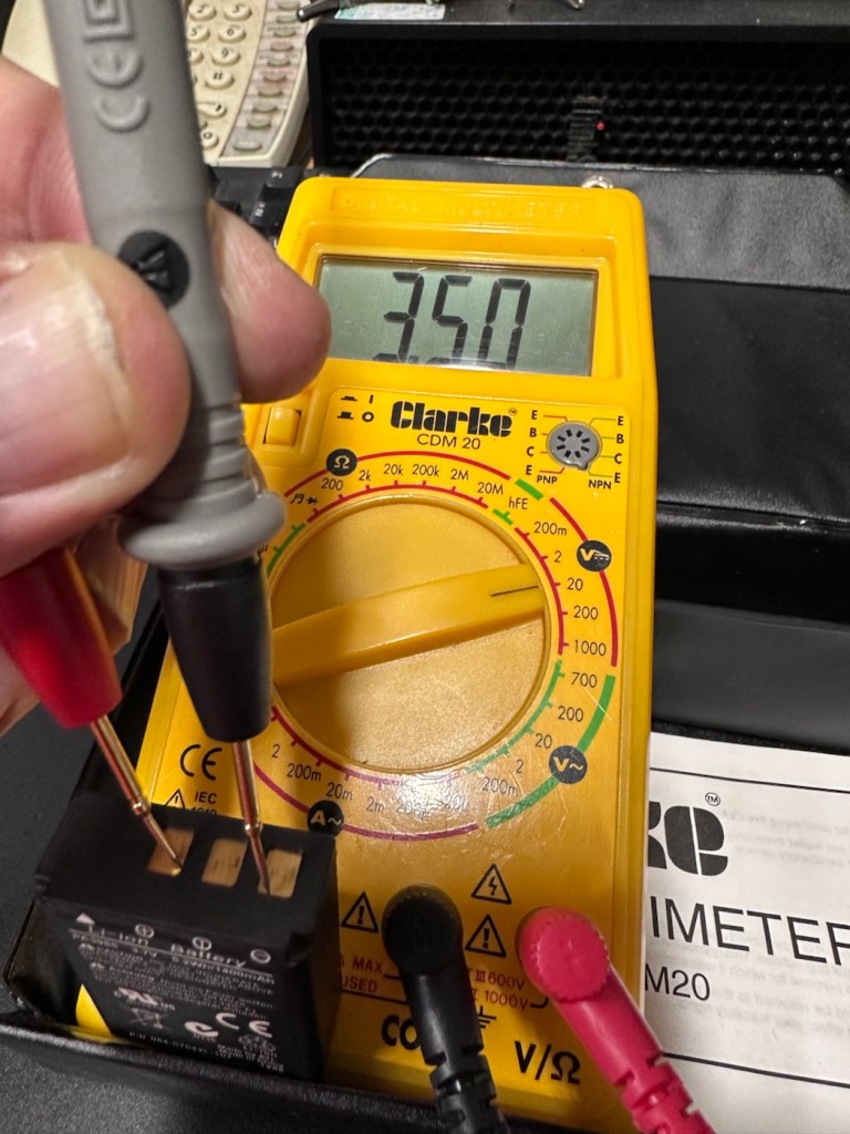
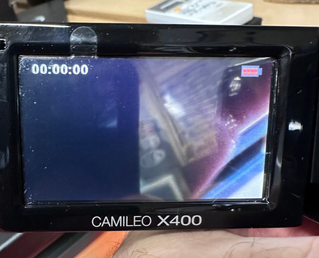
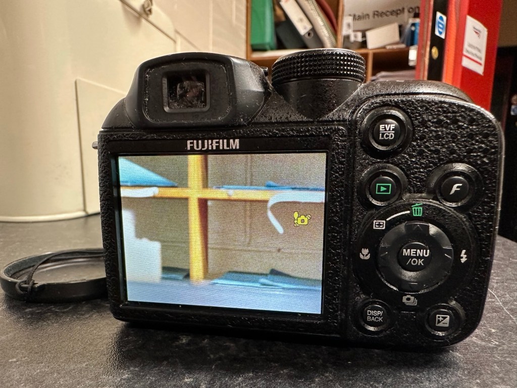
So after 3 hrs we’ve only been able to get about another 1v of energy into this battery, and as you can see we are only just into the battery depletion range. We have sufficient power to start the unit up and see a welcome screen, the zoom works. It’s clearly visible that there is a low battery indication on the screen and then it all shuts down again.

There is just not enough life in this battery to sustain a 30 second video, the battery is just so worn down that I believe it is beyond resurrection. I may have to purchase a new battery to finish off this section of the post. It’s good though that we have tried, rather than just give up, and this has also allowed us to review what we have found out about the process, and the good news is that at this point it, is looking as if it is purely an issue with this battery.
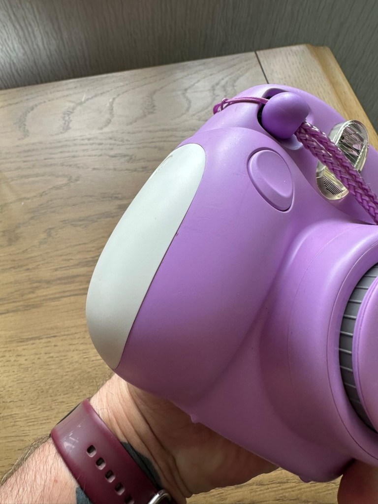
The camera has cleaned up lovely and really looks like a nice piece of kit. For the moment I will put this post on pause whilst I await a replacement battery.
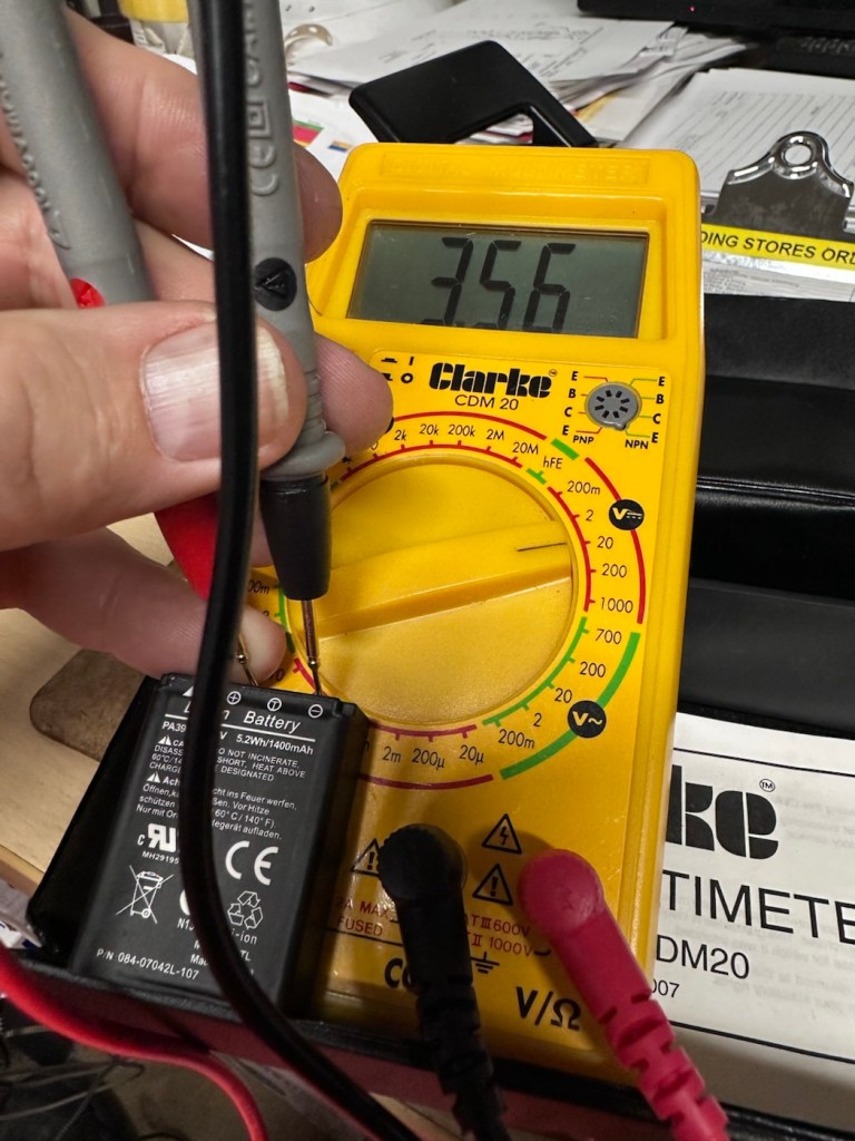
But…. Me being me, and not wanting to spend too much money at this point, I have persisted with leaving this battery on trickle charge. It has been consistently monitored to keep an eye on it, and I must admit neither the battery itself or the charger has been hot or even warm throughout this entire process, that is good.
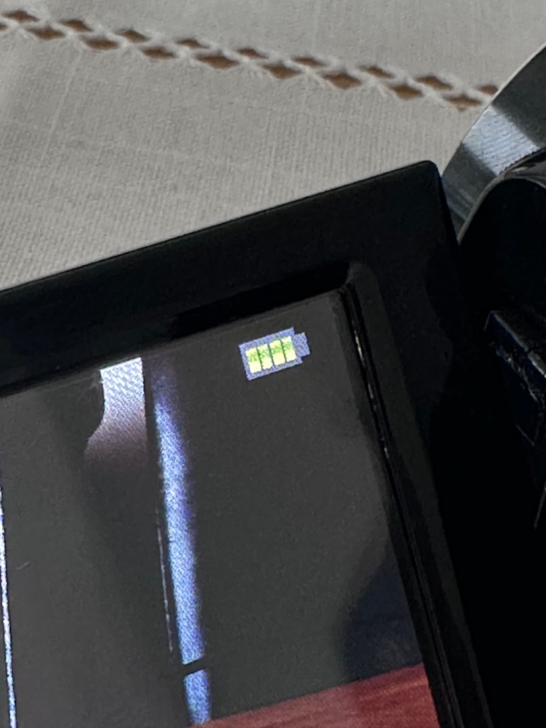
Seeing that about 4 hrs ago the battery indicator on the screen was only showing two green bars, it is now showing four bars and that indicates it is now fully charged. Let’s get the multimeter back on, and check to see what the current battery charge is and see if that gives us an indicator to show if the nominal charge has now been achieved, I’m quite excited at this – I’m easily pleased and excitable in equal proportions – I have a feeling that with patience and persistence we may have well just cracked the issue. So what is the current voltage of this battery? Well, here it is….
4.14v
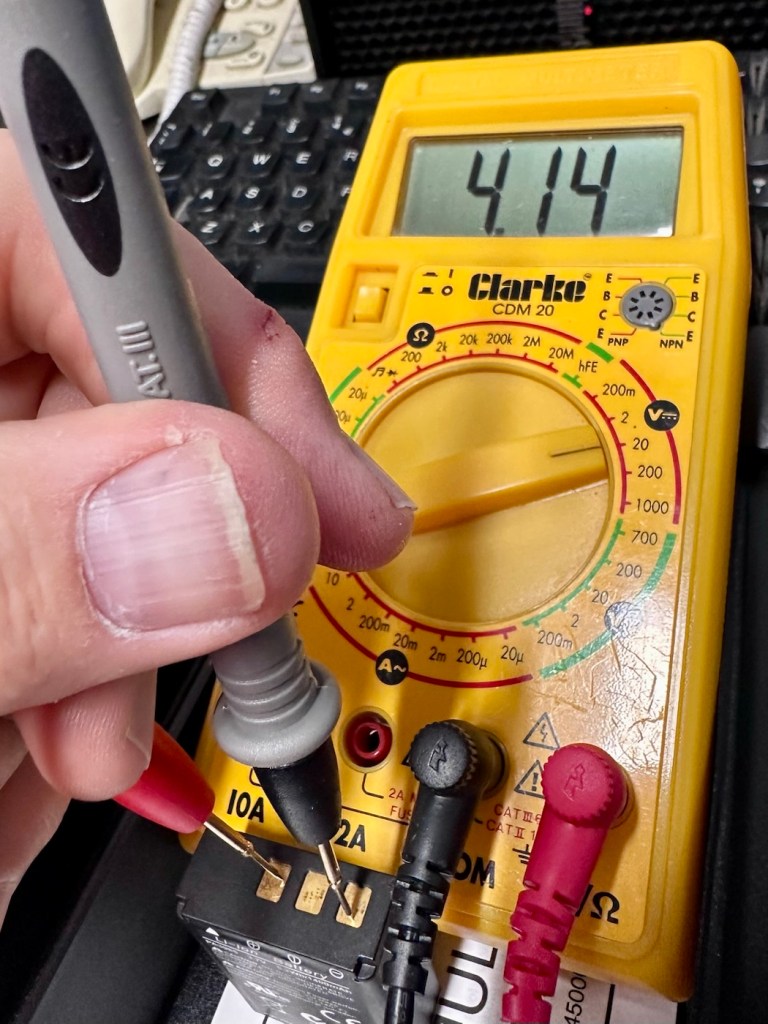
Well, I’m very pleased with that, not only has it charged fully it appears to have reached pretty much full charge beyond the nominal charge. I’ve probably saved this battery from the trash heap, but I guess it will be more of a backup battery for me as I will probably purchase a new one, for my main battery, now though, there is no rush as it looks as if this one has been rejuvenated.
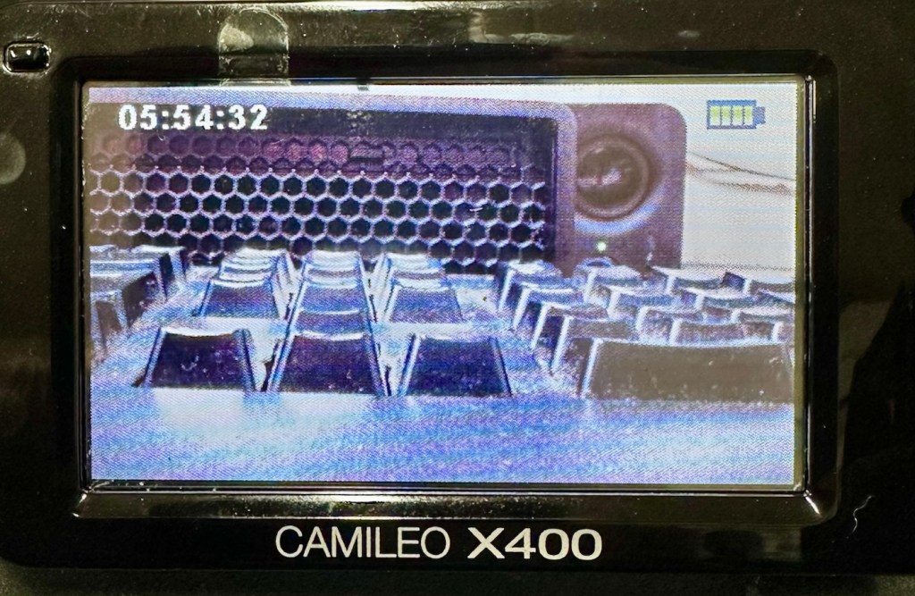
I’ve put a 32Gb SD card in and the screen is indicating 5 hours and 54 minutes of recording time, however on a full battery and using the minimum of activity (Not using Zoom and other effects) you can normally squeeze two hours of recording from the battery. But I’m never going to be filming war and peace, and I’m probably never going to get that kind of usage from this battery. My best bet with this battery is to not let it deplete totally, and try to keep it in a charge cycle were it doesn’t dip below about 25% of its capacity if I can help it.
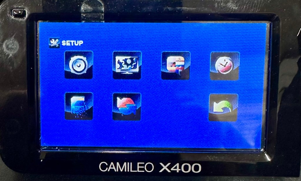
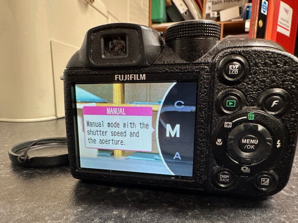
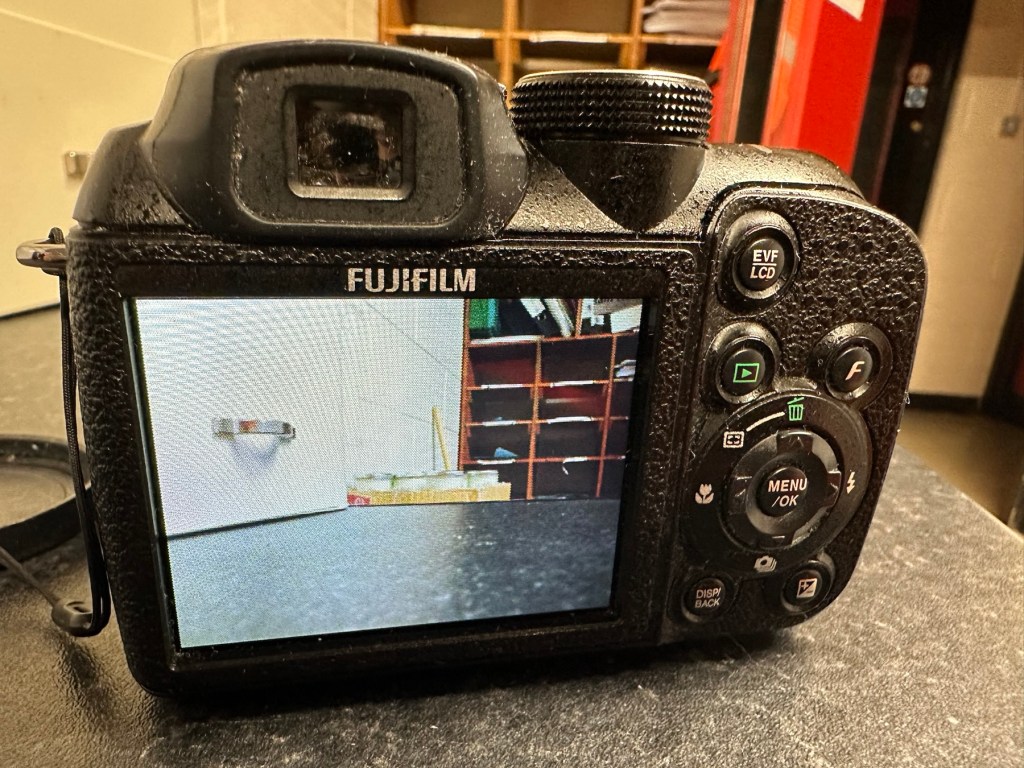
I’ve tested all settings and everything is just fine. The touch screen is responsive and all setting and special effects can be easily accessed. There is nothing else wrong with this camcorder.
At this point I am now happy that this camcorder is a fully working and very capable little unit, that should serve me well as I use it to make videos for my YouTube channel and WordPress site. Repair is complete and successful.
Result:
This little camera cost me £7.00GBP and it’s been a fantastic restoration as such as it has not cost me a penny more than what I have paid for it. All I have done is invest time, done a lot of reading up about the intricacies of Li-ion power supplies, and done an awful lot of cleaning as this unit was probably one of the filthiest pieces of kit I think I’ve ever worked on.
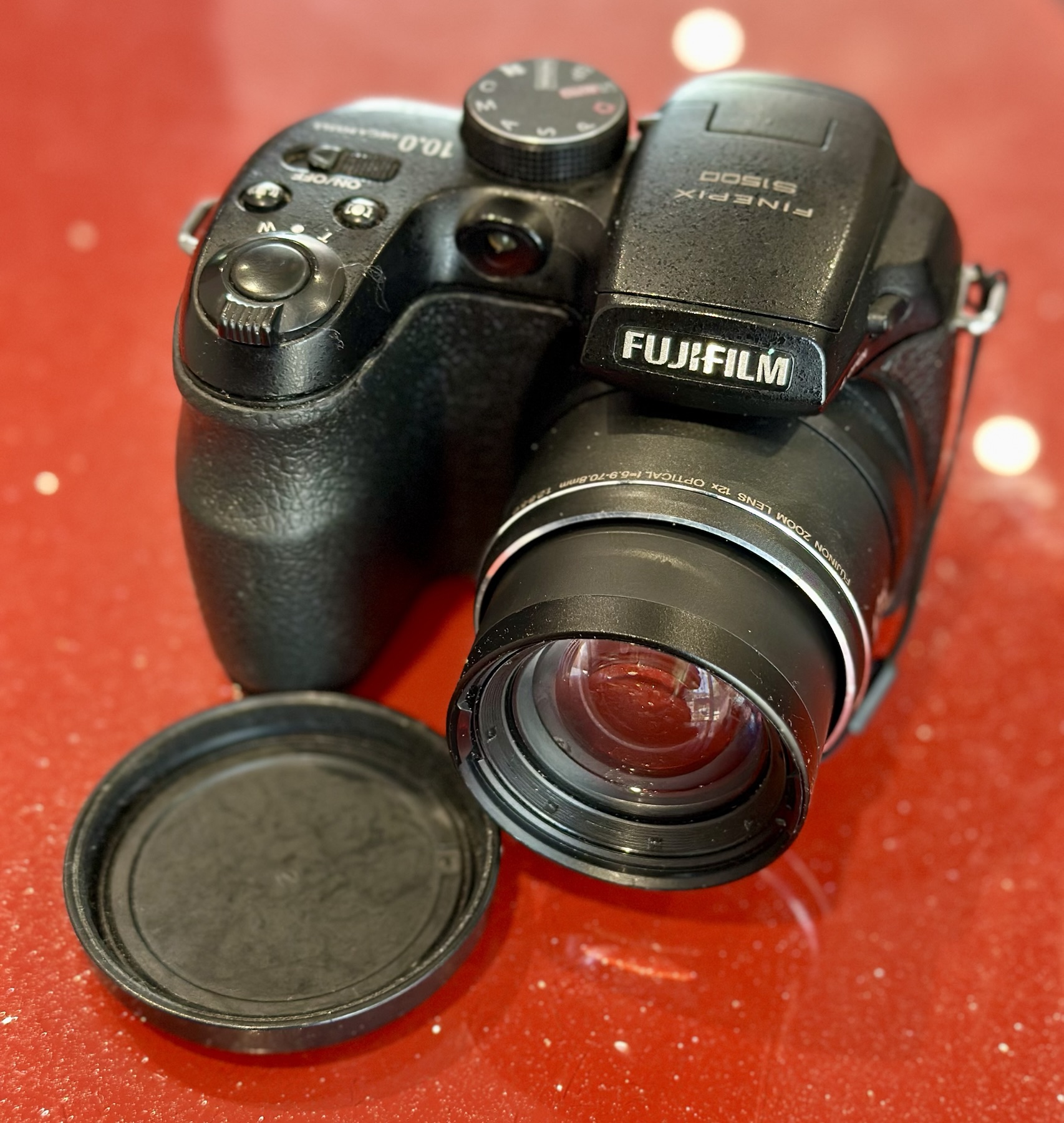
The camcorder is now a totally different looking camera from that which I received in such a sorry state just a few days back.
I’m going to use this camera myself for little items that I will be publishing here as well as on YouTube. It is so wonderful to see old unused and unloved items, repurposed and given a new lease of life.
Another one saved from landfill.
Thanks for passing by, as always it is very much appreciated.


You must be logged in to post a comment.