Canon Speedlite 199A flashgun

Can I bring a dead Canon 199a flashgun back to life? You betcha!

I love working with flashguns, but believe me they are highly dangerous and potentially deadly pieces of kit, once you get under the skin otherwise known as its protective casing. I inherited this one from a good friend of mine who is a professional photographer, the post regarding what he passed on to me can be found here: Cameras…i need more!

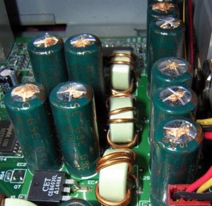
Now please do not go delving into the back of these things unless you know what you are doing. Yes they might only be powered by 6-9v of power from your batteries, however in the process of getting to the point where they unleash a lightning flash for your photographic opportunity, they have passed through a component called a flash capacitor, this component greatly amplifies the voltage from that measly 6-9v from your batteries up to what is now between 3-400v for the flash. Yes, you read right right, 400 VOLTS.

That can kill, and if it doesn’t, you have been very fortunate, but you will probably bear an entry and exit burn where you made contact with that very component. If it goes across both hands it’s probably going to go right through that pump in your chest that keeps you alive – your heart, and that can be fatal. You have been warned – take heed!

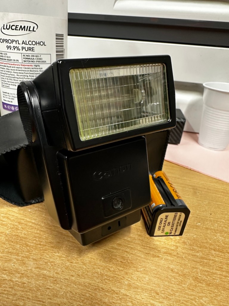
I must admit I’ve done something here I don’t usually do, and that is clean before searching for the problem. This unit had two or three old company stickers on it that I have now removed. I then gave it a quick clean and a buff and I must admit it has come up very well. I will give it another clean when i have finished, as well as a final polish with some cockpit cleaner.

Production of this flash unit commenced in 1978 for use with the Canon “A” range of cameras that were being produced around this time. It can also be used with some other camera ranges. Before we get into exactly what is wrong with this specific unit, let’s look at some information regarding the spec of this flashgun:

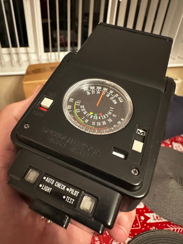
The Canon Speedlite 199A is a dedicated, thyristorized flash unit designed for operation with Canon “A” series cameras. The Speedlite 199A features a high Guide Number of 98 with ISO 100 film, three automatic flash ranges plus Manual and automatic bounce flash capability. The most powerful shoe-mount Speedlite in the Canon line, the 199A is recommended for use with the Canon A-1 or any “A” series camera with motor drive or Power Winder A due to its high power and very rapid recycling time.

Technical Specification: –

Type: High-powered shoe-mount flash; automatic, thyristor type
Guide Number: 98 (ISO 100, feet), 60 w/wide adaptor
Recycling Time: 10 seconds with Alkaline-Manganese batteries 6 seconds w/Ni-Cd batteries
Number of Flashes: 100- 1000 w/Alkaline-Manganese batteries 50-500 w/Ni-Cd batteries
Auto Flash Ranges: 3
Auto Apertures: (ISO 100) Red-f/2.8 Green-f/5.6 Yellow-f/11
Bounce:Yes
Flash Coverage: For 35 mm format, covers angle of view of 35 mm lens; covers 24 mm w/adaptor
Color Temperature: Daylight
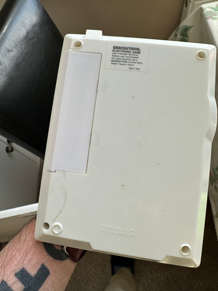
Power Source: 4 “AV size Alkaline or Ni-Cd batteries
Dimensions: 3-1/8 x 3-1/4 x 4-1/2 in.
Weight: 1 lb., 1-5/16 oz.

Mir.com

Asssesment:

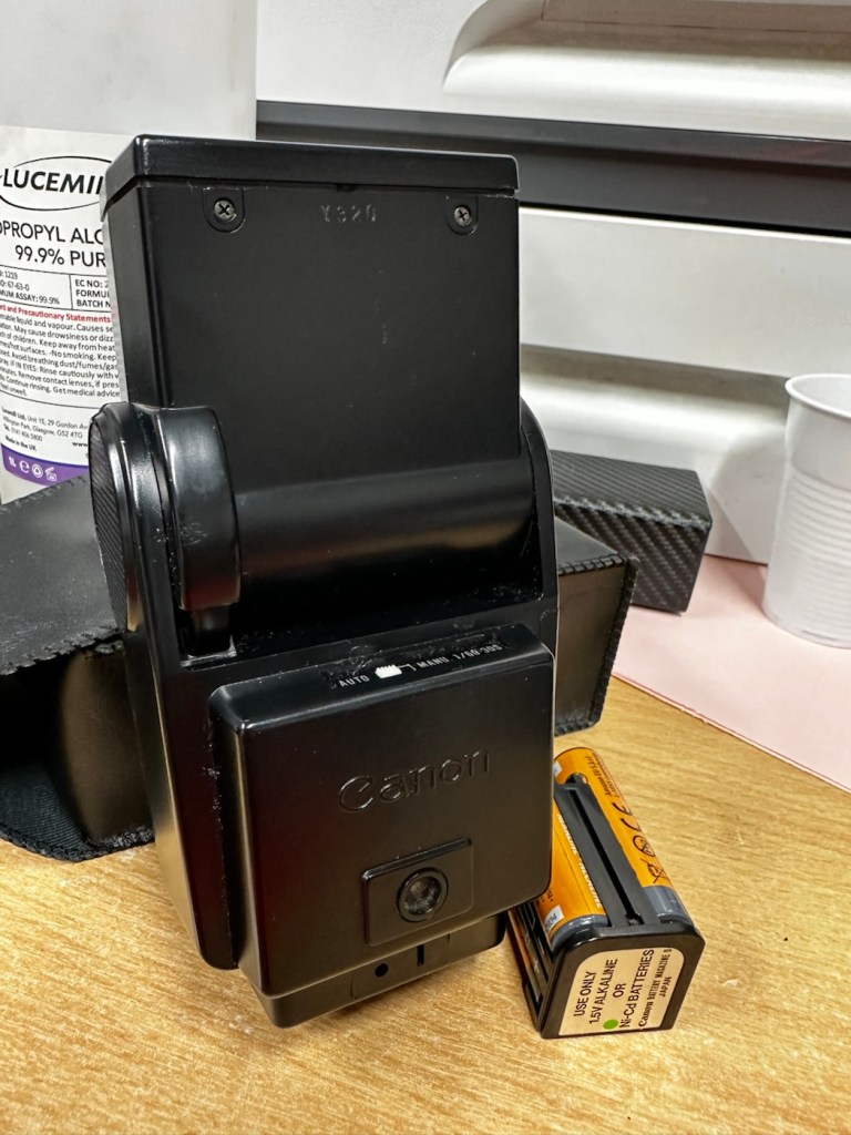
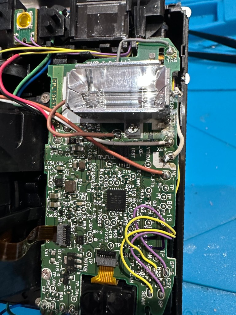
As you can see in the photos above, and as I stated at the beginning, I’ve gone arse about face on this one and cleaned it prior to diagnosing what the actual issue is. Please forgive me as I was in a cleaning mood at the time, and if I’m in that mood everything gets cleaned.

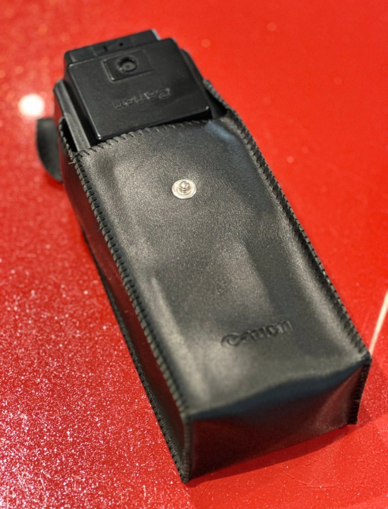
It runs off of four AA type batteries that fit in to a cassette that sits in the side of the unit. All contacts are clean and there is no sign of any battery leakage. You can see the cartridge in the photos above. The flash unit comes in a Canon branded leatherette pouch that is in absolutely perfect condition. Inside the pouch is a diffuser / wide angle lens that slides over the actual flash head. The whole unit looks fantastically clean and tidy, with no signs at all of any damage or wear.

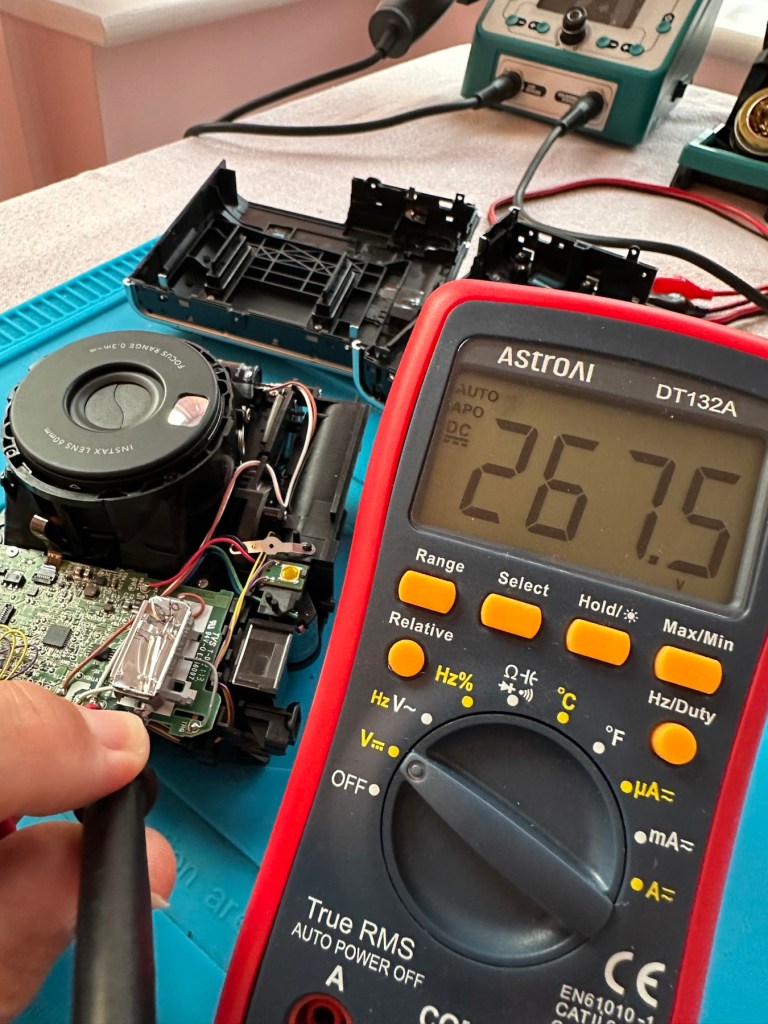
Put the batteries in though, and turn on the switch. And nothing. It’s dead. Kaput.

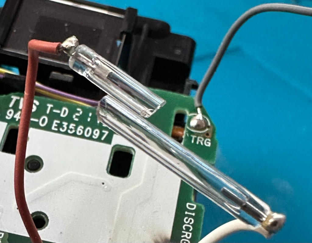
With these old flash units you were always used to hearing that family high pitched whistle when you turned it on. That was the system telling you that the capacitor inside was taking a charge and getting ready for business. Over time, the capacitor can loose its effectiveness, it semi retires if you like, and on occasions it retires fully, it dies a death. I very much suspect this is what could possibly have happened here, I just hope ours is in a deep sleep and can be woken up.

So as we move on to what we are going to do, the only issue here is that it’s simply not accepting a charge, and we will then discuss the two options on how we may now breathe life into this geriatric flash gun.

One thing that always annoys me when I search for possible ways of approaching the repair, is the attitude of people who have grown use to us all being consumer driven, the attitude stinks. These units can be purchased for very small amounts now and they loudly advise,”Just buy a cheap replacement and throw that one away!” This annoys me as you well know, because that’s not what this site is about, if I can repair something, no matter how inexpensive it is, I will. There is no need for this continuous throw away attitude. It’s a good way to learn just how things work.

Rant over, let’s move on….

Repair:

One of the easiest and least invasive, and therefore safest ways to start investigations, to look for a remedy, is to first get a nice fresh batch of alkaline batteries. With these in place within the unit, turn the flash power switch on and just leave it like that for anywhere between 2-8 hours. It has been known in the past, to act like a trickle charge as that flash capacitor has not been active for god knows how many years, it kind of revives it. It sometimes works, more often than not it doesn’t. But it’s worth giving it a try. So here goes. If this doesn’t work then our only other option is to get the unit opened up and to replace that beast of a flash capacitor.

I’m just coming off of a night shift and will shortly be heading off to bed, what better time to try this method out. So I’ll see you in a few hours 👋

And so the wait begins. Fresh batteries in place and turned on at 06:20….

I’ve arisen from my pit about five hours later, and what do you know….

Well, it’s only gone and bloody well worked hasn’t it?

And 5 hours later….it actually works

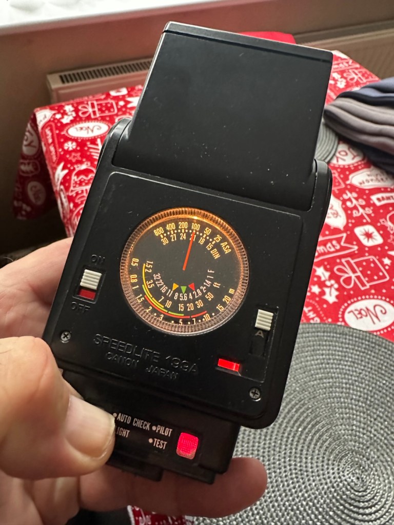
Sometimes it’s the simplest of procedures that can bring old equipment back to life, and when the fix is non invasive, going no where near those dangerous internal components, it can only be a good thing can’t it? And to think this was just placed in a box for disposal. Well it’s got a new lease of life now.

It really is working

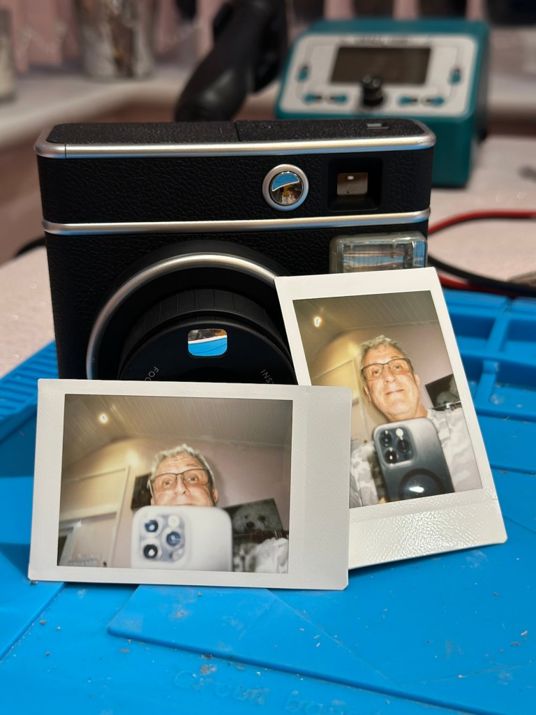
I’m really pleased with this so let’s move on to the final stages and get this little beauty polished and presented.

Result:

And yes it is a result, a result of patience and perseverance and thinking outside of the box as they say, in office inspired corporate management speak.

In a number of these “repairs” it’s best to exhaust all other options prior to getting the screwdrivers out, just like a surgeon explores all options prior to getting the knives out. I’m in no way comparing myself to a surgeon, you wouldn’t want me anywhere near you with a scalpel! I’m just using it as a pretty poor comparison, so I guess it’s best I shut up now and just get on with whatever I’m supposed to be doing.

So that’s another little repair put to bed, and another piece of electrical detritus pulled from the arms of the scrap man. I always feel a great sense of accomplishment when I mange to get these old bits of kit working again. It frightens me to think just how much salvageable tech equipment gets discarded when it could quite easily have its life extended with the minimal amount of intervention.

My plan is to add this flash to my Canon “A” series collection as that is what it was originally designed for. And I may well add a link here, when I get to use it whilst testing any new “A” series cameras that just happen to come my way, as they invariably do, that require my attention.

As always, thanks for passing by. It’s always most appreciated.

Fujifilm Instax Mini 40 instant camera

What the listing stated:

Fujifilm Fuji instax mini 40 instant camera . Functional, but flash NOT working . 

LISTED REPAIR OR SPARES . NO RETURN . 

THE CAMERA IS TESTED AND WILL,POWER UP AND TAKE A SHOT AND EJECT A SLIDE CORRECTLY. Please watch uploaded video . 

HOWEVER THE CAMERAS FLASH IS NOT WORKING . This is the reason I have listed the cameras as repairs or spares. 

Hopefully someone knows about these cameras and knows whether the flash unit just needs replacing or if it is an electronic fault that needs sorting out can fix it . Otherwise the parts will be useful to someone who repairs these . 

No batteries or film is included . 

The camera body is in very good cosmetic condition. There are only light surface marks in terms of signs of use . . Please see images as they are part of the description. 

The red light to show the camera has powered up lites up when the button is pressed to extend the lens and turns the camera on . 

When you close the lens down it locks securely into place .

The frame counter is working . 

The film compartment is clean and the rear door shut correctly and securely.

Battery compartment is clean and the battery cover locked into place securely.

The camera is powered by to easily available AA batteries ( not included) .

EBay

Now that’s what I call a great descriptive sales pitch. And that’s because the guy is a professional seller of photographic equipment. I’ve seen the video he posted and all the above is true, it really is just a problem around the flash. Maybe it’s an easy fix? I suspect not but either way it will be an interesting project.

Here’s a little info on this camera:

Hitting the market in April 2021, the Fujifilm Instax Mini 40 takes the updates the Fujifilm Instax Mini 11 introduced but wraps them up in a cooler, more retro-styled instant camera body. Instant film fans will probably love it and with its improved design, there’s a chance that those who aren’t instantly drawn to this form of photography may just want to have a play around with the Fujifilm Instax Mini 40, too. It does cost more than the Fujifilm Instax Mini 11, though, so you’ll have to decide if the cooler design is worth an extra £20. 

+ Pros

  • It’s fun
  • Great party camera
  • Easy to use
  • Looks cool

– Cons

  • Film is expensive
  • Viewfinder could be better
  • Powered by AA-batteries

Ephotozine.com

I first of all went in with a cheeky bid of £15:00GBP that the seller originally turned down, so I then put in a high bid of £18:00 and as no one else was wanting it, it actually sold for £16:00, just £1:00 more than I’d originally offered. All in all the cost with the postage was £19:45GBP and I’m really pleased with this. Im surprised though that there are flash issues in a unit that is only just four years old. As you can see in the photo below recent sale prices have been strong and a great deal higher priced than what I have just paid. These are certainly popular little camera’s with the younger generation.

Recent sale prices have been strong

I guess we will just have to await its arrival to assess the flash issue. I’m very confident that I will be able to get this camera up and running again.

Assessment:

Out of all the Instax cameras I have dealt with lately, this has got to be one of the best ones I have had my hands on. This is a mid range instax camera that is more sober in colour aimed at those who enjoy their lomography or better quality instant photography. It certainly looks good, and to be honest I’d rather carry this one around rather than a bright pink one.

Looking nice and sober

As posted in the description above it is in near perfect condition and a quick Look at the flash head shows that the flash bar within the unit is broken.

Let’s get on with replacing this damaged flash unit.

Repair:

Let’s get it opened up.

Dismantling

People laugh at me when i tell them that playing around inside these units could kill you. I can understand the contempt aimed at me for such a statement, when I’m carrying a bright pink camera that hardly looks dangerous. Just look at the voltage still in the flash capacitor though once I have opened it. Savage.

Residual voltage of 267v still in the flash capacitor

270v would quite easily send you across the room, if you had a heart condition it would probably be game over. I’ve learned my lesson in the past so I ensure I use a capacitor bleed probe before I go anywhere near one of these flash capacitors. The capacitor on this camera is rated at 320v, not to be messed with. Beware. What’s more impressive is that all this energy is supplied from two 1.5v AA batteries. Clever stuff.

I have a donor flash bar in an old spare unit. I have carefully unsoldered its connections and gently removed the very thin glass tube from the donor unit and placed this in the one situated on the new camera.

Carefully, once inserted into the flash reflector, i have soldered it back onto the board. All looking good. However I need to test the flash so I temporarily put the case on, bung in two batteries and turn the camera on. Press the exposure button and the flash fires perfectly. Happy days. I now can confidently reassemble the camera back together, and I’m pleased that when this is done there are no screws left over. All small wins.

I have some film available so there is no better time than the present to give it a try.

Result:

Nice flash – working

I’ve loved doing this repair, this is a good quality, great condition, and now in perfect working order camera, brought back to life with many more years of use left in it.

But it could have been just chucked in the waste. I’m keeping this one for my collection as it’s a fantastic example acquired at a very good price. Thirty minutes of attention is all it took.

Another one kept from landfill.

Many thanks for passing by. Always appreciated.

Grandstand Invaders from space game

What the listing stated:

Can’t get to turn on unfortunately. No battery cover. Any questions please ask

EBay

I know, there is no battery cover, however I have already sourced a seller of one if needed. This item looks quite dirty so a good soak might be the order of the day to get started. I’ll wait for its arrival before I jump to order any other bits for it.

Now as I’ve said in the past these units fall into that crazy price category on the selling platforms as the “New Antiques” of today. For an item that was low cost, somewhere between £25-40GBP when it came on the market, they can certainly command a wide range of crazy prices, here is an example of price ranges from today:

The massive range in prices for these units

This one I purchased today only came up for sale about 3 hrs ago and I thought it would have been snapped up by now, it hadn’t so I didn’t hang around any longer and purchased it for a total of £16:38GBP including its delivery. I’m not going to get too smug yet, as for all I know I may have just purchased an empty shell. Let’s wait until it arrives.

Here’s a little history of this unit:

Grandstand “Invader from Space” is a tabletop LED game dating back 45 years to 1980. Four ‘AA’ batteries power the unit or, alternatively, the Grandstand 5.5V@300mA power adapter (or an equivalent power pack) sold separately. The game, licensed to Grandstand, is a copy of Epoch’s “Invader from Space”

The company initially behind the “Grandstand” label was Adam Imports Ltd., (from 1980 Adam Leisure Group Ltd. and by 1983 Adam Leisure Group PLC) founded in 1973 by Chris Rycroft and Les Kenyon of Harrogate, UK. The company initially started as a mail order company and was the single largest supplier of calculators in the UK by 1974. By August 1978, George Bassett had acquired a 75% holding in the capital of Adam Imports for £750,000 cash, plus 60p in the pound of profits before tax in excess of £500,000 for year to December 31, 1978. Adam Imports was re-acquired from George Bassett by Chris Rycroft in 1980. It chiefly imported electronic products from other manufacturers such as VTech, Epoch, Tomy & Entex, selling them in the UK re-branded under the Grandstand name.

Wikipedia and others

So that’s the history

There is a good link to a similar repair on YouTube from a guy I follow named Stez Stix Fix, it’s very much worth a look and he has a great if not sometimes crazy way of diagnosing and repairing items. A cool guy though.

The Grandstand invaders from space game

Anyway back to my own purchase.

Assessment:

I must admit the unit doesn’t look as dirty as in the original pictures. The battery cover is missing and there is a crack in the side and a deep scar at the bottom, this won’t be too much of an issue if I can weld it all back together. I will still give it a good soak to clean it all up though. I’ve put four batteries in place, and the unit is definitely dead. There are no loose wires, voltages are getting around the board according to the multimeter and nothing is getting hot. There appears to be no short circuits, and then I notice this, capacitor CO7, slight bulge on top and what looks like leakage from the bottom. We have a candidate as to why this unit is not working.

CO7 looking unhealthy to me, you can see the component to the left that looks like it’s covered in a fur ball. The result of the old capacitor “coughing”

I’ll whip this out and see what we have but I suspect this old capacitor has failed and is causing an issue, heres hoping I have a suitable replacement.

Repair:

This little beast is a 330uf 10v electrolytic capacitor. I have none available so have had to purchase a pack of ten. These should be here in the next few days. There are three other old electrolytic capacitors that I will also change whilst I’m in there, as these are all likely to fail at some point soon. These components are now all around 45 years old, it’s a wise move to change them out.

One very dead capacitor removed.

I’ve ordered a 3D printed battery cover to replace the one that is missing. This should be here in a couple of weeks.

Whilst waiting I have cleaned the inside and outside of the casing as best I can. I still have a piece of broken surround to repair, however this is just a simple glue and a little bit of support job.

Broken surround repaired

The surround that was broken has been repaired and secured with some nylon soaked in a superglue compound inside the casing. It’s rock solid. Outside the break is hardly noticeable. The break is secure and much stronger now.

New capacitor here

I’ve replaced all the offending capacitors and the unit remains dead. I’ve reflowed most of the board as there were some dry solder joints. I’ve also rewired the bridge from the control panel to the main board as one of the wires here had broken.

Bridge required resoldering

After using the multimeter to check some traces and components it’s now pointing to this component (a power transistor D882) being the cause of this catastrophic breakdown as its readings are all over the place. I suspect this item has overheated, the capacitor has blown and then it’s just died itself. I’m probably wrong, but I know what I mean. Probably just a catastrophic chain of events that all contributed to the units demise.

D882 transistor – power regulator

And as usual I have none available so will have to send for some new ones. The new components have arrived and the new power transistor has taken its place on the board. Now reassembled I place some new batteries in and the unit comes to life. It was the power transistor at fault, I should have really checked here first after seeing that damaged capacitor at the beginning.

All old components removed and replaced in this unit

Not to worry though as it’s had a good overhaul and has been totally recapped as a precaution. I’ve used some conformal coating on a few tracks that had some copper exposed after a good clean, to ensure they don’t deteriorate any further.

It has life

The unit is looking really good and these items were traditionally very loud and this certainly is. It’s working well just as it should do and I’m exceptionally happy with this repair. I’m still awaiting the battery cover that I have had 3D printed and this should be here in the next week to complete the fix.

So with that I will bring this build to a conclusion. It has been a fun project, I’ve learned a number of things about this circuit board and gained valuable knowledge.

But best of all we have rescued another item and saved it from landfill.

Winner 🥇 👍

Thanks for passing by

Modified Sega game gear 2110-50

You may wish to refer to this post: Sega game gear 2110-50 where I purchased a non working Sega Game gear and brought it back to life.

The (I thought it was repaired) Game gear

I’m now ready to do some modifications on this unit, and I will save the replaced items for use on later projects.

Pretty much every Game Gear that was ever produced (and that is approximately 10.6 million units) has suffered with the dreaded (Capacitor plague) that I have discussed in an older post. The first job that is recommended to be carried out when purchasing an old Game Gear is to replace the old capacitors, it’s quite an easy task and nine times out of ten will remedy any issues that you have and allow you to continue gaming for years to come.

However there are other issues.

The screen is an old tube powered system that is exceptionally power hungry, you can replace this with much superior LCD versions, I’m withholding from doing this at the moment as I want to get as much use out of the old screen, and to be honest my unit doesn’t require replacement just yet, there’s still life in the old girl. I’m sure that this will be a future project though.

Occasionally after doing the capacitor replacement on the power board, other components such as a small IC and three transistors that control voltages across the system, start to misbehave causing the unit to switch off after just a few seconds. This is currently occurring with mine and I am intending to replace these components to see if this sorts out my issue. I have also ordered a replacement power board from China that is a fraction of the cost of a European one, it may work, it may not but if the change out of components dosen’t work at least I’ll have an alternative option.

There are a few checks we can do prior to replacement of these components on the power board that will confirm the various voltages required by the system. It’s best that these tests are done prior to diving in head first to replace them. You could be just wasting time. You may need a new power board or maybe even consider converting to a rechargeable battery system. It’s all doable.

Expected voltages – photo courtesy Retrosix

Here are the results from my test of voltages on the power board, I’ve injected 9v via a bench power supply to the battery contacts on the board:

  • At the 34v pin I had 0v
  • At the 9v pin I had 8.9v
  • At the 1.28v pin I had 1.28v
  • The three ground pins read as ground
  • At the two 5v pins I had 0v

So as a result I obviously have an issue with the 5v rail and the 34v rail, I believe the 5v rail is the one that affects the boot sequence and the 34v is not an issue at the start up, however, it’s there for a reason and this simple test proves there is an issue. I will therefore only change the IC and three transistors as the capacitors were changed when I did a full recap.

For my modifications I am getting a new clean amp duo audio board with dual speakers instead of the single mono one that is standard. This is an upgrade on the original, extremely efficient and with better sound processing.

I am also replacing the shell with a new Blue case and glass to replace the scuffed old screen, this shell also has dual speaker outlets to compliment the audio board replacement. The shell is already prepped to accept a rechargeable battery system should I decide to install it at a later date.

I shall be getting these upgrades from Retrosix who specialise in supplies and modifications for gaming consoles.

All the items have now arrived and the first thing I’m going to do is sort out the replacement IC and transistors on the power board. The rest is fairly straightforward. However they have sent me the wrong shell, a single speaker one instead of a dual speaker one, so I’ve now got to await a replacement, annoying!

Scratch that, they are saying that they never did have any duo speaker ones even though they were advertising them on their site ( as per picture above..) and after a protracted discussion with the supplier / owner i’ve come to the conclusion that he might think he is a wizard at modding and designing circuitry but is totally and utterly inept at customer service, he wouldn’t know good service if it bit him in the ass. Hey ho on we go, it is what it is.

If you choose to use them in the future then just be aware. They have an uncanny knack of trying to pin their inadequacies and mistakes on you, the customer. Caveat Emptor – as they say.

So now the sound will be original mono, but hopefully improved. I have a spare speaker and mount as a result and I can use the new clean amp duo board in a mono configuration. Should I get a duo speaker shell sometime in the future I can always do a swap out.

Today I’ve taken the empty new shell and installed the new audio card and speaker, as well as the new buttons and silicon pads. I’ve then installed the main board minus the power board that still needs the new components.

I’ve also installed the new front lens on the unit and I must say it looks nice.

New front lens on unit

Let’s get to the difficult bit, replacing the components on the power board. I’m not joking when saying that some of these items are not much bigger than a grain of rice. I suspect a lot of bad language will be used here, as this is a new level of soldering for me. I’ve never replaced anything so small before. If I balls it up I’ll just have to await my cheap Chinese power board.

Ok, the power board from Ali Express got here really quick, to be honest even before I could set some time aside to change the components on the old board, so therefore I’ve decided to try this new board as a straight swap.

I will keep the the components and the old board to use at a later date.

First though I have used the bench power supply to test it is ok, and it’s a big tick on all voltages as per the test I did on the old board. All voltages are stable and consistent, so I have secured the board in place and put the required batteries inside. Works perfectly.

Back together, awaiting the big switch on
Working perfectly

I now have a perfectly good looking updated Game gear that I am exceptionally pleased with. The sound system is a good upgrade, it has a really loud volume (adjustable) and is crisp. The powerboard from China at a total cost of £10.80 is an absolute bargain, and works perfectly with good stable voltages. The case is good, fits well and the lens is clean easy to install and scratch free, the whole thing looks brand new.

Two old rebuilds, rejuvenated

I now have two perfectly good looking and working examples of 90’s retro rivalry in perfect working condition. The plan is to display these in the house, on a custom made display. I’ve really enjoyed working on this little project and I’m made up with the outcome.

The only things left to be done would be to change the power supplies to rechargeable and to change the screens to new IPS/LCD screens, but I don’t think I’m going to do that on these two, I’m keeping them original or as close as possible to original, I want to keep these as they are, to cherish in this condition for as long as I can.

I love them. And they are fantastic.

Sega game gear 2110-50

What the listing stated:

SEGA GAME GEAR Console FAULTY

Ebay

And that was it. Faulty. What’s faulty? I’ll not know until it arrives as i didn’t ask. Foolish perhaps, but I was looking for a challenge and something I could later mod. I think I’ve found it.

I must admit I was looking for a cheap way into a retro gaming repair and I believe this was it. Most damaged game gear units seem to be averaging around the £42GBP price but I managed to get this 2110-50 version at a lower price of £28GBP (and I may have got a game with it, let’s see what arrives!). However I don’t know what the heck is wrong with it but I suspect it’s the usual issue that has plagued these 90s retro units since their inception where the capacitors fail catastrophically.

There is probably not a single one of these units out there that has not suffered this issue or is certainly guaranteed to do so sometime in the not too distant future. Imagine how many of these units have just been discarded as junk considering that 10.62 Million units were sold up to and including its discontinuation date in April 1997….scary!

The first recommendation from anyone in the know is to change the caps before they start popping and corroding everything. I have a set of replacement caps ready in anticipation.

My hope is that this unit has not yet reached that corrosion stage….fingers crossed 🤞

Hurry along now Mr.Postman….

Both Game gear and replacement Caps have arrived. And I’m really happy as there is a game in the unit as well “Columns” Sega’s answer to Nintendos Tetris. A nice bonus.

The unit turns on, there is no sound, and only a very feint green glow when the unit is held at an angle. It’s looking very much like it is the old Capacitor problem.

The unit is in surprisingly good order with scuffs and minor scratches as you expect from a game that’s around 30yrs old. The lens scuffs aren’t an issue as a new lens is relatively cheap. But that isn’t the problem as it stands. Let’s get it working and I can worry about that later in the repair process.

There are no signs of any corrosion in the battery compartments and this pleases me. I only hope that when the unit is opened there are no obvious signs of corrosion on the boards.

Wish me luck, I’m going in….

Overall I’m happy with the condition inside, no bad corrosion, however it’s noticeable that a few capacitors have leaked. The worst seems to be C39 on the main board, it’s easy to see the residue.

Main board Capacitor C39 leaking

This unit separates into three boards. An audio board, a power board and the main board. This is a twin asic board, I have removed the audio and power boards as these are the first and possibly the easiest for me to be working on.

The audio board has 5 capacitors that require replacing, I can see some leakage on the rear of board but not in the area of the capacitors. I suspect that this is factory flux though I could be wrong. When I remove the caps I’ll clean all the pads and use IPA to clean so this should sort that issue out.

Audio board Leakage or Flux

The power board only has three Capacitors that require changing, however it’s clear to see here that C5 has been leaking.

Powerboard C5 leakage

Let’s get on with the removal and replacement of these 8 components. The other 11 are on the main board.

Well that didn’t go too bad. A few minor position changes due to the capacitor types being a different size on the board compared to the 1990s version.

It was obvious that there had been leakage on these two boards due to the fishy smell that arose when the soldering iron was used. That said, the old capacitors came off without too much problem. I used solder braid to remove the old solder and then gave a good clean of the board with IPA prior to re tinning the pads prior to putting the caps back in place.

I knew there wasn’t a big issue with the power board as this was sort of working prior to this project. This was the easiest board to solder as it had through the board components, pretty much a straight swap but for better components.

The audio board was different as I had to reposition these pots so the case could close properly and the shielding could go back into place with no issues. Again I used the same process of unsoldering, cleaning thoroughly and then tinning the pads.

These two boards are now complete. As a test I thought I’d reassemble the unit and see if there was any improvement. Power came on and the red led lit, this was a good sign that there was power and I’d not messed anything up. Secondly there was sound, we didn’t have that before so this is a definite improvement on what we originally had. Volume works with just a couple of occasional crackles so I may have to use some more contact cleaner here.

We have sound

So far, so good. No real improvement to the picture even though you can see something is trying to come through. That said I’m hoping the replacement of the caps on the main board will help this. So with no further a do, let’s get the main board finished.

Just got home from work, now time to get these last 11 caps done. All the old ones removed, all the pads wicked to remove the old solder and what a stink of old fish, these capacitors had definitely died.

All cleaned with some IPA to rid of all the debris and then fluxed and tinned the pads ready for the new capacitors to go into place, I’ve got this off to a tee now and these went on a lot quicker, easier and tidier than the last lot. I’m a lot more competent now, and feel more confident with this process.

Had a little trouble getting it all back together, a couple of the new caps had to be tweaked slightly as they were in the way of a screw post, the earth shield was also causing issues and shorting the system, again a bit of captain tape helped shield an exposed component. All this done I put the strap back on and loaded up the batteries. Switched on and red light, all looking good…

All working

Very happy with the fix, that was my first Cap replacement and I’m happy with my first attempt. Again you learn from these attempts and the reluctance I initially experienced was just nerves. I’d be more than happy to do more of these fixes, maybe using the modern surface mount components next time.

Another one saved from landfill, I wonder how many of the 10.6 million more that were made of these have suffered that very fate. Scary.

Anyway, I’m looking at using this unit to do some mods, so this is going to be my test bed for other projects.

Simple fix, great outcome, I’m happy.

Sony Discman D-121 Pt:2

Assessment and fault finding… will it work?

My recent purchase of a Sony Discman D-121 from EBay has arrived. Just as described it wasn’t really working so I decided to give it a once over to check condition.

Cosmetically sound

Cosmetically it’s in very good condition, open the battery compartment and it’s a different story, definite signs of corrosion and at this point I’m thinking the worst. I put two batteries in to check, the display comes on and shows some strange indication of “HI VOLTS” even though all I have are the two AA batteries in. Strange.

I do manage to play one song but that’s it, any slight move and it skips and hops and shows a raft of other error messages that don’t Instil any confidence into me that this is going to have a good outcome. Then the CD drive motor breathes its last. That’s it….kaput.

So I open up the unit, and put the circuit board under the microscope. The area around the corroded battery terminal has progressed on to the board and a couple of the circuit board tracks have been totally destroyed. A few components look to have issues and have some spurious test results. A check for continuity with the multimeter confirms that one track is dead and another is intermittent at the very least.

Under the microscope

I clean the offending section of the circuit board with IPA and this just confirms the issue, but at least it looks cleaner. If this had been the only issue I’d have happily soldered in a couple of thin wires to the undamaged track to ensure a reliable continuity.

A further look around the board, and there’s nothing blatantly obvious, but seeing this unit was produced in 1993 it’s now in its 31st year of use I also suspect the capacitors (of which there are many) may well be of that era of suspect capacitors I discussed on a previous post. Read here: Capacitor plague

The main drive motor is known to fail after time and a sure sign is if the CD jumps when moved off the horizontal, apparently this is due to bearings becoming misshapen due to use.

This unit therefore is beyond economical repair for me, and I’m not going to progress it any further. The good news is that I can use the unit for spares and as a number of these older units have interchangeable parts, I’m hopeful that as I have a few more units turning up later this week they may have a willing donor.

So the recycling goes on, and that’s always a good thing.

Happy day to you all.

Capacitor plague

What the heck is that?

Blown capacitors

Photo copyright : Wikimedia Commons

For many this is old news and pretty much everyone involved in electronics is aware of this problem that swept through the industry in the mid to late 2000s. Chances are you may have such a unit in your home that has either luckily survived the issue to still be working, or may well be not working and assigned to that part of the house (Normally the loft) where it left until the day you move premises and visit the local tip.

Those of us that number a great many who like to tinker and repair old machines and equipment from this era are still seeing the back end of this issue to this day, its fairly easy to deal with and those that especially work with old computer motherboards and graphics card notice issues the most, its an interesting back story and ill try to cover it as best as i can in this post.

What is a capacitor?

  • A capacitor is a device that stores electrical energy by accumulating electrical charges on two closely spaced surfaces that are insulated from each other. It is like a little battery but thats where the similarities end, as a capacitor distributes energy in short bursts rather than a battery that is distributing power linearly. Originally known as the condenser, the capacitor is used within a circuit to add capacitance to that circuit.
  • Capacitance is the ability of a component to store an electrical charge – (Simple version)

What was the issue?

  • The issue was with Electrolytic capacitors produced between 1999 and 2007
  • The origins of the issue was with the use of water based electrolytes developed during the late 90s. These capacitors using this type of electrolyte were found to be exceptional components when used in power supply circuits. The problem was that the water based caps produced aluminium oxide when reacting with the capacitor “Can” and that reaction was Hydrogen. The Hydrogen built up until the stamped vent on the top broke. Resulting in a failure within the circuit.

It was only in the mid 2000s when the plague really set in, some of these capacitors would have had hundreds of thousands of hours of use and even though they would have passed initial testing protocols they were doomed to fail, and that just so happened to be in the mid 2000s.

The Blame game

It was around this time with exceptional failure rates on certain items and claims being raised against major players in the electronics industry that deeper investigation took place.

Findings

  • The cause of the failures was due to a mis-copied formula, in 2001 a scientist working for a major corporation that made these type of capacitors stole a mis-copied formula for the capacitors electrolytes. He then took this faulty formula to another company. That same year the scientists staff where he previously was employed left that company, again with the stolen formula and started their own company in Taiwan producing immense amounts of faulty capacitor electrolytes.
  • No one was ever really brought to justice for the failures, no one company ever really came clean over the issue, the tech companies tended to absorb the cost of repairs and the end result was probably that the consumer paid in the long run…nothing changes there then!

When this started to occur, many individuals in the industry jumped on the band wagon to repair these items, many selling capacitor kits for certain brands to allow those who were willing, to make their own repairs.

Today the issue still occurs but it is not so prevalent, older circuitry does still throw up some classic blown capacitors and these are fairly simple to replace, some smell quite fishy as well, so sometimes a good sniff of a circuit board can alert you to a blown capacitor…very strange!