

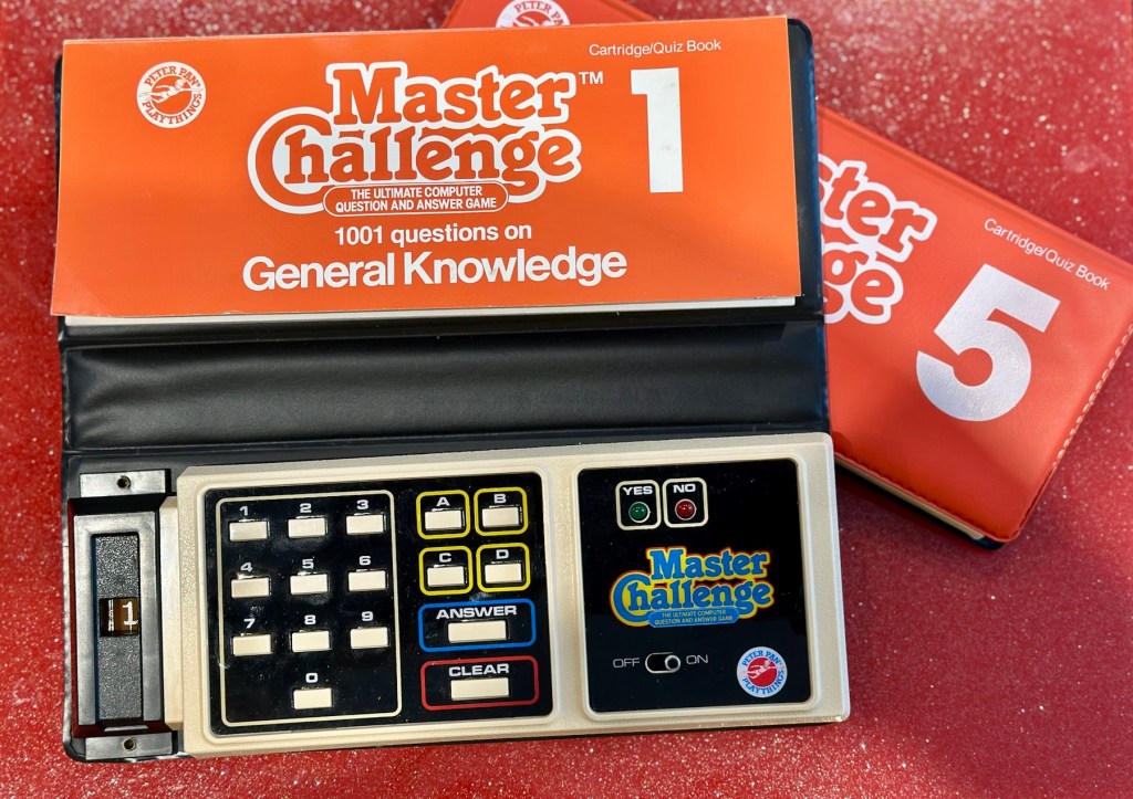
What the listing stated:
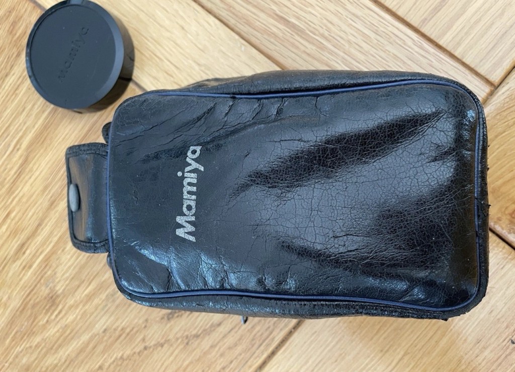
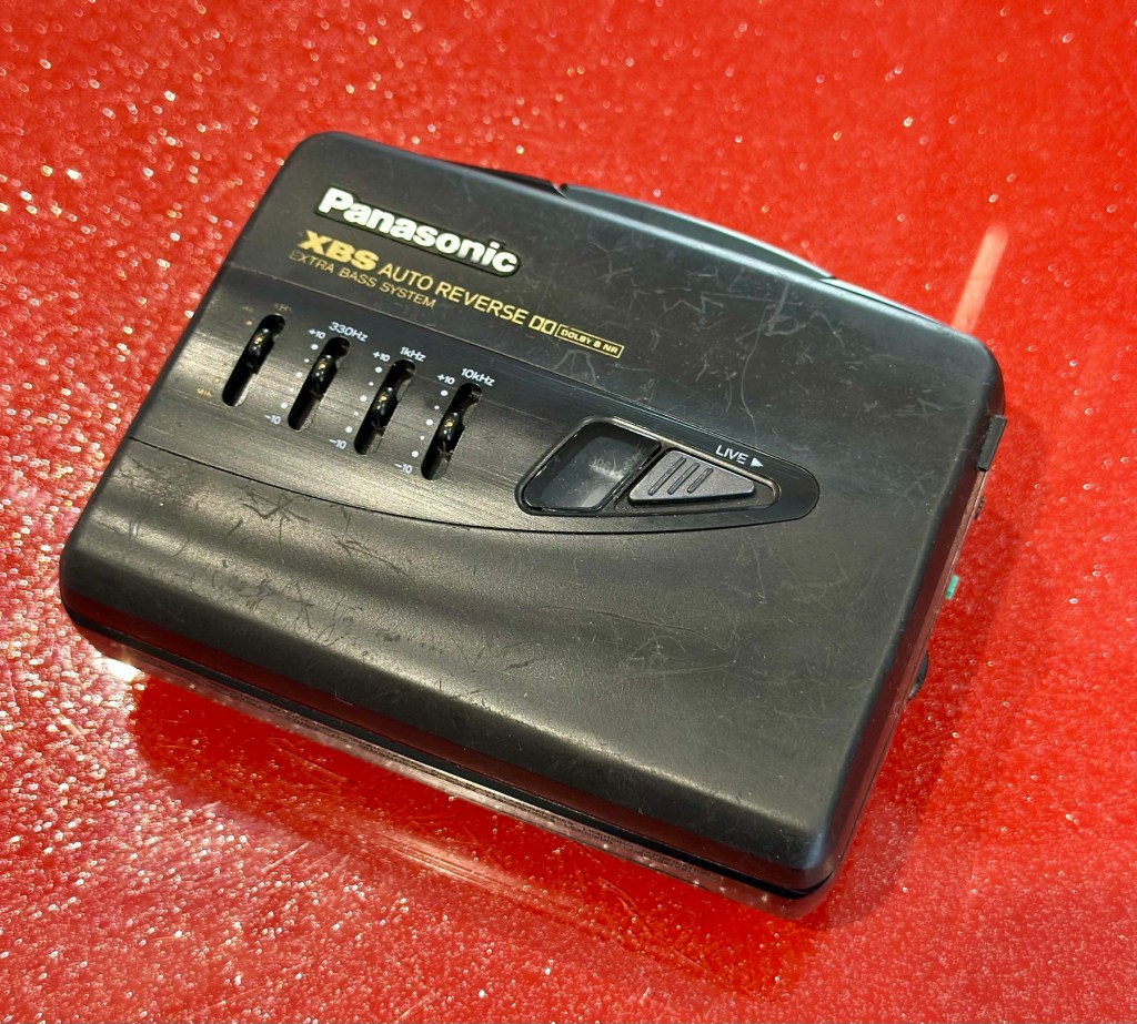
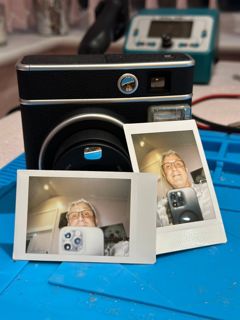
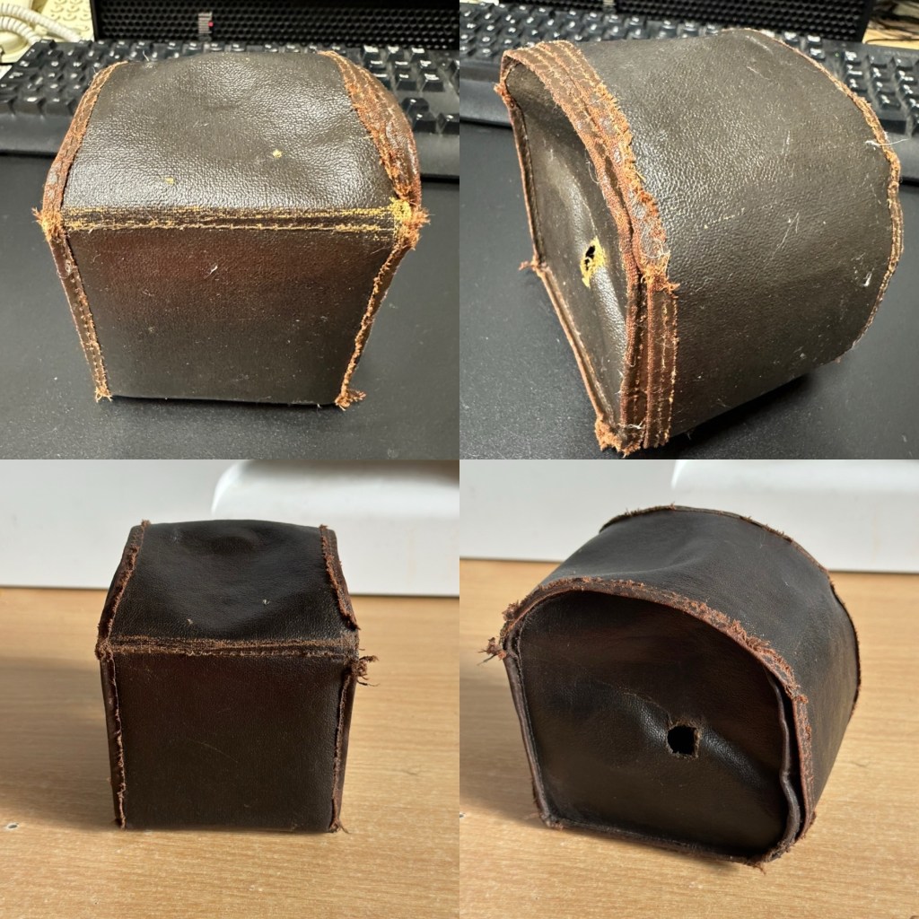
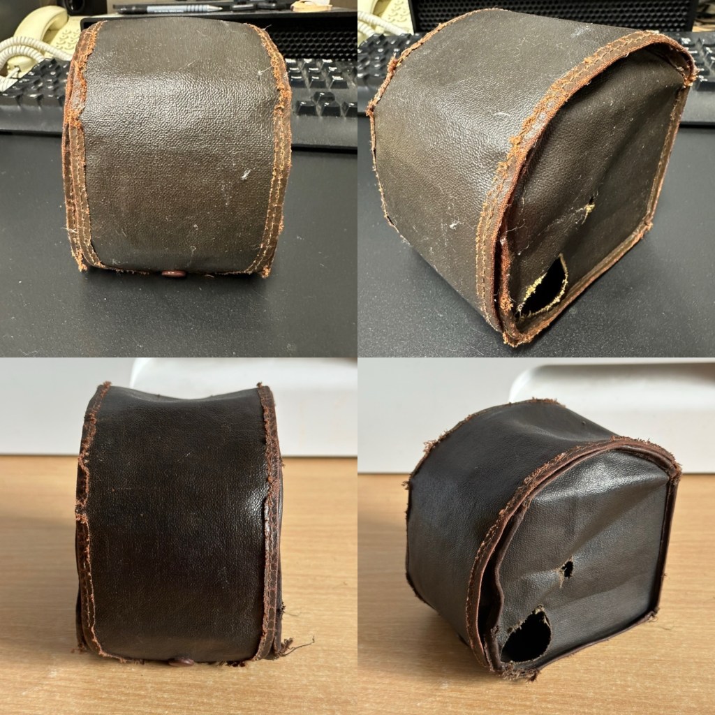
Mamiya M point and shoot camera. It’s in fantastic original condition and is cosmetically excellent with original case and lens cap included. The lens appears to be bright and clear from the front.
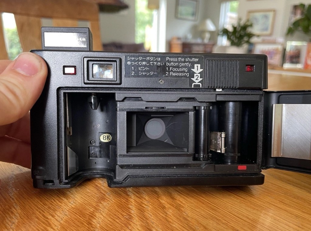
HOWEVER…when batteries are inserted the shutter does not fire and I suspect it is jammed somewhere. The lights come on and it goes “click” but the aperture does not open, nor does the film winding do anything.
For spares or repairs only, I’m sure somebody with the know how could get it up and running again.
Priced super low as I want it shifted and can’t bring myself to bin it!
No returns pleaseEBay


Here’s a little bit about it:
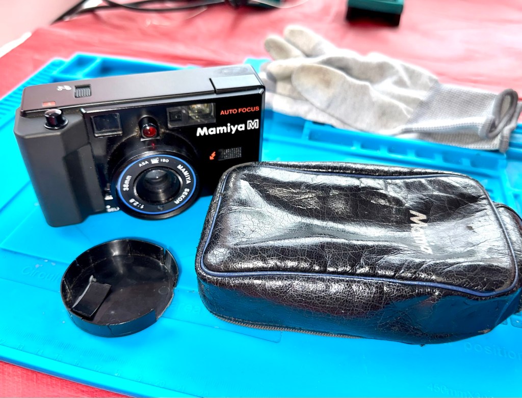
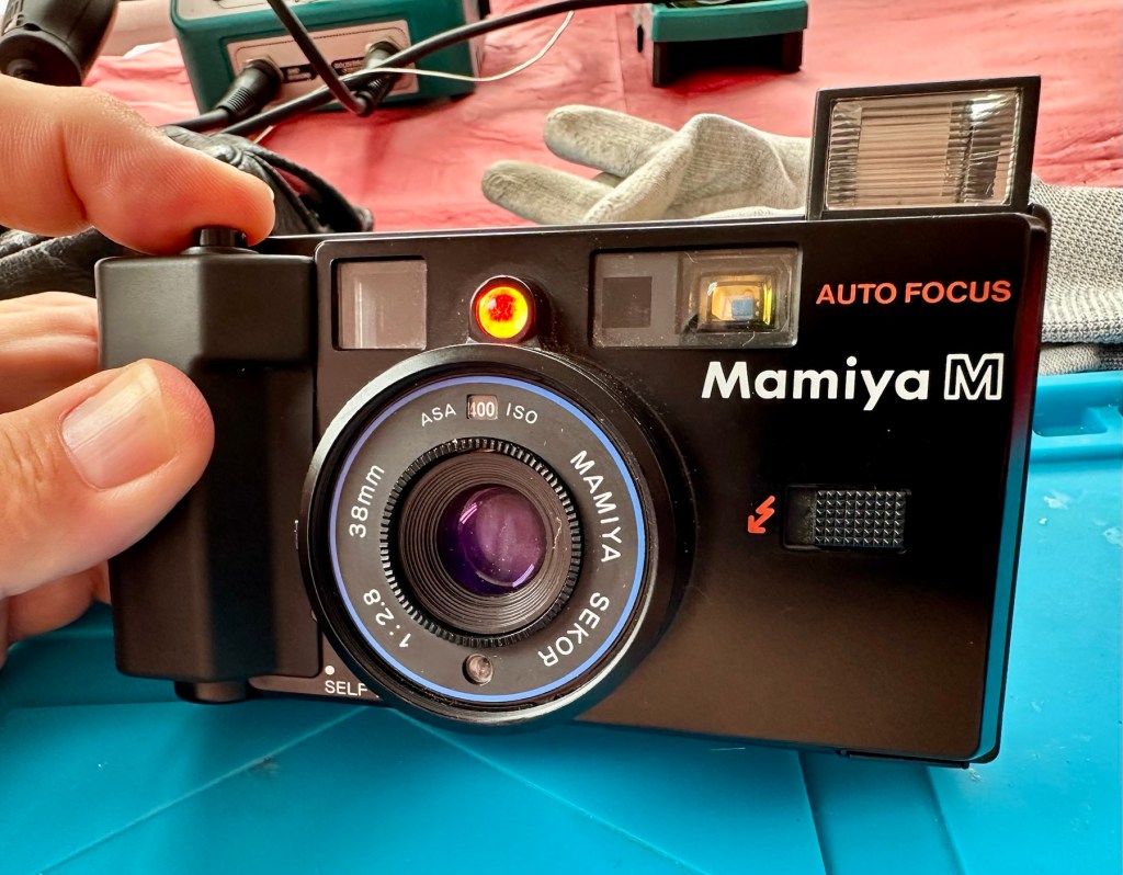
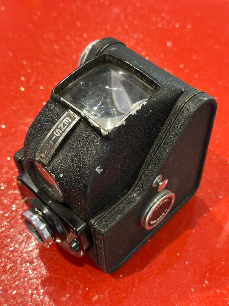
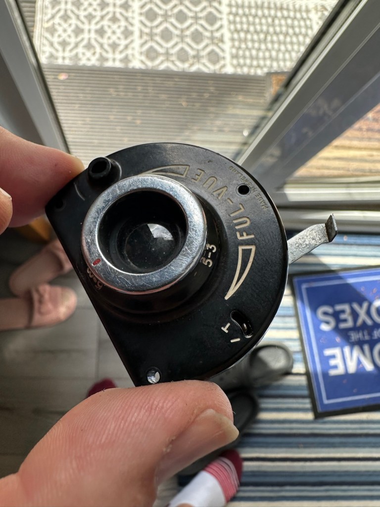
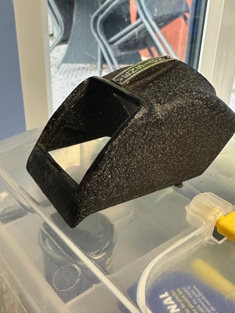
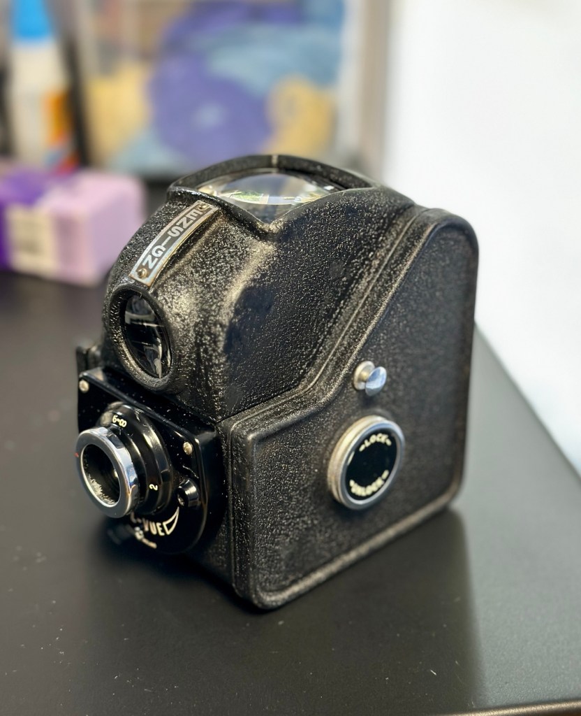
The Mamiya M is a 35mm autofocus compact from 1982. It has a boxy plastic shape, with a fixed Mamiya Sekor 38mm f/2.8 lens. The lens is four elements in three groups. Exposure is fully automatic, based on the film speed, where the ISO is selected via a dial around the lens. Film speed available is 25 – 800 ISO.
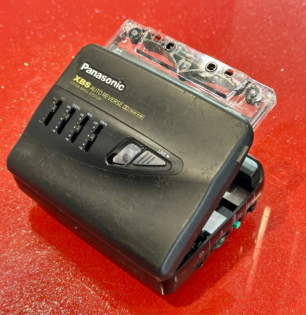
The metering cell is located just under the lens, but within the lens ring. This allows for the metering to take into account any 46mm filter screwed onto the lens. That is assuming it is not a graduated filter. Fastest shutter speed is 1/500thsecond with the slowest at 1/8th. The camera is always on, except when fitted with a specially designed lens cap, which triggers the off state. There is a strategically placed switch it pushes against on the right side of the lens. Most of these caps are lost, including mine.
Photothinking.com
I don’t know what attracted me to this camera, but the fact the seller just wanted rid of it at a cheap price was a starting point. It was advertised as £4:36 GBP and £2:45 delivery, a total of £6:81GBP. I bartered a bit and got it all in for £5:44GBP so I got it a little bit cheaper, a bargain if you like.
Mamiya has a great reputation for building high quality lenses. They were only in the 35mm autofocus point and shoot sector for a short while before immersing themselves totally into the medium format camera market. This 35mm camera was only in production for about a year or so, even though quite a few were produced, we are looking at the low hundreds of thousands, not the many millions, so the camera itself was not a major mass produced and marketed unit. It is a plastic preformed body unit. Known in polite society back in the day as “A plastic fantastic”.
If a Mamiya camera had a blue ring around the lens, specifically on its other models, it denoted a higher quality lens type, it was never confirmed this was the case with these small autofocus 35mm cameras, though many believe it is still the case. Photo quality with these little units was generally of a very high quality.
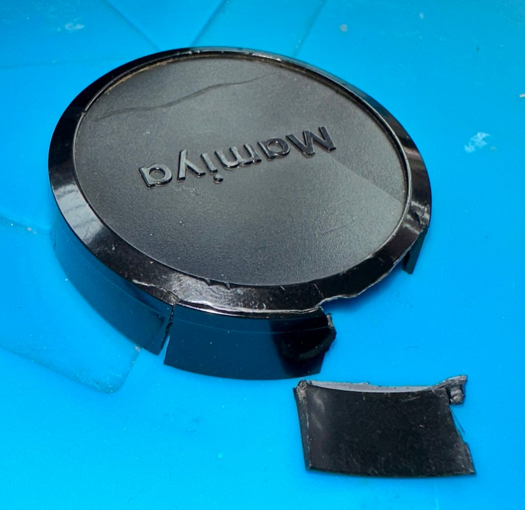
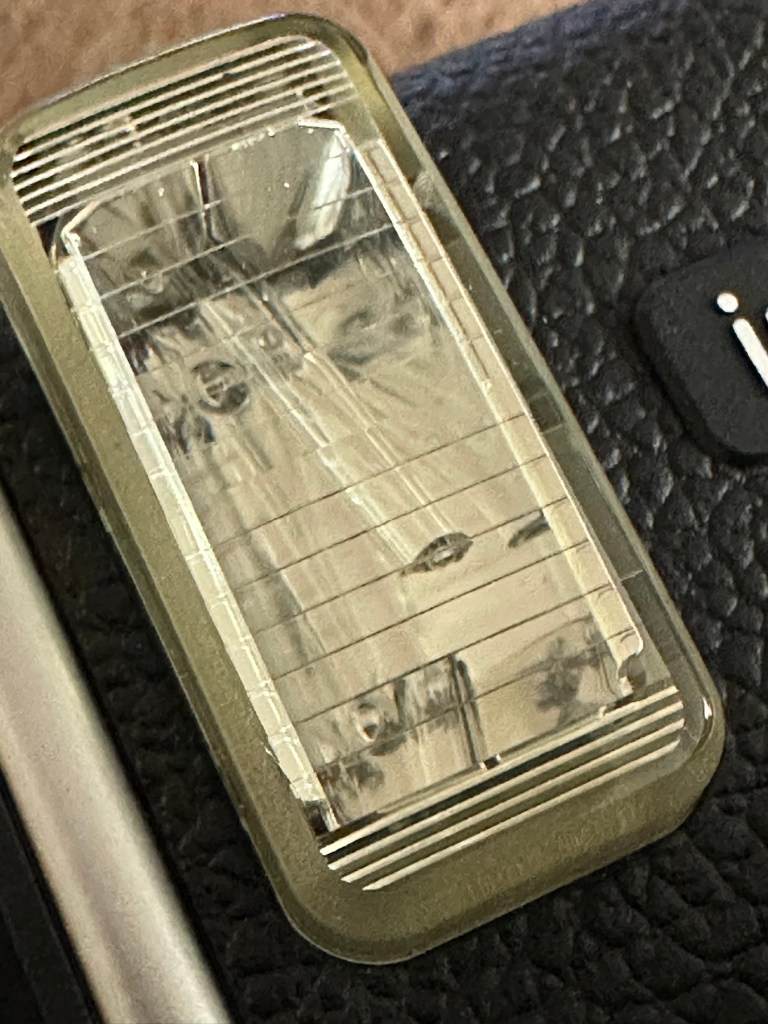
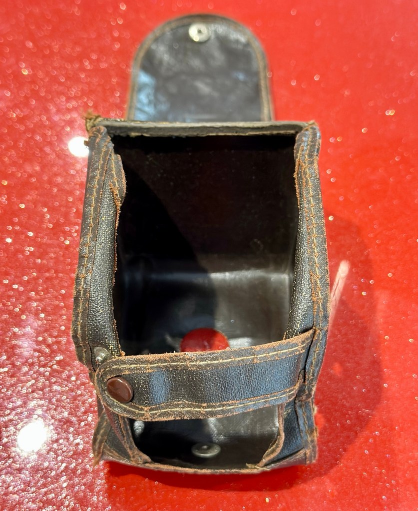
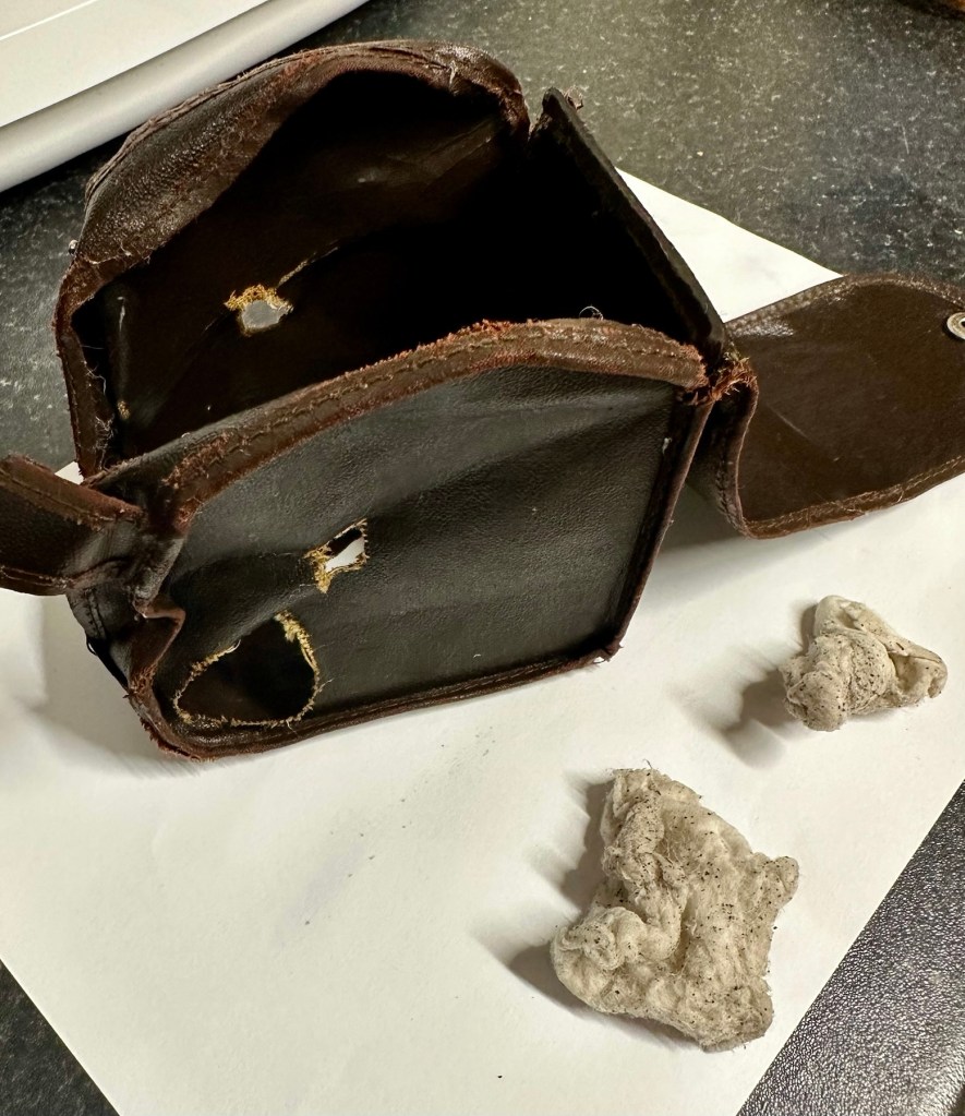
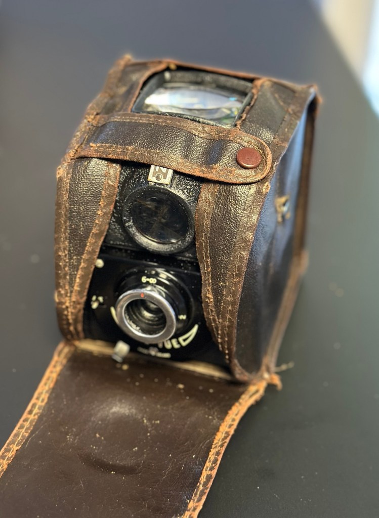
Lens caps with these cameras are very rare, this one has one and it is the original, and i suspect (from what I see in the picture) that there may be a small crack on the side of this one, but that is not an issue. This lens cap is integral to this cameras operation, as when it is placed over the lens, it turns off the camera, without it the camera remains live at all times, and would soon lose its power. It is an early power conserving device if you like. The camera looks to be in overall good condition, probably down to being stored in its original case.
You can view a lot more than I could ever tell you, just by watching this review by Mr.50mm that was posted earlier this year.
Since reading up a little on these cameras it appears that I may well have bagged a bargain, if it ever works. And I also believe the seller may well again be unaware of the operation of this camera and it may in fact be working just fine? Who knows? I have my suspicions but we will just have to wait until it gets here for assessment.
Below are some sale prices relative to this camera model that are currently selling on EBay, some extremely high prices compared to what I have paid today:

It’s plastic and so 80’s. And people obviously loved it. I’d like to be able to get this camera working again, and would love to run a roll of film through it to give it a test run. But first I have to assess it and see just what is wrong with it. I have a roll of old film available to test its “faulty” rewind system, and I have all my tools ready to crack it open and get inside, if I have to. So let’s get at it….
Assessment:
It’s arrived and I must say it is in an excellent cosmetic condition, probably down to being kept in its original Mamiya soft case. The lens cap I thought had a crack in, is actually broken, probably beyond reasonable repair, but at the moment that is not important. Let’s put that to one side for now.
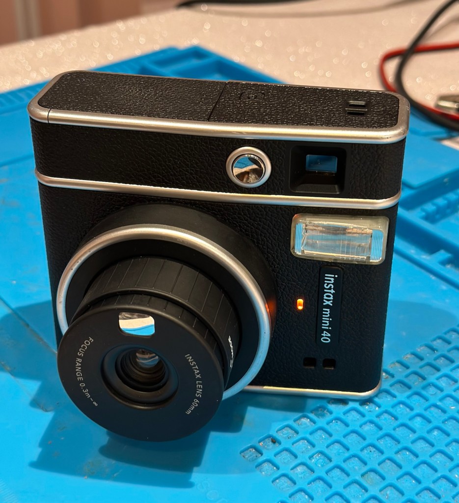
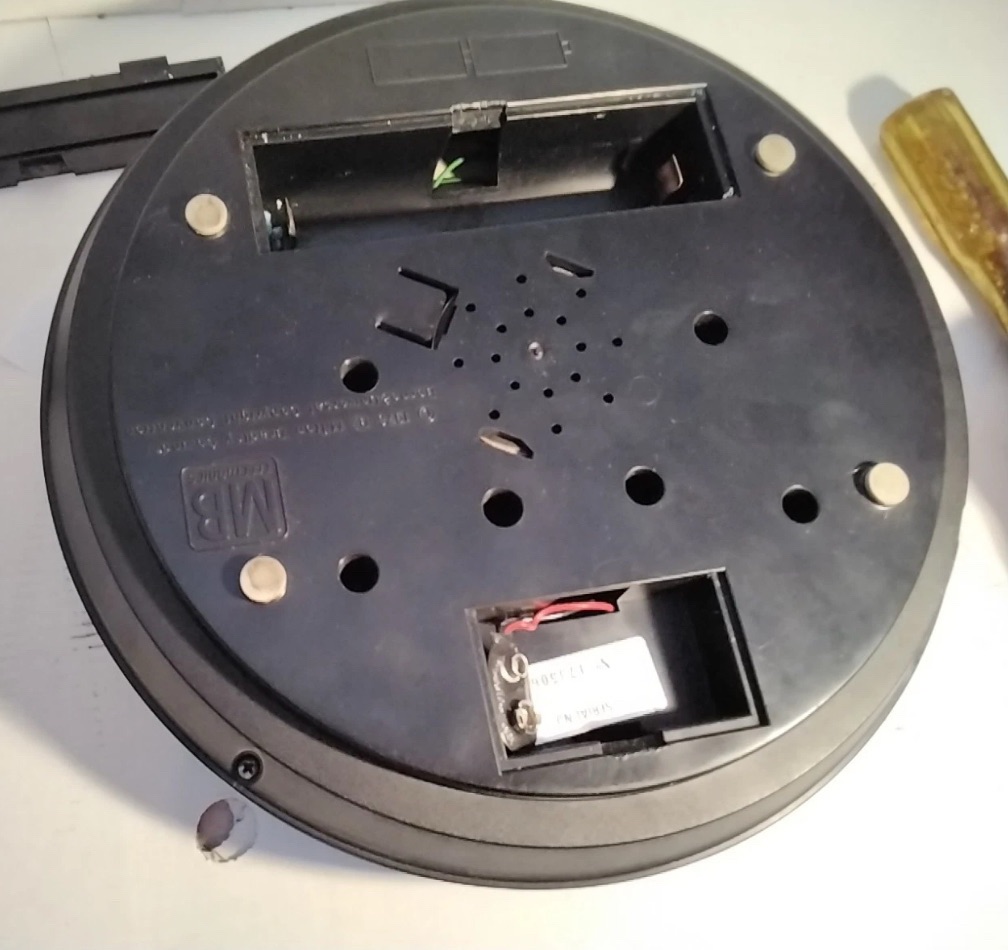
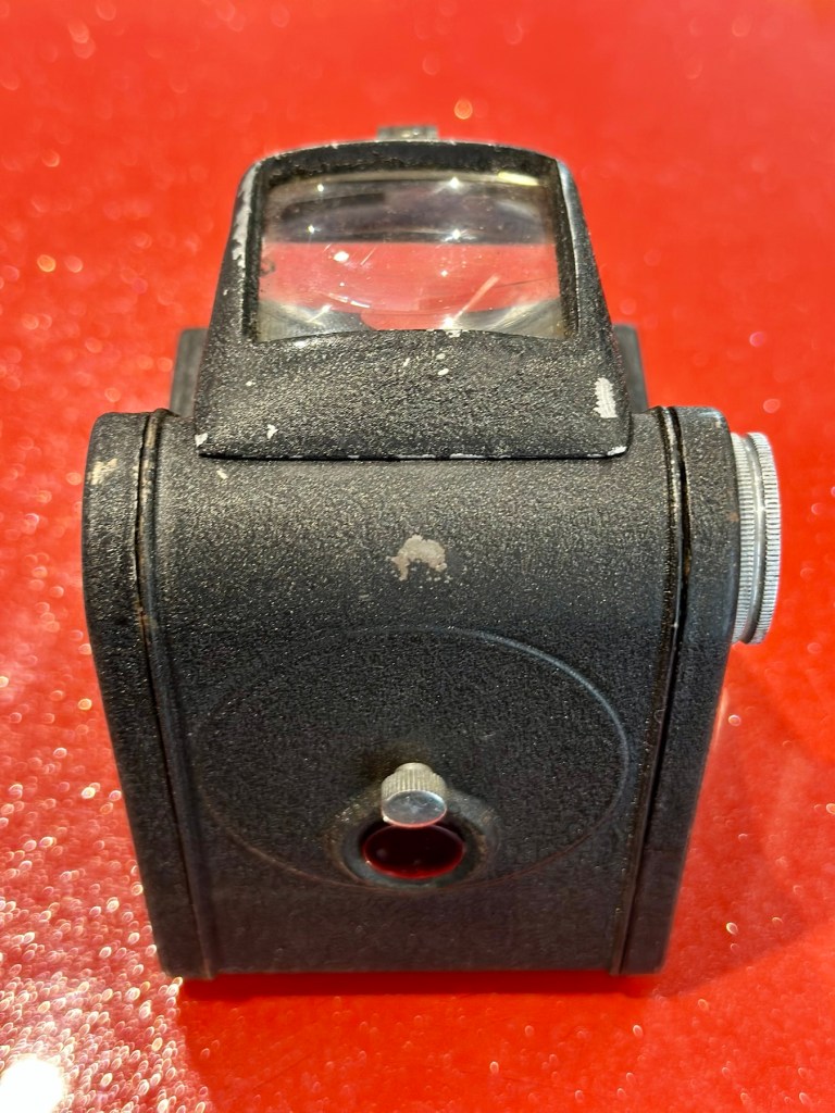
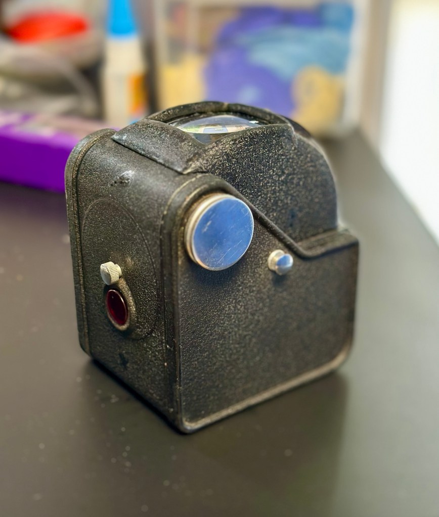
The actual camera is partially alive. When batteries are installed there is a red light that appears on the right rear side of the camera, this is the film transport light and should extinguish when transport is complete. The flash switch sticks a little, and when the flash is clicked into position the distance sensor light on the lens activates however the flash does not charge. The winding system is inoperative and does not auto wind at all. The shutter does not operate, despite the shutter leaves being able to move when gently coaxed.


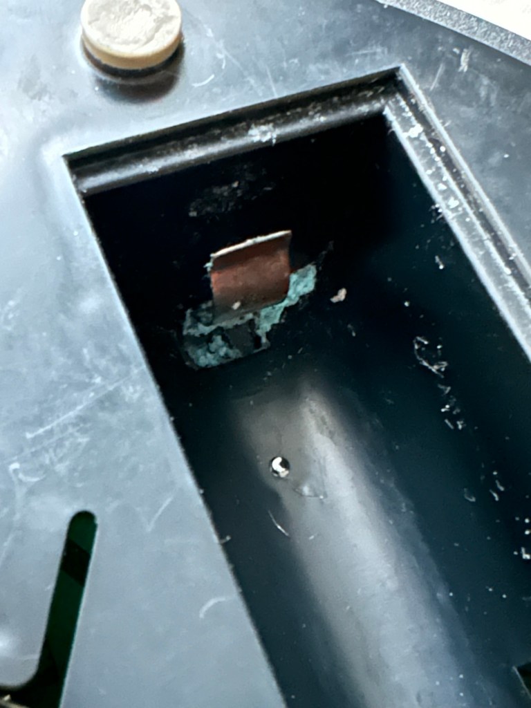
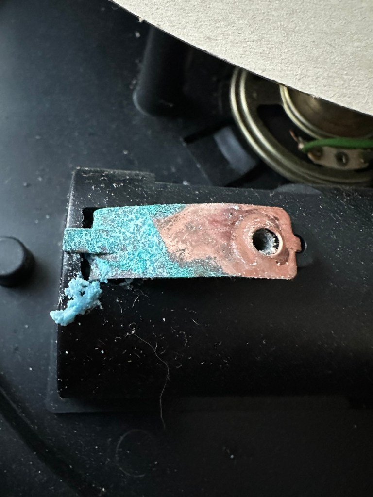
There seems to be partial electricity throughout, this could very well be the issue. There just doesn’t seem to be a uniform continuity throughout the camera. This will need to be looked at. Something very weird is going on inside.
Repair:
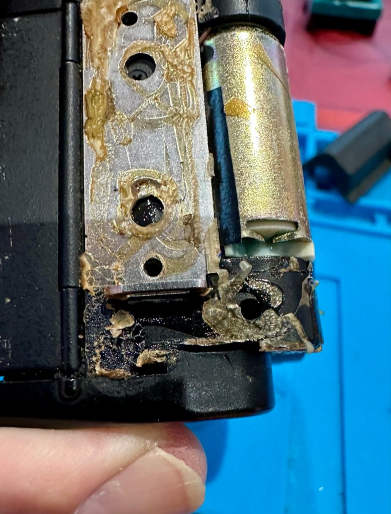
I’m really annoyed, closer inspection shows there are 6 screws missing and someone has been inside this camera prior to me. Again I think I’ve been stung by the EBay curse of “Spares and repairs- no returns” will I ever learn?
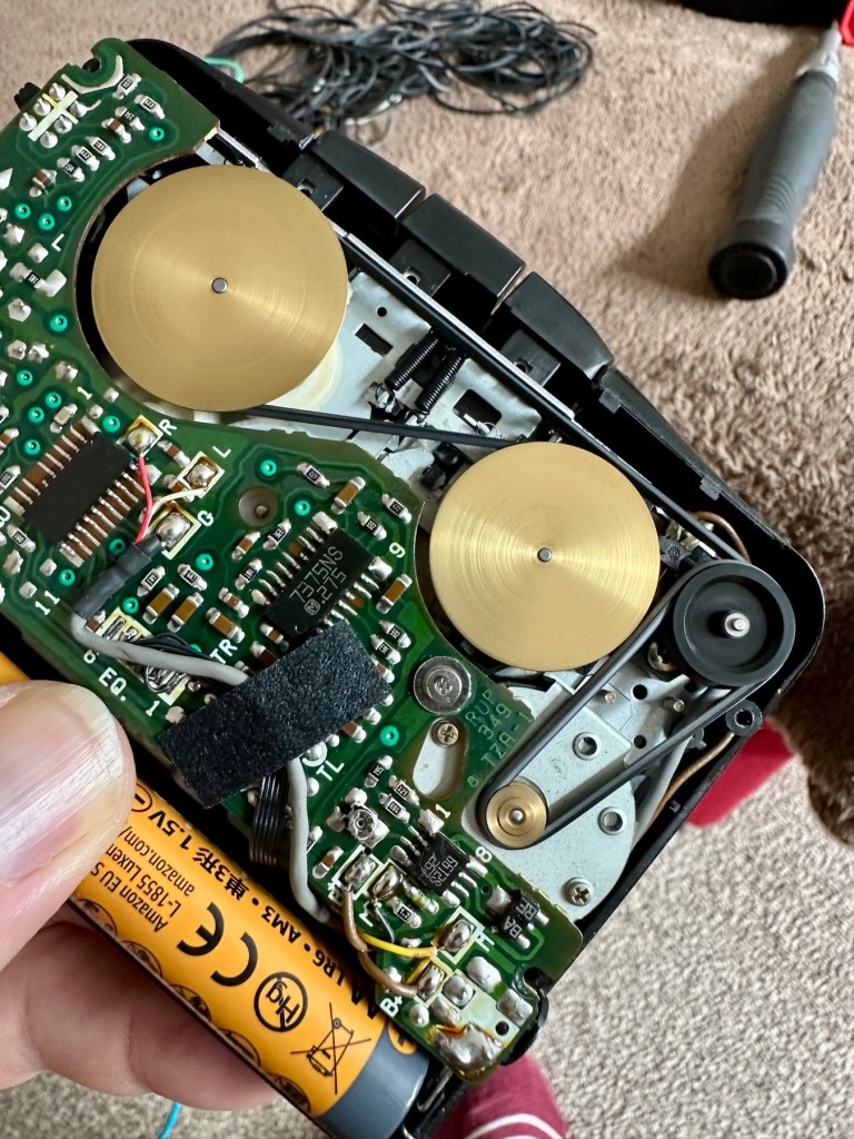
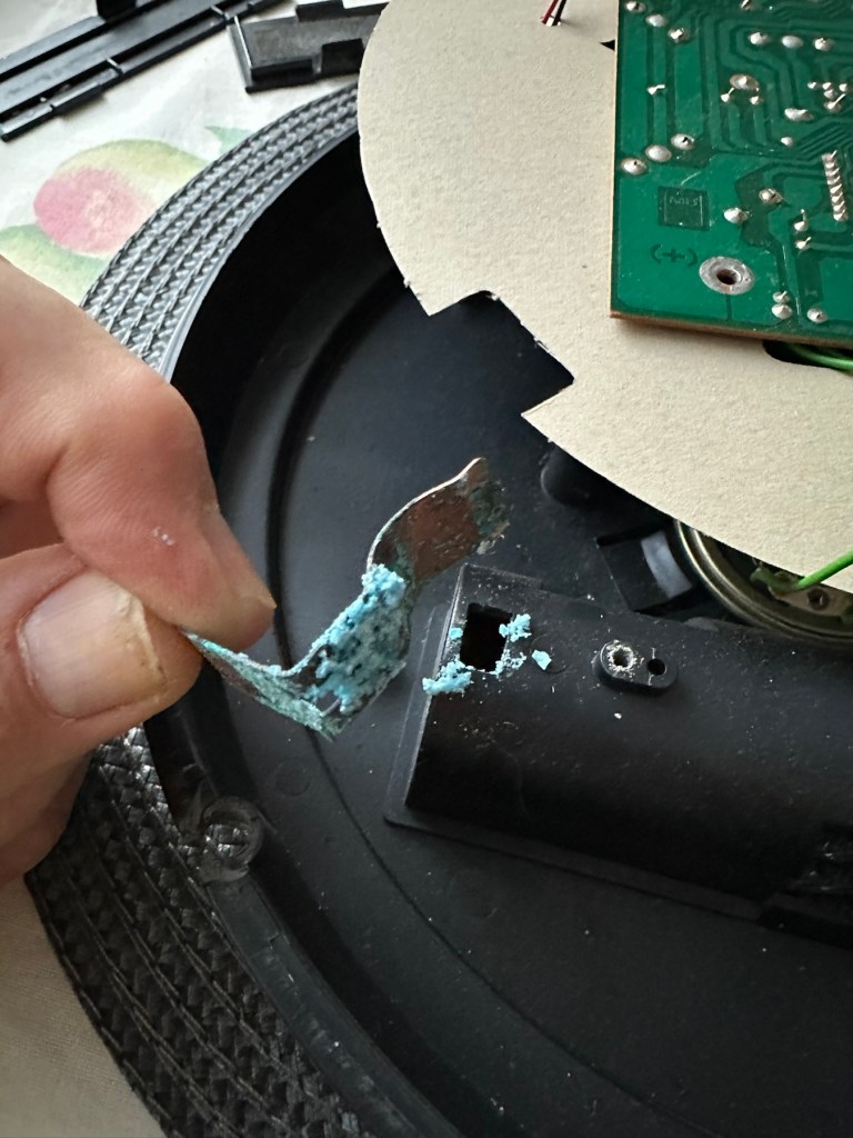
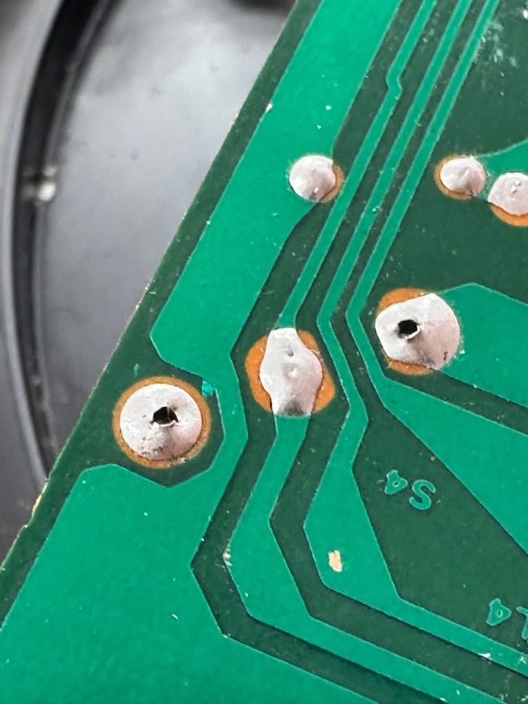
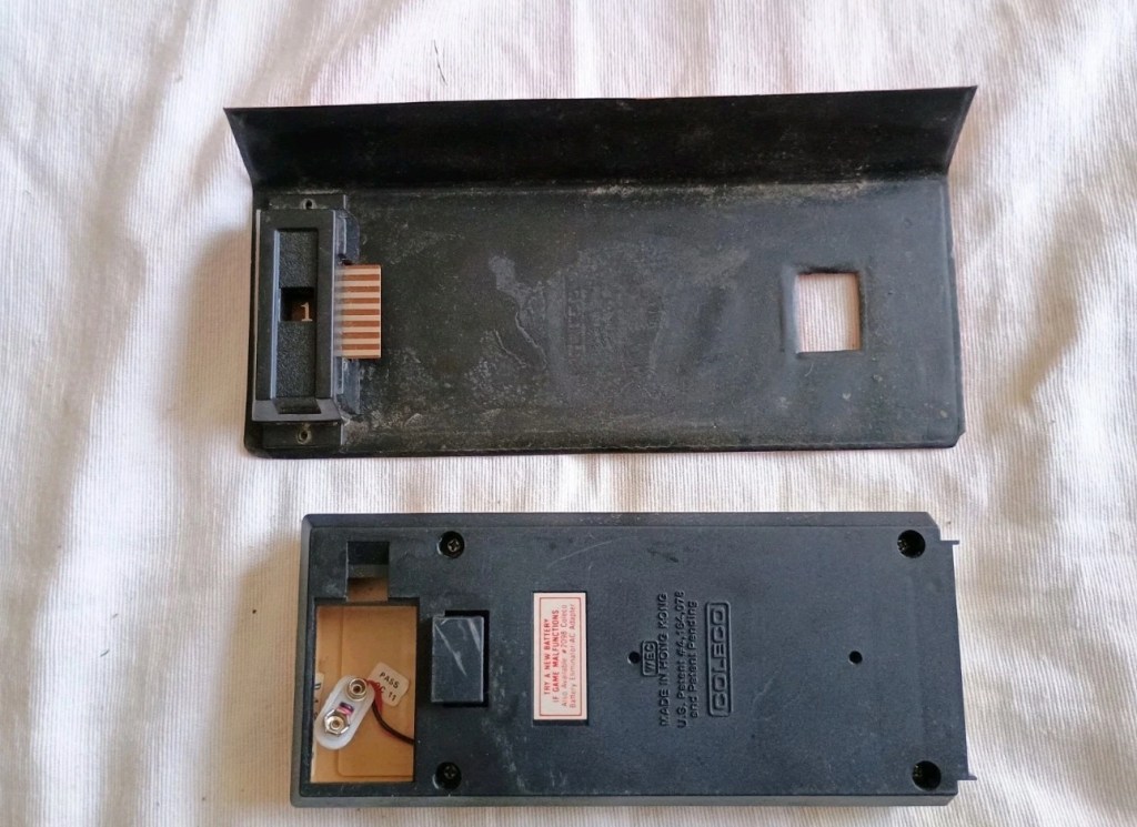
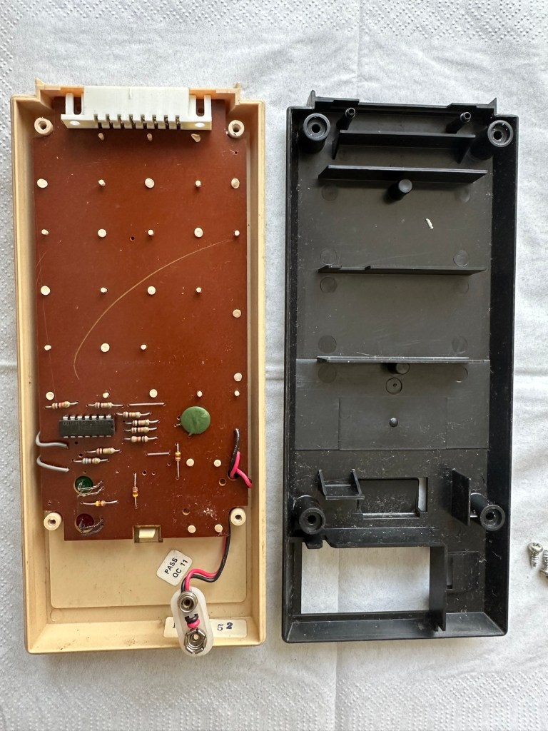
I’ve removed the remaining screws, and had to peel off the rubber grip to access and expose the motor and associated component board in this area. There will need to be a lot of cleaning here before gluing it all back in place.


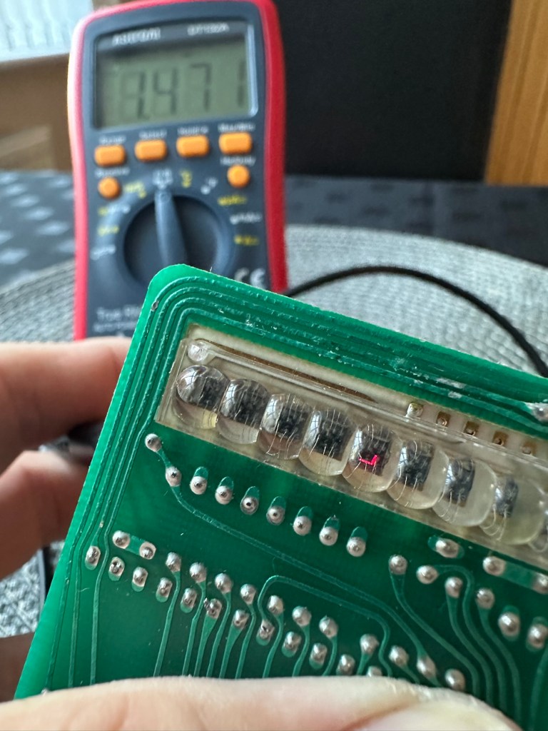
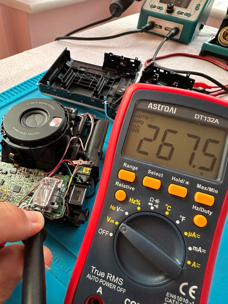
I’ve managed to get the flash charging light illuminated, and a current of 214v in the flash confirms that the Flash capacitor is holding a charge and more importantly, receiving a charge from the battery circuit. But I cannot get it to fire. There seems to be an issue with the shutter mechanism and the related electrical circuit in this area. The motor is not working, it’s either dead or not receiving power. I need to look in this area a little more thoroughly.
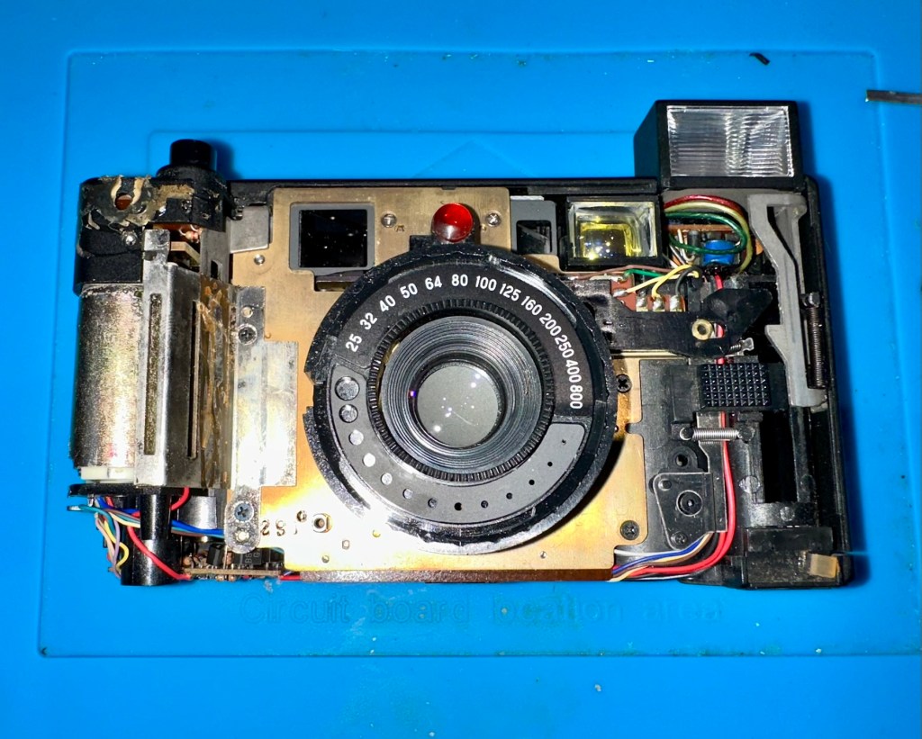
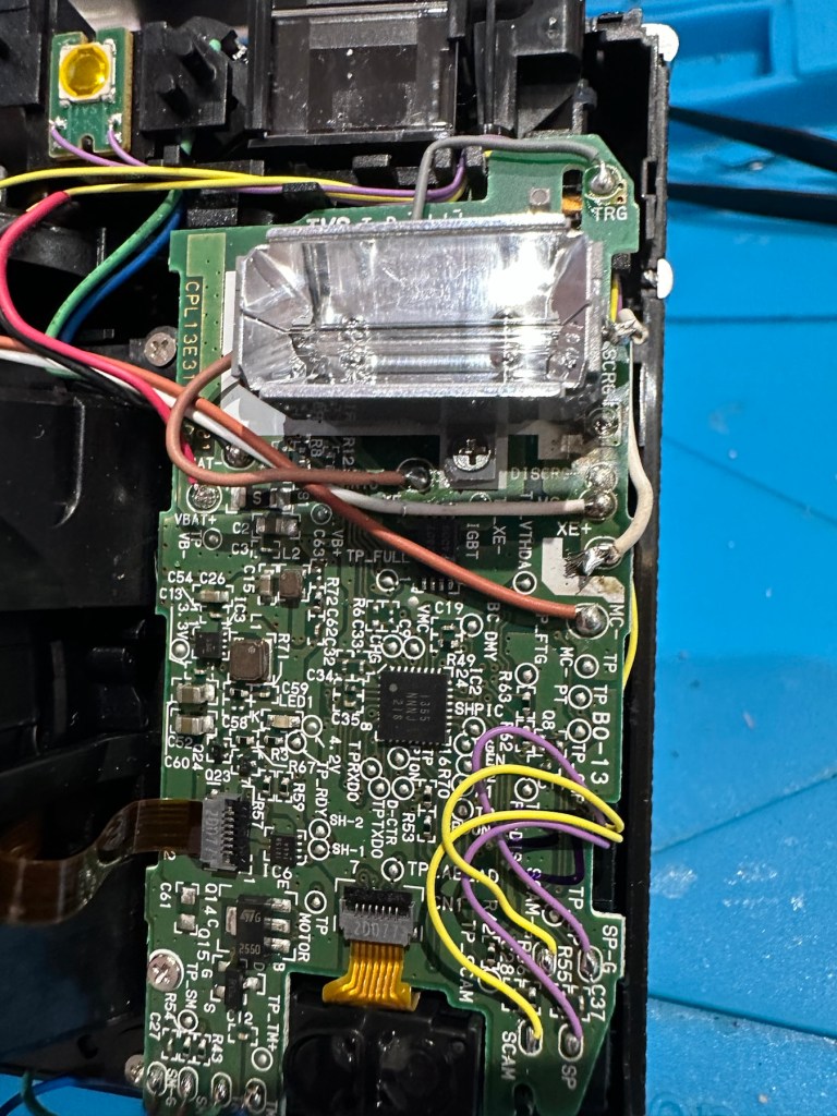
I’ve now removed the front fascia and now have a good view of the overall workings inside the camera.


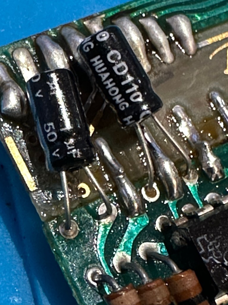
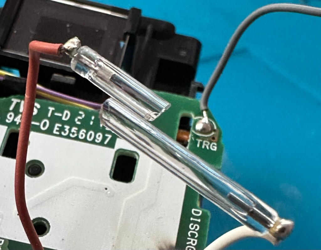
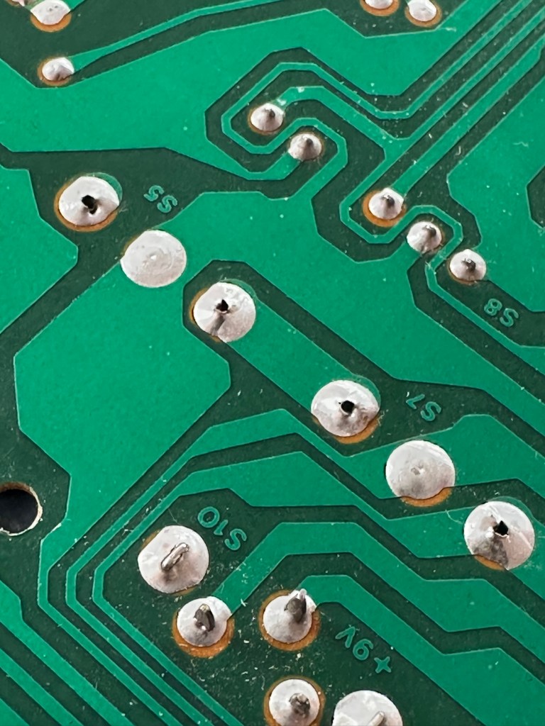
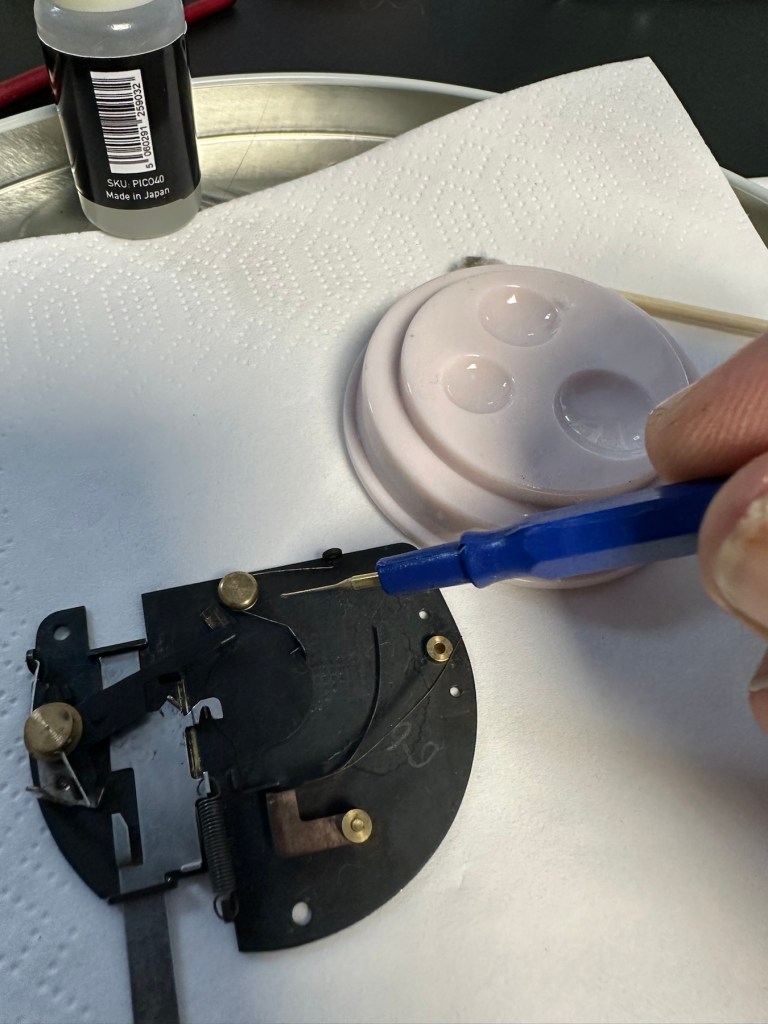
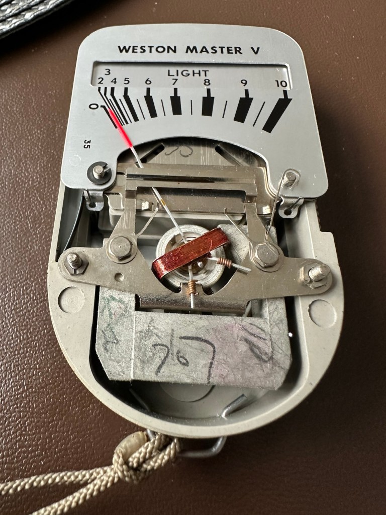
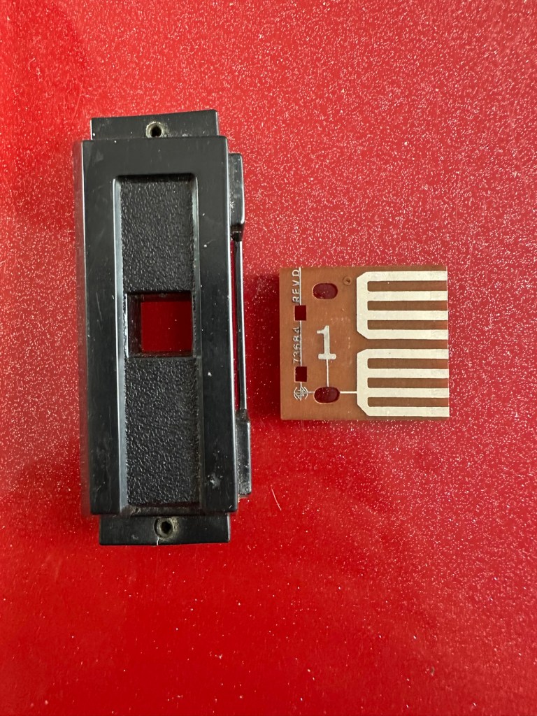
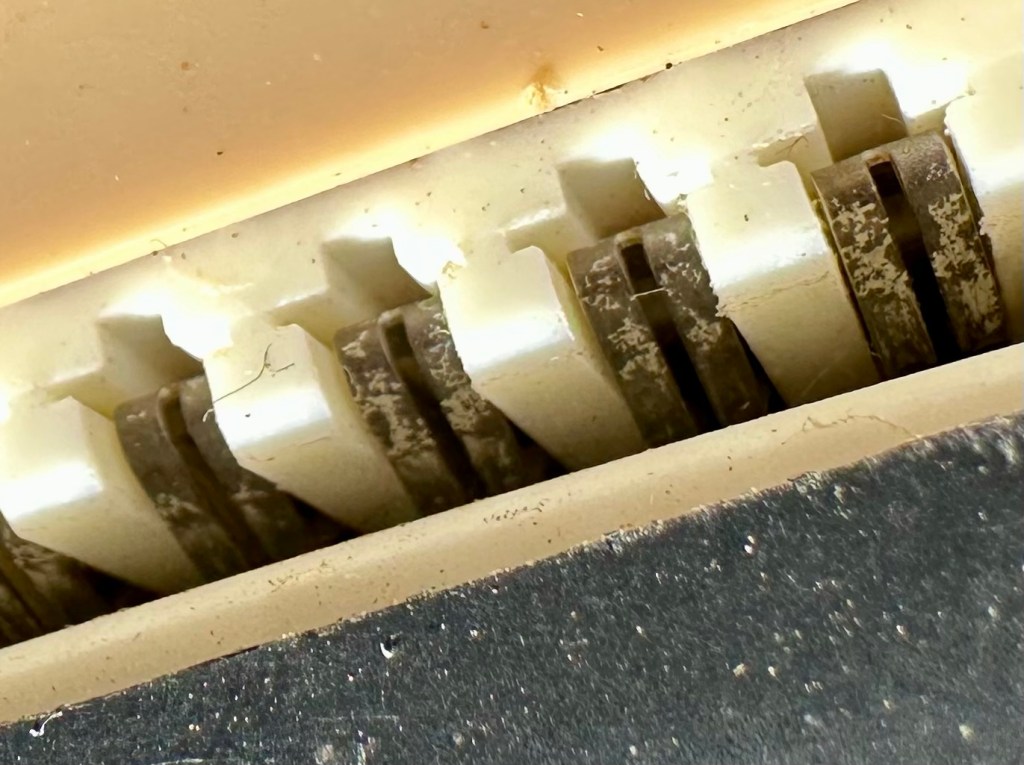
Ive taken out the lens and the leaf shutter, these seem ok and are working freely when operated. To me it looks as if the mechanism that triggers the leaf shutter is either seized or the variable capacitance system located at the top of the camera, that is basically just a needle on a circuit board connected to the focus light, could be at fault, it does not freely move on each camera actuation as it should, and this is not a readily available part.

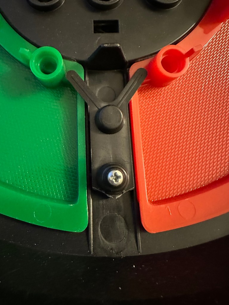
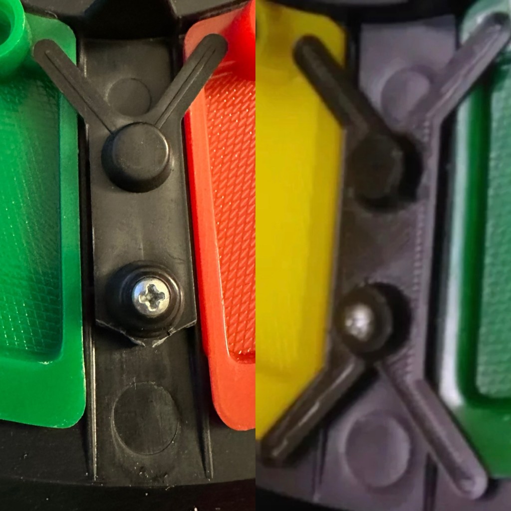
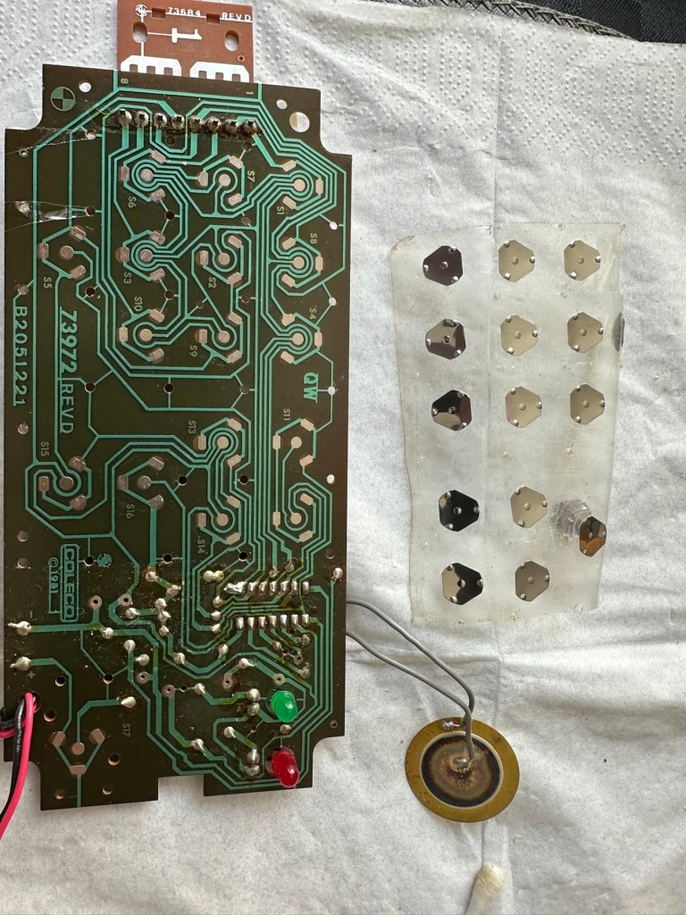
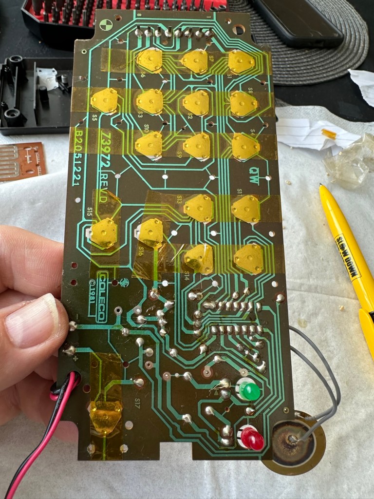
It seems the deeper I delve into this camera that I am finding more issues, and I’ve just found two parts that are incorrectly installed that are on a cog system connected to the motor. I’m fighting a losing battle as it appears the person who has been here before has probably added to the issues of this camera in their attempt to fix the original issue.
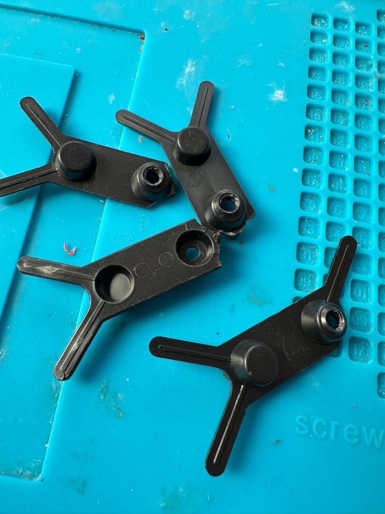
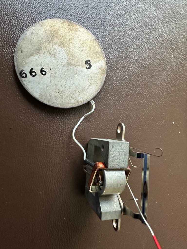
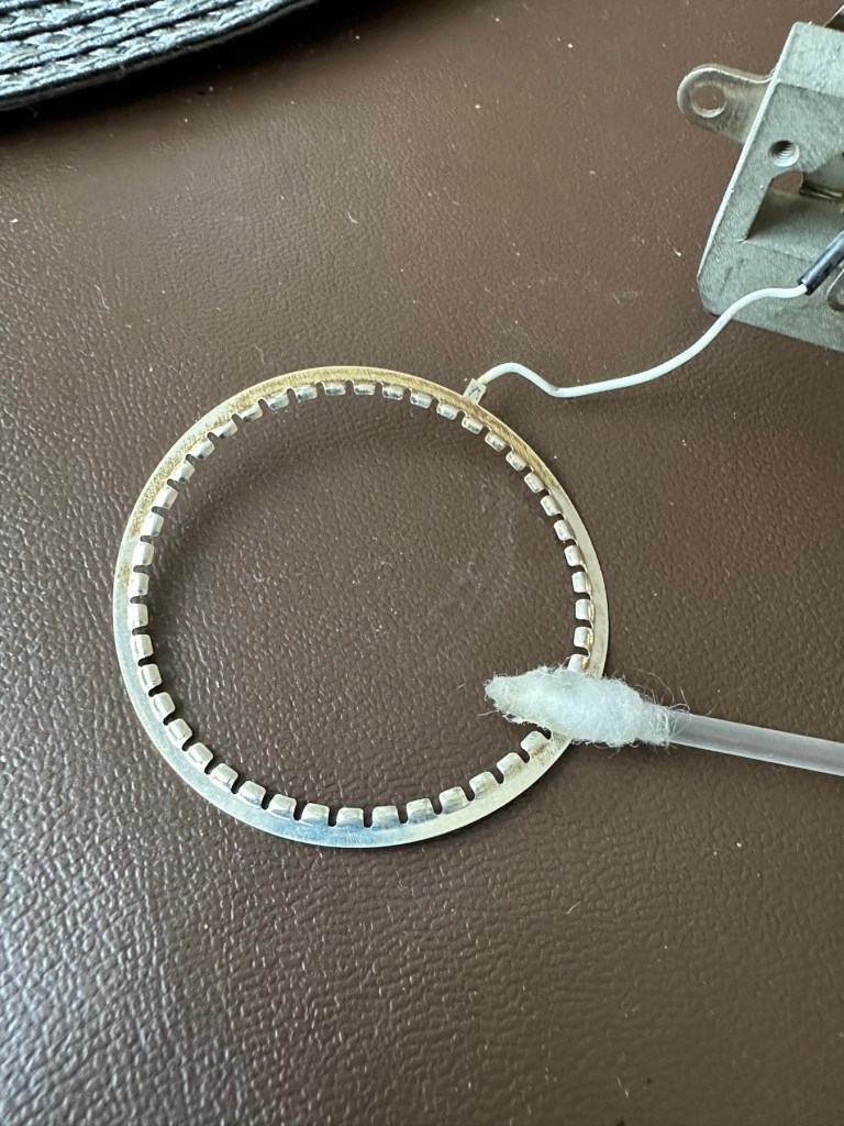
On top of the missing screws I’ve now found a missing capstan cog related to the leaf mechanism that would help explain a certain lack of movement in areas. The motor is dead, I’ve taken it out and used the bench power supply and it is non responsive. Even after spraying with some contact cleaning fluid and sitting there spinning the axis to get the solution absorbed, there is still no response. It’s totally dead and will require replacement.
Result:
Well. Once again I have been mislead by incorrect descriptions on the auction sites. It’s a shame really as this is a lovely camera and if it had not been tampered with inside, I’d probably be posting a different review today, one that would be more positive. With screws, cams and cogs missing I was pretty much set up to fail here.


I’ve reassembled the camera and it is now back in its pouch. The positives are that I have learned a lot about how this camera operates, and just dismantling and reassembling the camera allows you to learn a lot about it, and the technology used during that period in time. All the screws that I removed have gone back into place with none leftover, yet another positive.
So it’s a failure I’m afraid, but it will be kept and either used as spares or I will obtain a suitable donor to get this one up and running, it will not be disposed of in any way. It will be reused. I’ve only paid a small amount for this, it’s worth it for the spares alone.
I have already set up a notification on the auction sites for when another suitable camera becomes available. I will update this post or post a new one that incorporates either the repair of this unit or its use as a spare parts donor, when that time comes.
Thanks for passing by. Its appreciated.


You must be logged in to post a comment.