

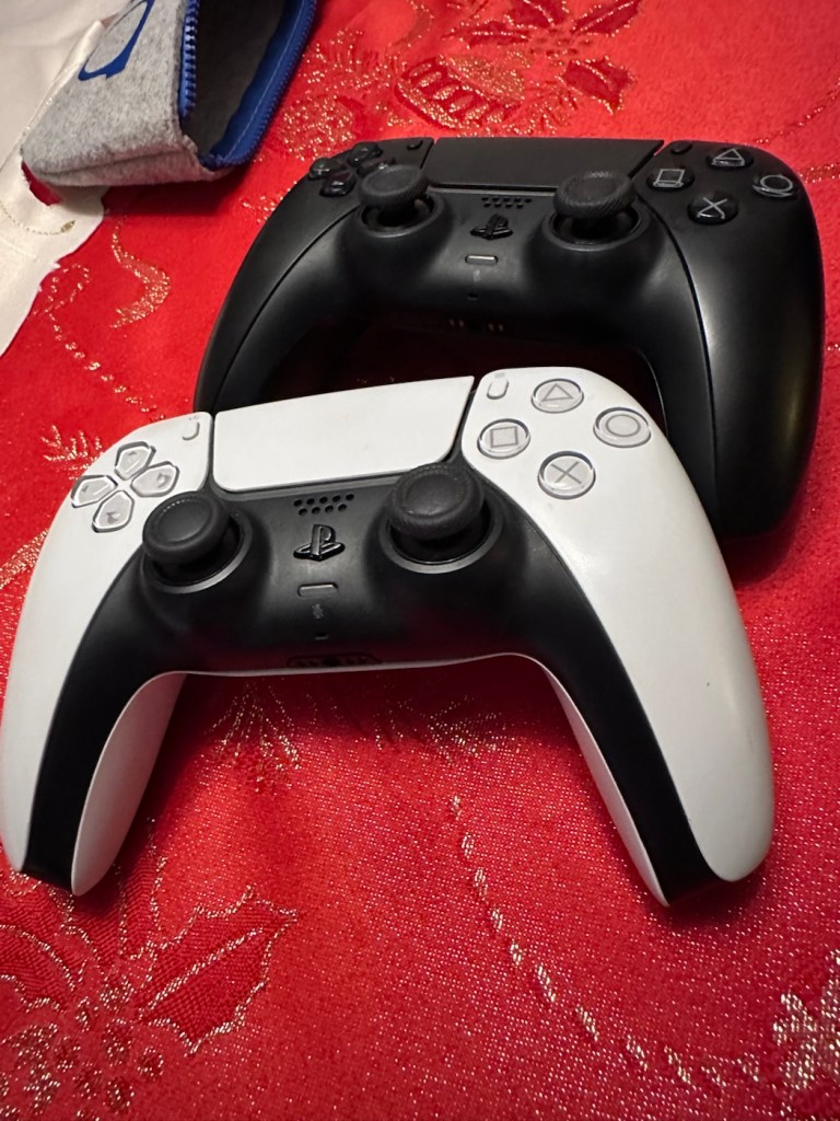
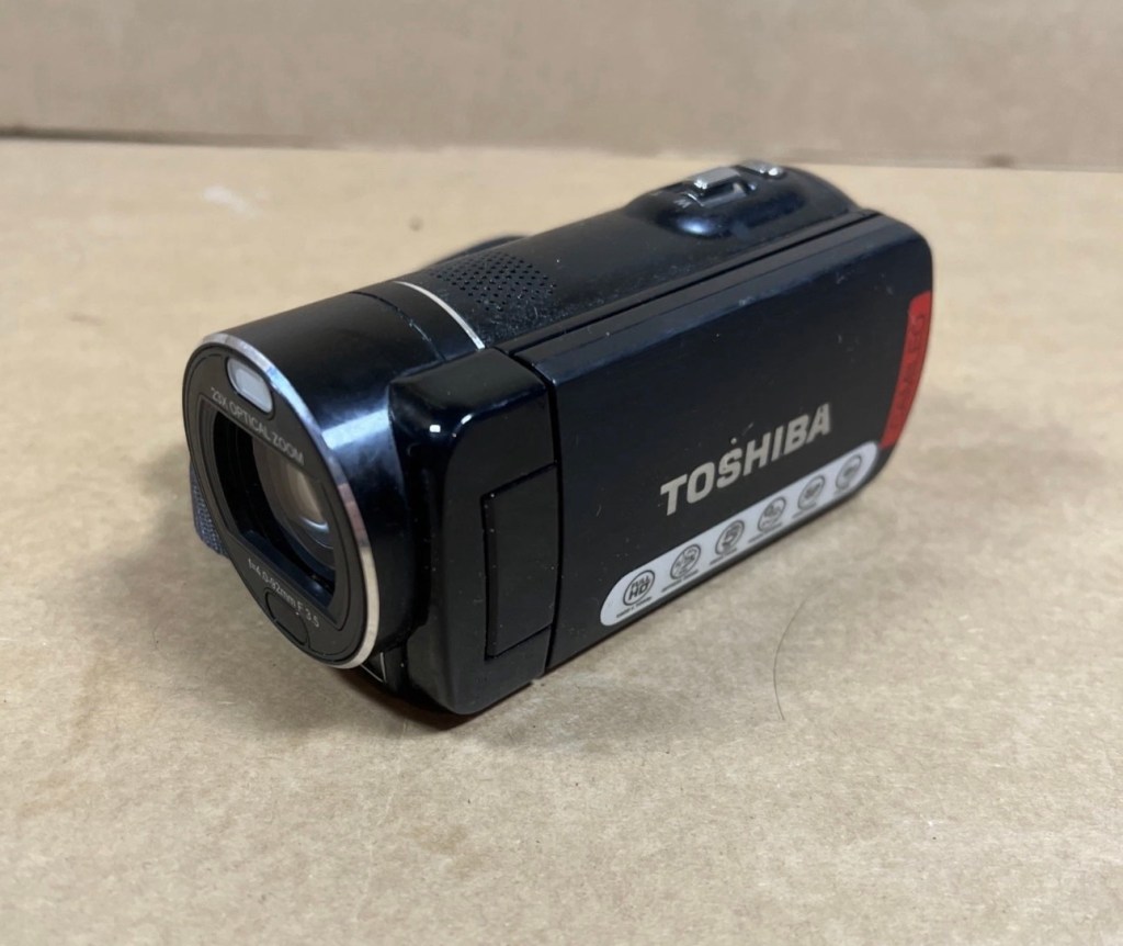
It’s great when one of the youngsters of the clan come up to you at a family gathering and greet you thus, “Oi, uncle Dave, have a look at this for us will you?” and then they just disappear into the crowd as I’m now holding a couple of items I’ve never been exposed to before, in this instance a pair of Playstation 5 Dual sense controllers. (I had to google to find out what they were!)
Apparently they don’t work, or are having difficulties, and it’s now down to me to find out what’s wrong.
Now I’m not a gamer in the true sense of the word. I like, and have repaired and own a good few hand held devices that have been featured within these blog pages, but I do not own a console, I never have. However I’m lucky in that I know a few people who do have these consoles, who I can go to and test how they are behaving, but the good thing is that these controllers can also be tested without a games console and just require a computer with a USB port, and I do have one of them, a clever move by the manufacturer me thinks.
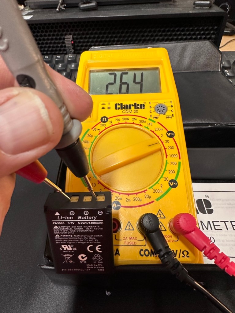
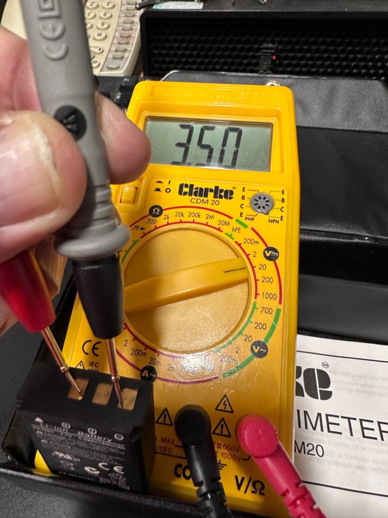
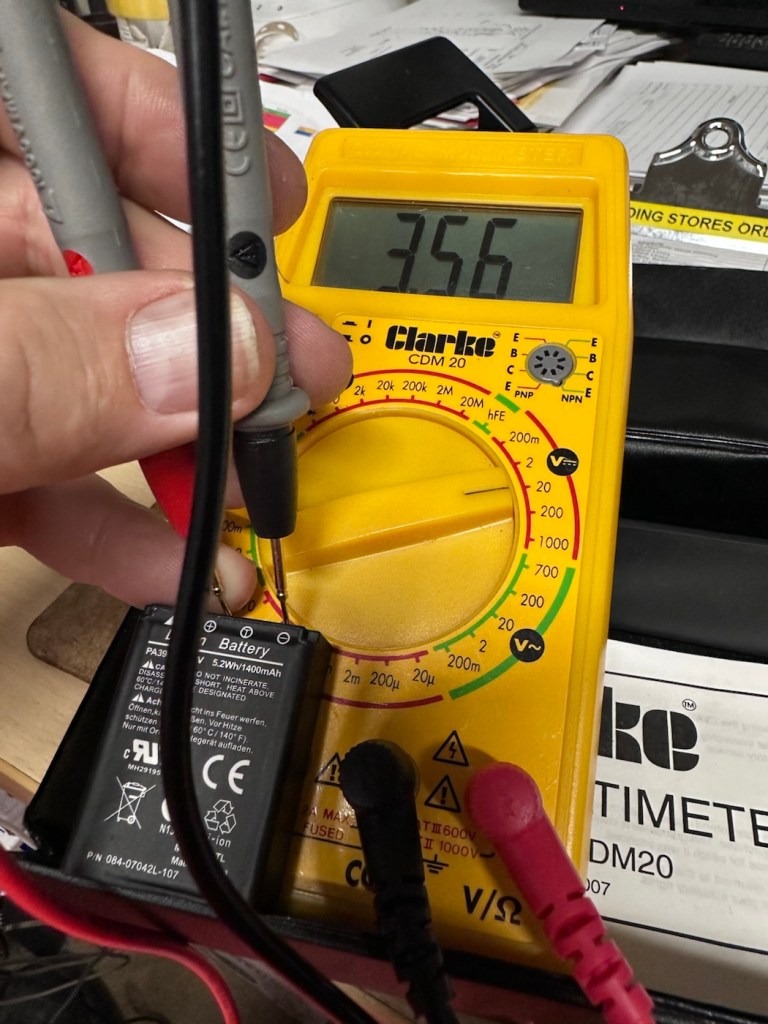
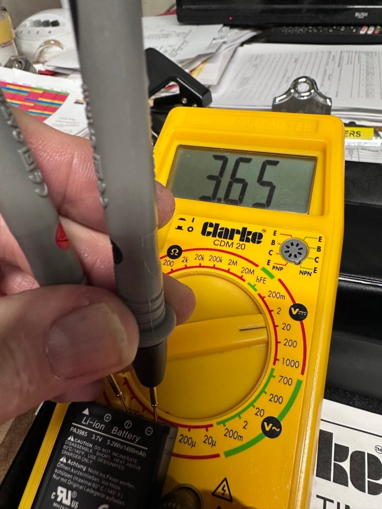
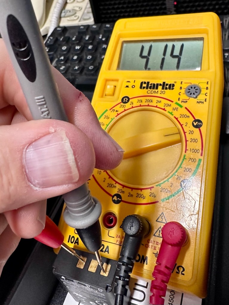
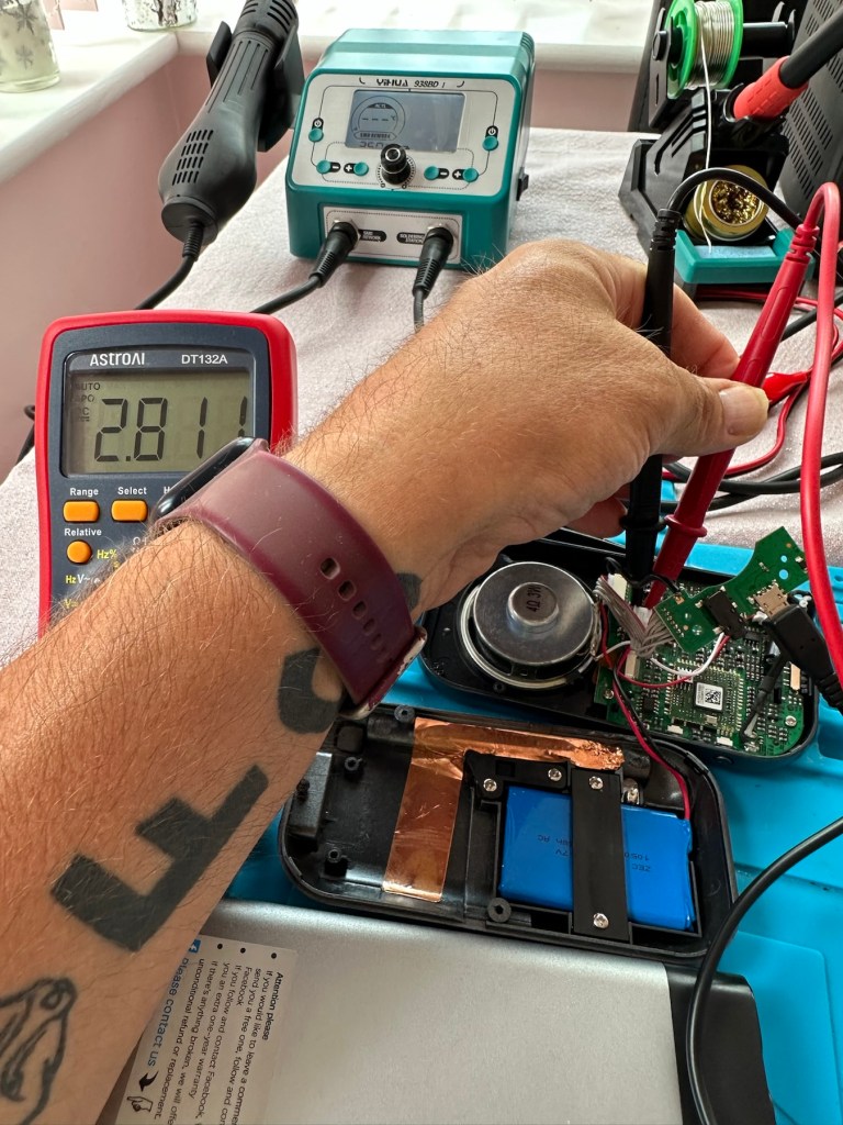
First thing I did here was to plug them in to a USB supply to charge the onboard battery. Each one has a 3.7v rechargeable battery that should give between 6-12 hrs of activity depending on how vigorously the unit is being used. When charging it glows on and off orange until it is charged and then the glowing just stops. Both these units took about 2.5 hrs to fully charge, and they seem to both be holding a good charge seeing one of them, the black version has not been used for some time.
Let’s get them connected up to a PC.
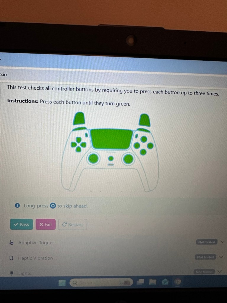
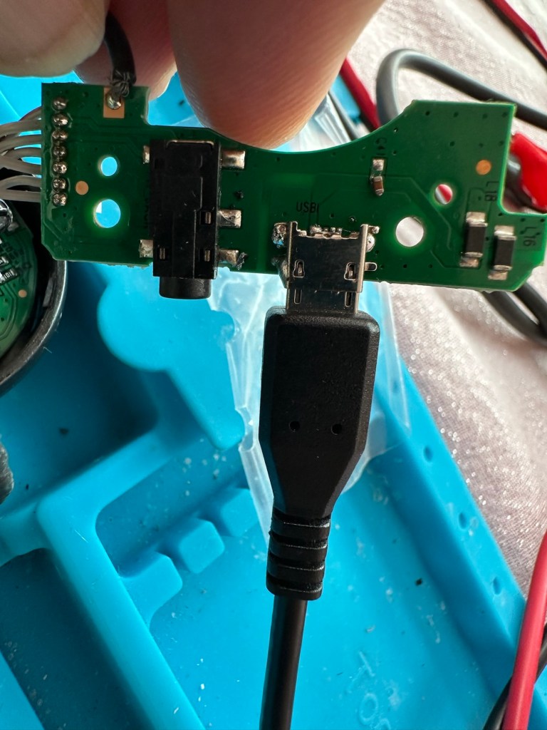
A simple good quality USB cable is the communication method between the controller and the PC. Next, you go to the address: https://dualshock-tools.github.io and here is where you will be doing those checks on the controller that sits in your hand. Seeing I don’t really know what’s wrong with the controllers I have been trusted with, I think this is the best place for me to start my investigation as the site does do some good, and thorough testing.
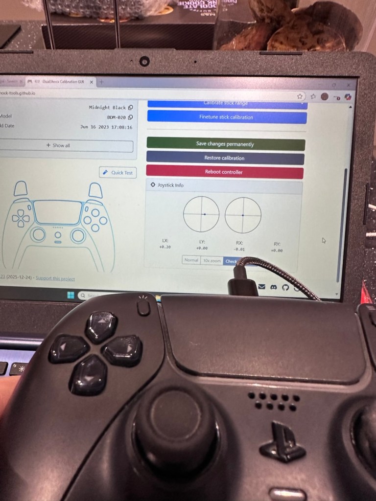
I have two controllers to check so I start by plugging in the Black controller, clicking connect on the screen gets access into the memory of your controller and all the firmware detail and build date is displayed in front of you. Cool!
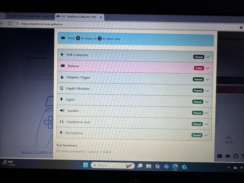
Just under where this information is displayed we enter the first series of tests, a bank of 8 basic function tests that check all bells and whistles (as such) are operating as they should. This Black controller passed all these tests with flying colours.
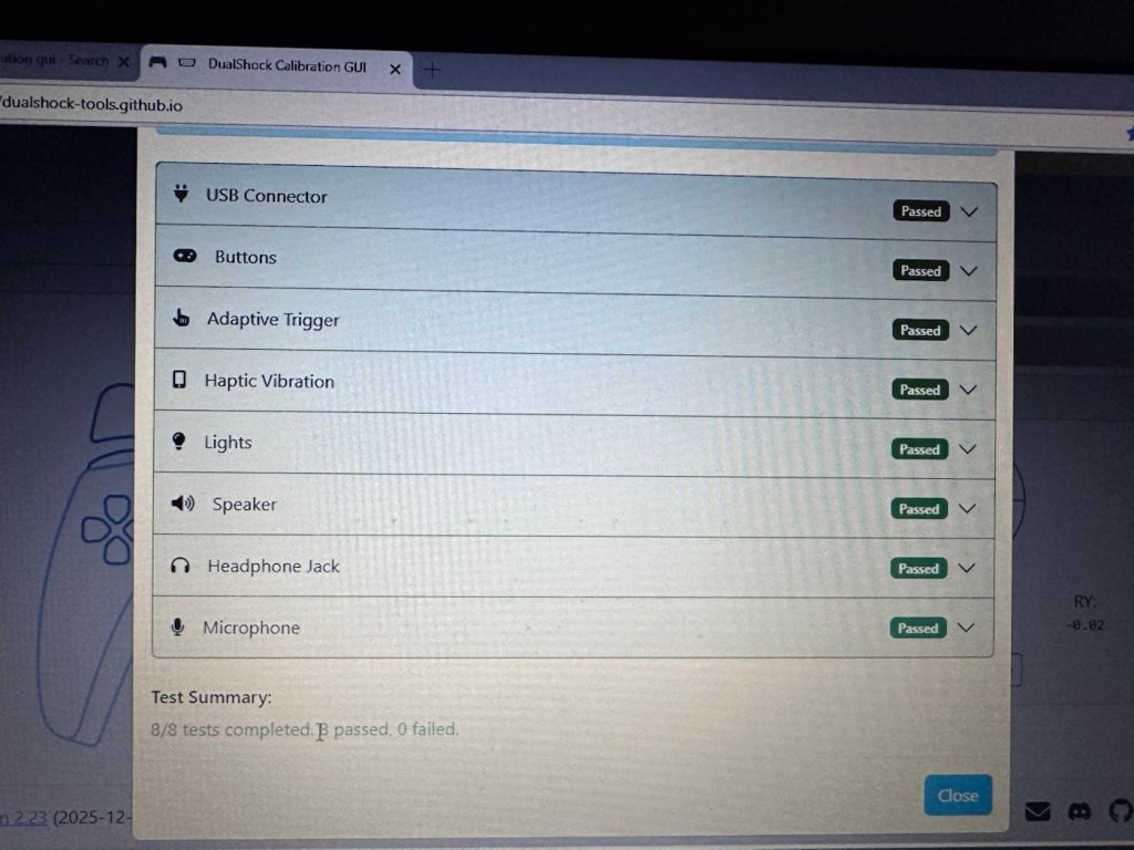
The checks are thus:
- USB controller: here the connection is tested a simple pass or fail
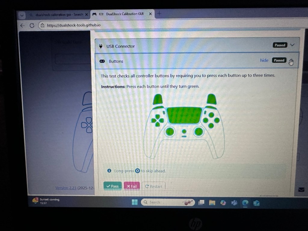
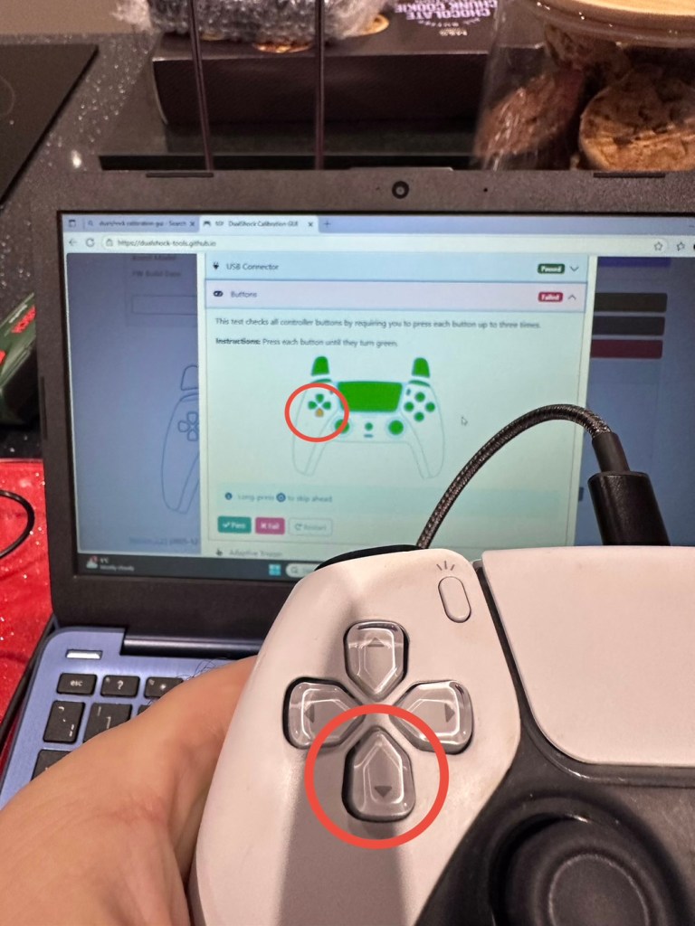
- Buttons: all buttons have to be continually pressed until they turn green on the screen, a simple pass or fail
- Adaptive trigger: the system puts a resistance on the two triggers representing various triggers on guns and switches experienced in various games, if there is suitable resistance here the result is a pass.
- Haptic Vibration: this tests the vibration motors in the controller, if it’s working then it’s a pass
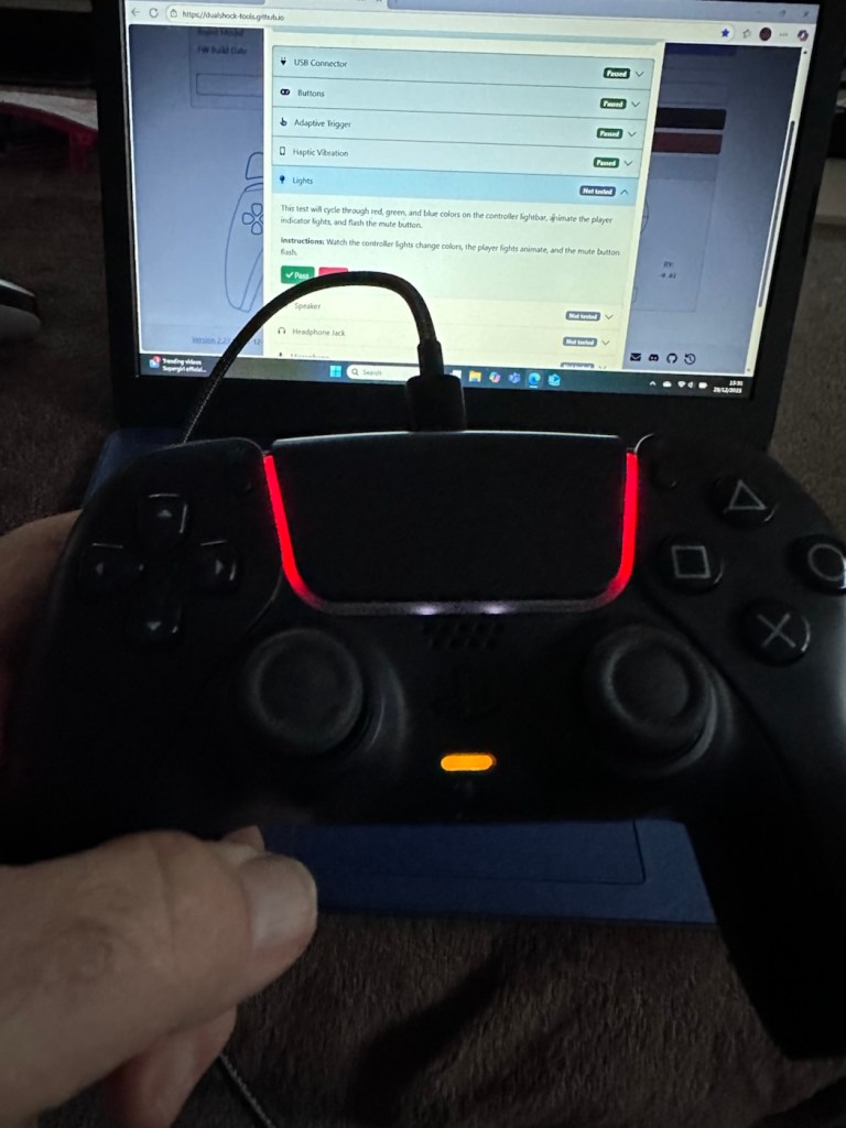
- Lights: all lights on the controller are cycled through displaying the whole range. Simple pass or fail
- Speaker: a tone is played through the built in speaker, a simple pass or fail.
- Headphone jack: a simple test of the plugin headphone jack – pass or fail
- Microphone: a simple test by blowing in the on board microphone checks if it’s working, a simple pass or fail.
And as stated the first controller, the black one has passed all of these tests. Impressive. The next tests are all centred around the two thumb pads, their return to centre position and their all around circular motion and their calibration.
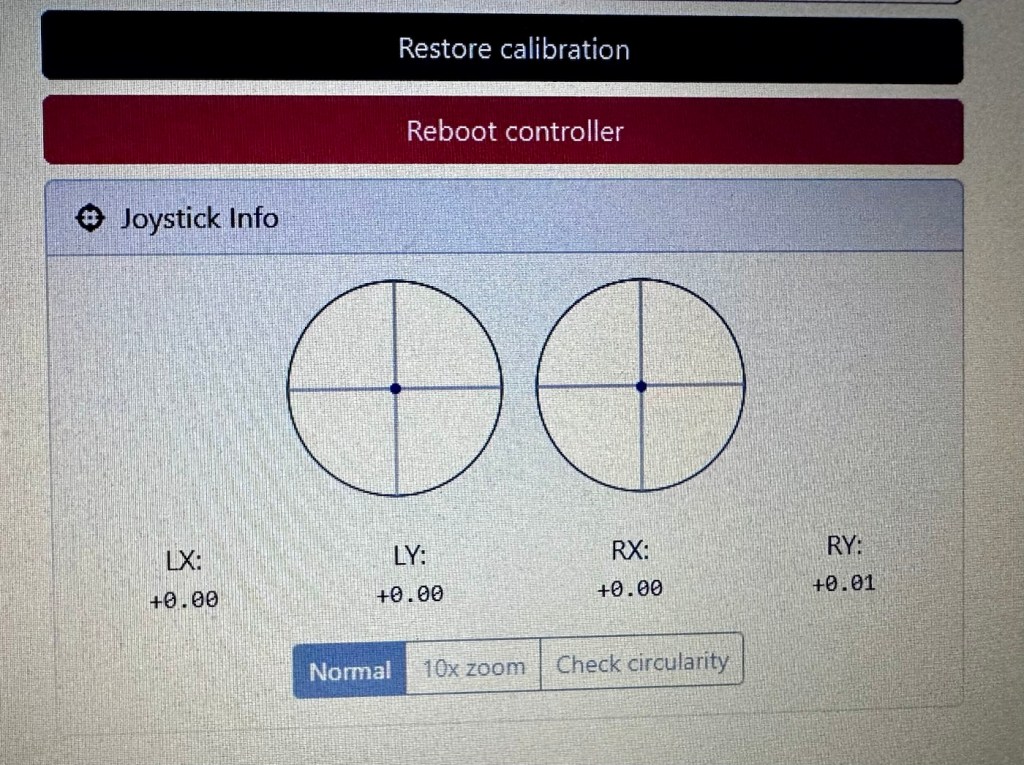
The left pad was showing slightly off centre and I was able to make some minor adjustments via the program interface to correct this issue. The good news was that it is not a constant stick drift, and the mechanism does not require replacement, it is easily adjusted. With settings saved, disconnect the controller, reinstall it and re check the calibration and it should all be good. And it was. With minor adjustments made to this controller I am pleased to say it is working as it should, it is now repaired and will be heading back to its owner.
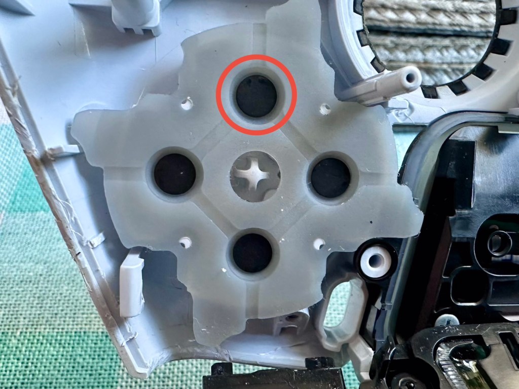
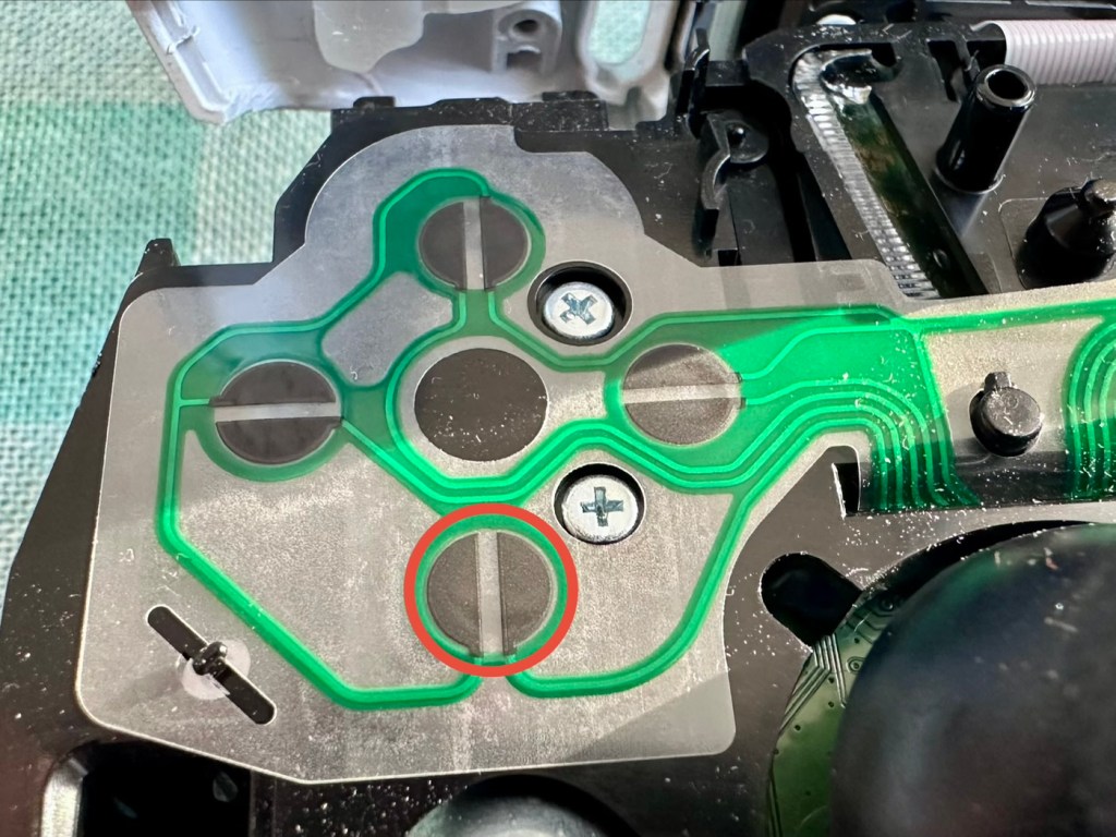
Now onto the second item, the white controller. I put this controller through the exact same testing protocol as the first one, all was going well until we got to the buttons section where this one failed. The down button on the left hand side of the controller is unresponsive, you can see this in the photos below
All other tests on this controller were fine. Again there was a little drift on the sticks that I was able to adjust and they are now both as central as they can be, operating well through their whole range. I will go through the repair and retesting of this pad in the section below the YouTube video that I have highlighted below.
A while ago, if your game pad was playing up, there wasn’t really a great deal you could do apart from replace the thumb controllers if you were experiencing issues such as a little stick drift (when a controller is moving on its own accord). A bad case of stick drift would require you to change the controller mechanism. However, some very intelligent people within the gaming community have put together a number of packages to test your game controllers, but the one mentioned in the video below has been a game changer as such, as it also allows adjustments to be made and saved and thus extending the life span of the components within, thus reducing the need to replace and dispose of those components prematurely. Have a look, it explains the testing protocols and checks them against other programs.
Repair and retest
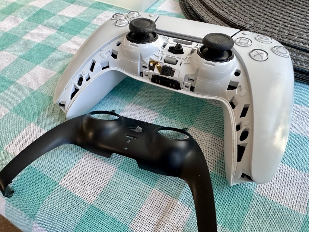
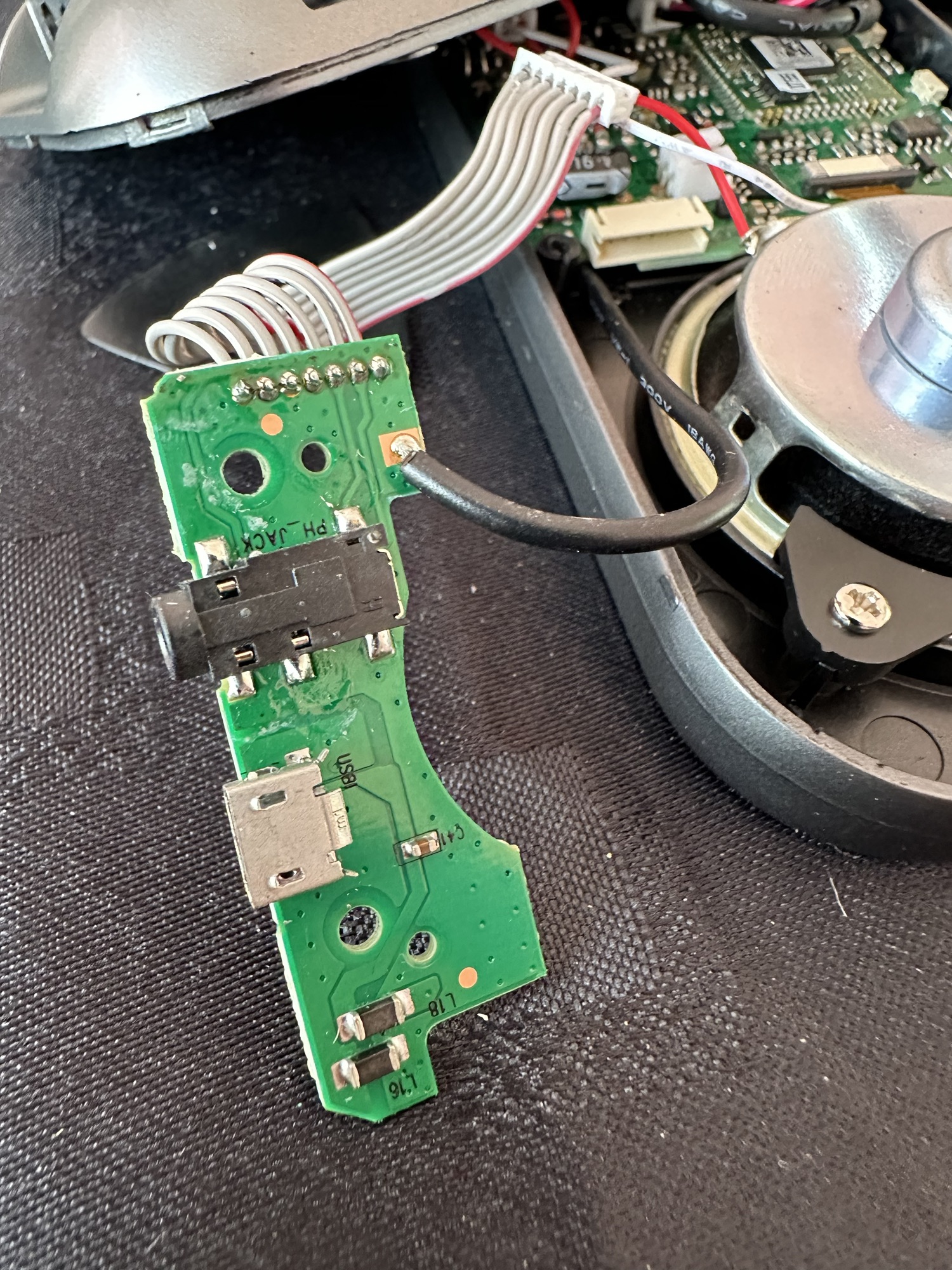
It’s a simple enough activity to get inside of the controller, some clips, and four screws get you inside the package, getting beyond this though to the controller buttons where we need to be is a little bit more in depth. So here we go…
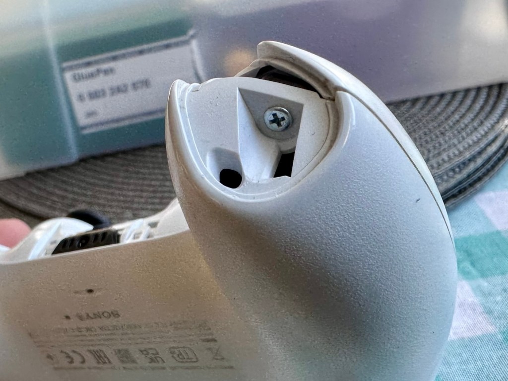
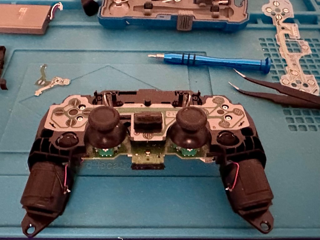
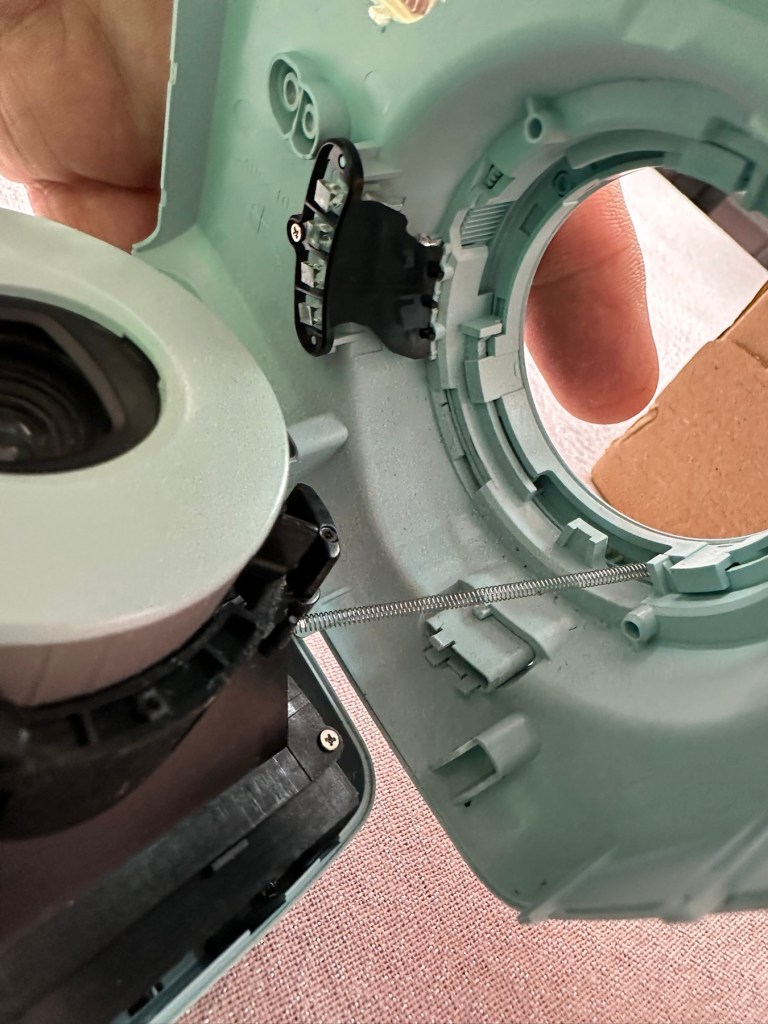
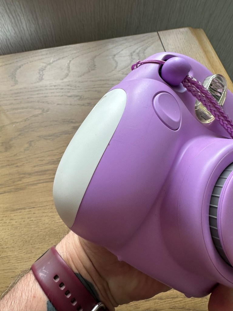
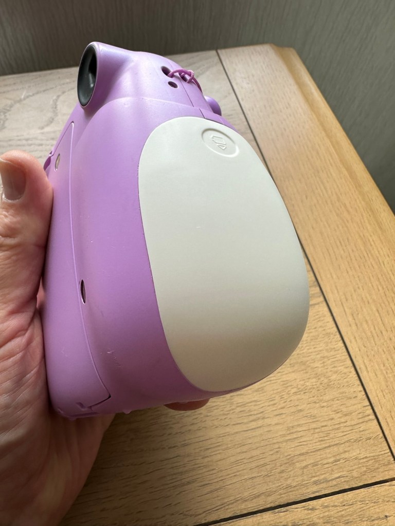
I’ve dismantled the controller as I said I would, initially the process requires four screws removing, after you first gently prise off the black decorative plastic surround as in the pictures below.
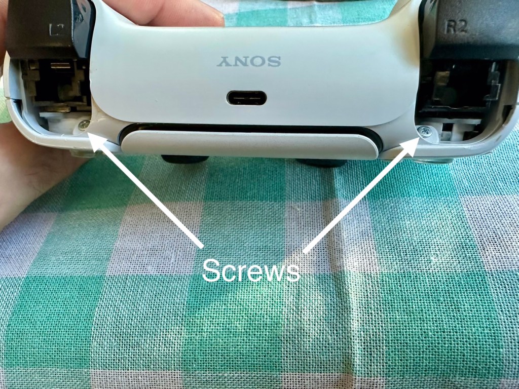
When you remove these screws the next task is to gently prise the two shells apart that then reveal the base of the controller
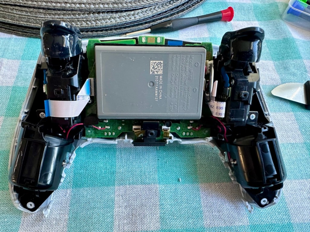
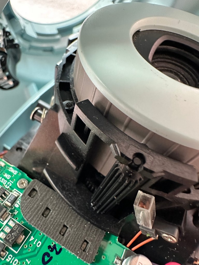
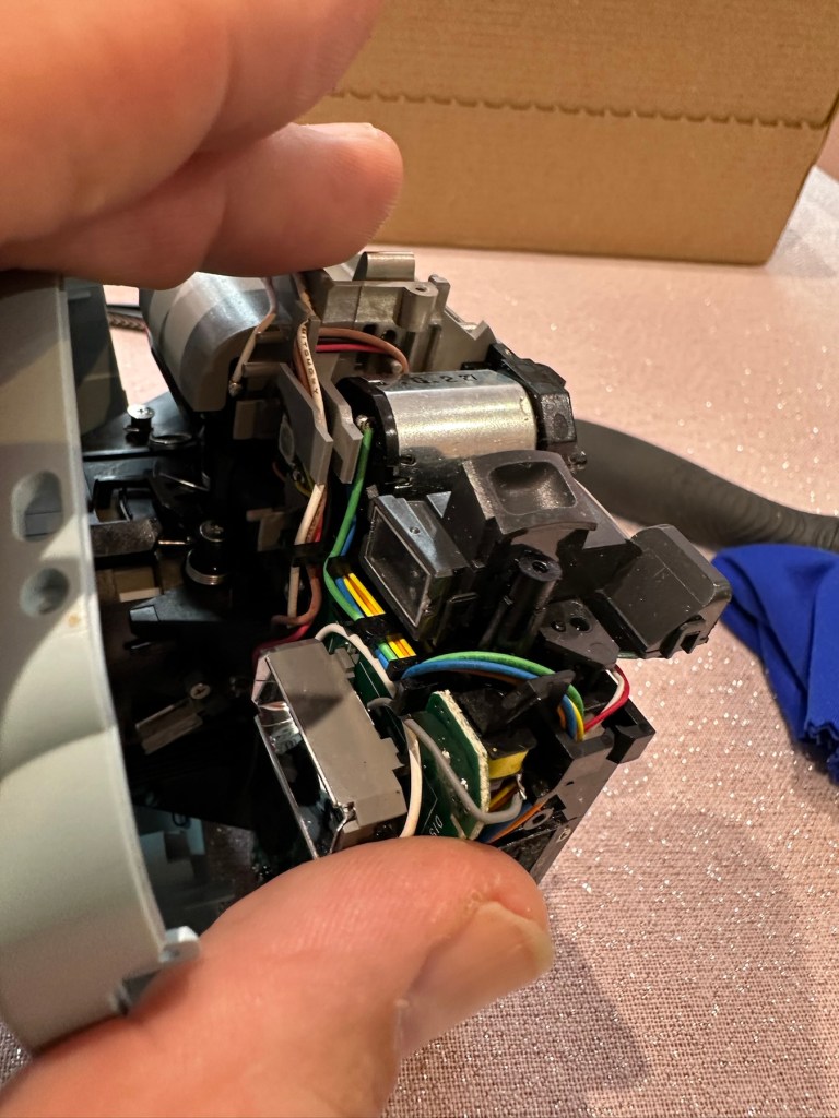
At this point the battery needs to be removed and that is a simple plug disconnection, the battery plate has a single screw in it that needs removing. Before you remove the battery plate there are four ribbon cables that need removing, if you don’t do these then you will probably tear them and need to replace them. Believe me, I have done this in the past and ruined the tiny microphone ribbon at the very front. It’s not expensive to repair, just an unnecessary expense. Don’t rush it. Another 3 screws removed and we can now take off the top cover and get to where we need to be.
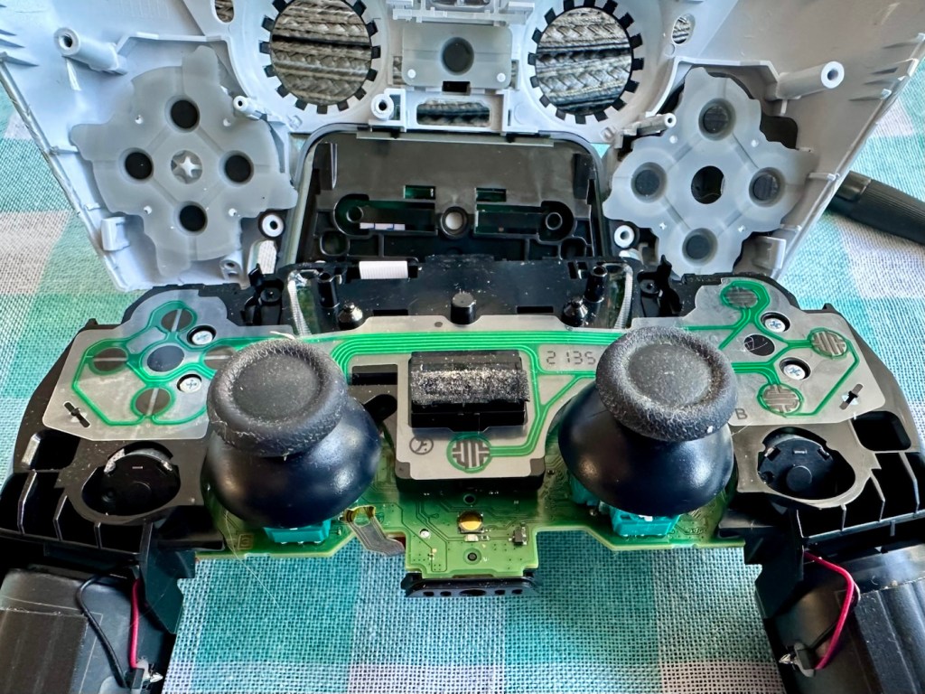
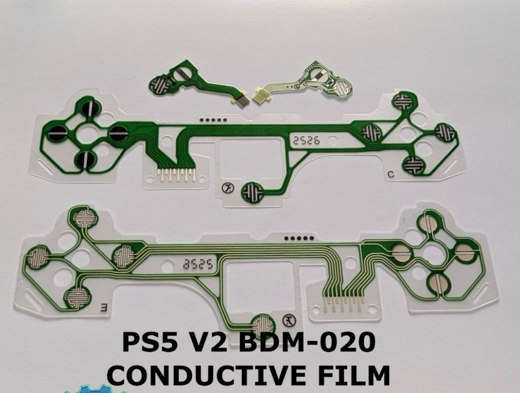
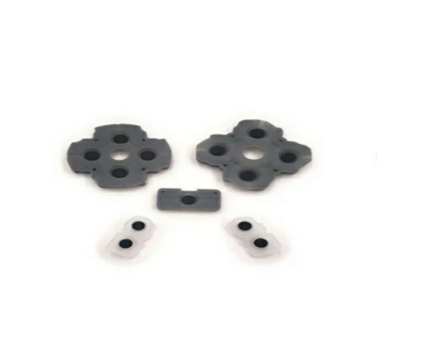
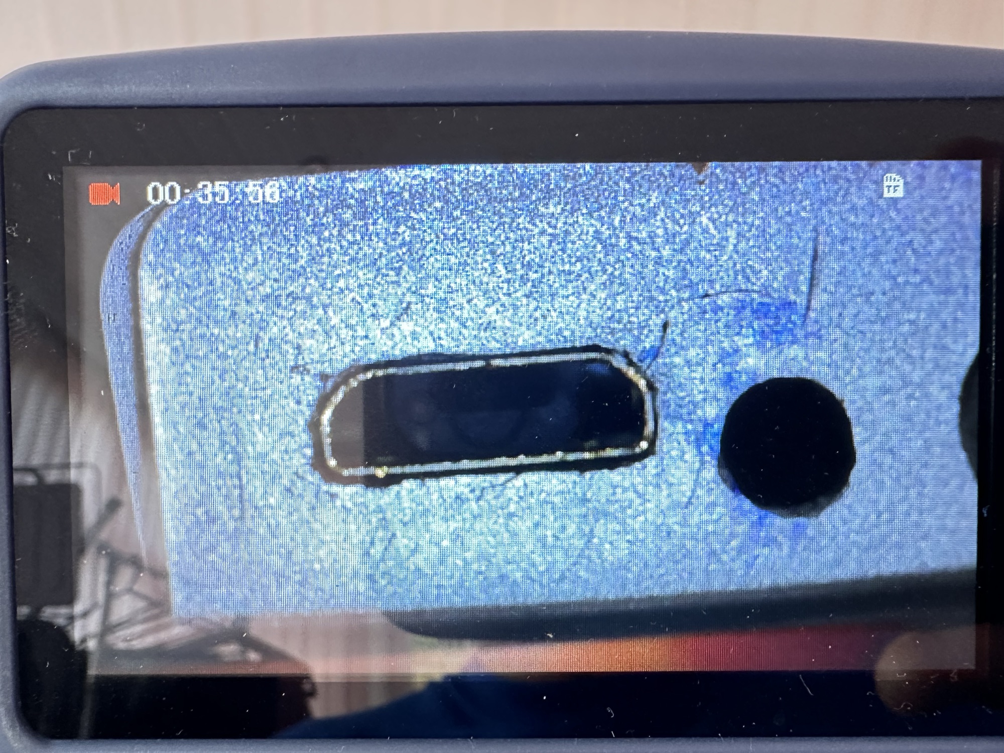
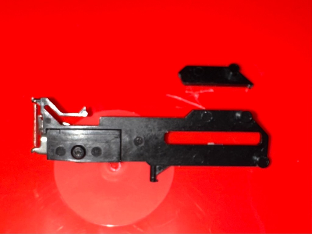
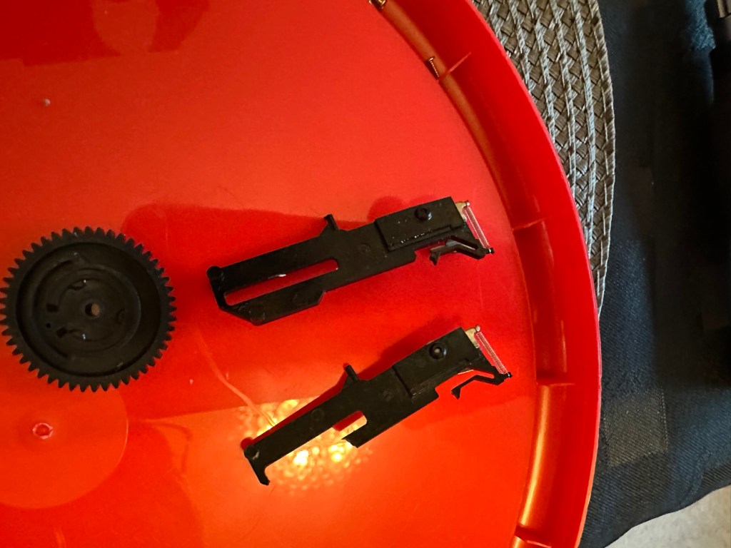
As soon as the top was removed I could see the potential issue with the controller direction pads. The pads are a rubber base with a carbon pad that makes contact with the circuit board below. Sometimes a simple clean of these pads can be sufficient to regain a connection between the two, but in this case it was plain to see that the pads on both sides were both well worn and to be honest they both required replacement.
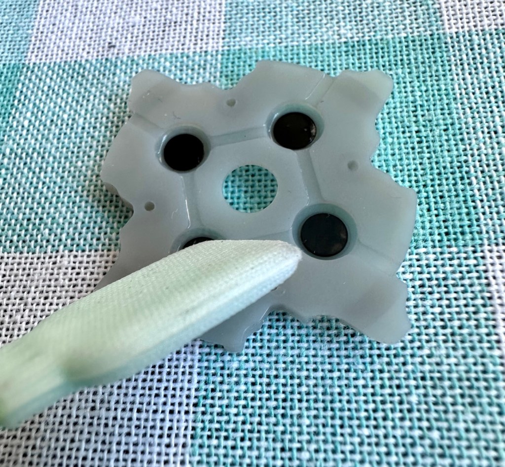
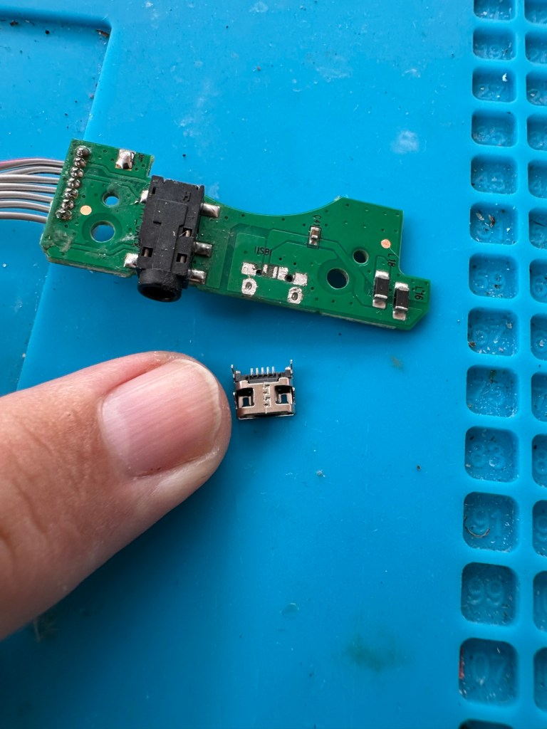
As stated I did give a clean to all contact points with a solution of IPA, reassembled and tested again with no change in performance, the fault remained. I will now need to purchase a new pad assembly and replace the film circuit board below them. Fortunately these are freely available and will cost no more than £6:60GBP to replace. And considering a new controller would cost at least £60:00GBP it’s worth the small investment to restore it.
I now just have to wait to receive these items and get them installed.
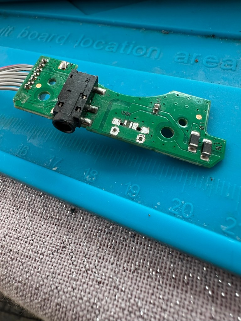
The items arrived just as in the photos above, and following the previous instructions to dismantle the unit, I have removed the old conductive film sheet and replaced this with the new one. I have also removed the silicone pads with the carbon inserts and these have also been replaced.
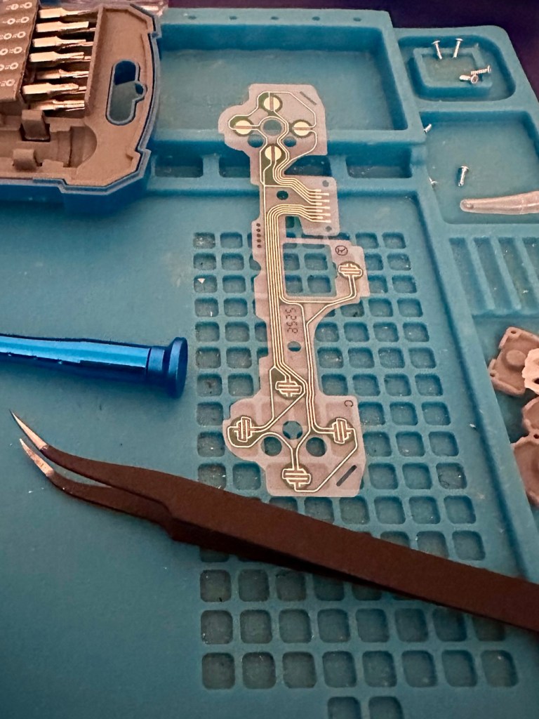
Now all I have to do once I have connected the ribbon cables is to get the outer shell back on the controller. Once this is done, I can log in and start the testing process once again, connect the controller to it and then commence a full test of its functionality.
And as you can see in the above photographs, this has been a successful outcome. Where the left hand side lower button had failed, the new conductive film has addressed the issue and this handset now has full functionality and is working as it should be.
Next I’m just going to do a re-calibration, to check that the sticks haven’t drifted in anyway. If we are in a good position, we can then class this repair as successful and then it can then be passed back to my nephew to carry on shooting aliens, and he can then continue his mission to save the world.
Result:
Two controllers have now been serviced and are both working well and within tolerance. They are about to be returned their owner so he can get them back into use, killing aliens and saving the world from a zombie apocalypse (or whatever he does with them)
Not having a lot of experience prior to receiving these two controllers, I was a little doubtful about where to start and what to check. However after reading up on them, and their operation, I was able to pick up a lot of advice and information regarding their manufacture and serviceability. I like to think that I’m well clued up on these items now as I can disassemble one in minutes, replace parts and reassemble without having any screws or parts left over ( Always a good sign 👍)
And to round things off I have now been given one of his friends controllers to repair as well, so I must be doing something right!
Thanks for passing by, as always it’s always very much appreciated.


You must be logged in to post a comment.