A compact Canon 35mm camera from 1982. It doesn’t work, so let’s make it work!
What the listing stated:
In generally good condition but does not power up Sold as spares or repair
EBay
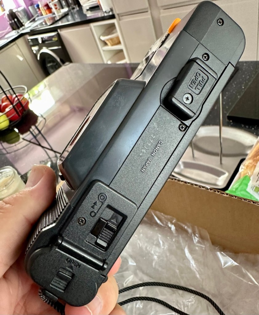
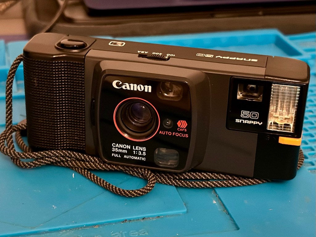
Canon snappy 50
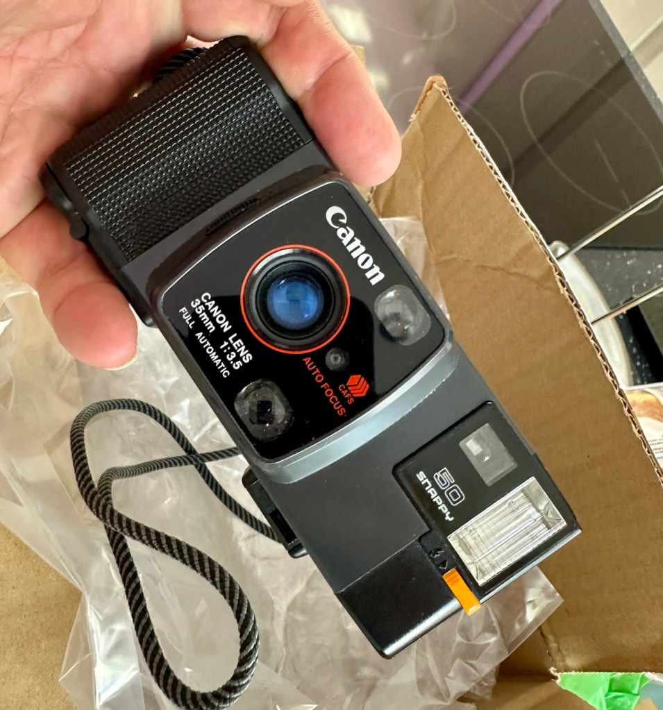
I came across one of these a few weeks back and was just taken by the shape and aesthetics of it. However i wasn’t going to pay a high price demanded by the seller, so i just hung around and waited for others to come on the market. I have just purchased this camera with free postage for a total of £1:13GBP. I’m confused, the seller will basically be paying me to take it off his hands as postage will be at least twice the value of what I have paid today. Let’s wait and see if this sale gets suddenly cancelled, as I suspect it may well do.
Anyway here’s a little bit of its history:
Released in July 1982 and based on a new concept, this is a fully automatic 35mm Lens-Shutter compact camera.
The camera height was reduced by about 30 percent, giving the camera an oblong and unique form.
The camera uses active autofocus with a solid-state near-infrared beam. EE and the aperture are controlled electronically with a program. Metering range is EV 8.6 (f/3.5 at 1/30 sec.) to EV 15 (f/9.5 at 1/350 sec.). The shutter speed is set within a range of 1/20 sec. to 1/500 sec. to suit the film speed.
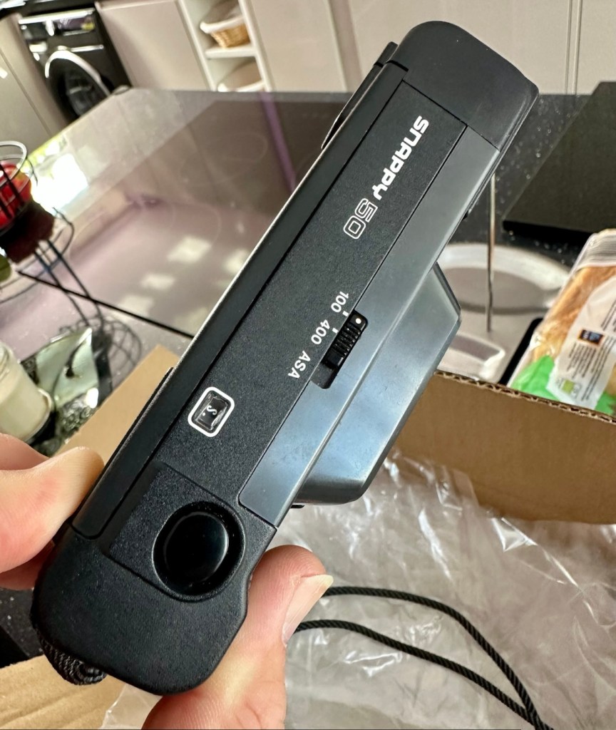
There is only two film speed settings. ISO/ASA of 100 or 400.
The built-in flash (Guide No. 11 at ISO 100 in m) must be turned on manually with a switch when the camera-shake warning lamp lights in the viewfinder.
Canon
I’ll just wait now to see if it turns up. I don’t know what the problem with it is, it’s just listed as a power up problem.
Well I’m shocked, I’ve received a postage notification so it is definitely on its way. Next stop…Assessment.
Assessment:
Well, it arrived, I’m shocked. It’s got to be one of the best packaged items I’ve ever received, never have I seen so much bubble wrap protecting an item that cost just £1:13GBP.
My Canon snappy 50
On top of that the sender has spent £3:45GBP on postage and charged me nothing. God I feel guilty now, least I can do is give him some glowing feedback.
Wow – And I paid nothing
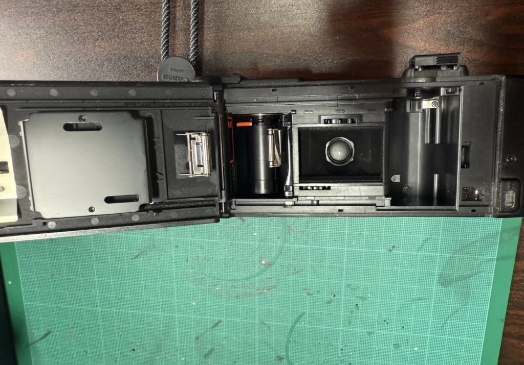
Right, back to the camera. For a 44 year old camera it really is in beautiful cosmetic condition and needs nothing but a slight dusting to finish it off. But first I put in two AA batteries and can confirm it is dead. No life at all. Also, the film door is flapping about (So there was another issue!). I’m going to have to get inside this unit to see what is wrong. To be honest the unit is such a basic one, I suspect there isn’t a lot that can go wrong with it.
Repair:
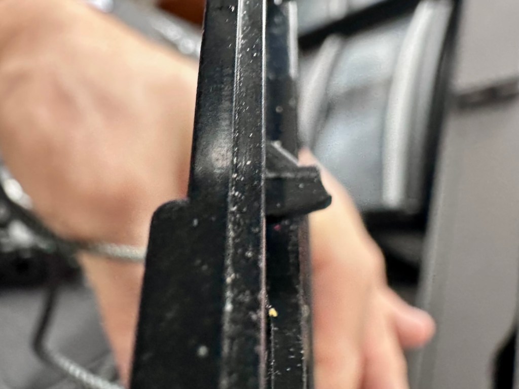
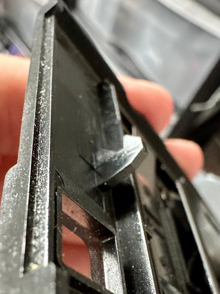
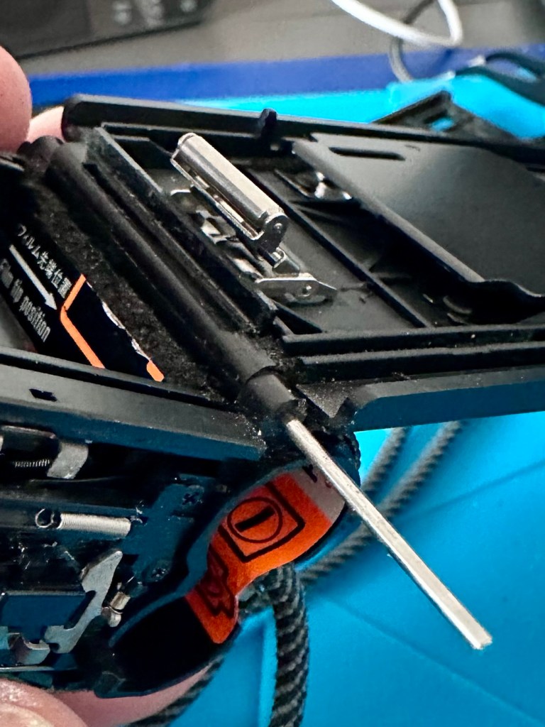
The film door issue is a simple one, and if I didn’t have a ton of spare parts spread around the place, I’d be quite annoyed to say the least. It would have been either a case of making a new catch for the door or building some Heath Robinson contraption to secure the door, looking completely out of place. However, I just so happen to have a complete rear door for one of these cameras so hopefully it should be a simple swap out of parts.
Broken door catchReplacement door with catch
But before I do this simple replacement, I need to get the top and bottom off of the camera to check where the electrical issues lie.
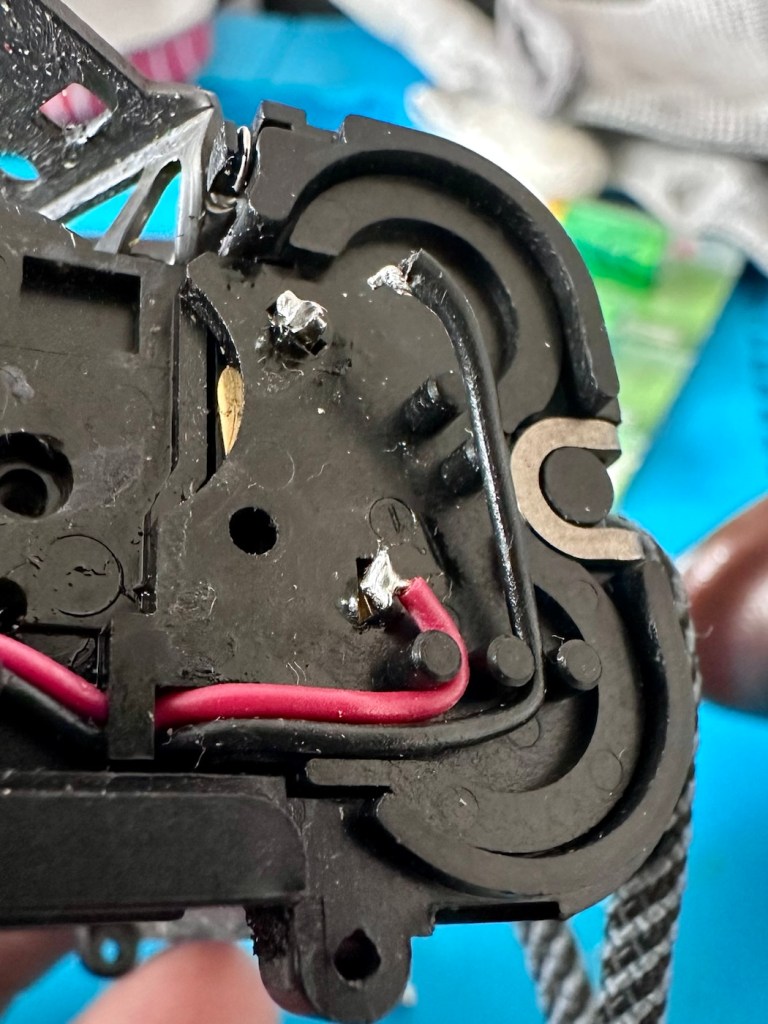
Taking the bottom off of the camera, the problem presents itself quite clearly. At the bottom of the battery chamber the negative wire has detached and needs soldering back into place.
Negative wore detached from battery chamber
I put the base back on and put two batteries into the chamber and the rewind motor instantly kicks in. We now have power. The shutter works and the winder motor operates as it should. When the rewind button is depressed the rewind motor kicks in as well, all seems to be good…..until!
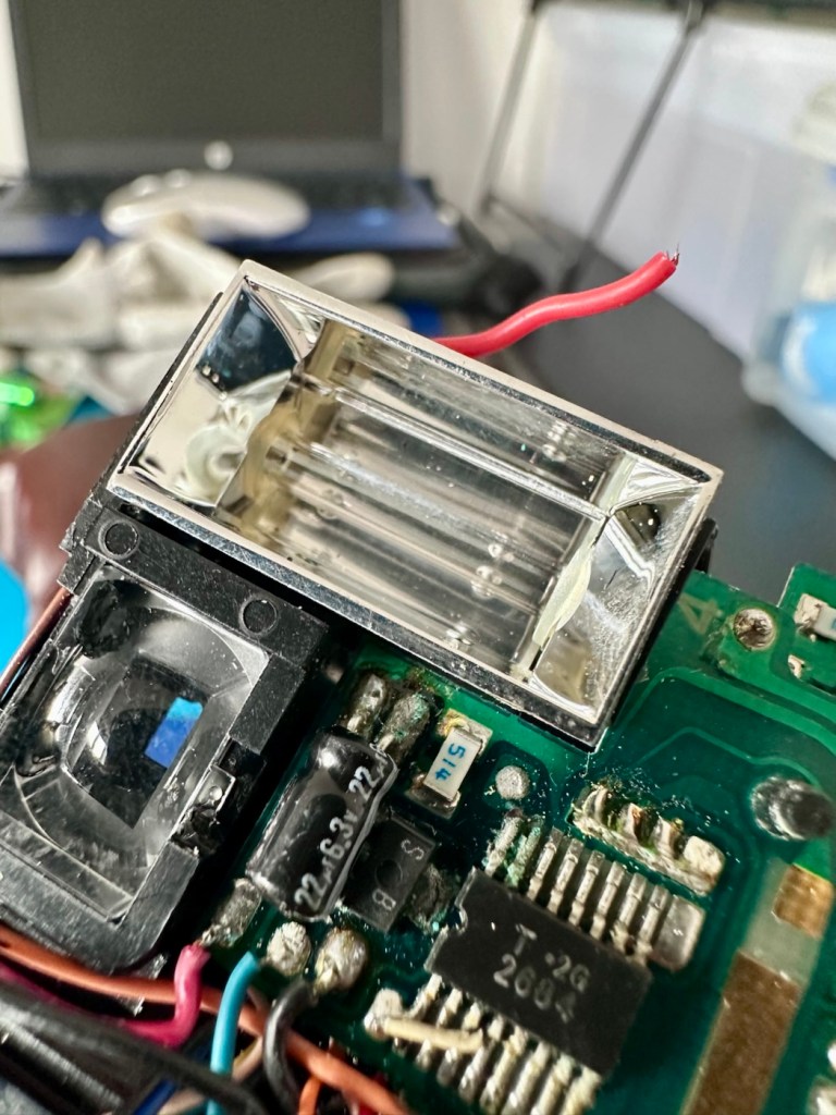
The live supply to the flash was detached
I try the flash, and nothing. Not even the usual sound of the flash capacitor charging. Damn, I hope that capacitor isn’t dead! So now I have the top off of the camera and another problem presents itself just as clearly as the first. Not a problem here as I need the top off to replace the rear door.
Rear door hinge removed and replaced
The live supply to the flash had broken loose and this also needed re soldering, in fact I re soldered about eight wires in total as it seemed that the solder joints in these critical areas could possibly be fairly. They may not be failing, but whilst I’m inside why not just do this simple task to prevent anymore premature failings?
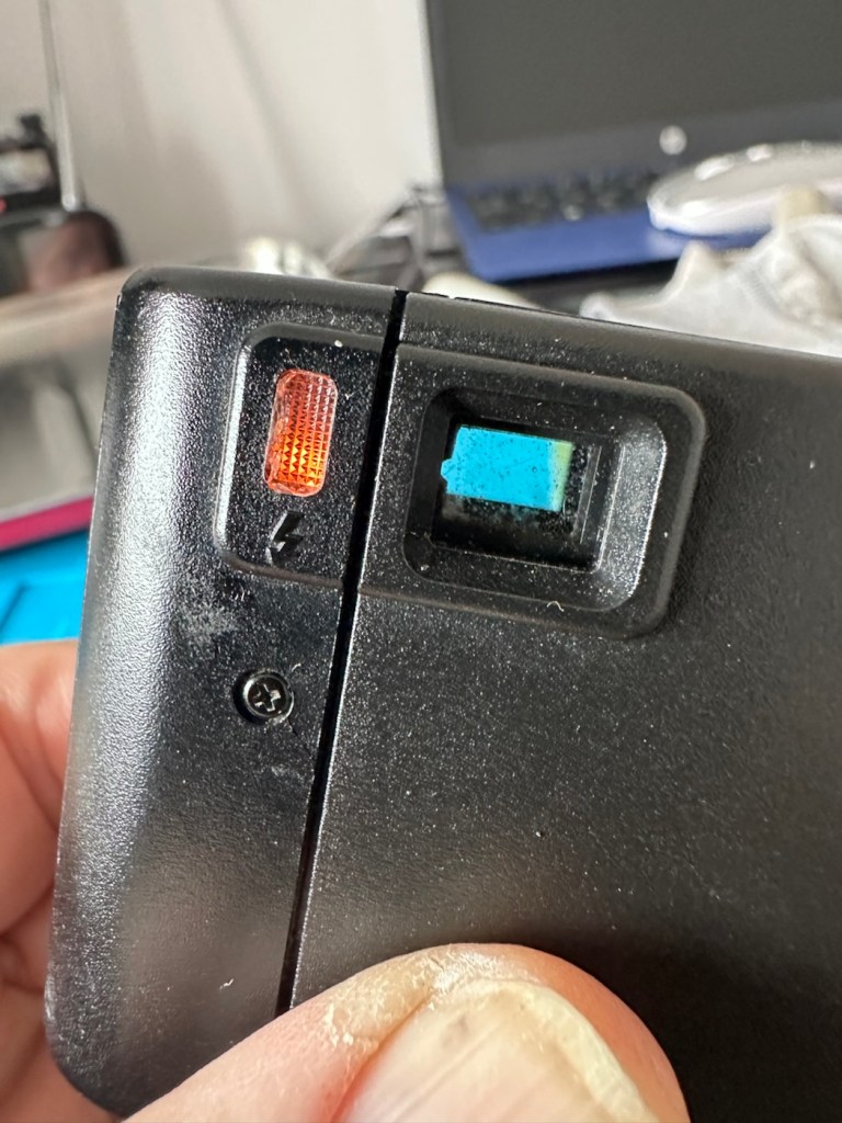
Batteries back in, flash turned on (it’s manual on this camera) and the check light illuminates. This camera is now fully operational.
Flash check light now illuminates
Result:
I’ve had a fairly simple repair here with some soldering and luckily, some spare parts available. These cameras are quite tricky to repair due to their compact build. Normally when you detach one part you have tiny springs and other parts that fly out, leaving you with a head scratching puzzle to add to your issues. However having dealt with these cameras in the past and having learned my lesson previously, I was very careful and took my time ensuring nothing occurred that would cause me any issues further along in this fix. I also open these cameras in a box, so if anything does fly out, it doesn’t fall onto a carpet disappearing into the pile, it just falls into the box, saving me the embarrassment of looking for a tiny piece of camera, that could be just about anywhere on the floor of that room. You learn from previous mistakes, I have, and i now have procedures in place to prevent such issues happening again.
All cleaned up and working
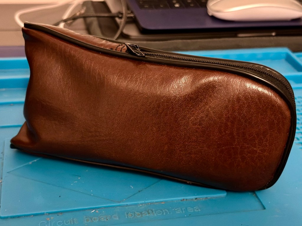
And neatly cased
We now have a lovely example of compact 35mm photography, rejuvenated, repaired and ready to get back to doing what it was designed for, creating memories.
And long may that last, another one saved from landfill, repaired, recycled and now with many more years of purpose.
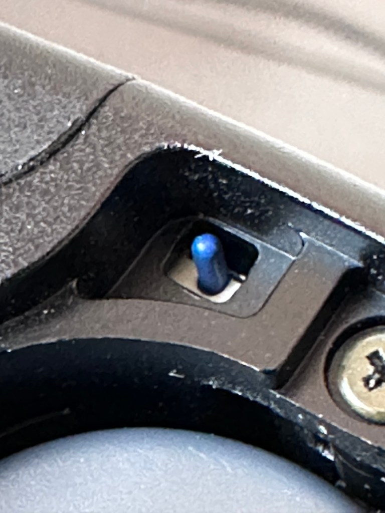
Who would have thought a button the size of a grain of rice could declare this camera defunct and dead. Let’s have a look at it and see if we can get it working again.
What the listing stated:
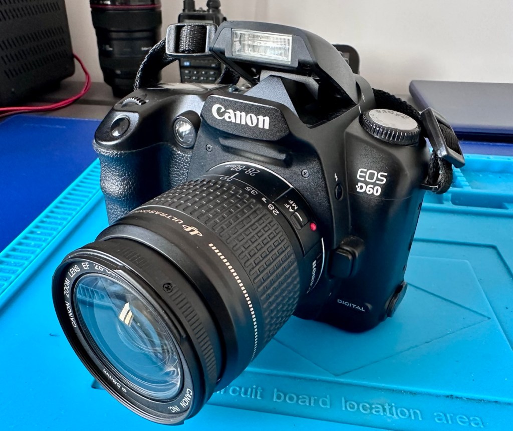
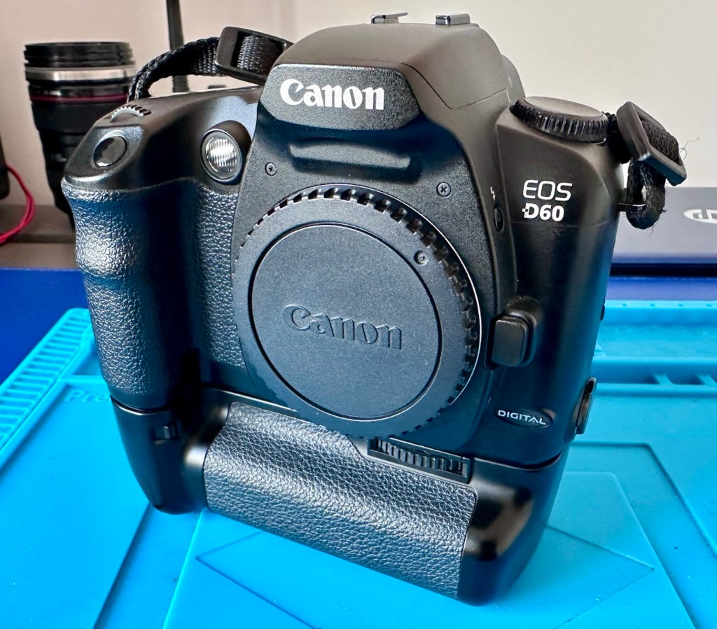
The Canon EOS D60 DSLR is a digital SLR camera body offered here for parts or repair, ideal for those seeking components or a restoration project.
This digital camera has been tested and does not power on. It is being sold as faulty, for parts or repair only.
Cosmetically, the camera body and battery grip show typical signs of use, such as surface marks and wear. Functionality has not been restored, and no further testing has been performed beyond confirming it does not power up. The battery grip (BG-ED3) is included but requires two batteries for operation; only one battery is supplied. No charger, lens, or additional accessories are included.
Accessories Included: BG-ED3 battery grip, 1x battery (no charger).
EBay
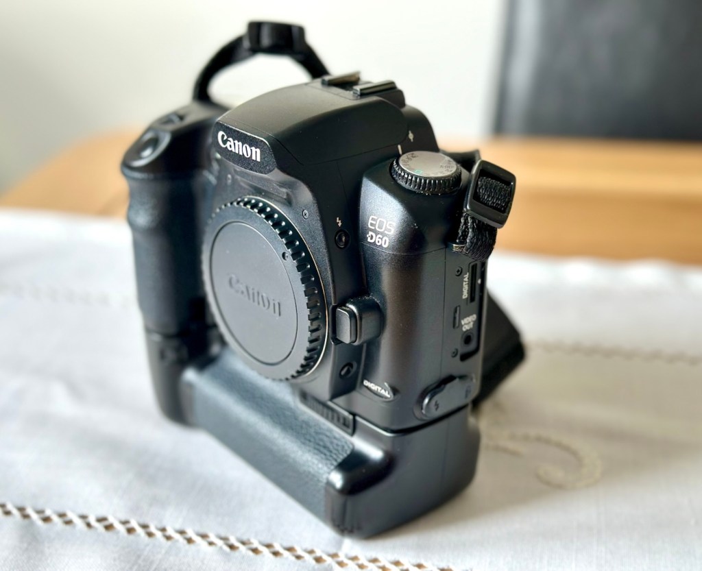
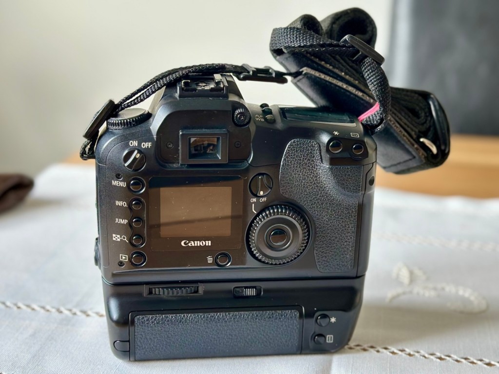
My Canon D60
I’ve purchased this camera kit for the princely sum of £14:24GBP. An absolute bargain, even if it doesn’t work. It’s worth more than that to me, even for spare parts if I can’t get it working, however let’s not go down that route just yet. This camera also comes with a BG-ED3 battery grip that on its own currently retails on the auction platforms for around £20-£30 so before we start I’m on to a winner.
Here’s a little bit about this camera that was released in 2002, don’t get it mixed up with the later EOS 60D that was released in 2010…a different camera entirely:
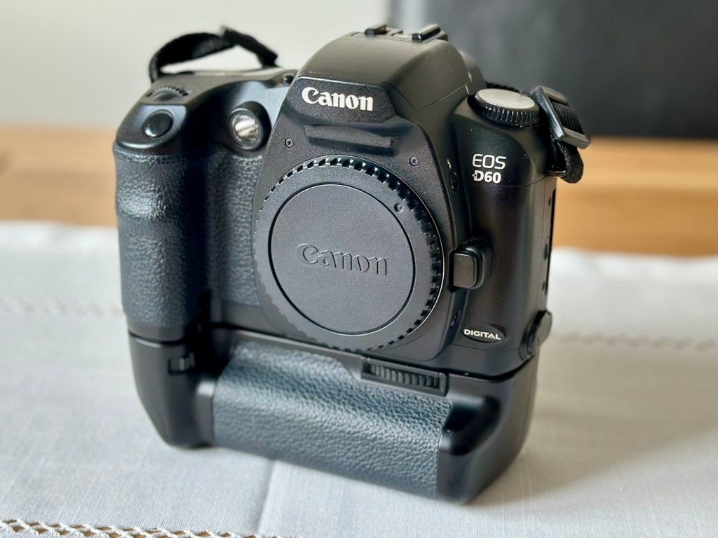
The Canon EOS D60 is a discontinued 6.3 megapixel digital single lens reflex (DSLR) camera body, announced by Canon on February 22, 2002. It is part of the Canon EOS range, and accepts Canon EF, TS-E and MP-E lenses, but not Canon’s later digital-only EF-S lens range.
The EOS D60 sits in the prosumer (professional-consumer) line of digital SLR cameras. It succeeded the three megapixel EOS D30 and was replaced by the improved, six megapixel EOS 10D.
The EOS D60 features:
22.7 x 15.1 mm CMOS sensor (APS-C)
6.3 megapixel effective (6.3 megapixel total)
Max resolution 3072 x 2048
FOV crop (1.6x)
Canon EF lens mount (excludes EF-S)
3-point auto focus
100, 200, 400, 800, 1000 ISO speed equivalent
30 to 1/4000 s shutter speed and bulb
TTL 35 zone SPC metering: evaluative, center weighted, partial
Exposure compensation -2 EV to +2 EV in 1/3 EV or 1/2 EV steps
Auto White Balance (plus 5 positions & manual preset)
Eye-level pentaprism viewfinder
1.8 in (46 mm) color TFT liquid-crystal monitor
E-TTL flash mode
3 frames per second continuous shooting (max. 8 frames)
Dimensions (WxHxD): 150 x 107 x 75 mm (6.0 x 4.4 x 2.9 in)
Weight (body only): 780 gm
Wikipedia
So, as usual let’s await its arrival so we can carry out a full assessment of the camera and related equipment.
Assessment:
The package has arrived, and wow, this is a lot of camera for a very small price.
A lot of camera for little cost
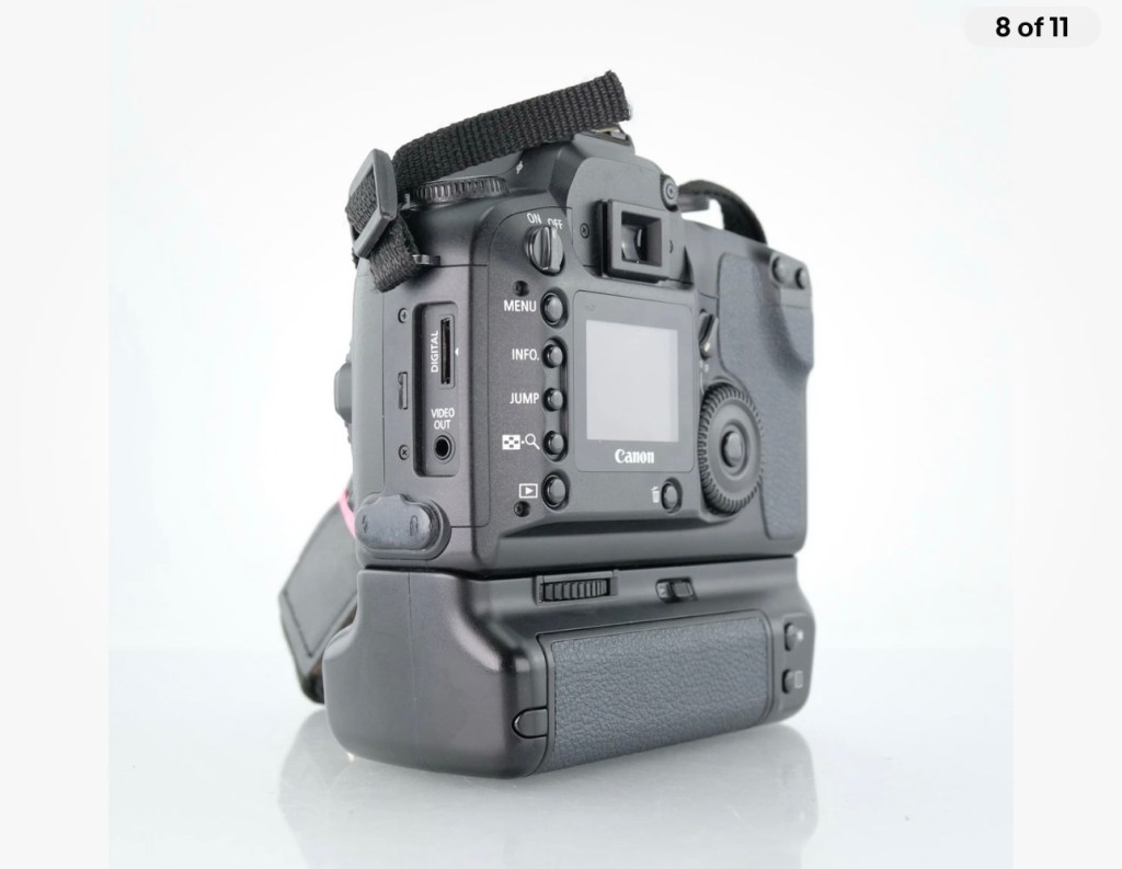
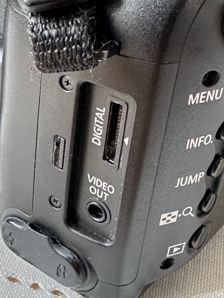
The condition cosmetically is fantastic, I’d call it almost mint but the seller thinks otherwise, he certainly has some high standards, I’m pleased I know him if it means I can purchase items such as this. The only thing that is missing is a small rubber cap that covers the digital and video out ports, not an issue for me, and definitely not detrimental to the operation of the camera, this can be replaced but it really isn’t worth the bother or the extra expense.
The missing rubber port cover
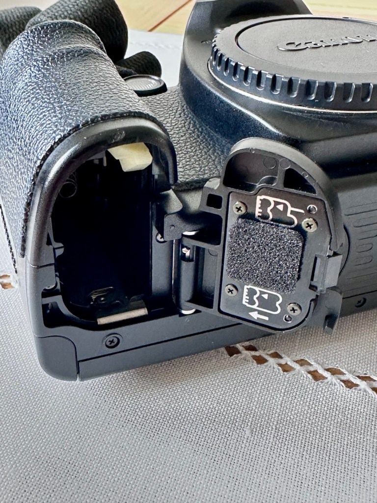
The camera has come attached to the power winder and has a Canon dust cap over the lens mount/body aperture. There is a single battery and this does have some life still in it.
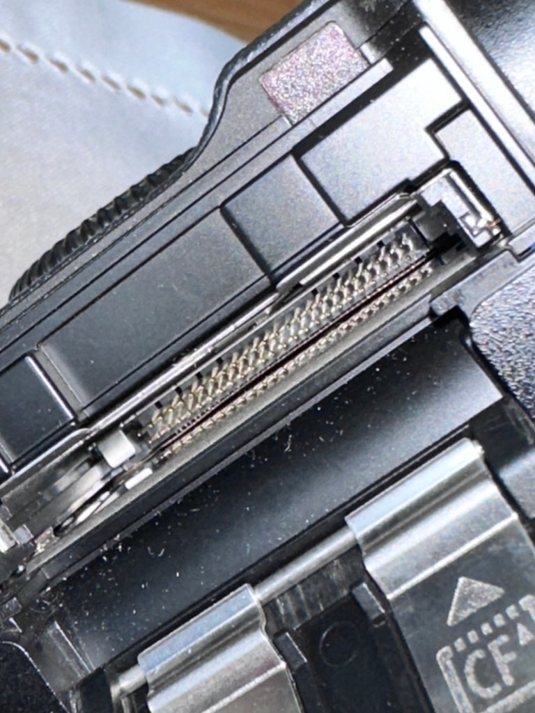
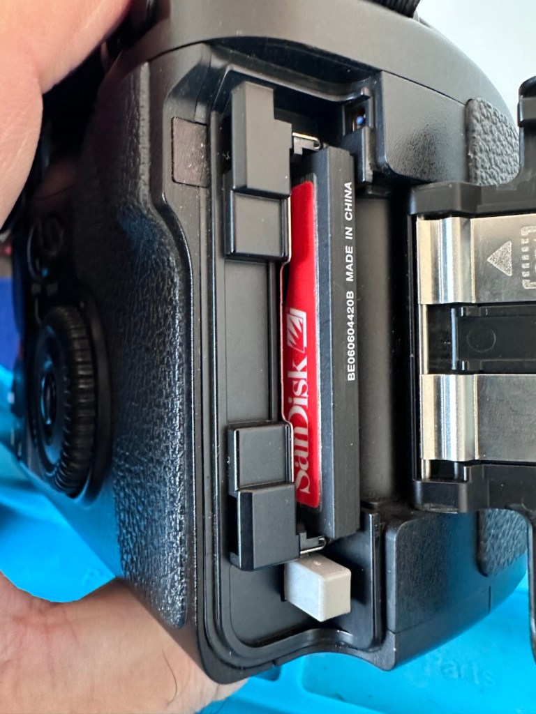
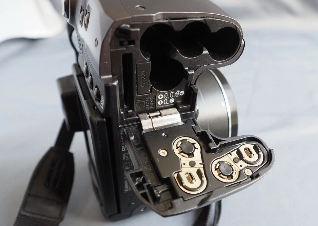
No damage to the CF card reader pins
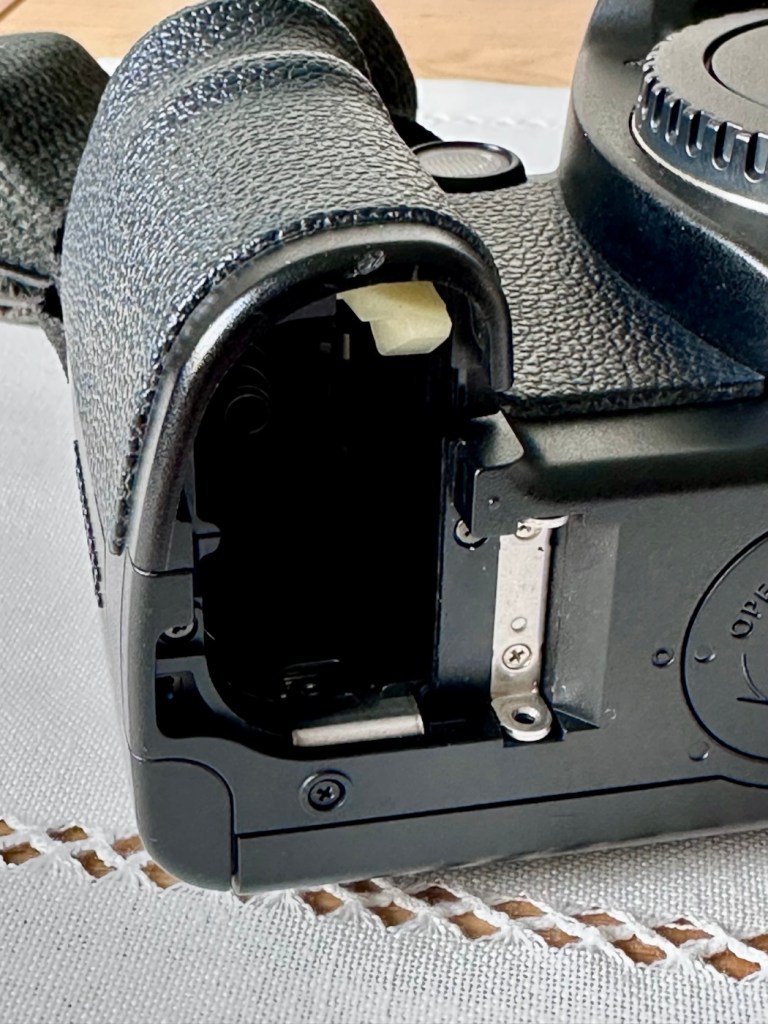
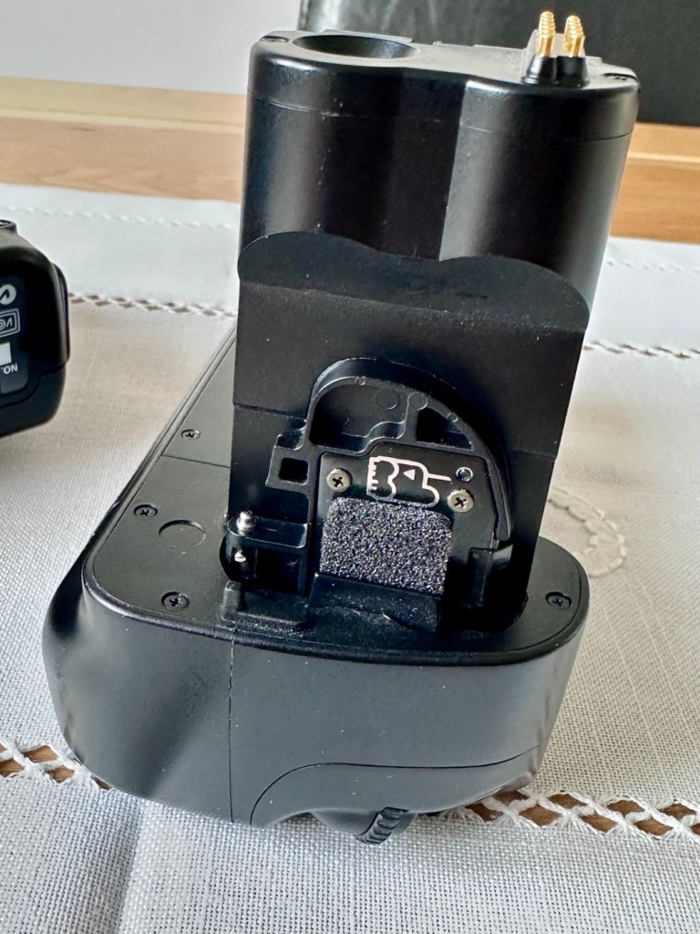
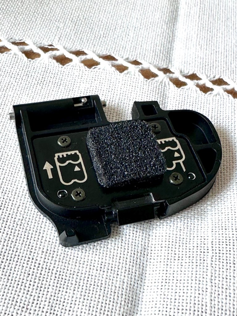
There is a good quality camera strap attached, and when the battery grip is taken from the body and checked, all battery connections are clean and free of any contaminants. There is no damage to the CF card reader pins within the CF card port. An added bonus is that the body battery cover is tucked away on the power grip handle, and all connections are good, these little battery cover doors normally end up being thrown away so that you end up paying some pirate on the internet an absolute fortune to replace a battery cover door, that in theory is only worth a few pounds. Yes there are many robbing bandits out there! (That’s the polite, non sweary word version)
Battery chamber minus doorDoor storage on battery gripBattery doorDoor and chamber reunited
The camera listing stated that the camera grip needs two batteries for operation, this is not technically true as one battery will still operate the camera whilst using the grip. The option for two batteries just extends the usage of the camera, hence saving you the aggro of changing out batteries when you have a longer camera session planned.
And that one battery does have life in it as I stated earlier.
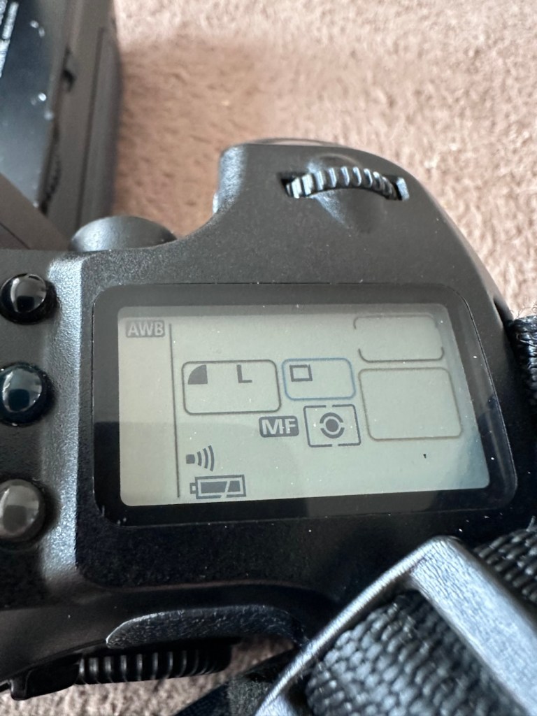
I know this, because I plugged it into the camera grip, I turned the operating switch on and hey presto, there is life
It’s alive!
So to further test I have removed the grip, and gone back to using the camera with its original battery cover, and then…it doesn’t operate. How strange!
So I then go back to the power grip and everything works fine!
Back to the original battery cover. Nothing again.
I won’t ruin your reading at this point, as to be totally honest if I tell you what was wrong here, I will have nothing to put in the repair section below. Just read on, I can assure you that you will not be impressed. It really is that mundane and boring, you will probably just roll your eyes and question why I have even called it a repair. But a repair is a repair, no matter how insignificant and minuscule it may be, and if it gets the camera working then we are on to a winner.
Repair:
Thanks for staying with me.
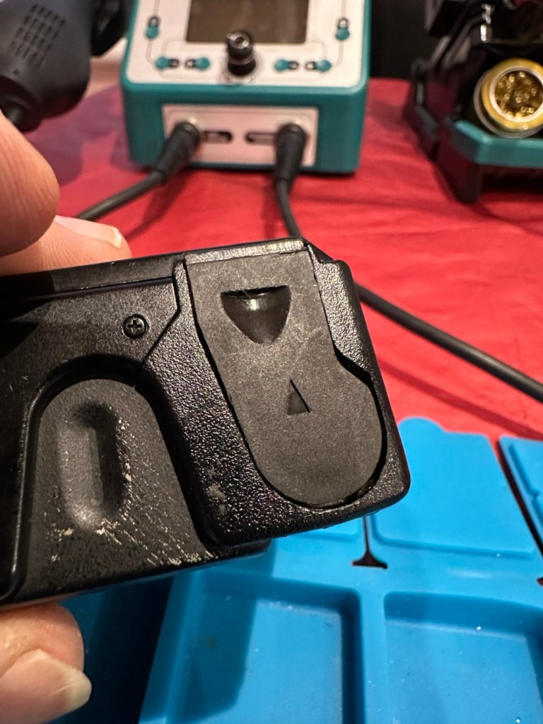
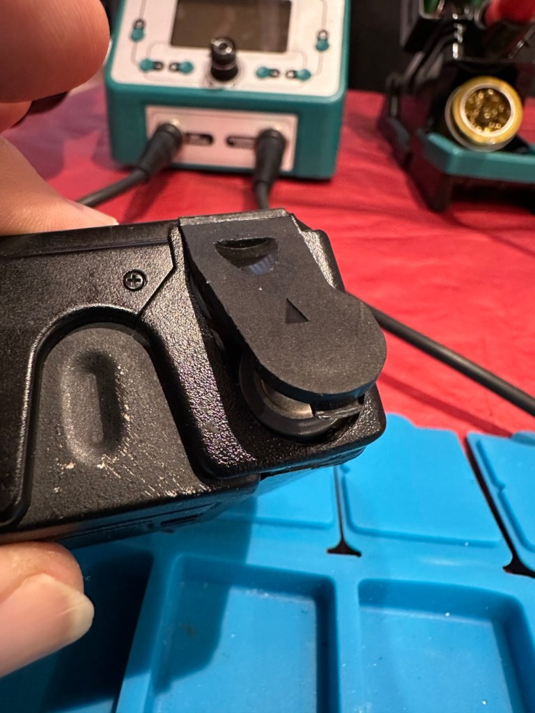
Have a look at the three pictures below.
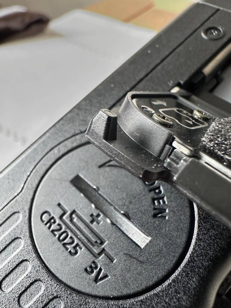
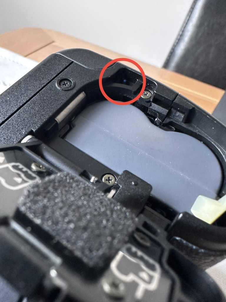
A lever on the battery cover….Activates a tiny blue button (Circled in red)That tiny blue button (enlarged photo)
The issue was with the tiniest of buttons. It wasn’t working.
A small tab on the inside of the battery door presses this button when you lock the door. If that tab is broken, or if the switch itself is damaged, the camera may act like the battery is dead or not installed.
The tiny blue button (or sometimes black/white) located inside the battery chamber of a Canon EOS camera is a safety micro-switch that detects whether the battery door is properly closed. It ensures the camera has a solid connection to the battery and that the door is closed to prevent damage. It acts as an instant cut-off switch to prevent data corruption (e.g., if the door opens while the camera is writing to the CF card).
If this switch is not engaged, the camera will not turn on.
And this appears to be the problem. The battery cover was not putting enough pressure upon the little blue switch, the switch also appeared to be a little stiff but soon loosened up when it was cleaned with some IPA and activated a number of times using plastic tweezers. It appears that when the grip was installed and fastened into place there was sufficient pressure to operate the switch, hence the issues I experienced when changing from one battery mode to the other, earlier in this post. Now, when either the original battery cover or the power grip is used, power continuity is restored, and the cameras screen and activities all appear to be working as they should be.
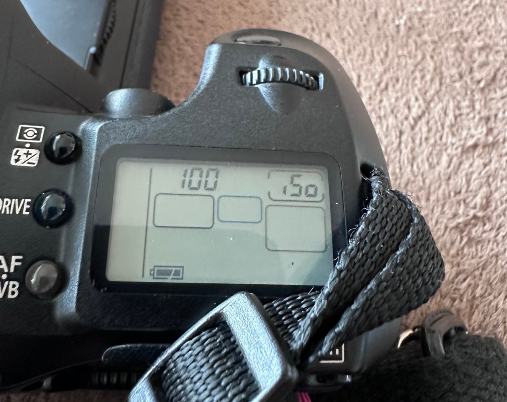
However, we need to now install fully charged batteries, a CF card, and need to get a compatible lens on the front to ensure all the dials, and buttons function and do as they should be doing. I know the flash is definitely working, as this popped up and fired when I was testing the battery earlier, I’m fairly confident we have located and dealt with the underlying issue, though it doesn’t hurt to do a full test of the system just to confirm our findings and to ensure that there is nothing else lingering around, just waiting to be found out.
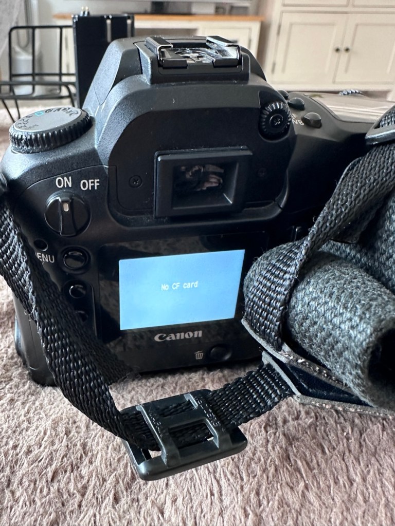
CF card and new battery installed
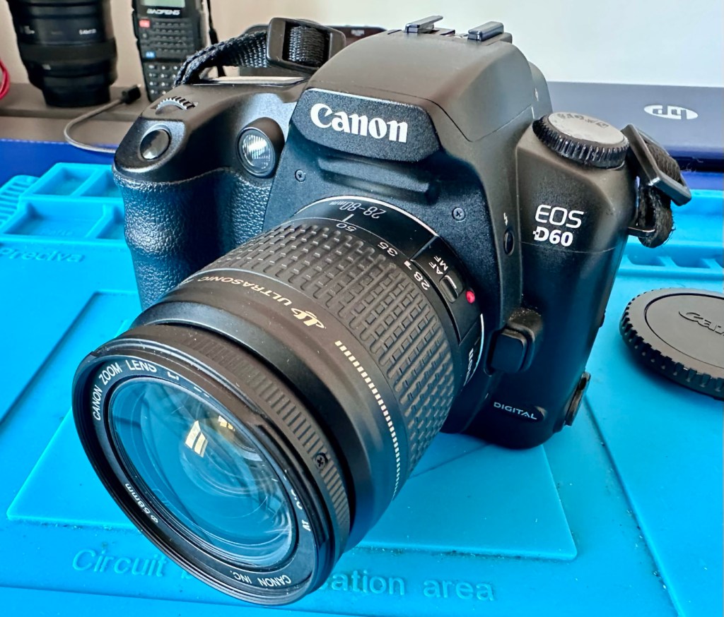
I’ve now installed a charged battery and a CF card into the camera, no issue here and all systems seem to be operating ok, no error codes or faults showing. I’ve put on one of my test lenses, a Canon EF 28-80 1:3.5 -5.6, and again everything is good, auto focus and manual focus, all works fine and all settings on the function dial are working just as they should. This camera is doing just what it should be. And appears to be working extremely well in all aspects of operation.
Result:
I’ve taken a few pictures in and around the house and everything appears to be working and functioning as expected. I can confidently state that this camera is working perfectly. It’s not the greatest of lenses as it’s just a test one I use for my cameras, but it proves the point though, that the unit is working and communicating well with all points of the camera.
Looking good and now in a working order
This is a fantastic camera, I only paid £14:24 for a lot of camera dating from 2002, less than the cost of a couple of pints of beer or three coffees, and from my point of view it is an absolute bargain. And it was all down to a little button comparative in size to a grain of rice.
Just a few random pics around the house to quickly test
So I am super pleased with how well this repair has gone, such a simple issue that totally killed the functionality of this unit, easily repaired, all it took was a good bit of investigation, probably taking no more than 20 minutes of my time. I must admit it helps to know a little about how these units function. It always amazes me though, that these sellers could make a bigger return on their items if only they had someone to give these units the once over before declaring them dead and fit for spares and repairs only.
However I’m not complaining as i get to add a superb item to my collection for a very reasonable price. Just browsing the sales sites shows that the basic version of this camera without the power grip is commanding a price of between £140-£150.00GBP, I only paid £14:24. I think I’m the winner here.
There are bargains to be struck out there, if you are willing to give a little time and patience into getting them back up and running. Recycling works.
Many thanks for passing by, it is always very much appreciated.
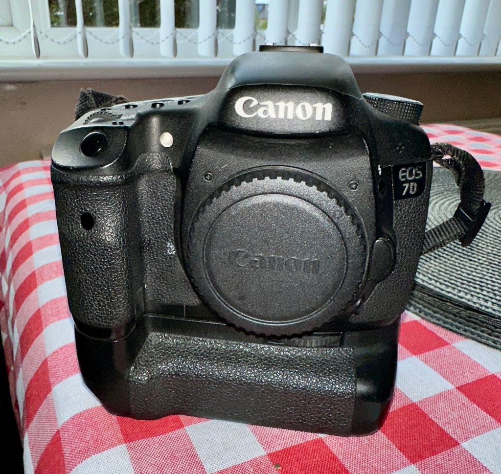
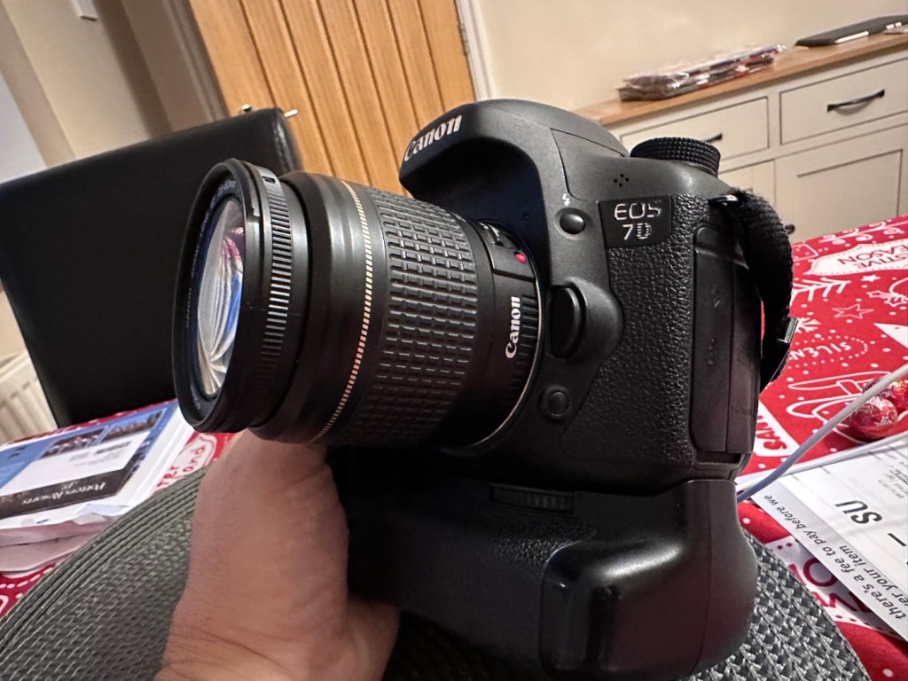
Can I get this classic EOS 7D operational again? It has damaged card reader pins.
I received this camera from a good friend who is a professional photographer, a few weeks back in a bundle of cameras and photographic equipment he no longer uses, he has kindly donated them to me to get working again. You can see that post, and just what was donated here: Cameras…i need more!
Canon EOS 7D
I’m in a situation where I don’t have my repair gear with me at the moment, as it is all packed and in storage awaiting our impending house move. Hence the reason I am racking up a whole load of draft posts that I can’t complete until I have my workspace back in use. Therefore any work I can do is severely restricted to inspection, cleaning and preparation with the only maintenance being attempted on the outside of the camera.
Let’s have a brief history on the Canon EOS 7D:
The Canon EOS 7D is a high-end APS-Cdigital single-lens reflex camera made by Canon. It was announced on 1 September 2009 with a suggested retail price of US$1,699, and was marketed as a semi-professional DSLR camera.
Among its features are an 18.0 effective megapixel CMOS sensor, Full HD video recording, its 8.0 frames per second continuous shooting, new viewfinder which offers 1.0X magnification and 100% coverage, 19-point auto-focus system, movie mode, and built-in Speedlite transmitter.
The EOS 7D remained in Canon’s single-digit APS-C model lineup without replacement for slightly more than five years—the longest product cycle for any EOS digital camera. Its successor was the Canon EOS 7D Mark II, announced on 15 September 2014.
Wikipedia
Structurally and cosmetically this is a beautiful camera in very good condition. However it would not have been donated to me unless it had problems. Let’s now put my detective hat on and go looking for clues.
Assessment:
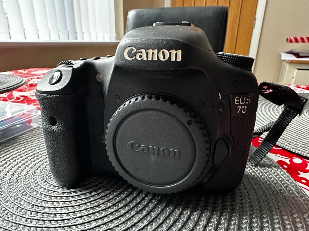
As stated earlier, cosmetically there is nothing at all wrong with this camera, it even has the plastic screen cover in place. Mirror looks clean and curtain looks fine no issues here. All electrical contacts such as HDMI are in good condition with no visible damage to the ports.
Everything is fine, cosmetically, externally.
One last place to check and I now believe this is where the problem lies. This is the CF card door, and when opened it reveals one possible big issue.
Bent pins
Bent pins on the CF card reader. These pins are quite small and only millimetres in diameter, in a very restricted space about 8 cms deep and 6cm in width, it really is quite a small aperture. There are two options here, one I try to gently coax these pins back into place with a fine point tool, however the pins are minuscule, and brittle and prone to breaking. I can see potentially 7 pins that are out of position, not an easy or expedient option. But I’ll have to give it a go. Option two is to purchase a new CF card reader replacement, this option carries some expense and quite a complex dismantling of the camera to achieve said replacement. Needless to say I will initially attempt the pin bending procedure. Pending on success or failure, i could venture into step two. Read on to see what occurs.
Repair:
With a fine point set of tweezers, I’ve decided to have the first attempt at seeing if I can straighten the pins. Using a bright LED torch I angle the beam slightly so I get a bit of shadow on the pins, and this allows me to see how many are bent. I can see seven pins in total that are bent, and two of these seem as if they have been forced down to about half their height. This is quite normal when people go in a bit heavy with the CF card, if these pins go down too far there is no option but to go inside the camera and push them out from inside, or replace the card reader completely. I kind of hope that I have been able to pull them out far enough for them to work. I won’t know though until I get the CF card and batteries out of storage.
The camera in question
I’ve spent about an hour, bright lights, little subject matter, and now have very tired eyes. I’ve been breathing slowly just like a surgeon heading into a part of an operation that requires the utmost concentration, and precise and very delicate movements. I think I’ve done a good job. Only testing will tell.
LED light and some fine tweezers Pins straightened as best as can be externally
Speaking with my friend Jon, who this camera came from, he has stated that he rather foolishly lent this camera to a ham fisted colleague who hammered the card into the camera, causing the issues that I am dealing with today.
If we have to open up the camera, I will probably be looking at about 3 hours of work, as there is an awful lot of dismantling that has to occur, and I believe there are around 30 screws to remove just to get under the skin of this camera. It’s built like a brick, weighs about the same and is just packed with electronics.
Fingers crossed 🤞 let’s hope option number one has been successful.
Well, today I went to the lock up and dug out a small 2GB CF card and the two Canon batteries and a charger. I came home and Put the batteries in that surprisingly still held a little charge, sufficient to turn the camera on. I gently inserted the CF card only for the following message to appear on the screen, “Card cannot be accessed. Reinsert/change the card or format card with camera.” Aww shucks I thought, it hadn’t worked. I tried to format the card and the format failed, at this point I thought the pin maintenance had not worked. Damn. I was a tad annoyed.
CF card being installed
So I removed the card and checked the pins, they were ok. I reinserted the card and the same fault appeared, however this time when the option came up to format the card it worked. I was so shocked I tried it again and forced another format, again it worked!
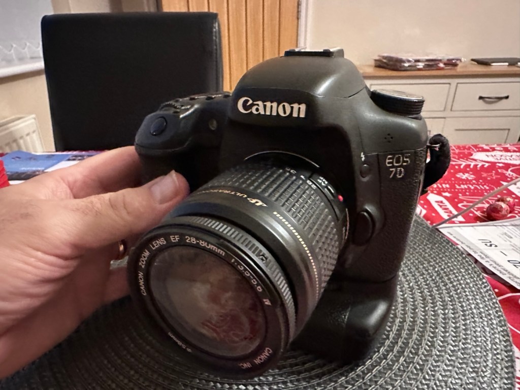
Right it was now time to get a lens on the front and test the camera to check to see if it would write to the card, it’s only a stock lens, nothing special but absolutely fine for testing purposes. Just walking around the house I put the unit into auto, the flash popped up and I proceeded to rattle off a few random shots. And it worked, the results all came up on the rear screen.
Random shot 1
Random shot 2
Random shot 3
To say I was pleased at this is an absolute understatement. The work on the pins has worked and I now have a perfectly well working example of quite a top end camera. There’s no doubt that in the future the camera will require a replacement card reader, but for the moment it’s been given a new lease of life, and whilst I remember to be gentle with the removal and placement of the CF card, let’s just enjoy the camera and its capabilities until that time comes. In the meantime here are just a few, “Randoms” taken to test the card and camera in and around my home.
Just a few random test shots. It works.
Result:
You little beauty
A perfectly fine working unit
Time to give this camera a little buff up. (Clean)
This unit only appears to have taken 1,860 pictures. It is completely unused, and in perfect condition. And it now works. To be honest I feel more confident with this camera than I do with the mirrorless Sony that my wife purchased for my birthday. This was going to become my number two camera, however it’s just been promoted to my number one, as long as that card pin issue and repair holds up, and I have no reason to doubt that it should be a long time before any issues arise. I am confident that my repair has longevity as they say.
I want to give it a good test in daylight conditions in all modes rather than auto. I want to get a bigger CF card maybe a couple of 8GB ones, I don’t see the point in going for the bigger cards just in case there is a read/write issue in the future. It’s just an OCD thing for me, you know what I’m like.
So overall I’m really quite happy and satisfied with this camera. Of all the cameras I was gifted by my good friend Jon, all have been repaired apart from one that was beyond economic repair, even that has been broken down into it component parts, every screw recovered and will be used for spare parts. Nothing, and I mean nothing has been disposed of from this collection of cameras and accessories.
That’s what I do, I don’t waste anything. Ask the wife!
Many thanks for passing by, it’s always very much appreciated.
Not one to give up on a project I have looked at a suitable donor camera and believe I have found one as detailed below. Only difference is that I had to buy two cameras as they came as a bundle. Not a problem as I can always do a separate post on the other one, the two have cost me a total of £15:00GBP bartered down from the original price of £30:00GBP. A bargain! So let’s just call it £7:50GBP per camera.
What the listing stated:
mamiya shutter button is stuck. red light on the right comes on. some external corrosion pictured
ricoh no power at all
EBay
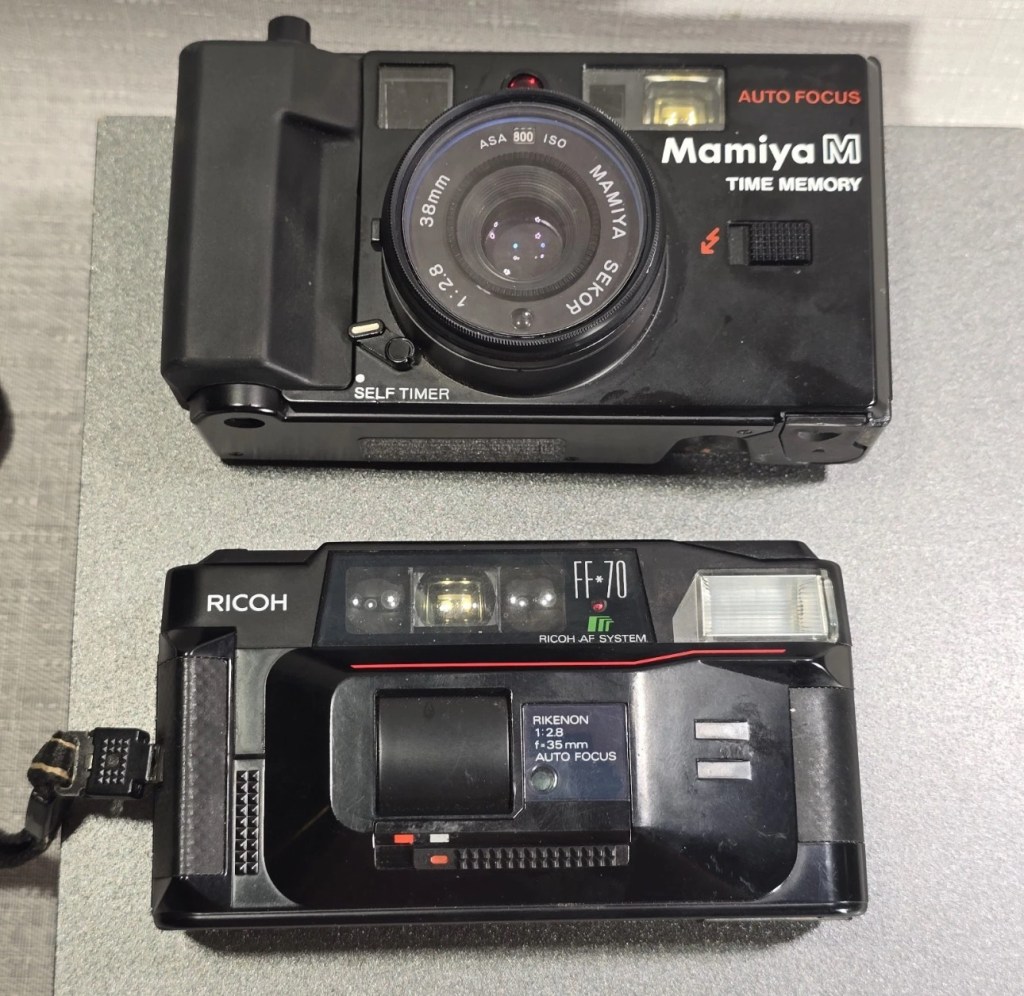
The two cameras
Assessment:
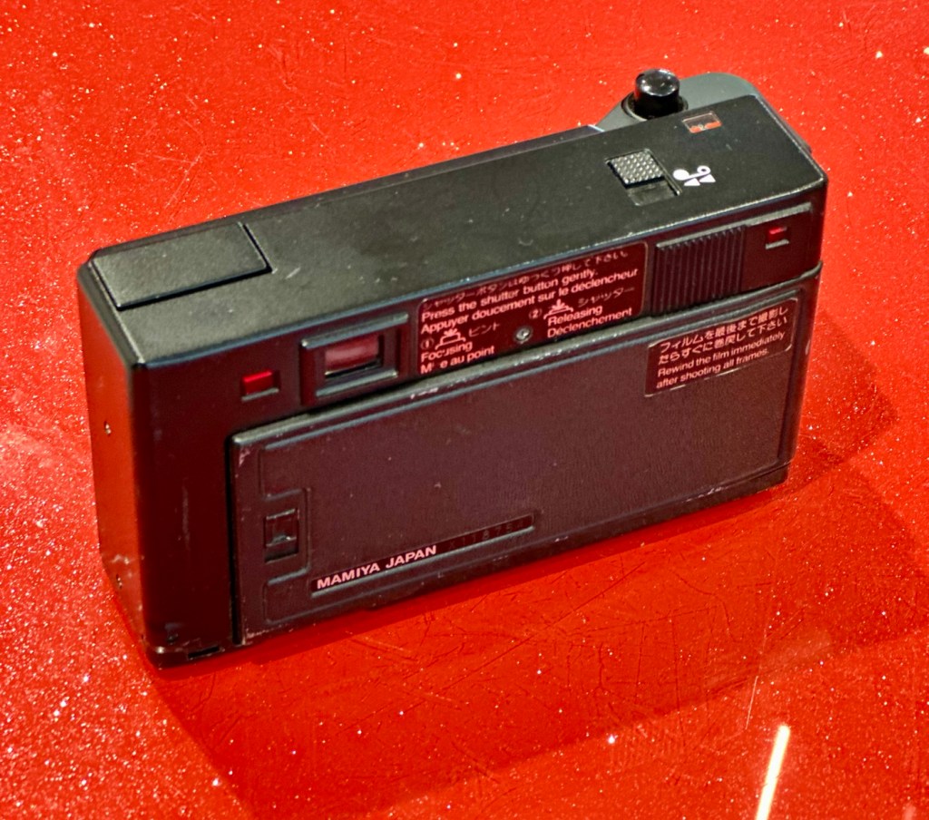
The Mamiya is in quite a poor state, and is the Time Memory version that differs very slightly from the version I originally worked on, it’s essentially the same camera as the Mamiya M, but with an added quartz dating mechanism for imprinting time and date information on the film. This model was the last 35mm camera Mamiya produced before focusing solely on medium format. However the back seems to be a bit rusty whereas mine is in excellent condition, so I will be using a mix of the two units to make the one good one.
Repair:
The Mamiya looks good cosmetically until you open the rear and see the rust around the door, not a problem as I won’t be using this part of the camera. The red light does not come on at all and the shutter button is stuck, that’s for sure. The whole camera is dead.
Let’s get into it.
Once opened all looks ok so I decide to have a search around with the multimeter checking the basic operation. Am I getting 3 volts at the top of the battery barrel? No I’m not. It appears that one of the traces on the positive side of the power input board has lost continuity. For some reason the traces has been damaged, this could be either from corrosion or rubbing on something. The area affected is in the photo with the red ring around it.
The board top rightArea of no continuity
I’ve fixed this immediately using some solder to bridge the gap, I have checked continuity and all seems ok. I put some batteries in and the motor squeals like a banshee and then stops. You can hear the screaming motor below in the short video from its first screaming session through to its proper 80s sounding drone.
The screaming motor through to its repair
I don’t think this motor has run for years and it does not run consistently. I have sprayed it with some contact cleaner and let it soak. I have left it overnight and checked the operation in the morning and it seems to have improved.
I’ve used the original fascia, rear door, focussing beam and flash capacitor from the first failed unit, and apart from a few bits of soldering, plenty of contact cleaner and some silicone grease, I’ve revitalised a failing motor and it is now working as it should. I forgot to mention I used some graphite on the shutter leafs to “lubricate” them. All optics cleaned and camera has been tested without film and is working just fine.
View finder indications are good with light meter operational, motor rewind works, flash and exposure is fine, and the motor advances as well.
Result:
I’m really pleased with this little camera and am pleased I didn’t give up on it. It’s taken two broken cameras to make one good one, and I have a good few spare parts left over to be used at a later date.
Re assembly taking place
The unit looks so smart, the only real issue is the battery door that is notoriously flimsy and lots of references to its poor design can be found on line. A temporary way around this is just to put some tape across it to keep it closed.
That flimsy battery door
Beyond that issue, the camera is a really good looking unit that has cleaned up really well.
The completed camera
I can’t wait to run some film through it to see how it performs. I have a few cameras like this to test so I’m looking for some decent priced film to use, as i do need quite a bit.
As soon as I have some photographs availability I will link to this post accordingly.
Many thanks for following the repair, it’s always very much appreciated.
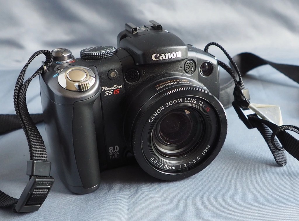
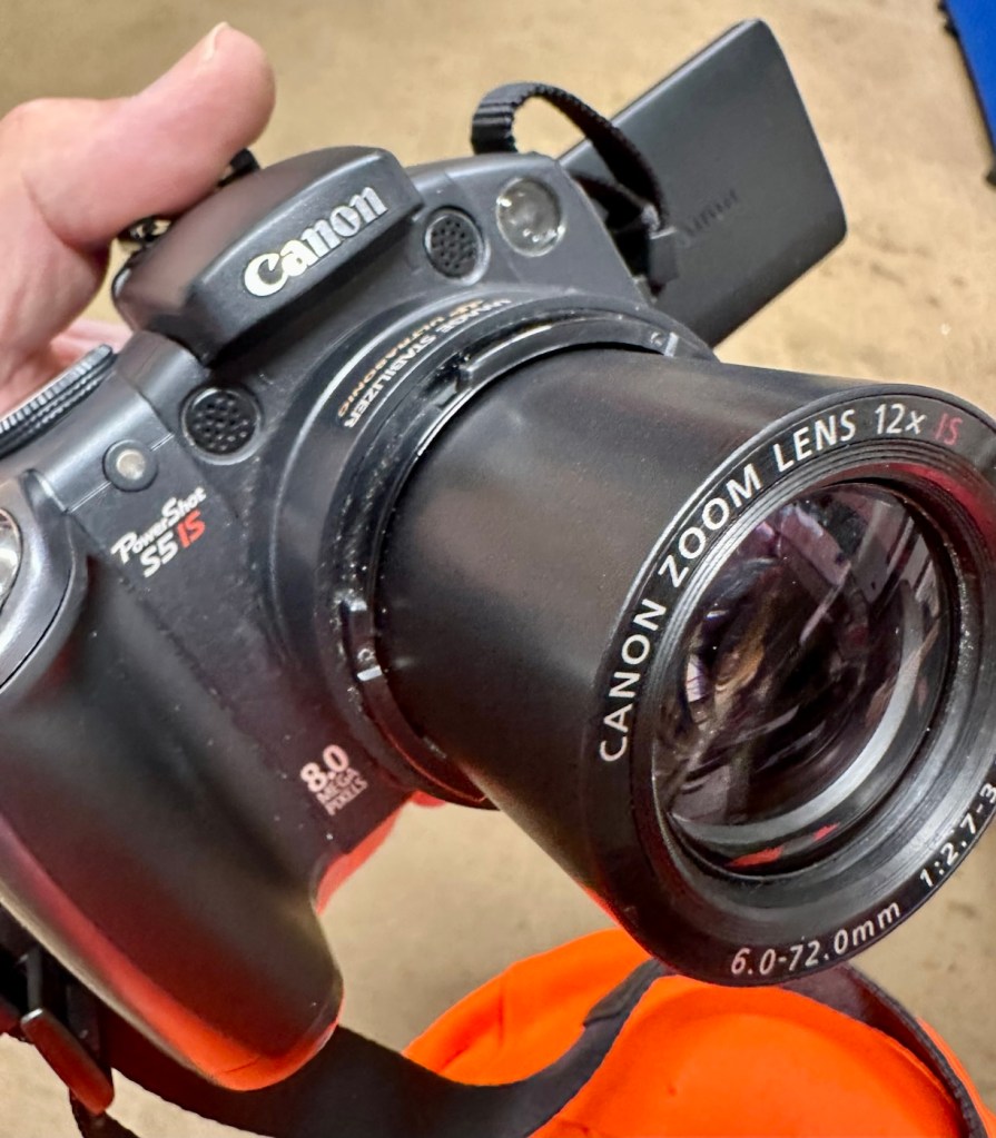
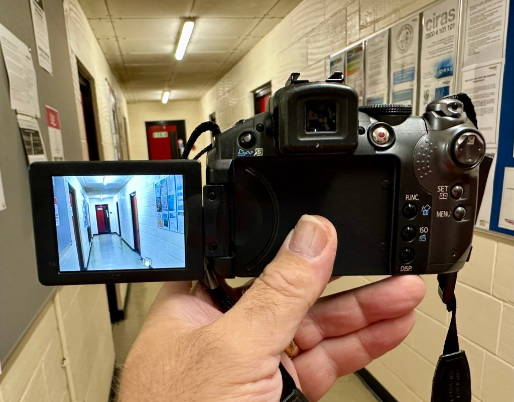
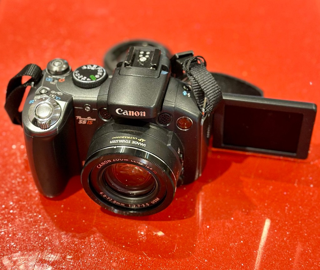
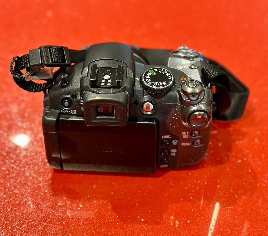
This is a Canon Powershot S5 IS Digital Bridge Camera which is faulty and sold for spares or repair only.
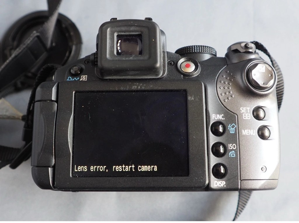
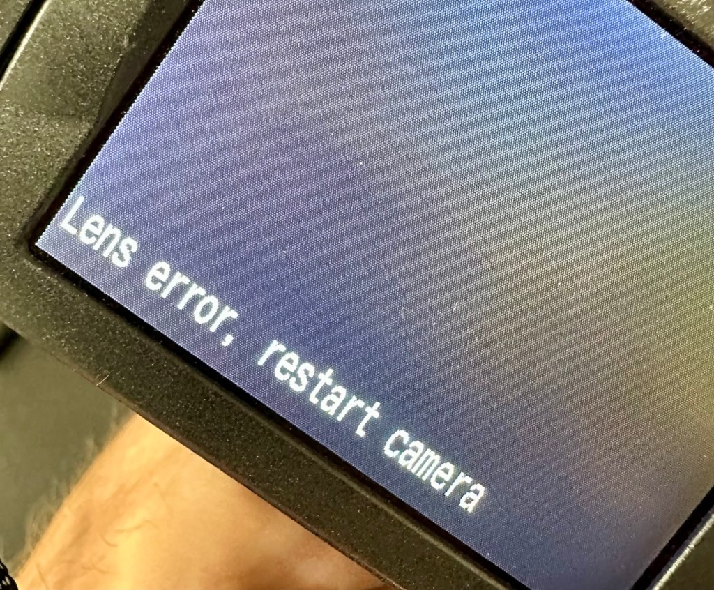
The camera is in excellent cosmetic condition but when switched on there is an error message saying lens error please restart camera (see photo).
It takes 4xAA batteries and SD cards (not supplied)
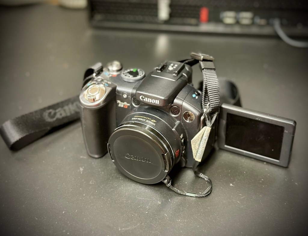
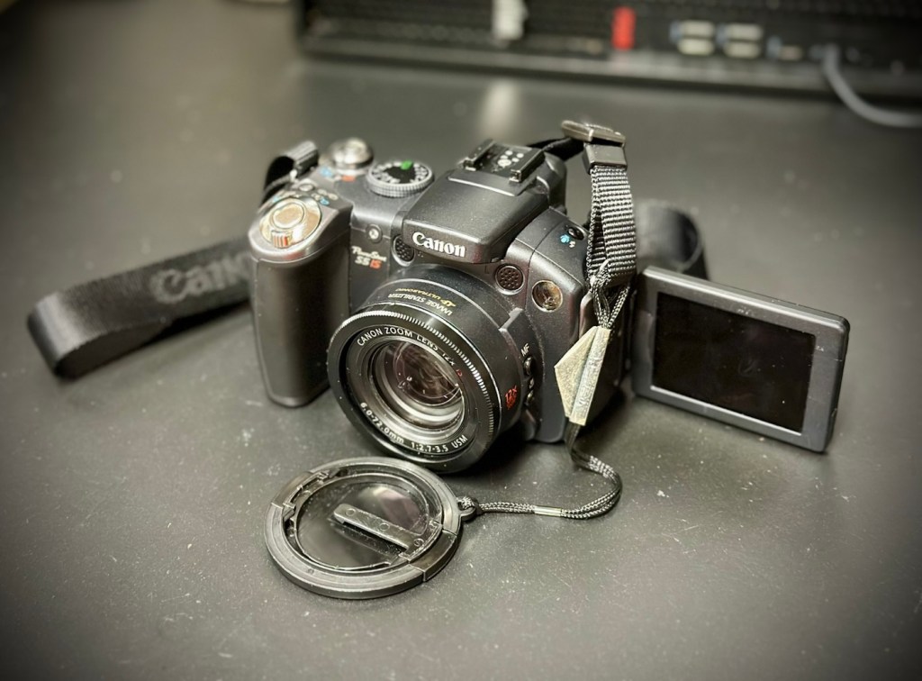
Canon Powershot S5 IS
A little bit about this camera:
Released in June 2007, the PowerShot S5 IS is the successor to the S3 IS model launched in April 2006, which was well received for its optical image stabilization, high zoom ratio and ample movie-shooting capabilities. Like its predecessor, the high-function, high-performance S5 IS features a 12x optical zoom lens equipped with a lens shift image stabilizer and realizes fast, quiet zoom performance by means of a high-speed Ultrasonic Motor (USM).
Compared with its predecessor, the PowerShot S5 IS delivers improved imaging performance through the incorporation of an 8.0-megapixel CCD sensor-increased from 6.0 megapixels in the S3 IS-and an upgrade to Canon’s high-performance DIGIC III image processor from the earlier model’s DIGIC II. Additionally, the S5 IS employs a 2.5-inch high-resolution (approximately 207,000 dots) vari-angle LCD monitor that offers a wide viewing angle to realize a high level of shooting flexibility, and includes a hot shoe for compatibility with Canon EX-series Speedlite flashes.
The new Canon PowerShot model supports the recording of high-quality movies by enabling users to make use of the camera’s optical zoom and Face Detection AF/AE functions. The S5 IS also offers an LP movie mode, which employs a higher rate of image compression to enable longer recording times for VGA movies, as well as high-quality stereo sound, and seamless transitions between the shooting of still images and movie recording.
Canon
I’ve been watching this one for a little while, it looks very good cosmetically and I’m surprised as I was the only one that bid on it. I’ve paid a total, including postage of £8:81GBP and I think that is an absolute bargain. An issue with these cameras has always been a motor/lens error. These motors within these cameras are an ultrasonic motor (USM) and to be totally honest they can be quite delicate and are known to give up as such, if even a grain of sand was to get stuck in the lens gear mechanism. They are delicate souls that don’t really like hard work 😂
A good clean is sometimes all that is needed to get these cameras working again, however I’m not going to get ahead of myself here, as I just don’t know what kind of pain the previous owner has inflicted on this camera. I just hope they have not been too brutal.
Assessment:
Now this is an absolutely beautiful looking little camera in pristine cosmetic condition. The previous owner has in fact been extremely careful and treated this camera very well.
The elephant in the room
The only issue that I can see is the one that flashes up on the screen, continuously when to turn on the camera. Even moving the telephoto/wide switch when starting up does not clear the fault. I really need to get the lens extended to see what’s going on. If I can do that without getting the screwdriver involved then that is even better.
Repair:
The lens remains stuck in the closed position despite there being movement with the lens iris, all other actions are as expected, just no extension of the lens turret. It does sound as if something is trying to move inside.
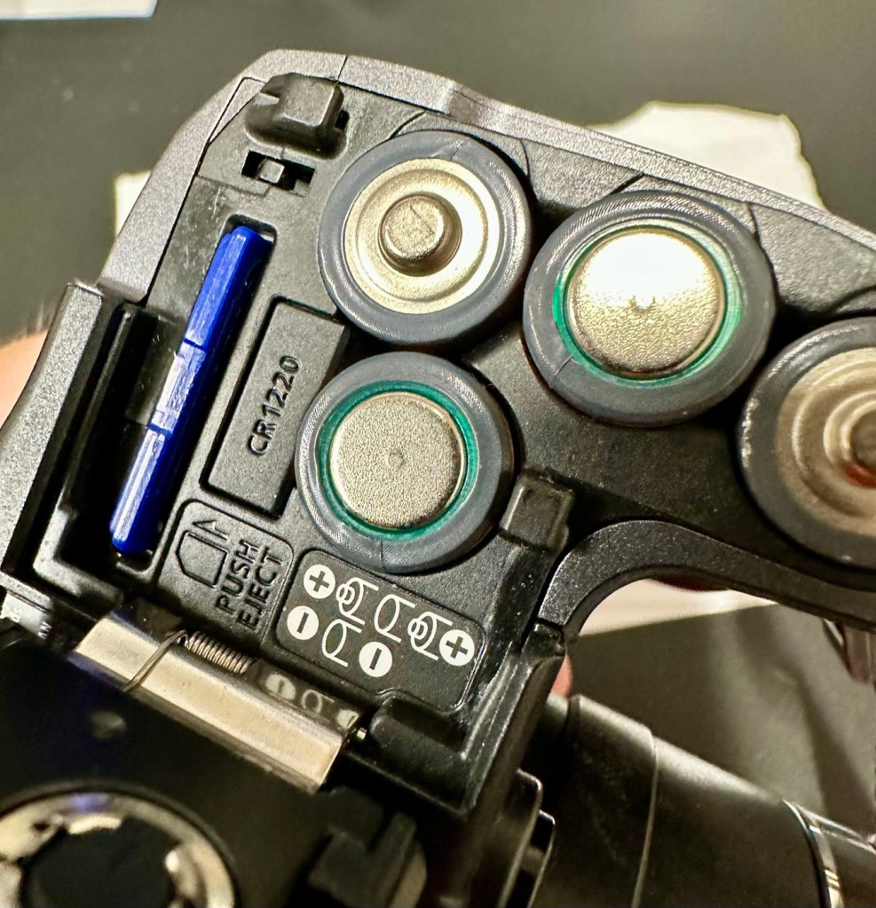
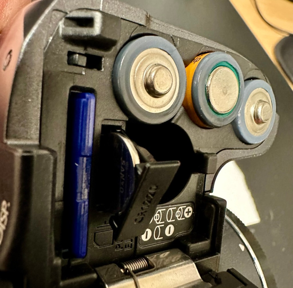
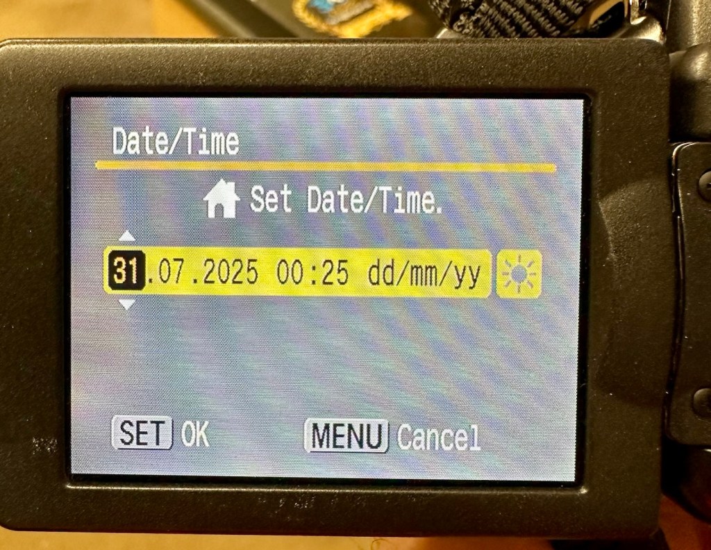
I’ve tried resetting and going back to factory defaults with no joy. I have been noticing though that when i put in a time and date, it is resetting every time i turn the camera off and then back on again. This is usually a sign that the small internal memory battery is dead, and as it’s probably been in the camera since 2007 it’s probably a good idea to change it. If I can find it. That is.
Internal memory battery located
Panic over I have found the memory battery (CMOS) it was located in the battery chamber beside the SD card slot. It’s a small CR1220 coin battery and I have one of these in my battery box, so this will be replaced as soon as I get it home, now replaced all is working as it should be.
Time setResets when powered down
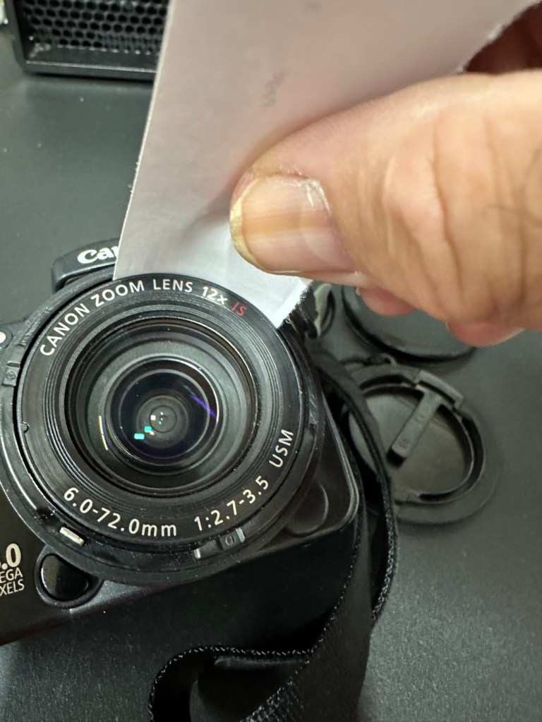
Back to the error. The error is more often than not caused by something, even a grain of sand getting in the turret area and catching in the workings, as these cameras are so delicate. We have to somehow get into the turret area to see if we can dislodge whatever is causing the problem.
Lens turret no movement A strip of paper down the turret
I’d advise against using canned air here, as doing so would most probably dislodge the obstruction, however the route down the turret leads directly to the image sensor and you don’t want debris on that. Careful is the buzz word.
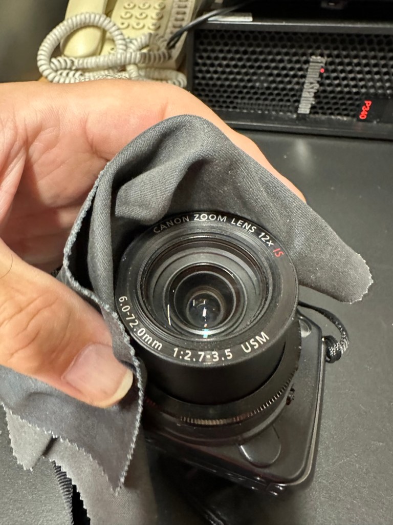
A strip of paper down the turret Released, and a clean with an optics cloth
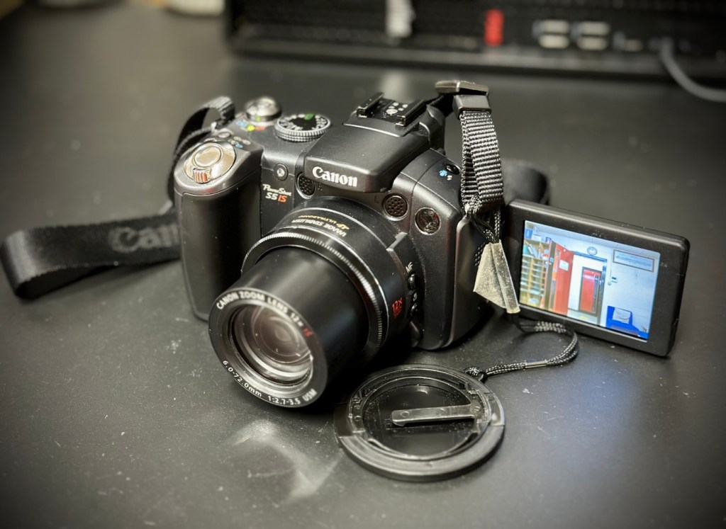
I cut a small strip of paper and feed this down between the tiny gap between the lens and the body. I manoeuvre this around the full circumference of the lens, and as I do I can feel some slight resistance as if something is there. I go around again and that resistance has gone. I turn the camera on and still there is no extension of the turret. At this point I put the mode dial on the camera into video mode and then turn it on. Straight away the turret extends and what looks like some grains of dirt fall from the lens area, at last we have the lens extended and there is an image on the LCD screen.
We have successfully freed the lens turret
I clean the lens turret with an optics cloth and you can see it was very dusty inside, there had definitely been some debris enter this area causing the issue.
I operated the on off button a number of times to ensure the turret motion was smooth, and it was. There are no further obstacles in this area, causing the mechanism to seize.
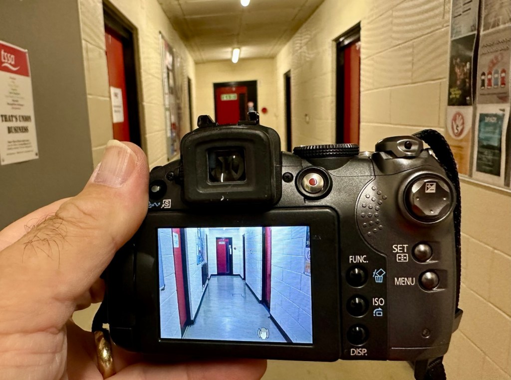
Test photos
I have taken a number of test photos trying out all modes and features and the camera is just perfect.
The camera is now working
The camera operating as it should
I’ll show a few more photos below, once I have been able to download them.
Result:
This camera is simply a little beauty. It is probably one of the best looking of the later generations of bridge cameras but maybe not the best photo quality wise at 8mp. But who cares though, when you are as good looking as this?
The handsome devil
The camera is pristine in my eyes, and for just over £8GBP this is a bargain. These fixes do not always involve a total dismantling of the item, sometimes it is so simple it’s unbelievable. Here I used a piece of paper and a lens cloth, that’s all. Now a camera destined for an old box in the loft and then the tip has been saved to carry on taking photos for a good few years yet. In fact here are a few photos that I have taken randomly around work, and around my garden.
I’m probably going to use this camera with its pivoting screen to construct videos to display on this site regarding future repairs, I’m going to ensure it gets good usage under my ownership.
Did I tell you how much I love this camera and how handsome it is? Oh, I did, sorry about that, I get really carried away with these older cameras, I just wish everyone else could get as excited as I do, and maybe so many of these wonderful machines wouldn’t then, just get thrown out with the bath water.
Thanks for passing by. It’s always most appreciated.
A bit of a different one here, i get into work one day earlier this week, to be told that one of my colleagues in a different area (Nottingham) will be calling with something to discuss. That call occurred today and the discussion was about his home theatre surround sound system that had packed up on him, and would I be willing to look at it for him to see if I could manage a repair. Though it’s something I don’t usually do repairs on, I said why not? I need to look into other areas of repair and as long as it wasn’t urgent and there was no urgency, then I’d certainly look into it for him. It turns out there is no hurry and he will get the item down to me in the next few days.
So I now have a task, that I am really quite excited about. And for obvious reasons I want to do a good job.
Here’s a little bit about this item
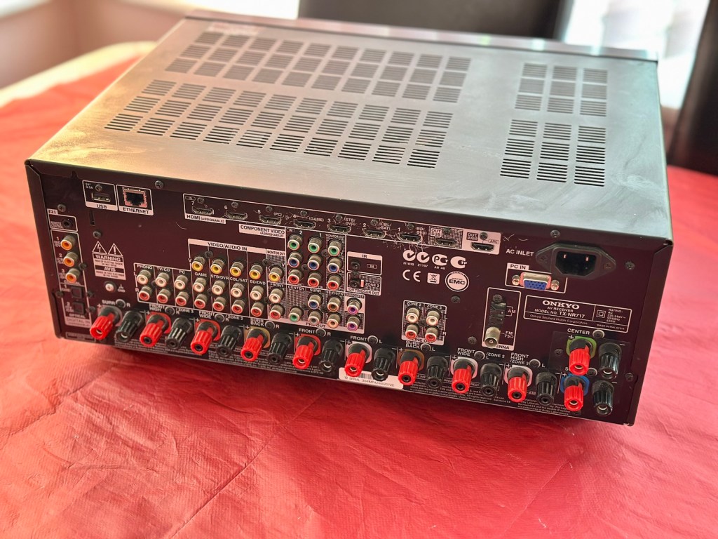
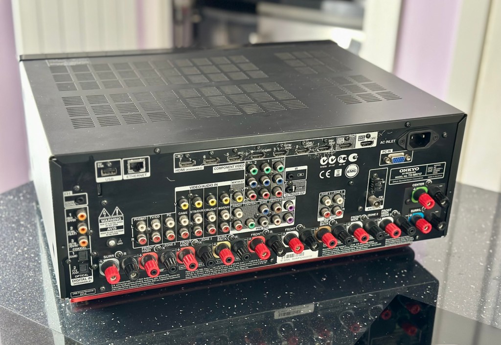
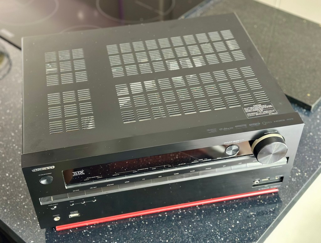
With the power to fill large rooms with THX certified sound, this cutting-edge receiver is ready to integrate and distribute entertainment throughout your home. More than a home cinema processor, the TX-NR717 allows you to access music on PC, stream from MP3 tunes, explore online radio, or connect your iPod/iPhone to one of two USB ports. You can distribute any of these various stereo sources to other rooms for house-wide entertainment. With a total of 10 HDMI connections, this receiver converges HD content from all your components – even your smart phone media via a front side MHL/HDMI – and provides easy input selection with InstaPrevue technology. HDMI also enables intuitive GUI with overlaid quick set-up menu. Video upscaling to 4K, Audyssey DSX seven-channel sound expansion, and Audyssey 2EQ room correction are all included. Sound quality is quite simply the best in class, with powerful WRAT amplifier, three-stage inverted Darlington circuitry, and discrete output stage components delivering an otherworldly entertainment experience.
Onkyo TX-NR717 – AV network receiver – 7.2 channel – black
Release date: April 2012
Onkyo
I’m looking forward to this project, a little out of my comfort zone, but it’s the best way to learn about how these things work. And I need some exposure to these types of systems and the issues that can occur within them.
Assessment:
This unit has just about reached its teenage years, and if this can’t be repaired then the owner will be looking at his alternatives. However replacement units have also grown in both features and price now, so if this current box of tricks can be given an extended lease of life then everyone is a winner, and one less item gets to go to landfill.
I have downloaded both the instruction manual and the service manual, so I am equipped with a full list of components as well as the official schematic diagrams of the circuitry layout. I’m suitably prepared for this one.
The report from my work colleague is that it was working fine up until a week ago when it would just not switch on. He has replaced the two quick blow fuses that he saw when he opened the unit, however the issue still remains. He hears clicking when he turns the system on, this could be an issue in the standby circuit, however I will have to wait to have the unit in my possession to investigate this any further.
Straight to the point…just how I like it
Just got a message from one of my colleagues at work to say the parcel from Nottingham has been collected. Just love the straight to the point way these guys inform me of any safety issues and concerns they may have 😂
More surprises
And on opening the box, more surprises. Biscuits, they are my downfall, and don’t ask about the Aubergine, we won’t go there, that’s a private joke 🤦♂️
A bit dusty
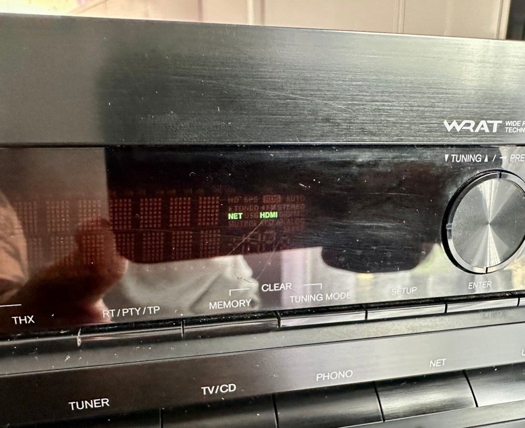
Right, serious head on now and I’ve plugged the unit into the mains and without touching anything at all, all I can hear is a metronomic clicking that appears to be emanating from the power board circuit area. This will be my first port of call.
Repair:
There are two well known issues regarding these units and I am going to look at both of these before getting in any deeper. The first issue is around the relay and its associated 150 Ohm resistor on the main power board, the second issue is around a defective capacitor on the standby board, and eliminating one issue will either highlight, or clear the other. If both issues are addressed with no change to operation, I will have to look in to the issue a little deeper.
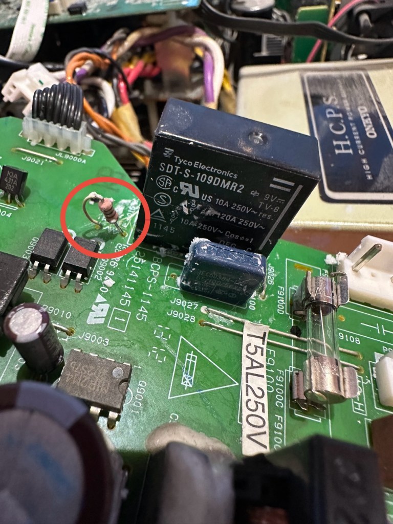
Issue one relates to a problem with the relay on the main power board. Most people don’t realise this but pressing the power button on an Onkyo receiver does NOT turn off the power. The power button merely sends a signal to the MAIN CPU telling it to close a relay (to turn the system on) or open a relay (to turn it off). When you press the power button on an Onkyo and nothing happens (no clicks, no brief lighting up of the front panel) the root cause is often a blown coil in the main power relay.
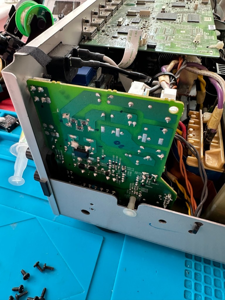
Main relay is the item under the thick coating of white silicone at the top of the picture
Beside the relay to the left is a resistor that should be reading 150 Ohms. This particular one is reading 144 Ohms so is reading a bit lower than expected. This could be sufficiently low enough to allow the relay to fail. So at this point this looks like a possible point of failure. Either way they need to be replaced before we can advance any further.
Silicone removed. The faulty resistor is within the red circle
I need to obtain these parts, the relay will need to be shipped from China, and I need to check my resistor stock to see if I have a suitable replacement resistor. The relay also should have a similar resistance to the resistor beside it, the healthy range for the relay is between 80-200 Ohms.
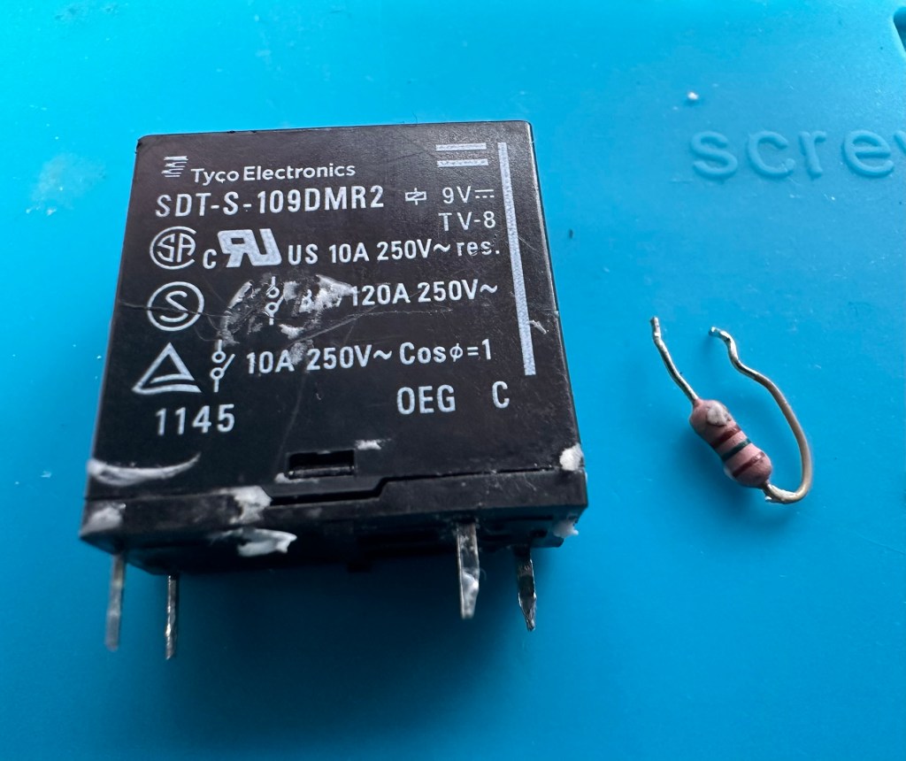
Both components removedThe components
I have removed both components from the board to test them out of circuit.
The resistor beside the 9v relay is a 150 Ohm rated resistor. This one reads at 144 Ohms and is to the lower end of the rating of +/- 5%, it would probably suffice, but i’m going to replace this one just in case. The only other resistor in this circuit is a 47 Ohm resistor and that reads exactly as it is rated, so there is no issue there. I believe the bone of contention here is that the relay is 9v sitting upon a 12v power rail. This is probably the reason issues have occurred with these units in the past, and looking at a number of forum posts, it is quite acceptable, even recommended to use the higher voltage 12V versions. I’m sticking to the original design on this repair though, I can only presume the 150 Ohm resistor placed just before the relay has something to contribute in controlling the operation of this relay. Maybe that’s a design fault within this model, I just don’t know!
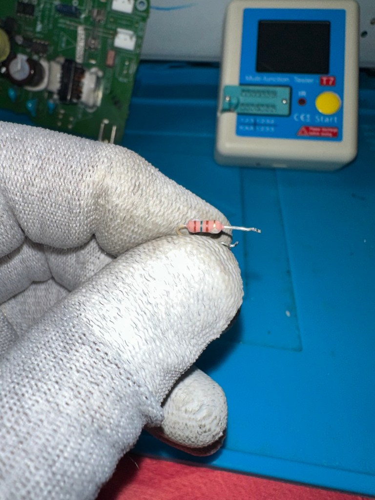
144 OhmsThe resistor I will replace
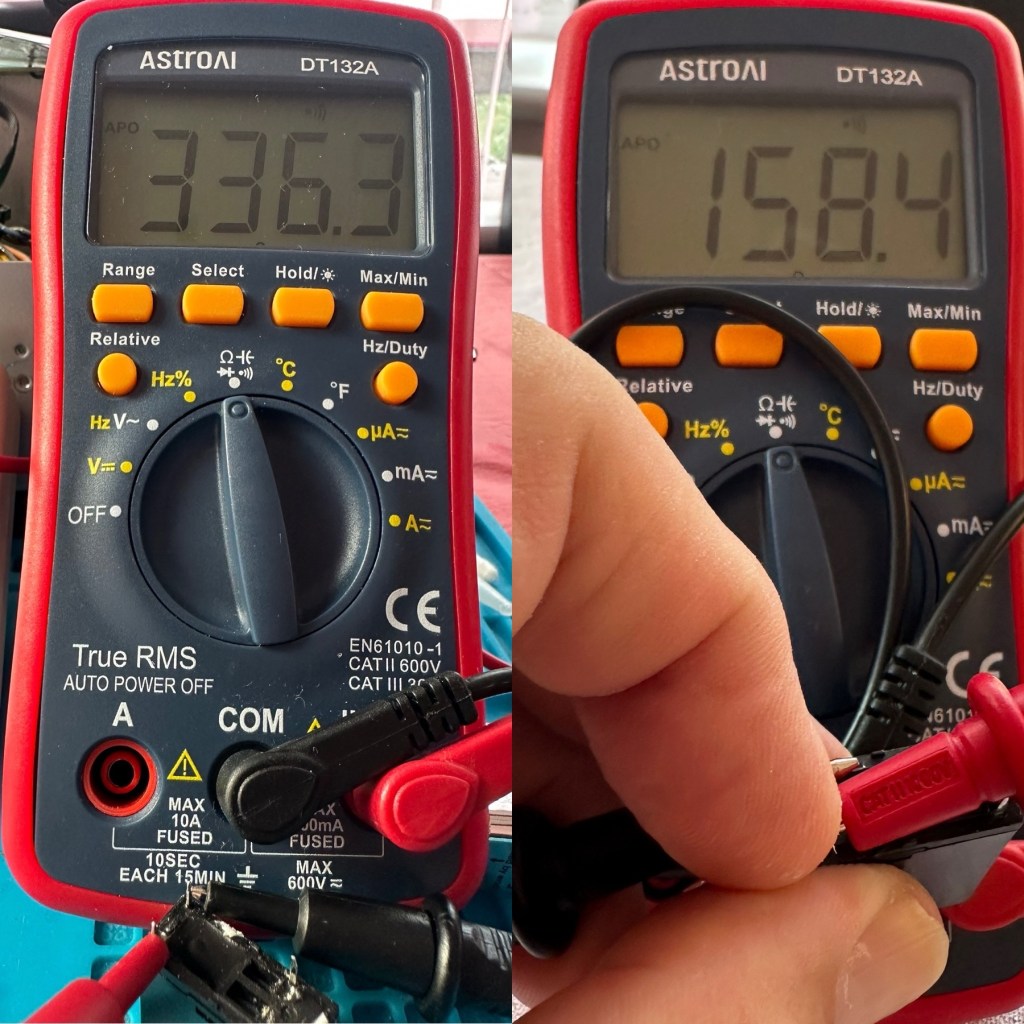
I have tested the relay using a multimeter and a 9v battery. I have used the battery to short across the power poles where I can hear the relay clicking, but when the relay is on there is no continuity across the other two pins when there should be, this isn’t happening so I suspect this relay is stuck in the open position. The Ohms rating across the pins shows 336 Ohms, so i am lead to believe this could be a problem with the coil inside it, as it shouldn’t really be that high. I understand from what I have read, that a rating between 80-200 Ohms is classed as acceptable, and outside this range could indicate that there is an issue. I’ll just have to wait until the new relay arrives and carry out some tests to see the comparison between the old and the new relays.
336 Ohms is that an issue?
I’ve dismantled the cover from the relay to get a look at the coil. In the little video below you will see the coil switching, however you will also see the contacts meeting but there is no continuity. The contacts have a coating of contamination on them probably from age or arcing, it looks like a carbon deposit, as when they adjoin there is no contact made, no flow or continuity, unless you put light pressure on the contact and then you get the continuity. It is at fault, it shouldn’t be doing this. A clean of the contacts might breathe some life into it, however give it a couple of months and you’d probably have to remove it again, and the contamination isn’t the only issue, don’t forget the relay reading that appears too high. A new relay costs less than £4:50GBP delivered from the other side of the world, so I might just as well go for a new relay. It makes sense.
Inside that failed relay
I’m not going to venture any deeper into this unit yet, not until these components arrive and I can get them back into place. I want to move through this fix confidently and slowly, have a better understanding of what is going on and not leave myself confused with bits and pieces everywhere, clueless to what is occurring. I wouldn’t achieve anything by working like that. Knowledge is king here and I’m here to learn. And I do now have the schematics available to follow.
I’ll have to wait about 2 weeks for the relay to arrive so I’ll just have to put this repair to one side and on hold until then.
Ok the new relay has arrived and the first test I did on it was to take an Ohms reading of the coil side. Now if you have paid attention, you will have seen that the old relay was reading 336 Ohms when it should be somewhere between 80-200 ohms. This new relay is reading 158 Ohms and I feel a lot better about that, it falls right in between the expected spec.
Old relay reading on the left versus new relay on the right
And if you want to see the relay actually working and displaying continuity then have a browse at this video below, the polar opposite to the first video I posted above 👆
The new relay with good continuity
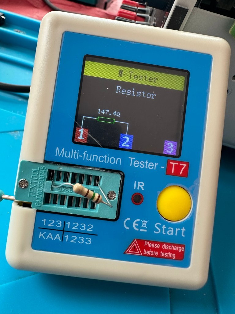
The resistors I ordered have now come through and have been tested, I have a couple of candidates displaying better test results, so we can now look at getting these two components back in place to see what occurs.
I’ve put in place a new resistor, slightly higher value than the previous one coming in at 147.4 Ohms. It falls within the 5% tolerance so should be fine.
147.4 Ohms
The relay has been soldered back in place, really simple just four points to solder and we can now reassemble the power board back into the chassis.
Attach transformer and ac jumpers Board secured back into chassis
I’ve taken the unit into the garden at my wife’s request, as I have to use some high pressure air to give it a good blast to get rid of some dust and furballs. This has worked well and quite a dust cloud was witnessed across the garden, it’s fair to say it’s a lot cleaner inside than it was.
I’ve now put the case back on and the unit is now sealed from prying eyes and inquisitive fingers. I’ve given the entire case a good polish and I must admit it is looking nice and shiny and very presentable. I just have to hope and pray that it turns on. I see no reason as to why it shouldn’t but you just never know. You can always fix one problem only to be chasing it around the system as it develops into another fault, repairs can sometimes go like that.
Let’s plug it in and see what happens 🤞
Result:
I’ve plugged it in and turned the power on. No bang, only silence, just a single click when the power went on, this is good. When the power is turned off you hear the standby relay do the same, all is as it should be.
Front RearFrom above
The standby relay has clicked in when turned on at the power socket, and is not repeating that metronomic sound that was there originally. Superb. Now to turn the power button on, on the front panel.
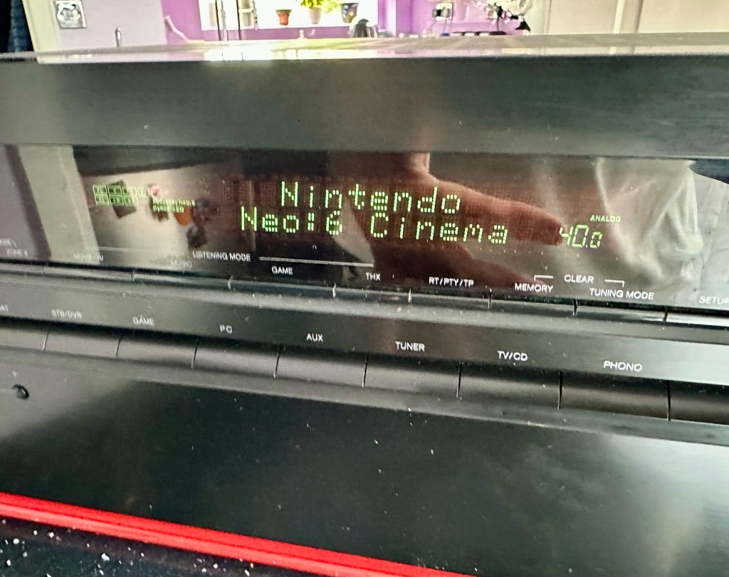
We have a display. Excellent it is working.
StandbyDisplayAll buttons operational
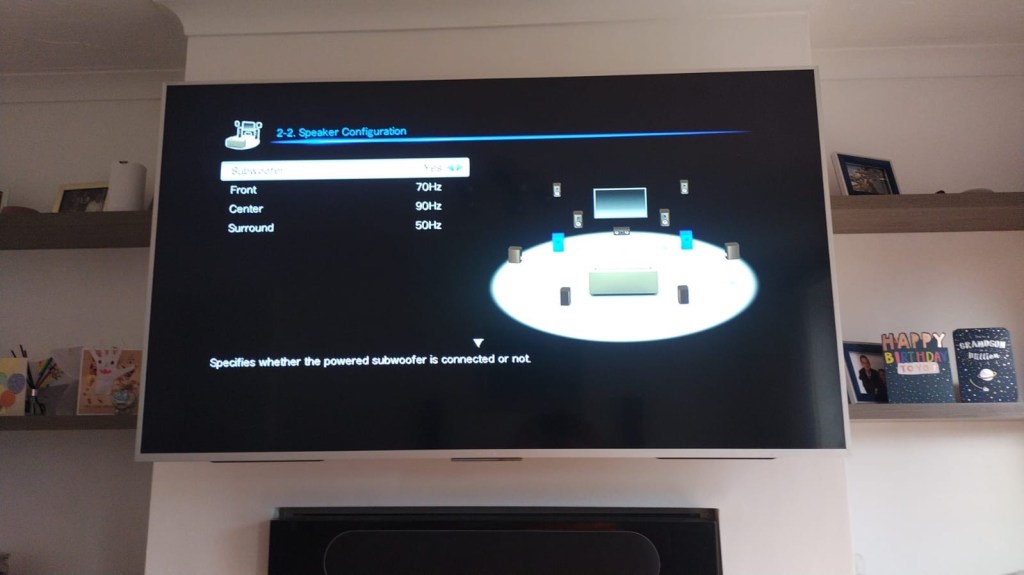
All buttons are operational, I don’t have the surround sound speakers as they are at the owners house in Nottingham, i also don’t have the remote here that also allows me to do other tasks, however that is not important as the unit is now operational and displaying what it should, and once it goes back into his media wall with all his speakers and other related sound and Av equipment, i am confident beyond doubt that it will be operating just as it did prior to this issue developing.
I will be handing it back with the advice that should the issue occur again we look at updating the relays with new 12v versions to replace the current 9v ones. But I doubt the problem will re occur, and this repair should see out the next few years at least and by then this unit will probably be sold, or passed on to someone else when he decides to upgrade his system.
Below is the little video I sent my colleague showing him the unit now working
It’s now working
But for now, it works. I am pleased as punch with this repair as I have stepped out of my normal comfort zone here. I have been extra vigilant, studied many a schematic diagram and learned a lot from this project. I didn’t rush ahead of myself and took this repair one little bit at a time, testing all along the way and addressing each issue in the order that it has arisen. And I’m damned happy with that.
It’s been a learning project for me, and I’m glad I’ve undertaken it. Life is for learning, and I’m living that life.
Many thanks for passing by, as you well know it is always very much appreciated.
Edit:
Today the 29th July I have had a message back from my colleague to say that he now has the unit back in his media wall. And I’m pleased to say it’s working perfectly. He’s very pleased and so am I.
Back in place and working fine
He’s pestering me to bill him, but I’ve told him that I’m only taking one currency and that’s not money or crypto. No, my method of payment will be in Biscuits. I told you I’m a Cookie Monster and this entire repair only cost just £4:17GBP. That’s not a lot of Cookies, but it’s credit in the bank if these guys need any further repairs carrying out. Word of mouth, works wonders.
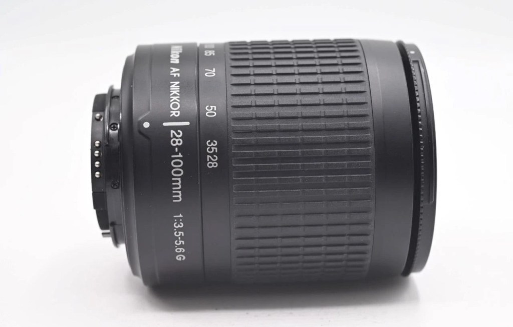
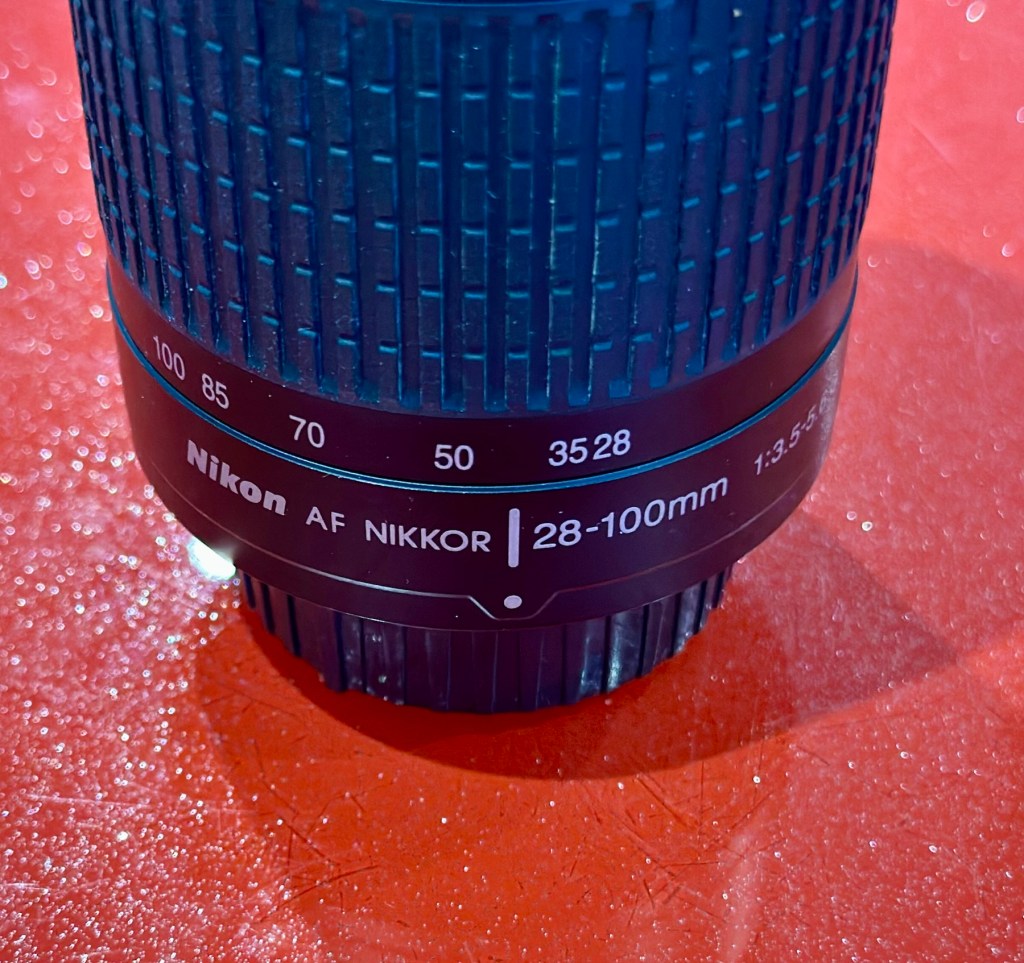
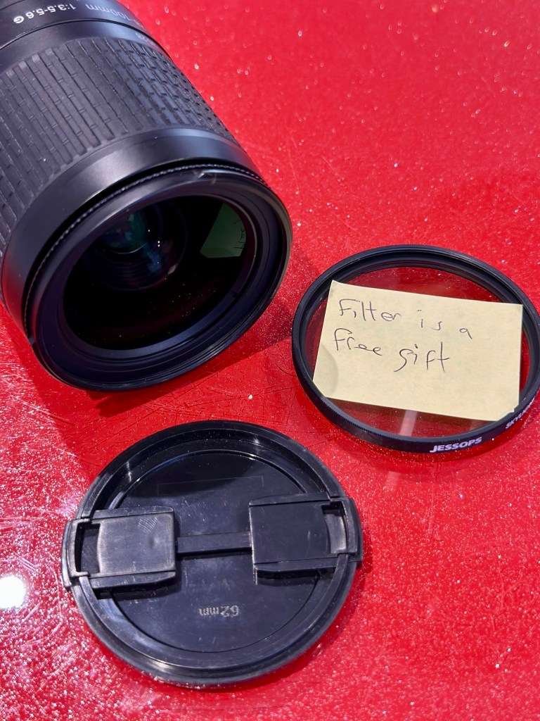
Nikon Nikkor 28-100mm Zoom Auto Focus Lens F3.5-5.6 G
It will autofocus with: Df-D1-D1x-D1H-D2-D2x-D2xs-D3-D3x-D3S-D50-D70-D70s-D80-D90-D7000-D100-D200-D300-D300s-D600-D610-D700-D750-D780-D800-D810-D850-D7000-D7100-D7200-D7500 & Fuji S1, S2, S3,S5
This lens will not autofocus with : D40-D40x-D60-D3000-D3100-D3200-D3300-D3500-D3600-D5000-D5100-D5200-D5300-D5500-D5600 as these cameras do not have integrated autofocus motors in their bodies, but it will still work with manual focus and auto exposure as it has a “chip” mount.
It will also work Nikon 35mm AF film cameras: F80, F90/90x, F75, F70, F65, F60, F55, F50, F80, F90/90x, F101, F100, F401.
Comes with front / rear lens caps
EBay
Anyone that has followed my recent repair of the camera: Fujifilm Finepix S2 Pro will be aware that I purchased a lens as a test lens for working on some stock that required a Nikon mount. I went cheap and purchased a lens that was so badly affected with lens fungus that it will require a deep clean and some TLC. Anyway, it allowed me to test electrical contacts and all the menus, and that was about it, it served a purpose there, but taking a picture was like looking into a deep fog, it was hopeless. Anyway that lens is now set aside and will become one of those projects to dig into on a long winter evening…or two, or three.
As I have a number of Nikon based cameras needing assessment on the horizon, some with sensor issues, i have made the decision to pay a little more for some quality, from a company called AP photographic who specialise in quality used equipment, a company that is based close to where i used to live down in the south. This Lens has cost me £58:95GBP including postage, a fair but good price for some peace of mind. This post will not be a repair post as there is nothing wrong with this lens, it will be more of an assessment of the lens when used with the Fuji S2 pro i featured in a previous post.
Nikon Nikkor 28-100mm Zoom Auto Focus Lens F3.5-5.6
I’ve put this post up to show the difference in the pictures taken on the S2 with both the old lens as well as this lens. I think the results will show quite a noticeable contrast and confirm just how restrictive a lens is when it is infected with a fungus problem.
Assessment:
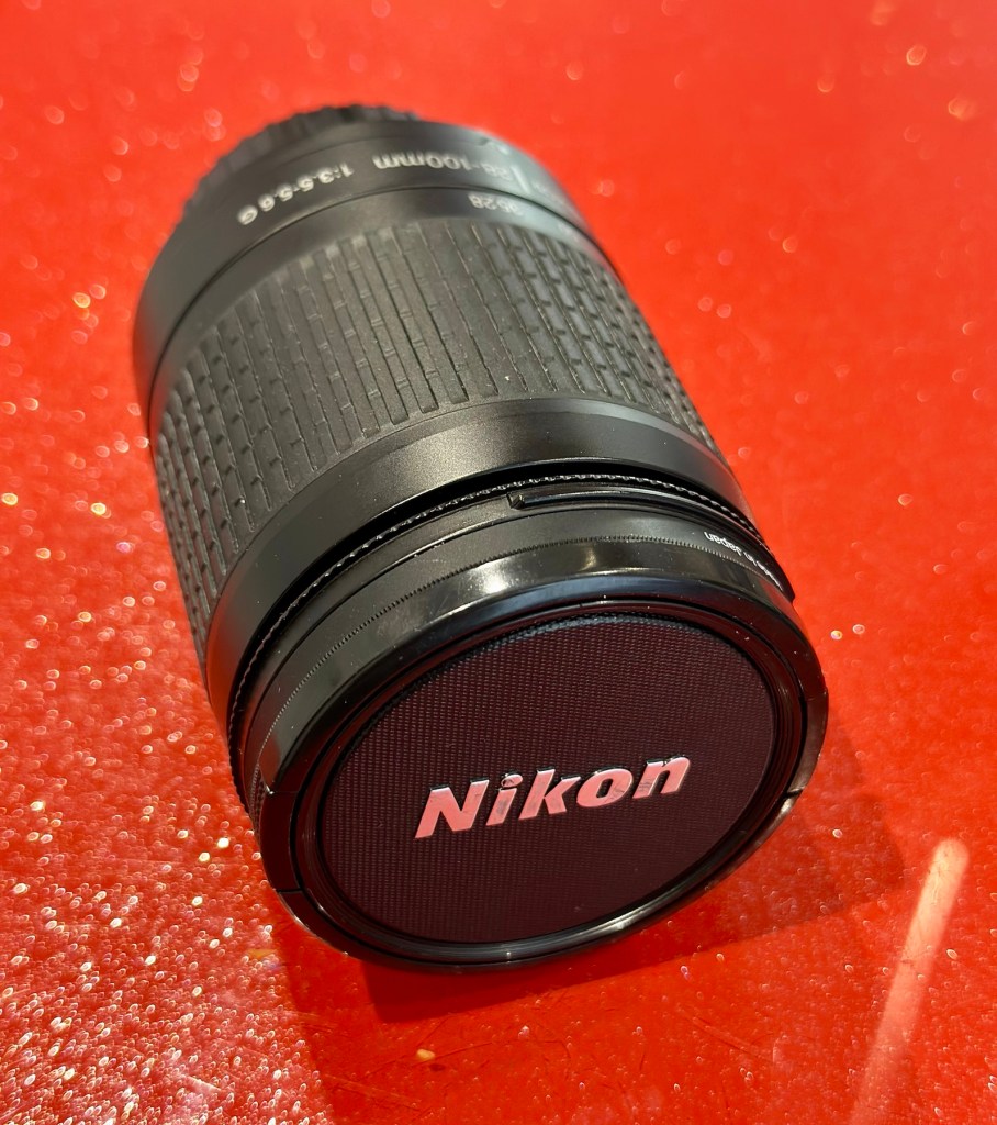
The lens has arrived
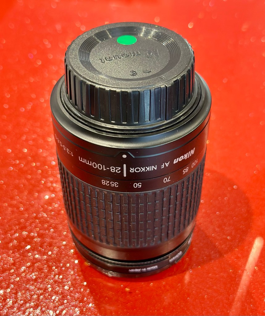
The lens arrived within a couple of days and is in perfect condition. It has a lens cap and bayonet cap so is perfectly protected against dust dirt and damage from foreign objects. And when the lens cover is removed there is another little surprise, a post it note saying “Filter is a free gift” that just happens to be attached to a daylight filter. Nice little touch 👌
Nice touch
Lens is a perfect fit, no aperture ring on it as it is fully automatic, full autofocus. I’m not sure how the flash will work with this lens though when I use the Fuji S2 Pro, as that body works best with a fully closed lens aperture, but I’m sure I’ll be able to work it all out and get it functioning as it should. And I did, i played with the Aperture settings in “A” mode and it works just fine. It’s faultless.
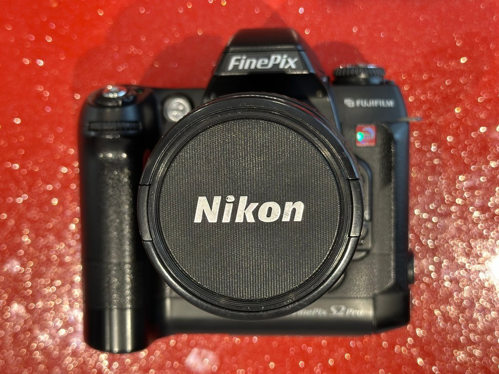
Attached to the Fuji S2 Pro
That said on the S2 it not only looks good, it takes good pictures. Compared to the lens I last used this one is crystal clear, not a bit of fungus no aberrations and not a speck of dirt. This is a good lens and will serve me well for the purpose of testing other equipment I have awaiting attention. I think I’ve purchased a good example here.
Result:
I can confirm that the Fuji S2 Pro does not have a thing wrong with it and is working perfectly. All modes, all conditions are performed just as they should be. This lens is gorgeous as it is so clear and has been so well looked after. I believe this whole unit will be the one I wander about with when i go out on my walks. I can’t wait to take some serious photos to post.
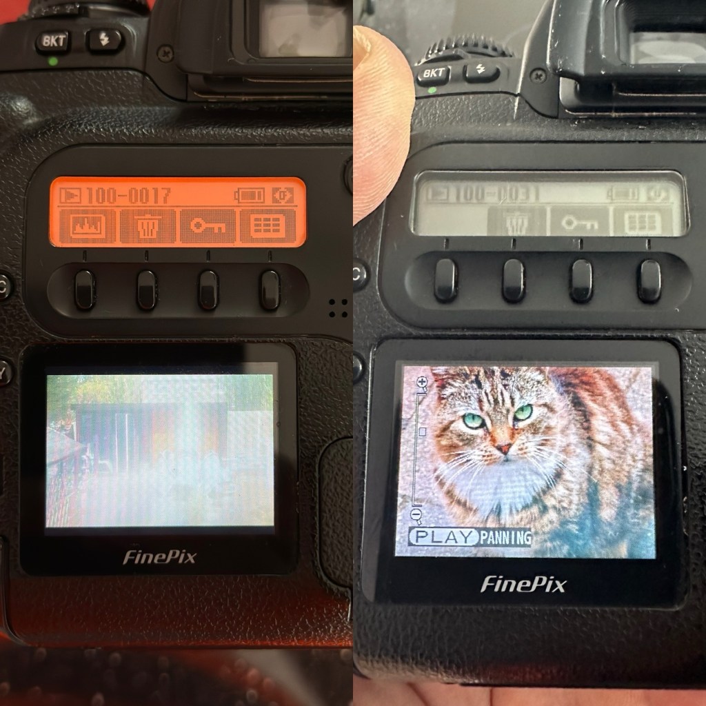
A quick comparison fungus lens v clear lens as seen on the camera LCD screen
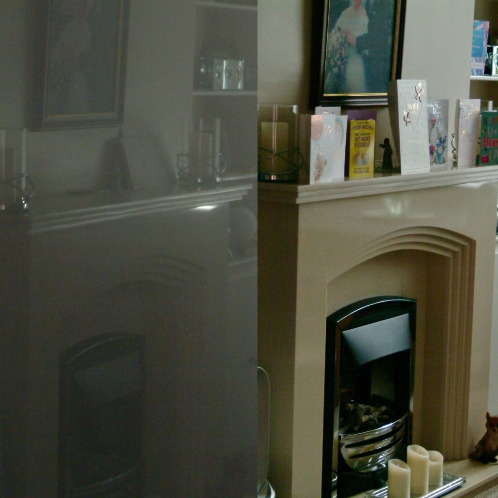
I took some pictures just randomly around the home setting with the old lens to show how foggy things were with the lens fungus. I have tried to take some more photos of the same locations with the new lens as well to just show how they compare and these can be seen in the pictures grouped below.
Before and after pictures, what a difference the fungus has had on the results.
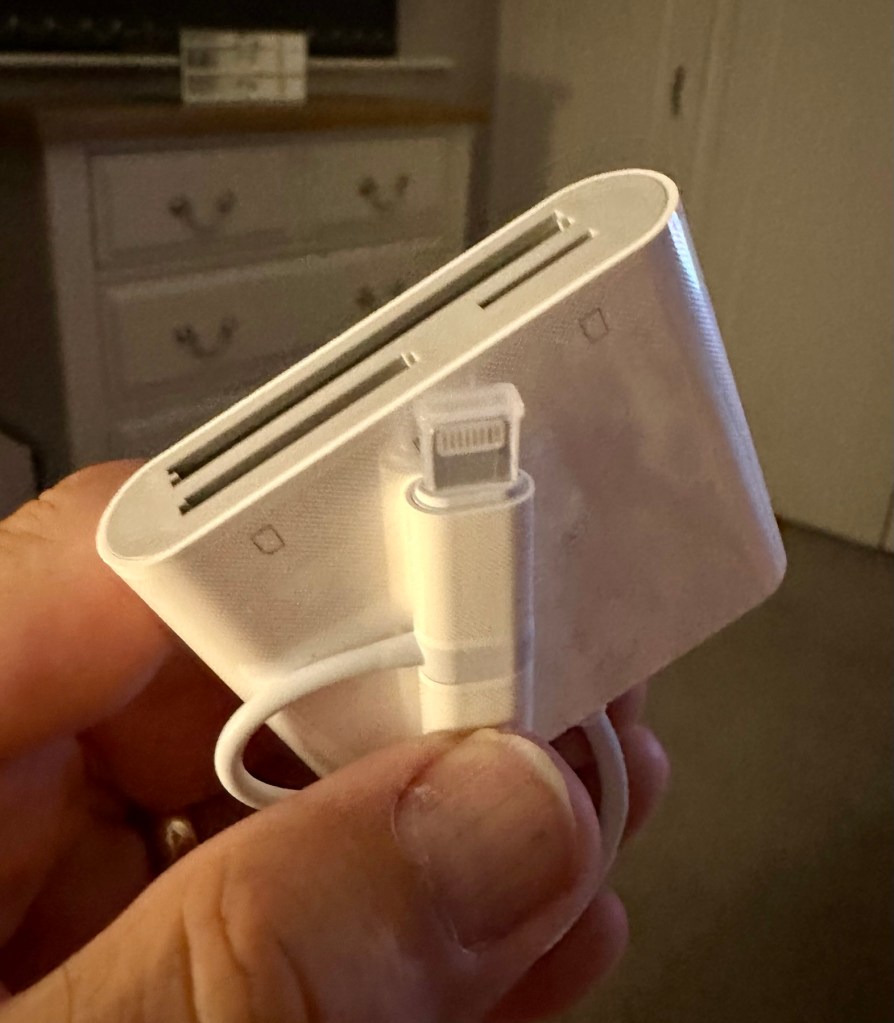
All these pictures are on an old CF card so it is a bit of a palaver to get them on to new technology, but it is doable, it just takes a little time, and this gadget allows me to load numerous card types even the CF cards direct to my iPhone via a lightning connector. It also has a USB-C connector for other phones. It works really well as you can see in all the pictures in this post.
Multiple media cards direct to my iPhone
And below are a few random photos taken on the S2, it has a good black and white mode but is quite heavy on contrast. Post editing would probably be recommended, but to be honest I really love its moody appearance.
4 random photos in and around the house. And Tabs the feral cat popped by
This camera and this lens have proved fantastic. I know you can get far superior picture sizes and quality on a basic mobile phone, but where the heck is the fun in that? This camera cost me £8:00GBP. Just £8:00. And it is a superb camera that will be going on many trips with me as I just love it and how it looks. I now know it intimately after reading up on it and testing it, and cannot wait to put that knowledge to use.
Cameras are better than mobile phones. Old ones like this are fun, and an absolute privilege to use. It’s not all about the Megapixels, just remember these old cameras were the ones taking high quality professional pictures back in their day. Just because time moves on, and just like an elderly old lady or gentleman, they should not be discarded because they no longer serve a purpose. Respect the older technology, learn from it and you will ultimately become a wiser person yourself. Oldies rule! Never forget it. 👊
Thank you so much for passing by. It’s always very much appreciated.
ALL ITEMS IN THIS LISTING ARE FAULTY FAULTS MAY VARY BETWEENS ITEMS
SOLD AS IS
NO RETURNS
EBay
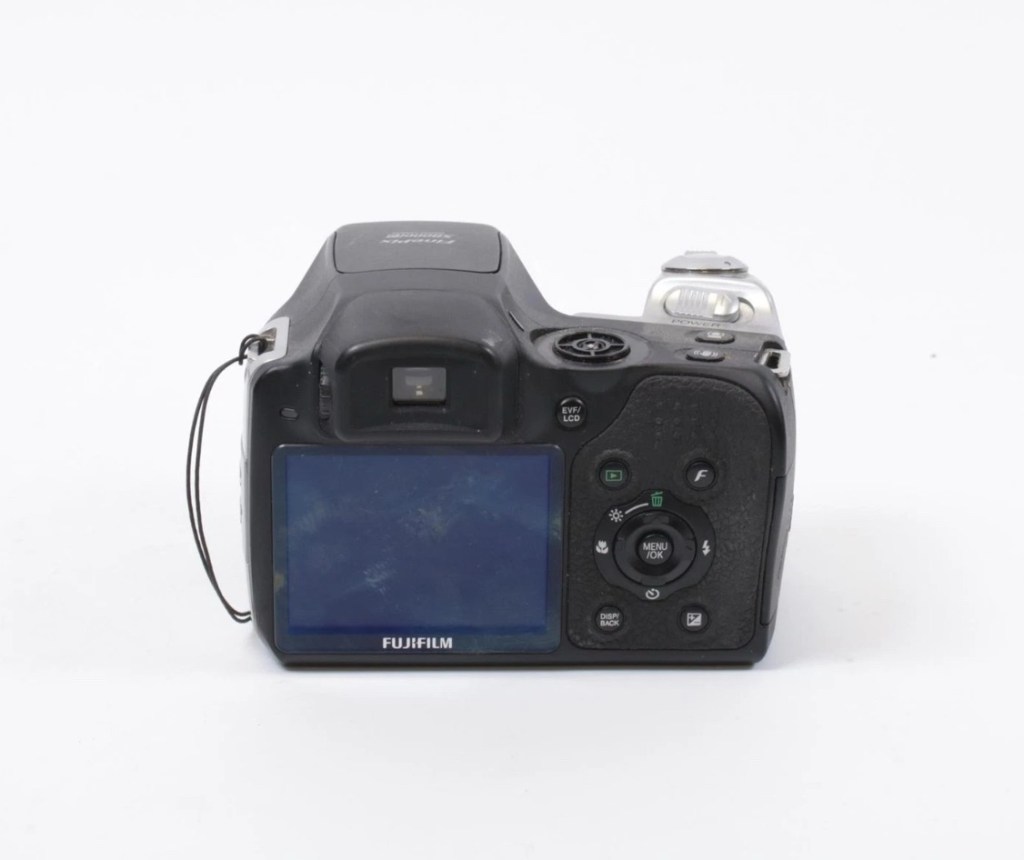
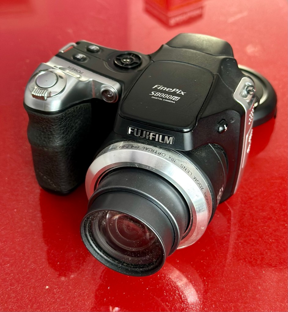
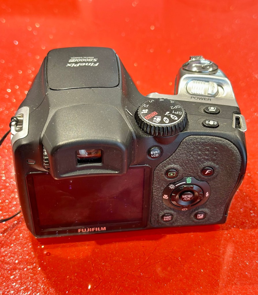
Fujifilm Finepix S8000fd
I’ve purchased three cameras as a job lot in an auction. All of them have issues but the issues have not been clarified. This is very much a “Suck it and see” auction where I get what I’m given. I’ve paid £24:22GBP for all three and that includes free postage. I’ve purchased from this seller before who is a bonafide Camera business based in South Wales. He has no time for faulty items though, quick in and out is his way of working, no time to fix stuff. I’ve got three good cameras in this bundle and this works out at just about £8:00GBP per camera. And where can you get cameras like this for those prices nowadays.
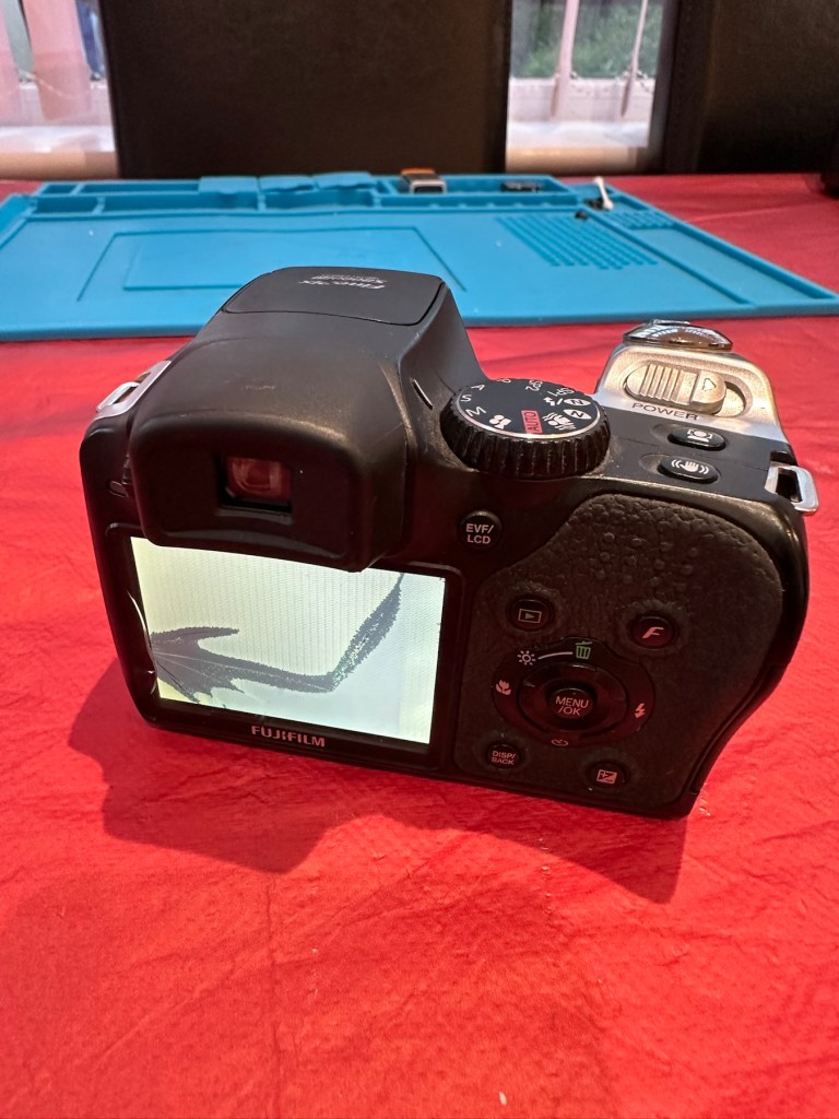
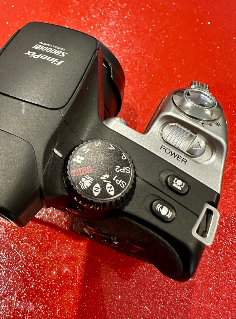
I really don’t know what the specific issues are with this camera, only that it appears to have the mode selector dial missing from its top. I guess we will just have to wait it’s arrival for a full assessment. In the meantime here is a little bit about it.
With the release of the FinePix S8000fd, Fujifilm brings to market a smart-looking digicam with an 8-megapixel imager, one of the longest zoom lenses in the market plus a compact, and relatively light, camera body. The cheapest of three similarly featured long zoom cameras in the current market (see table below for a feature comparison), the S8000fd has the distinction of being able to use both xD-Picture Card and SD cards (including SHDC), which are fitted in a single dual-format slot. Release date July 2007.
Photo review newsletter
Assessment:
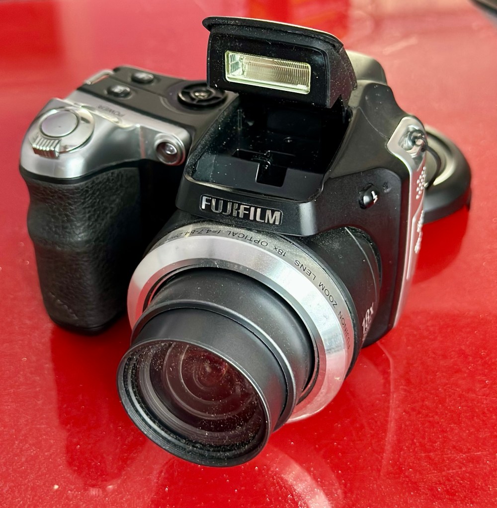
Well, to be honest, for potentially the worst camera in the box of the three that were purchased, it works just fine. Apart from that missing mode selector dial on the top of the camera. You have to use a pair of tweezers to get each mode to appear, but they are all there and the zoom and flash all work and it takes pictures fine, just as it should.
Tidy unit – workingFlash operates All menus available Mode dial – missing
Apart from the issue with the dial, all that is really needed is a little clean up, and even that isn’t that bad.
It does not justify being used as spares and is far too good to just be disposed of. I’m going to try and repair this.
What a bonus!
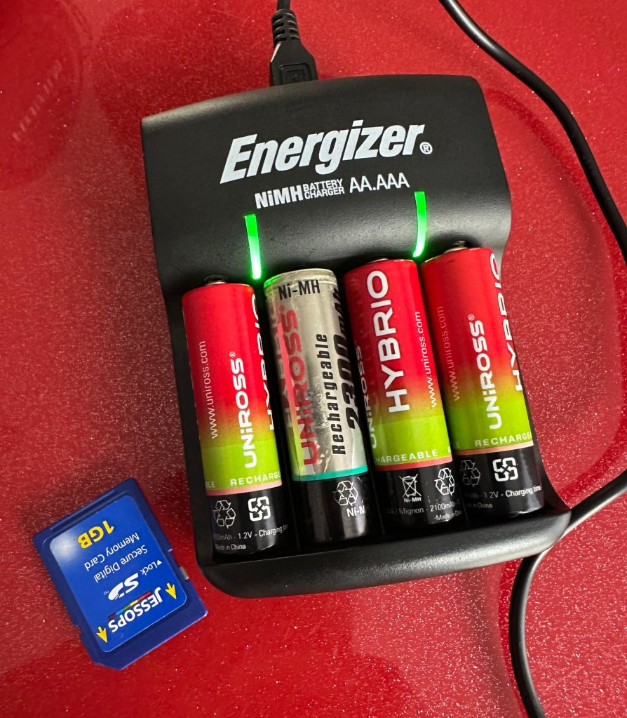
A little bonus was that there was a 1Gb SD card in the memory slot that works. There were also 4 rechargeable batteries in the camera that after a while on my charger, have fully recharged, and this makes the deal an even better one and quite a bargain to be honest with you.
Repair:
I’ve tested all systems, menus and functions on this camera and there really is nothing else wrong with it. It’s far too good to be used as a spares camera and deserves to be repaired.
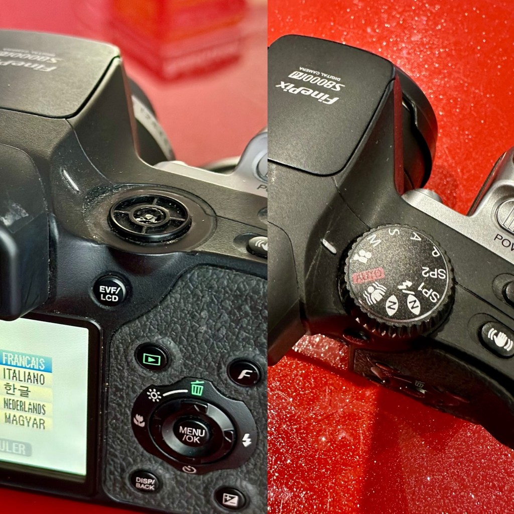
Missing mode selector dial
I have two options here, either buy the mode selector dial on its own from our friends in China, or buy another donor camera in a far worse state and available for about the same price as getting the dial from China. I just have to wait for that donor camera to first become available. I’ll give it a couple of weeks and if nothing comes up then China it is.
In preparation for whatever route I decide to take, I’ve decided to do some prep on the old camera and get the old selector dial mechanism taken out ready for the new dial to be put in place.
I’ve dismantled the camera unit to be able to access what is left of the mode dial switch.
Back is off Switch unit and ribbon cableSwitch removed It’s basically a two piece potentiometer type setup
This wasn’t too awkward to dismantle, half a dozen screws and a small plastic prise tool was all that was required to reach this point. There was some protectorate covering the metal frame of the switch housing that was contained by four tiny screws. Once this was loosened the housing came away and I was able to remove what was left of the old mode dial that had originally been in place. There wasn’t a lot left.
Remains of previous dial
The camera now sits in this position of being dismantled whilst I source a new dial to replace. As stated I have two options of buying a new dial either from China, or by getting a damaged camera as a spares source, and I’m currently looking at the latter as this could be purchased for about the same price as the dial from China, and would allow me a few more spares.
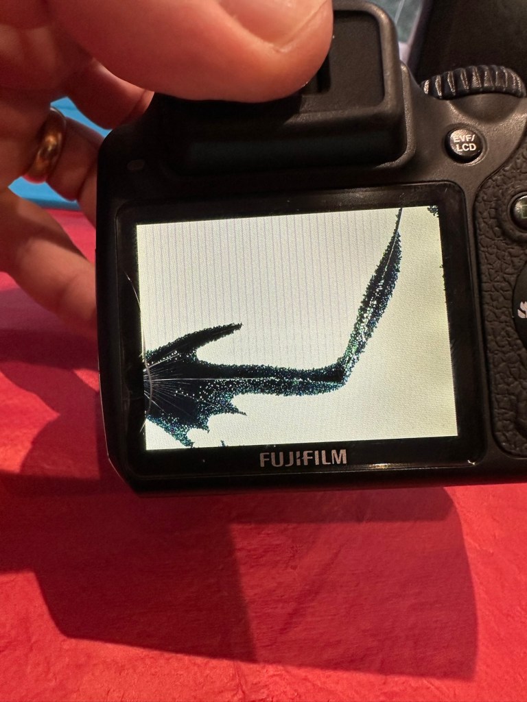
I’ve purchased another unit as a donor. The unit in question has a damaged LCD screen. I’m going to use that camera as a donor for the mode dial I require.
The donor camera has arrived. And to be honest it looks ok. It has been dropped at some time as the lens has a scratch on it, and the Rear LCD screen is damaged. That’s about it.
A good looking donor camera, the only issue being the damaged LCD screen
I’ve taken some pictures with this unit and the camera is working fine, as you can still view pictures you have taken through the viewfinder. It works ok, but I need this mode switch to fix another camera, so i’ll probably just use what remains as spare parts due to that scratch on the lens.
Let’s get the donor camera disassembled to harvest that mode switch.
There are only about six screws to get the back of the camera taken from the body, you just have to be careful not to damage the ribbon cable that is connected to the mode dial assembly that we are going to use today.
The two cameras, and the mode dial assembly we need to fix the original camera
I did all the disassembly of the original camera to save time, and it took about 5 minutes to get the donor camera stripped down. Once inside there is some insulating material covering the switch assembly, this has to be removed but cannot be reused as it has lost its adhesion. When reassembled I have used electrical Kapton tape to replace the original insulation. This has worked just fine.
New Kapton tape insulation
Assembly involves checking that the button settings relate to the markings on the camera body, this is important at this stage as the last thing you want to do is reassemble the camera to find out that you have the dial in the wrong setup. Do it now and save time and reduce the possibility of damaging the connectors and body clips.
Before and after
Result:
We have a beautifully restored and working and fully functional bridge camera that takes good snapshot photos. It’s not high end, it’s very much a learner camera but good at documenting what’s going on around you. Its mode dial that was missing is now working fine. A little polish and it has come up looking lovely cosmetically. it’s a good little unit.
The camera has come up lovely and is now complete and fully operational
Here are a selection of snapshots from around the home just to prove it’s working as it should. Nothing special, it just does what it was always built to do. Take snap shots.
It works. I’m happy. And another camera has been saved from landfill.
Thank you for passing by, as always it’s most appreciated.
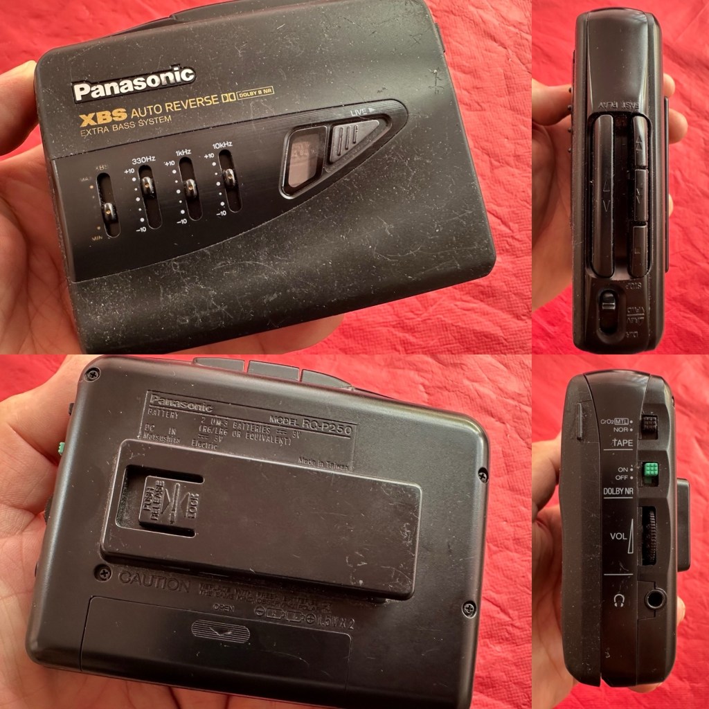
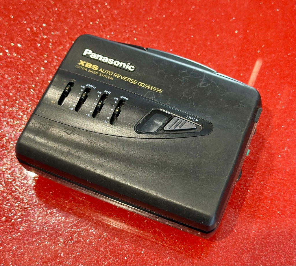
At a family gathering this weekend, an elderly family member approached me and asked if I could take a look at his Panasonic personal tape player, and maybe get it back up and working.
Who am I, to turn down such an invitation, so I took it on and promised him I’d have a look into it. There is, “No rush“ I was told. Just as well, as it’s busy in every aspect of my life at the moment.
Here’s the spec:
Type: Auto Reverse Cassette Player
Tape Type: type I, CrO2, Metal
Output: 20mW
Battery: 2 x AA
Power Supply: RP-AC33 (3V DC)
Dimensions: 114.2 x 84.4 x 33.1mm
Weight: 156g
Finish: black
Year: 1993
Hifiengine
Panasonic RQ-P250
Assessment:
It’s well used, and has always been and if I can get it working, will continue to be so. At the grand old age of 79 my brother in law is not about to change his ways and is quite comfortable listening to his old Cassette collection whilst out and about, on trains quite a bit of the time, as he travels up and down the country. He’s a lovely old fashioned set in his ways guy and we wouldn’t have him any other way. It would be blooming lovely to get this back to him working again.
It’s scarred, been well used but looked after, apparently it’s gone from playing quite well, to slowing down and dying completely. I think I know what the issue is but I’m not going to curse myself by saying I know what is wrong, when it actually turns out to be something totally different.
On the Beach – Chris Rea
And I love his choice of music. Let’s get this repair underway so we can listen to Mr. Rea in a lovely crisp sounding manner befitting of an 80s rock star.
Repair:
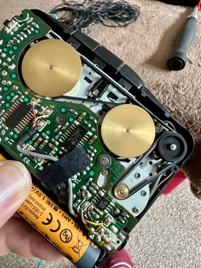
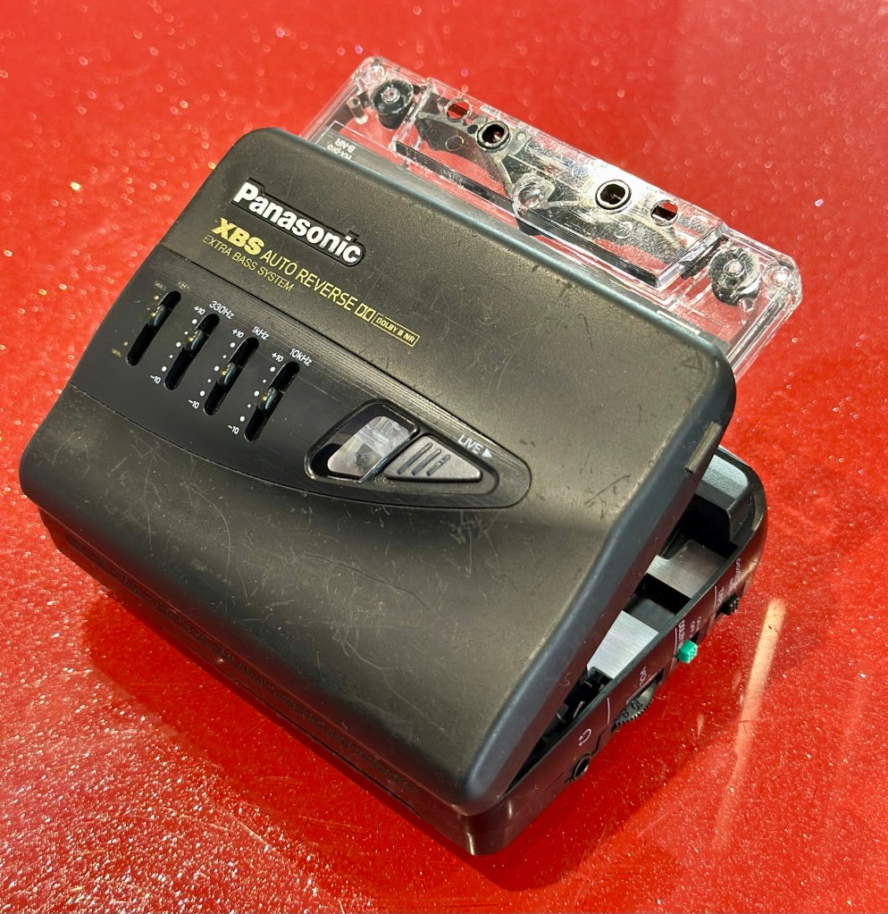
Batteries in place, earphones connected, push play. No movement from the capstans, and even when put in forward and reverse there is no movement from either capstan. I can hear all the electrical noises such as the tape head picking, and I suspect at the grand old age of 32 years old that the drive belts have probably given in. Let’s open it up and have a look.
And just as I thought. Two drive belts in here, they are both loose, one though is so loose that it has wrapped itself around the two capstans, no wonder it wouldn’t start up.
Two drive belts visible, both so stretched that they have ceased working
I have plenty of these belts spare, I just had to sort out the two closest matching in size. Too slack and you introduce warble, too tight and it will be off speed, you need to get it just right. Adjustments can be made to the motor speed but this will only come back to bite you once the belts wear in.
New belts in placeOld slackened belts
I’ve put two new belts in place, and at some frequencies there is a little wobble, but with Dolby switched in place this can be removed digitally, this will settle over the coming weeks after more use.
I have used some silicon grease on the cogs, I have put contact spray in the motor and the volume controls, and used IPA to clean all the tape contacts and capstan wheels and posts, it’s basically been given a little service to see it forward for a while longer.
Body now reassembled, new batteries put in place, it’s time to test it.
Result:
A quick polish, to tidy up, won’t get rid of the deep scuffs, just makes it a little more presentable. Cassette inserted, headphones plugged in and as expected it’s working just fine, we can hear Mr.Rea in all his gravel voiced glory. So can you, in this video snippet below, that hopefully won’t get a copyright strike 🤞
🎶 On the beach 🎵
So there we have it. Another item brought back to life with about 30 minutes work. It’s going to make someone’s day, and I’m as pleased as punch that I could play a part in contributing to that.
Working well, looking ok after a quick service and some TLC
There you go. Hope you enjoyed this quick fix.
Many thanks for passing by. Always most appreciated.
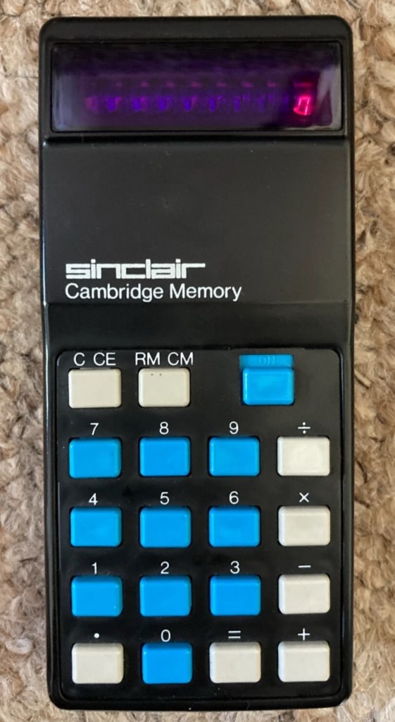
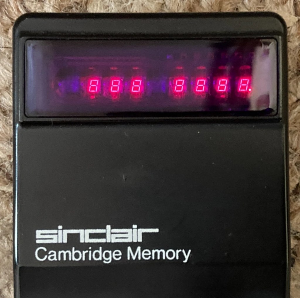
This auction is for a used cased Sinclair Cambridge Memory pocket calculator and original case. The item is in very good cosmetic condition as is the case which still has its instruction sheet. The item is powered with 4 x AAA batteries (not supplied) and does work although 1 of the digits is faulty and does not display (see pictures) plus the number 5 digit is not working. Please refer to the pictures and description provided before bidding.
EBay
It’s faulty…obviously
So it does work, but it doesn’t? This calculator is a model one memory calculator, that dates from around July 1973, ( Actually May 1975 see photos below) and is one of the earliest available mass produced electronic calculators available in the UK at the time. And it was produced in collaboration with a guy called (Sir) Clive Sinclair, who in the following decade would become synonymous with tech development in the UK. It retailed at £29:95GBP, and given the rate of inflation, its cost today in 2025 would be a staggering £463GBP. Wow!
Courtesy of Vintagecalculators.com
I love collecting old calculators, I couldn’t afford one back in the day when they arrived on the scene as I was only a child and probably only on about 20 pence a week pocket money, and savings and investments were not even known to me at this period of my life. The thought of saving that precious 20p a week for the next 150 weeks wouldn’t have even remotely crossed my mind. What no sweeties?
But I can buy them now, so no big issue!
So this one has become available, and I’ve been tracking it for a week or so, there were nine other people watching but I secured it for a total including postage of £14:49GBP, and I’m happy with that, it’s a piece of retro history for a very good price. Even if it remains faulty, or should I say working but not working?
This unit obviously has its problems, the button number 5 doesn’t work and one of the led digits is also not functioning. Hopefully I can get these issues sorted and soon have the calculator back up and working as it should. That would be nice. I’m looking forward to this little project.
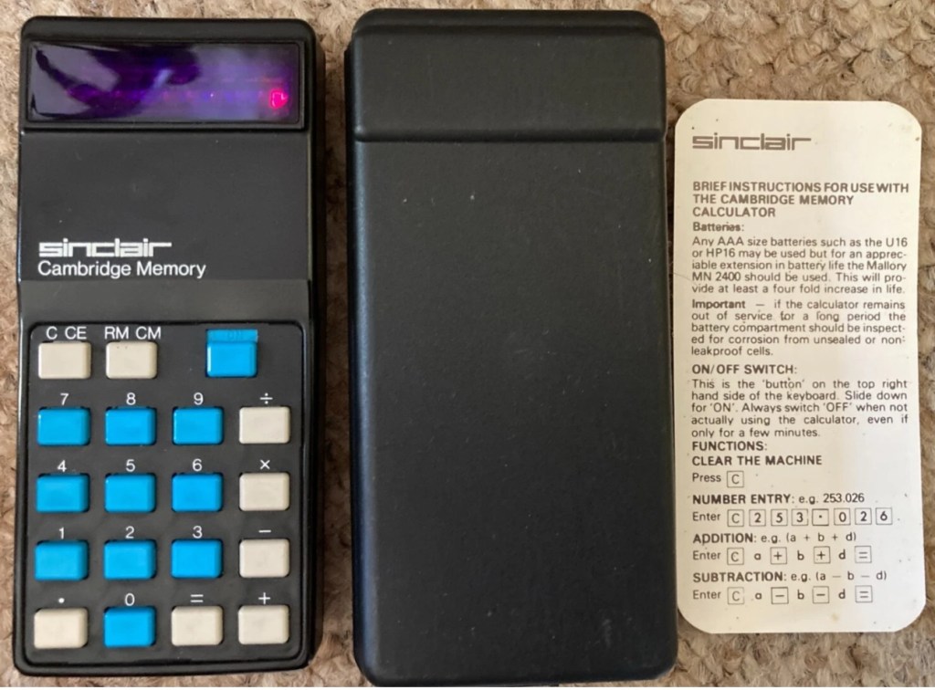
Assessment:
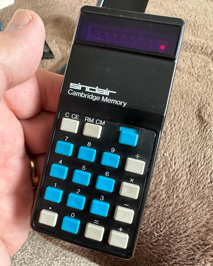
It’s arrived and it’s a lot smaller than I anticipated. It has a separate hard protective case, which is a nice touch and a small info sheet on its operation. Cosmetically it’s in a good condition with just minor signs that are age related. There are no gouges or scars so it has been treated well, though it’s not pristine.
Two buttons unresponsive and one LED
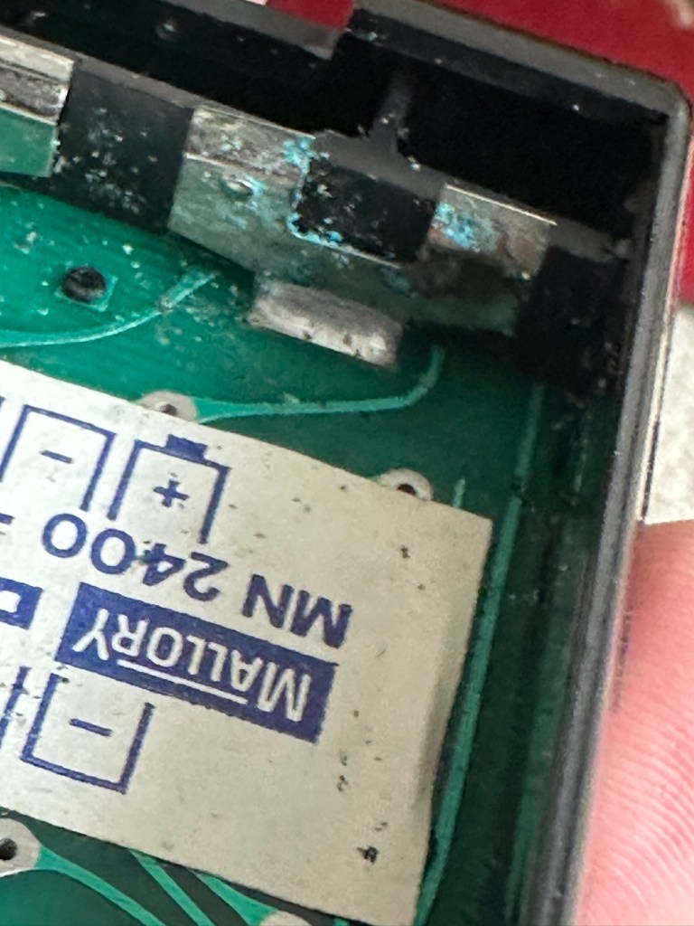
Batteries go in ok but, I believe old style AAA batteries were a little wider than those used today and would sit a bit more snuggly in the battery compartment. As you can see there is a little wriggle room here, and springs at both ends need adjusting to help prevent this. I may have to use some spacers so the batteries sit tighter in place.
Gaps between batteries – means movement
The switch is a bit temperamental and can be seen quite plainly from the battery compartment. It looks strangely out of place with no batteries in place.
Switch offSwitch on
It is such a basic design solely relying on tension of a small metal plate to short across the connection points. Should be a simple enough issue to sort.
There is a little battery contamination on one of the battery contacts, again this shouldn’t be too much of an issue and should clean up ok with some IPA.
Some battery contamination
It was originally reported that there was one unresponsive button this being the number “5”, there is also another unresponsive button, the multiplication “X” button. There is also one LED indicator, the 4th one in from the left hand side that is not operating. Add to this the issue with the On/Off switch and the contamination, and the original faults reported in the original sales pitch have now doubled. I just wish people would spend more time going over the issues and then give actual accurate feedback as to what the real faults are, it would make for a far more pleasant buying experience. Rant over.
There doesn’t seem to be a single screw holding the body together, I just hope it isn’t all heat welded.
Let’s try to get inside.
Repair:
Well it cracked open quite nicely with no issues with just a plastic flat prise tool. The main board just sat comfortably in the unit, secure, and not a screw in sight. Strange as time moves on some of the games units I come across have best part of fifty of the little blighters to remove before you get anywhere. sometimes the old way is good.
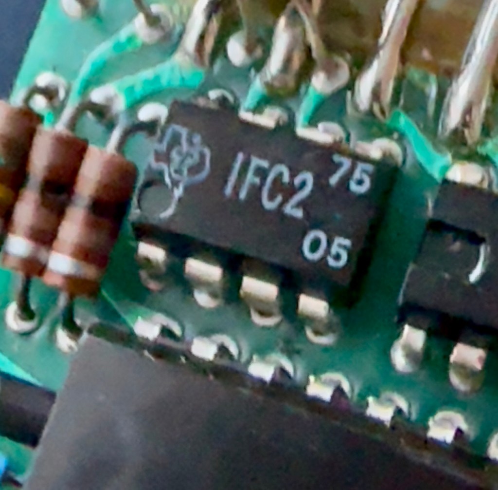
Bare boardOpposite side of boardDate is May 1975
The dismantling of the keyboard is a little complex and you have to take time and make sure you know how it’s going to go back together, it’s just a bit fiddly. The board is quite straightforward and as soon as I see some of the IC’s it dates the unit perfectly. The chips are dated May 1975, and that is about 18 months younger than what I originally thought, it’s quite informative to get inside and learn occasionally and this is just as good as having a birth certificate presented to you. All good stuff.
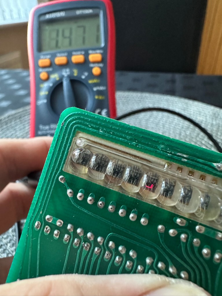
I’ve proved that there isn’t a problem with the missing digit on the display as using my multimeter in diode mode I am able to prove that this LED is working fine.
LED working
The picture shows just one part of the display range on this particular digit, I can assure you all other sections of the display are also working.
Regarding the case with the buttons not working. I have checked this out for continuity and both digits go through the same portion of the main IC and there doesn’t appear to be any broken traces. It’s a strange one but I have also found some really poor solder joints that are either cold joints or just poorly soldered from the start, there are a couple of resistors that need re soldering. It may be nothing at all, but it needs attention, a full reflow wouldn’t go amiss or take too much time.
Faulty resistor joint
I’ve reflowed the entire board due to there being a few cold solder joints.
Full reflow completed
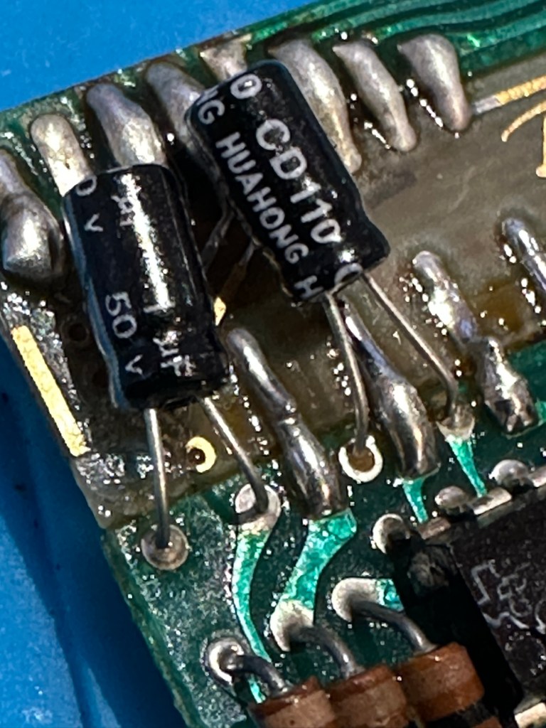
On top of this I have taken off two old capacitors and tested them out of circuit, and both were out of their operable range of +/- 10%. As a result of this I have replaced the offending components with comparable new ones.
Old capacitorsNew capacitors
Even with all these extra tasks being undertaken there is absolutely no change in the way it operates. Nothing has gotten worse, the faults that were originally there still remain. I have done some research on line and carried out some further tests and checked expected voltages, most are within range except one that appears to be less than its expected value. After testing everything on this board, every component I can only surmise that one of the three chips has failed, I suspect very much that this, the main chip, a CZL550 integrated circuit. Otherwise known as “Calculator on a chip” is the one that is at fault.
A CZL550 chip
To be quite honest these chips are fairly rare and command a price far in excess of what I paid for the original unit, and I don’t really want to do that. I think I’ll wait around to see if I can secure another faulty unit to complete this repair, so in the meantime, and until I can secure such a unit I will put this repair on hold.
Result:
Well, it’s not what I wanted but sometimes you just can’t win with some of these old projects. In no way am I walking away from it, it’s just that the parts are so difficult to get hold of that you really do have to just wait until a sufficiently faulty one comes up for sale. And that could be days, it could be weeks or months. So for now i admit defeat, but it will not be going to trash. It will remain in my ever expanding “To do” box, for me to pick up on at a later date. And when I am in a position to move this project on, I’ll pick it up in a continuation of this post.
Many thanks for passing by. It’s always appreciated.


You must be logged in to post a comment.