Not one to give up on a project I have looked at a suitable donor camera and believe I have found one as detailed below. Only difference is that I had to buy two cameras as they came as a bundle. Not a problem as I can always do a separate post on the other one, the two have cost me a total of £15:00GBP bartered down from the original price of £30:00GBP. A bargain! So let’s just call it £7:50GBP per camera.
What the listing stated:
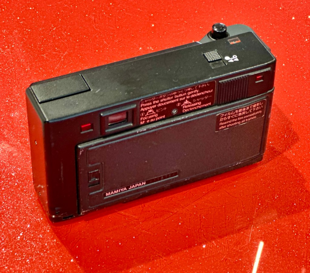
mamiya shutter button is stuck. red light on the right comes on. some external corrosion pictured
ricoh no power at all
EBay
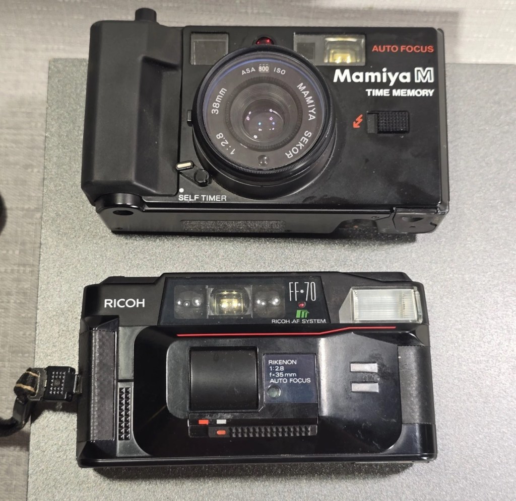
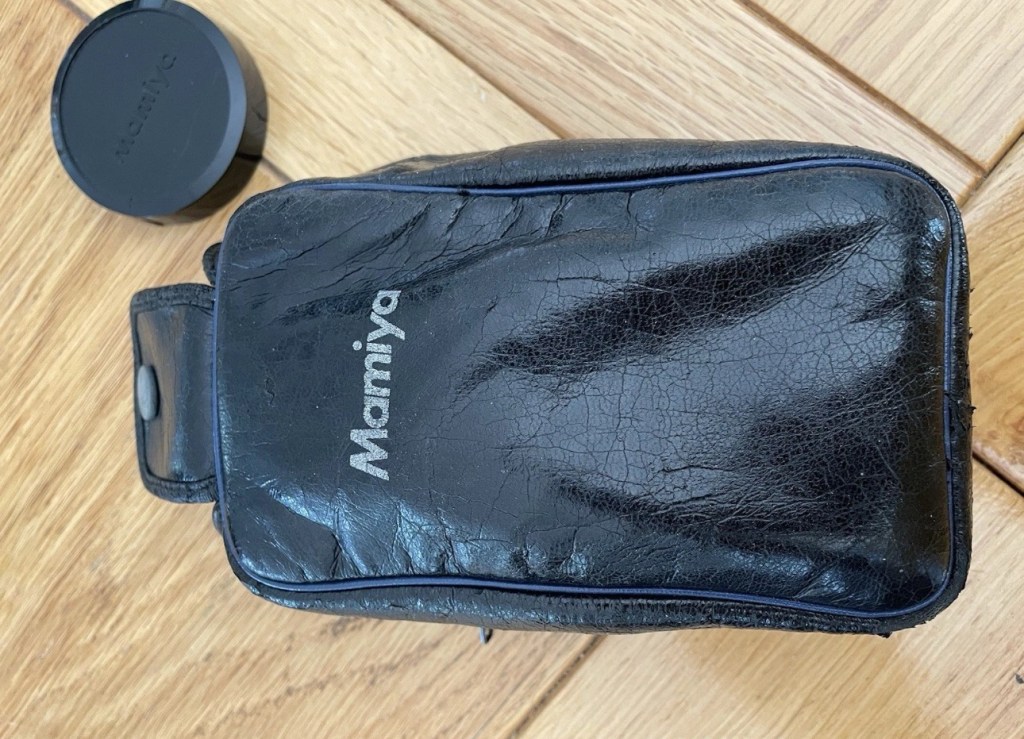
The two cameras
Assessment:
The Mamiya is in quite a poor state, and is the Time Memory version that differs very slightly from the version I originally worked on, it’s essentially the same camera as the Mamiya M, but with an added quartz dating mechanism for imprinting time and date information on the film. This model was the last 35mm camera Mamiya produced before focusing solely on medium format. However the back seems to be a bit rusty whereas mine is in excellent condition, so I will be using a mix of the two units to make the one good one.
Repair:
The Mamiya looks good cosmetically until you open the rear and see the rust around the door, not a problem as I won’t be using this part of the camera. The red light does not come on at all and the shutter button is stuck, that’s for sure. The whole camera is dead.
Let’s get into it.
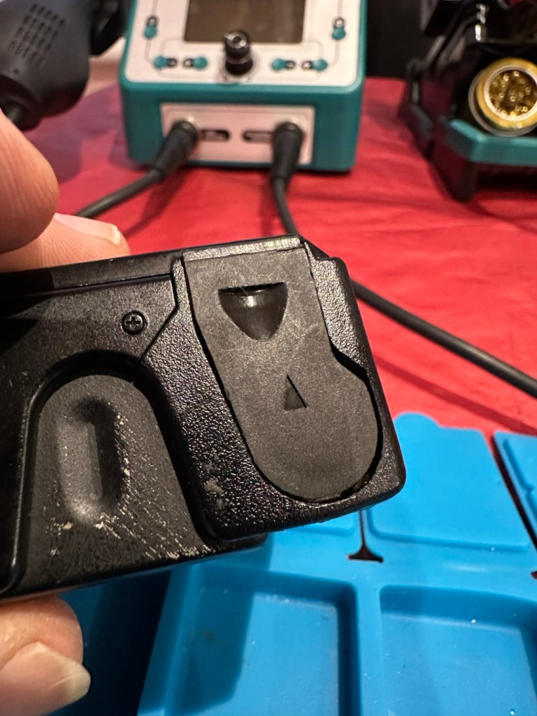
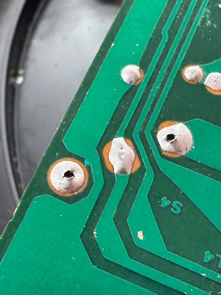
Once opened all looks ok so I decide to have a search around with the multimeter checking the basic operation. Am I getting 3 volts at the top of the battery barrel? No I’m not. It appears that one of the traces on the positive side of the power input board has lost continuity. For some reason the traces has been damaged, this could be either from corrosion or rubbing on something. The area affected is in the photo with the red ring around it.
The board top rightArea of no continuity
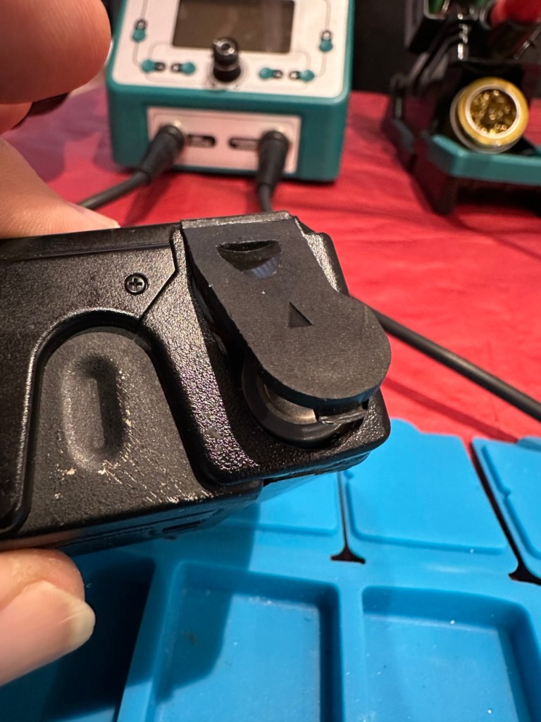
I’ve fixed this immediately using some solder to bridge the gap, I have checked continuity and all seems ok. I put some batteries in and the motor squeals like a banshee and then stops. You can hear the screaming motor below in the short video from its first screaming session through to its proper 80s sounding drone.
The screaming motor through to its repair
I don’t think this motor has run for years and it does not run consistently. I have sprayed it with some contact cleaner and let it soak. I have left it overnight and checked the operation in the morning and it seems to have improved.
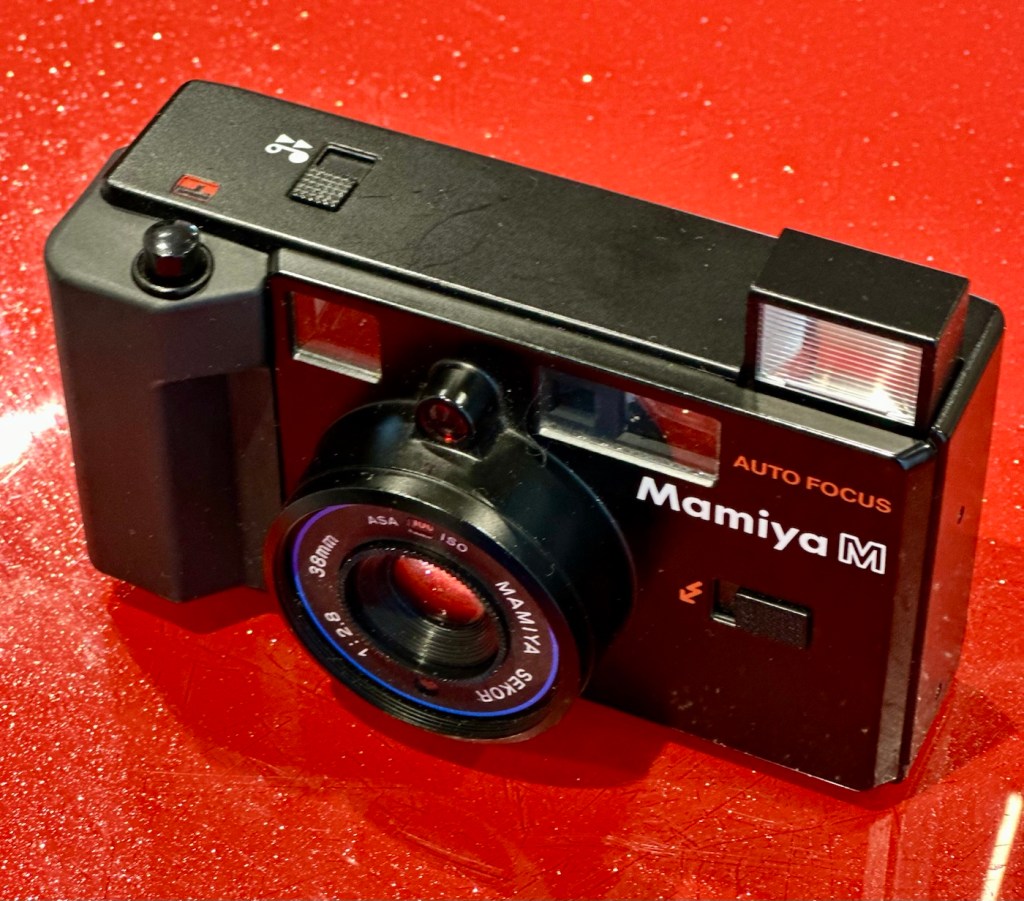
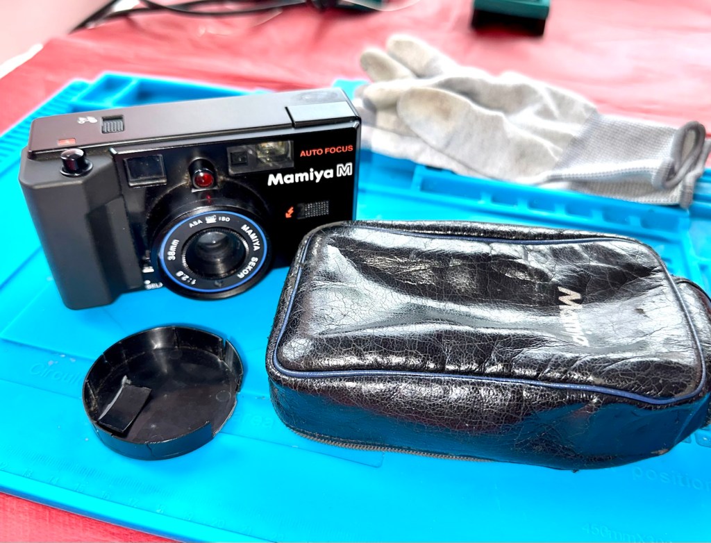
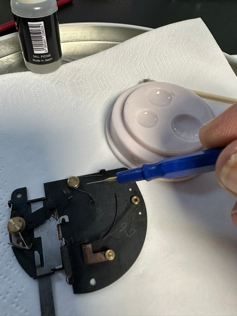
I’ve used the original fascia, rear door, focussing beam and flash capacitor from the first failed unit, and apart from a few bits of soldering, plenty of contact cleaner and some silicone grease, I’ve revitalised a failing motor and it is now working as it should. I forgot to mention I used some graphite on the shutter leafs to “lubricate” them. All optics cleaned and camera has been tested without film and is working just fine.
View finder indications are good with light meter operational, motor rewind works, flash and exposure is fine, and the motor advances as well.
Result:
I’m really pleased with this little camera and am pleased I didn’t give up on it. It’s taken two broken cameras to make one good one, and I have a good few spare parts left over to be used at a later date.
Re assembly taking place
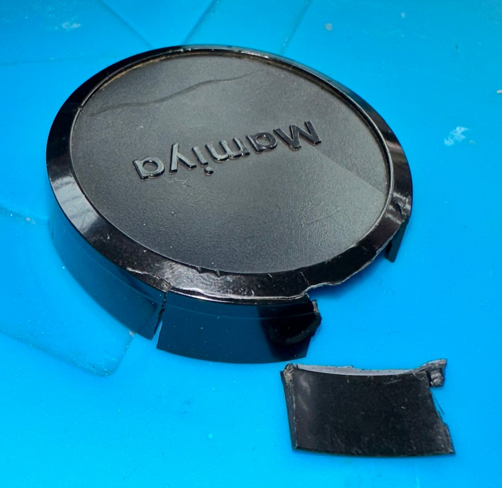
The unit looks so smart, the only real issue is the battery door that is notoriously flimsy and lots of references to its poor design can be found on line. A temporary way around this is just to put some tape across it to keep it closed.
That flimsy battery door
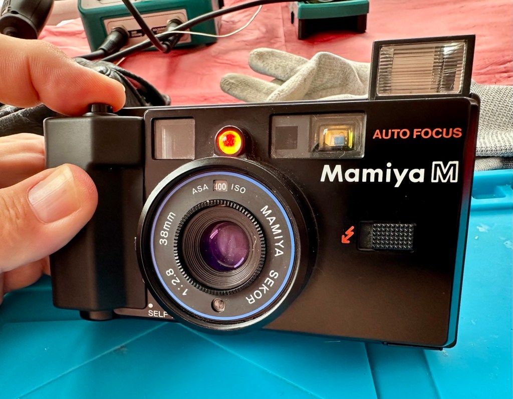
Beyond that issue, the camera is a really good looking unit that has cleaned up really well.
The completed camera
I can’t wait to run some film through it to see how it performs. I have a few cameras like this to test so I’m looking for some decent priced film to use, as i do need quite a bit.
As soon as I have some photographs availability I will link to this post accordingly.
Many thanks for following the repair, it’s always very much appreciated.
I’ve been after a couple of cameras for quite a while now that hold a great deal of sentimental meaning to me. This will become apparent when i publish the individual posts for them, but for now i just want to share the result of an auction i participated in on the 31st July 2025.
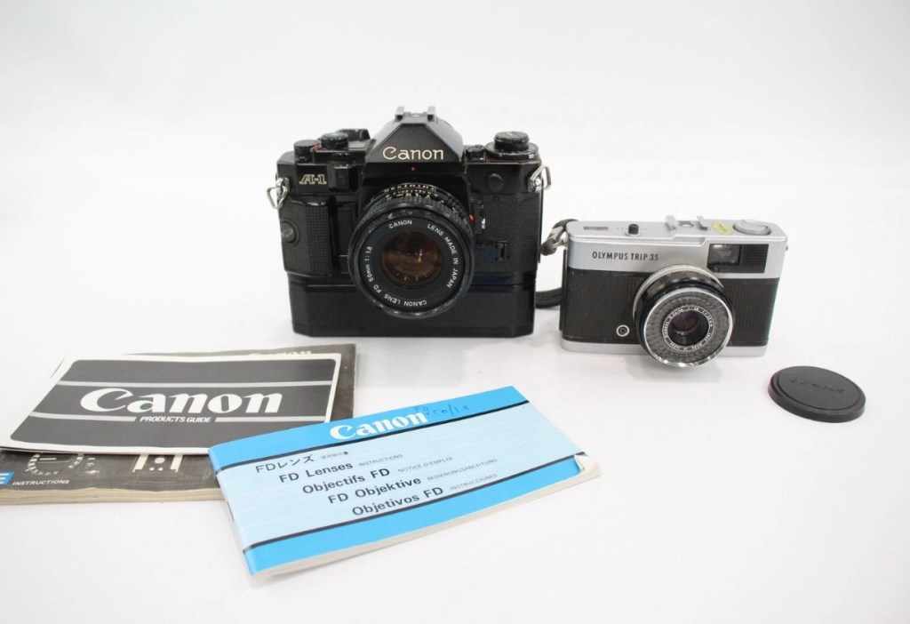
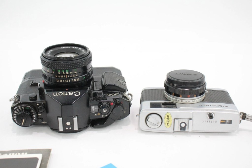
A Canon A1 and an Olympus trip
Today I’ve probably made the best purchase off of an auction site that I have ever made previous. I’ve been following a number of Canon A1s lately and they have all been going in the £120+GBP bracket, some even higher than that. Today I have lost out on two that sold for £93 for a damaged body and one for £121 that was just a body but of a much better quality. This particular auction I was watching was for an untested duo of cameras, a Canon A1 as well as an Olympus Trip 35mm. The Olympus alone normally commands the high £80GBP range and both of these were in this particular auction. I was just watching as this was going to sky rocket in my opinion, two good cameras from a respected seller who I have used before. Two minutes from the auction end, bidding was sat at £39GBP and I thought that any second now the price was going to go crazy, especially in the last 30 seconds. I put in a max bid of £55GBP for the lot, as I pretty much knew it would sail past that amount and go for a price in the £150-£200 price range. I hit the bid button with 20 seconds left on the auction….
You have won – congratulations!
I thought you’re having a laugh, no way. And then it came up with the winning bid being £39:00GBP no one else was bidding, crazy.
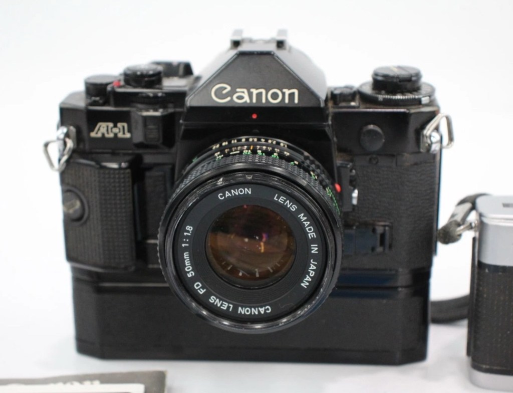
The A1 camera consists of the body, a winder, an FD 50 1:1.8 lens, a camera manual as well as a lens manual.
Postage was the grand total of £4:99 so my total for these two cameras was £43:99GBP. That is nuts, and to say I’m pleased about this is the understatement of the century. I have two of the cameras I wish for the most, and I have just landed the bargain of the day, I was in the right place at the right time. Wow. It’s unusual to catch other auction bidders sleeping, it will probably never happen again for me, it’s a very rare occurrence. Two cameras of this magnitude for £22:00GBP each! That’s unheard of.
I don’t know for what reason they are not working, as they both appear to be quite tidy examples. I have used this seller before and the posting above could also be worded such as to imply that the units may well not have been tested. But, that’s what this site is about, repairing old cameras and getting them working again. There’s no fun in talking about a good functional camera, that’s boring. We want the meat and potatoes as they say, we want to see things being fixed, or broken further….you never know with me.
Thanks for sharing my excitement at this purchase. It will all make sense once i’ve assessed the cameras and carried out any repairs.
Thank you for passing by. It’s always appreciated.
Anyone who has had an 80s/90s/00s camera through their hands would have experienced this at some point. During this time period many if not all camera manufacturers went through the phase of putting rubber hand grips on their cameras. Aesthetically pleasing, and ensuring a good grip of your new “Expensive” toy. I guess, they thought they had got it right. But as with all these good ideas they often come back and bite you right on the bum at a later date.
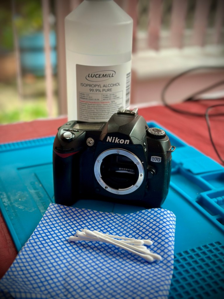
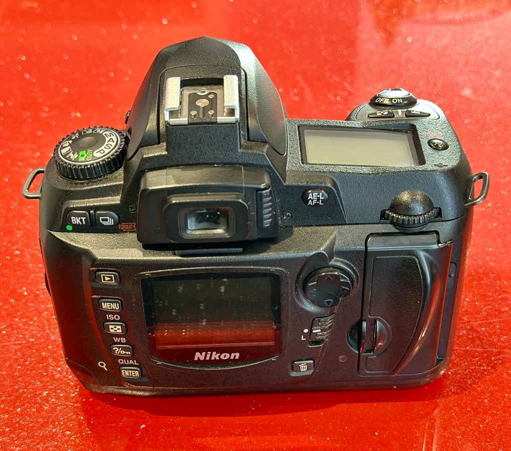
My particularly sticky Nikon D70
Ok there were probably no recalls regarding this issue, it’s just affected the price of these goods on the second hand after market, and more than likely a perfectly good unit has most probably gone to landfill for no other reason than “Feeling sticky”
Let’s look into the reasons why this occurs.
It’s pretty much down to a process called Vulcanisation. Vulcanisation is a chemical process that hardens rubber by cross-linking polymer chains, making it more durable and elastic. This process, often using sulfur, heat, and other additives, transforms natural or synthetic rubber into a material with improved properties like resistance to heat, cold, and deformation.
However after many years, the process begins to break down, this causes the rubber to become sticky and in some cases the rubber just breaks down causing traces of rubber dust all over the place. Add to that the normal oils from fingers and palms and the stickiness then becomes highly noticeable, and makes for a very unpleasant experience.
We can’t stop the progress of the degradation, we can however do something about the sticky state, maintain good quality and make the use of the item as pleasurable an experience, just as it was when first purchased. Many believe the stickiness is down to the way the item is stored, and it not being used on a regular basis, as there is plenty of evidence out there of similar aged cameras not suffering from the issue at all, as they are used daily, namely by professional types where these cameras are tools of their trade.
It involves some work, and patience. I am writing this post as I have 8 cameras that i am currently working on, all Nikon D70/D70S and they all have this problem, and they date from 2004.
A load of very sticky Nikons
I use a process that you will easily find on line, the most simple process and it involves using a substance called Isopropyl Alcohol, my one is 99% pure, (also known as rubbing alcohol) I don’t think the purity of 99% is essential but i use it as i have plenty of it around, what with all the circuit board work i do, and the cleaning they also require.
Some people have had results just using a dry cloth and no chemicals, patiently rubbing and rubbing, some for a few hours at a time, until all the mess is removed. If that’s the way you wish to go then fine, i haven’t got the time for all that, i’ll be talking you through the way i do it below, with a chemical.
My technique is simple, lint free cloth and some cotton buds are all that i use, along with a tissue wipe (Such as armoral, or a car cockpit cleaner solution with a dry cloth) and a cocktail stick to finish. The reason for the wipe will become clear at the end.
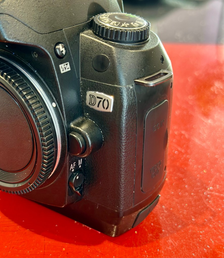
My Guinea pig for today is a Nikon D70 I have requiring repair. It is a particularly “Sticky” individual and will be a good candidate on how to deal with this sticky situation. This is the process I use on all my equipment that has rubber such as this as part of its structure. It’s worked for me for many years, some people say that it will need doing again after a short while, that’s never been the case for me, and there are a number of documented cases on line where six years after this treatment has been done, there is no repeat of the initial problem. The rubber remains good.
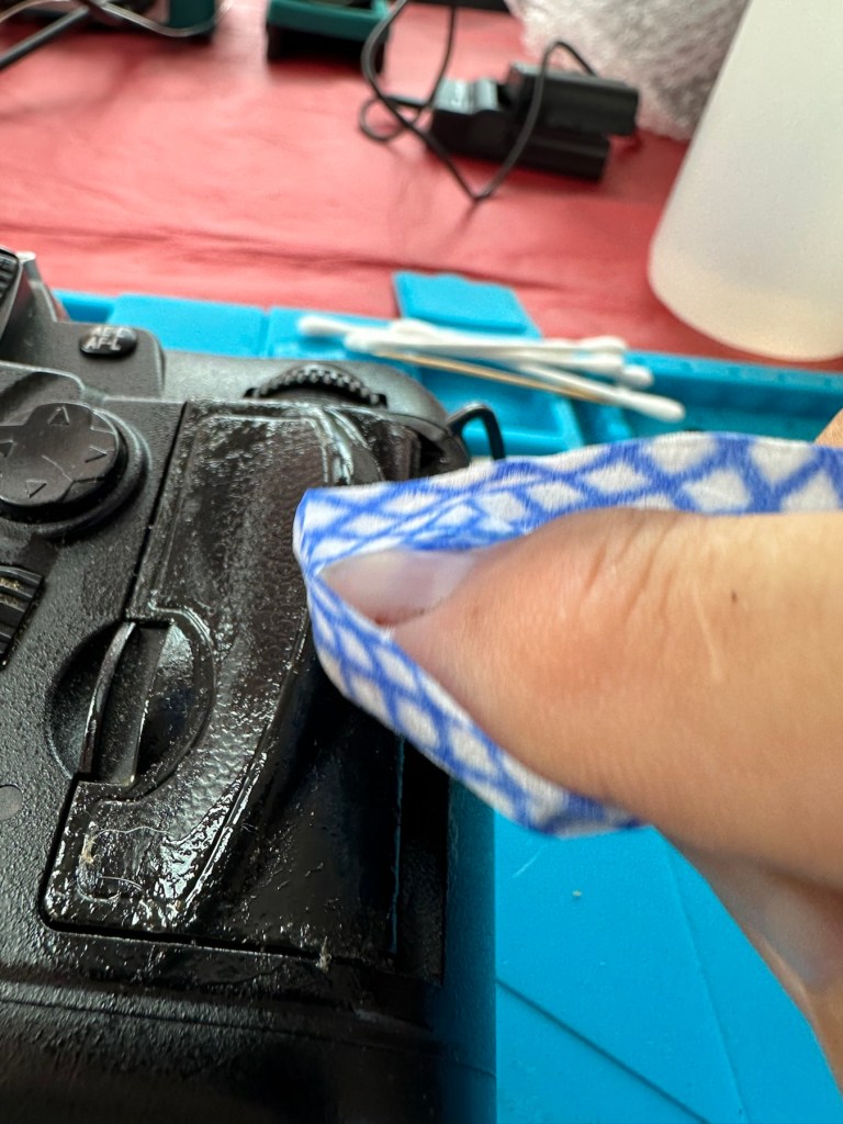
Using a small amount of IPA on a lint free cloth gently wipe the area of concern and you will see the stickiness start to lift, it looks like a glue.
A glue type deposit Gently wipe The dirt is soon lifted
Make your way around the whole camera paying particular attention to those really sticky areas. The IPA evaporates really quickly so you get to see results really quickly. If after one try the stickiness remains then try another application. A good indicator is that when you use a fresh part of the cloth, you see less dirt come off with each application. When you put an application on and come away with a clean cloth, your job is done.
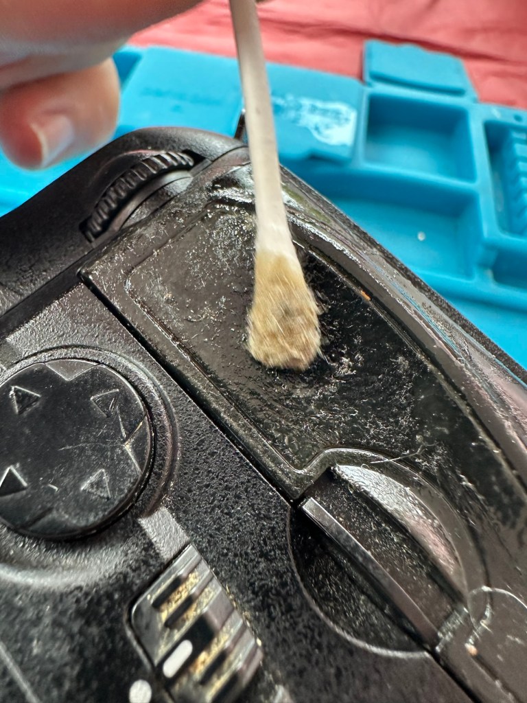
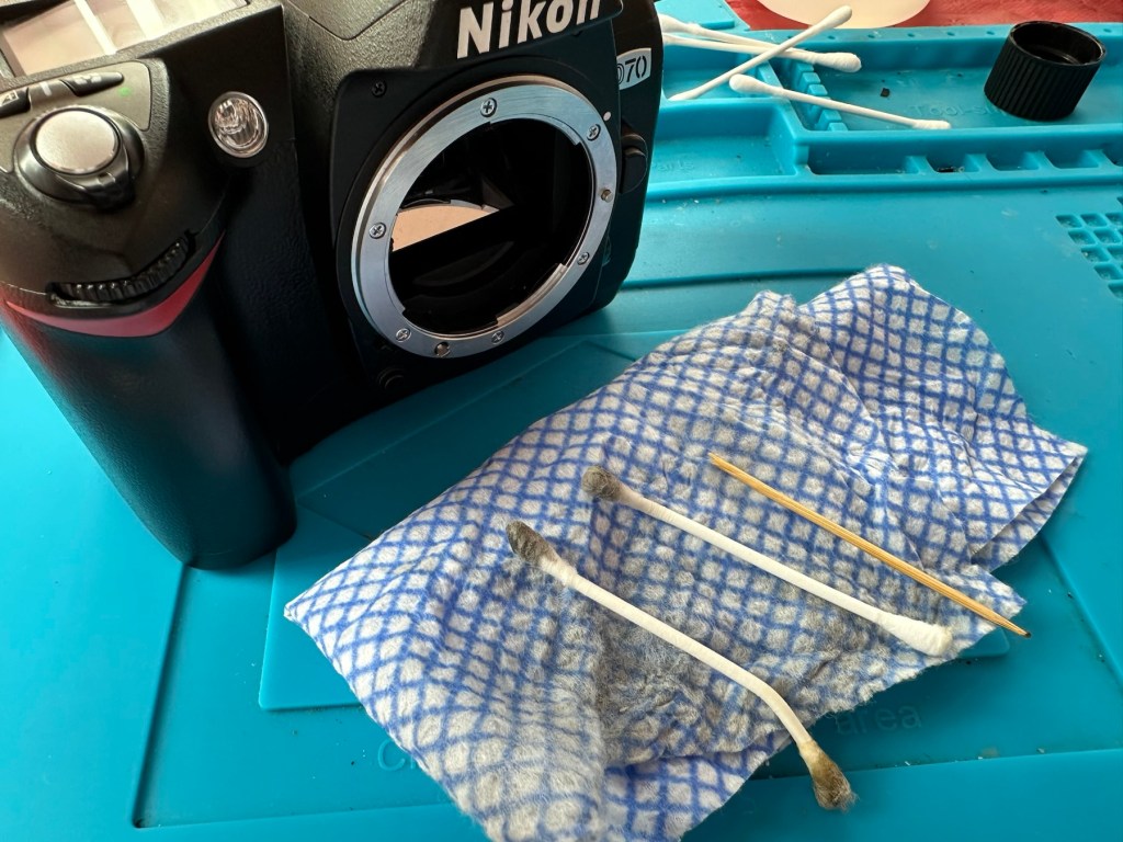
The cotton buds for the cornersSecond application The dirty cloth and cotton buds
The cotton buds are used for getting into those inaccessible crevices you can’t get into with the cloth. As before as they stay cleaner and pick up less dirt your work is done. All this cleaning and moving about of dirt sometimes transfers the dirt into creases and joins between the rubber and the camera body, this is what the cocktail stick is for, to get into those small gaps and scoop the dirt and debris out. Complete with a final application of IPA in this area and the dirty work is now done.
Now earlier I mentioned about using Amorall wipes or a car cockpit cleaner. Sometimes this process can dull rubber, as you have just removed the layer that was providing the gleaming glory back in the day. You can’t have it all your own way but a good quality interior dashboard cockpit cleaner really does add some shine and life to that old camera and really does do a good job of restoring it. I use Auto Glym interior shampoo on a lint free cloth and apply this by gently applying all over the exterior of the camera. It is now exceptionally clean. A quick rub over with a dry cloth once this is dried and what more can I say? This is a different camera, looks stunning and has lost all trace of stickiness and dirt. Now it has that extra layer of protection as well, it’s now a pleasure to behold.
The finishing touch.
This little task probably took just over 20 minutes to achieve and gives so much satisfaction to me as you can see a cameras appearance change in front of your very eyes, and anyone can do it. No camera deserves to go to landfill just because it has this sticky exterior, it’s simple to do and can revitalise an old and much loved camera.
The finished item – stickiness now a thing of the past
I hope this has helped with dealing with the stickiness issue, if you ever experience it. I have even heard reports that a good quality window cleaner can also give similar results, but I’ve never tried it, so there really is no excuse if you have a camera in your ownership needing similar attention.
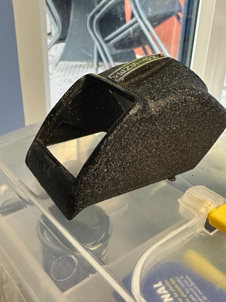
Mamiya M point and shoot camera. It’s in fantastic original condition and is cosmetically excellent with original case and lens cap included. The lens appears to be bright and clear from the front. HOWEVER…when batteries are inserted the shutter does not fire and I suspect it is jammed somewhere. The lights come on and it goes “click” but the aperture does not open, nor does the film winding do anything. For spares or repairs only, I’m sure somebody with the know how could get it up and running again. Priced super low as I want it shifted and can’t bring myself to bin it! No returns please
EBay
A well made 80s point and shoot 35mm camera
Here’s a little bit about it:
The Mamiya M is a 35mm autofocus compact from 1982. It has a boxy plastic shape, with a fixed Mamiya Sekor 38mm f/2.8 lens. The lens is four elements in three groups. Exposure is fully automatic, based on the film speed, where the ISO is selected via a dial around the lens. Film speed available is 25 – 800 ISO.
The metering cell is located just under the lens, but within the lens ring. This allows for the metering to take into account any 46mm filter screwed onto the lens. That is assuming it is not a graduated filter. Fastest shutter speed is 1/500thsecond with the slowest at 1/8th. The camera is always on, except when fitted with a specially designed lens cap, which triggers the off state. There is a strategically placed switch it pushes against on the right side of the lens. Most of these caps are lost, including mine.
Photothinking.com
I don’t know what attracted me to this camera, but the fact the seller just wanted rid of it at a cheap price was a starting point. It was advertised as £4:36 GBP and £2:45 delivery, a total of £6:81GBP. I bartered a bit and got it all in for £5:44GBP so I got it a little bit cheaper, a bargain if you like.
Mamiya has a great reputation for building high quality lenses. They were only in the 35mm autofocus point and shoot sector for a short while before immersing themselves totally into the medium format camera market. This 35mm camera was only in production for about a year or so, even though quite a few were produced, we are looking at the low hundreds of thousands, not the many millions, so the camera itself was not a major mass produced and marketed unit. It is a plastic preformed body unit. Known in polite society back in the day as “A plastic fantastic”.
If a Mamiya camera had a blue ring around the lens, specifically on its other models, it denoted a higher quality lens type, it was never confirmed this was the case with these small autofocus 35mm cameras, though many believe it is still the case. Photo quality with these little units was generally of a very high quality.
Lens caps with these cameras are very rare, this one has one and it is the original, and i suspect (from what I see in the picture) that there may be a small crack on the side of this one, but that is not an issue. This lens cap is integral to this cameras operation, as when it is placed over the lens, it turns off the camera, without it the camera remains live at all times, and would soon lose its power. It is an early power conserving device if you like. The camera looks to be in overall good condition, probably down to being stored in its original case.
You can view a lot more than I could ever tell you, just by watching this review by Mr.50mm that was posted earlier this year.
Excellent recent review
Since reading up a little on these cameras it appears that I may well have bagged a bargain, if it ever works. And I also believe the seller may well again be unaware of the operation of this camera and it may in fact be working just fine? Who knows? I have my suspicions but we will just have to wait until it gets here for assessment.
Below are some sale prices relative to this camera model that are currently selling on EBay, some extremely high prices compared to what I have paid today:
Current selling prices for this model
It’s plastic and so 80’s. And people obviously loved it. I’d like to be able to get this camera working again, and would love to run a roll of film through it to give it a test run. But first I have to assess it and see just what is wrong with it. I have a roll of old film available to test its “faulty” rewind system, and I have all my tools ready to crack it open and get inside, if I have to. So let’s get at it….
Assessment:
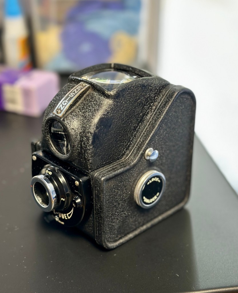
It’s arrived and I must say it is in an excellent cosmetic condition, probably down to being kept in its original Mamiya soft case. The lens cap I thought had a crack in, is actually broken, probably beyond reasonable repair, but at the moment that is not important. Let’s put that to one side for now.
Nice condition Lens cover damage
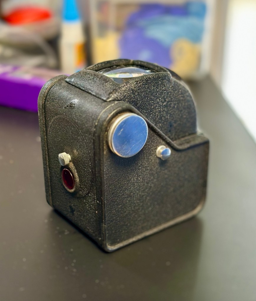
The actual camera is partially alive. When batteries are installed there is a red light that appears on the right rear side of the camera, this is the film transport light and should extinguish when transport is complete. The flash switch sticks a little, and when the flash is clicked into position the distance sensor light on the lens activates however the flash does not charge. The winding system is inoperative and does not auto wind at all. The shutter does not operate, despite the shutter leaves being able to move when gently coaxed.
Shutter not firingTransport light in top right cornerFocus light illuminates on front
There seems to be partial electricity throughout, this could very well be the issue. There just doesn’t seem to be a uniform continuity throughout the camera. This will need to be looked at. Something very weird is going on inside.
Repair:
I’m really annoyed, closer inspection shows there are 6 screws missing and someone has been inside this camera prior to me. Again I think I’ve been stung by the EBay curse of “Spares and repairs- no returns” will I ever learn?
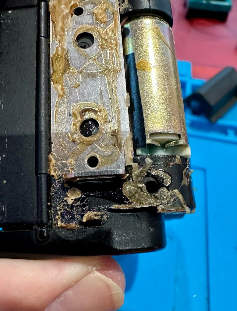
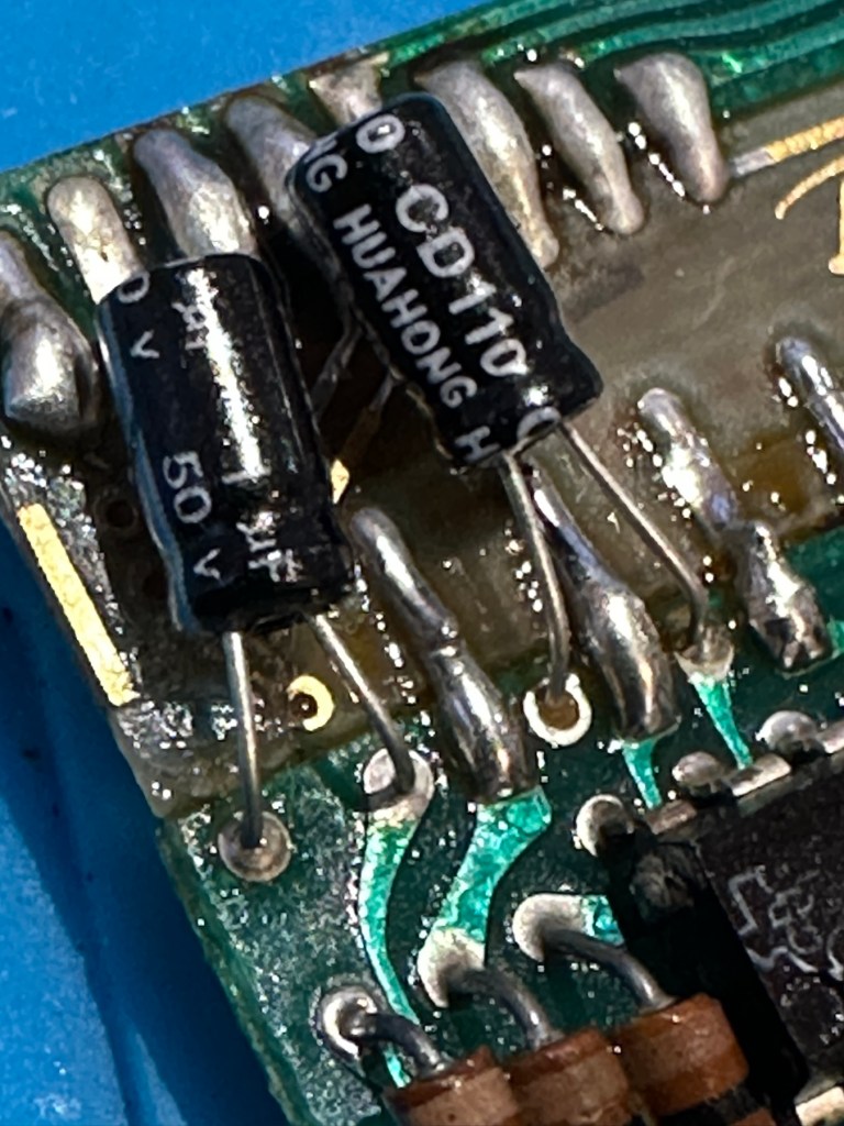
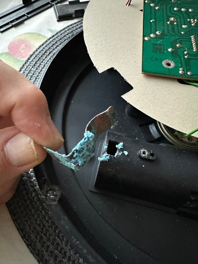
I’ve removed the remaining screws, and had to peel off the rubber grip to access and expose the motor and associated component board in this area. There will need to be a lot of cleaning here before gluing it all back in place.
That glueMotor exposed The grip gently peeled away
I’ve managed to get the flash charging light illuminated, and a current of 214v in the flash confirms that the Flash capacitor is holding a charge and more importantly, receiving a charge from the battery circuit. But I cannot get it to fire. There seems to be an issue with the shutter mechanism and the related electrical circuit in this area. The motor is not working, it’s either dead or not receiving power. I need to look in this area a little more thoroughly.
Front fascia removed
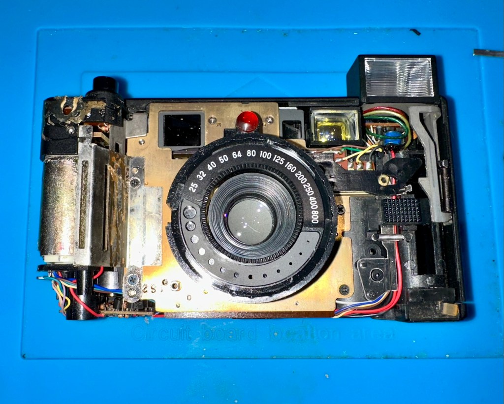
I’ve now removed the front fascia and now have a good view of the overall workings inside the camera.
Flash circuit board- tested okLens and leaf shutter removed
Ive taken out the lens and the leaf shutter, these seem ok and are working freely when operated. To me it looks as if the mechanism that triggers the leaf shutter is either seized or the variable capacitance system located at the top of the camera, that is basically just a needle on a circuit board connected to the focus light, could be at fault, it does not freely move on each camera actuation as it should, and this is not a readily available part.
That faulty part of the board
Misfiring- faulty
It seems the deeper I delve into this camera that I am finding more issues, and I’ve just found two parts that are incorrectly installed that are on a cog system connected to the motor. I’m fighting a losing battle as it appears the person who has been here before has probably added to the issues of this camera in their attempt to fix the original issue.
On top of the missing screws I’ve now found a missing capstan cog related to the leaf mechanism that would help explain a certain lack of movement in areas. The motor is dead, I’ve taken it out and used the bench power supply and it is non responsive. Even after spraying with some contact cleaning fluid and sitting there spinning the axis to get the solution absorbed, there is still no response. It’s totally dead and will require replacement.
Result:
Well. Once again I have been mislead by incorrect descriptions on the auction sites. It’s a shame really as this is a lovely camera and if it had not been tampered with inside, I’d probably be posting a different review today, one that would be more positive. With screws, cams and cogs missing I was pretty much set up to fail here.
Reassembled Back in its case
I’ve reassembled the camera and it is now back in its pouch. The positives are that I have learned a lot about how this camera operates, and just dismantling and reassembling the camera allows you to learn a lot about it, and the technology used during that period in time. All the screws that I removed have gone back into place with none leftover, yet another positive.
So it’s a failure I’m afraid, but it will be kept and either used as spares or I will obtain a suitable donor to get this one up and running, it will not be disposed of in any way. It will be reused. I’ve only paid a small amount for this, it’s worth it for the spares alone.
I have already set up a notification on the auction sites for when another suitable camera becomes available. I will update this post or post a new one that incorporates either the repair of this unit or its use as a spare parts donor, when that time comes.
ALL ITEMS IN THIS LISTING ARE FAULTY FAULTS MAY VARY BETWEENS ITEMS
SOLD AS IS
NO RETURNS
EBay
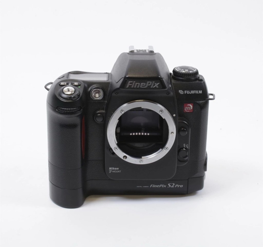
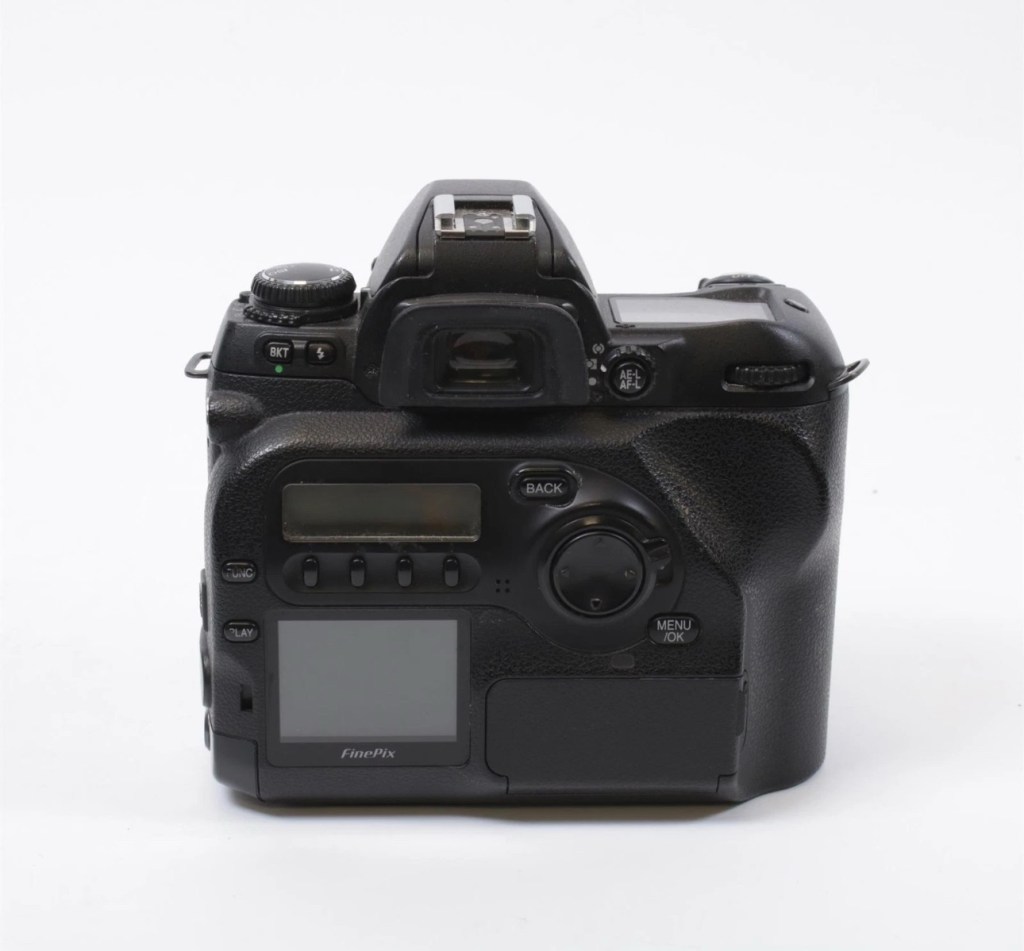
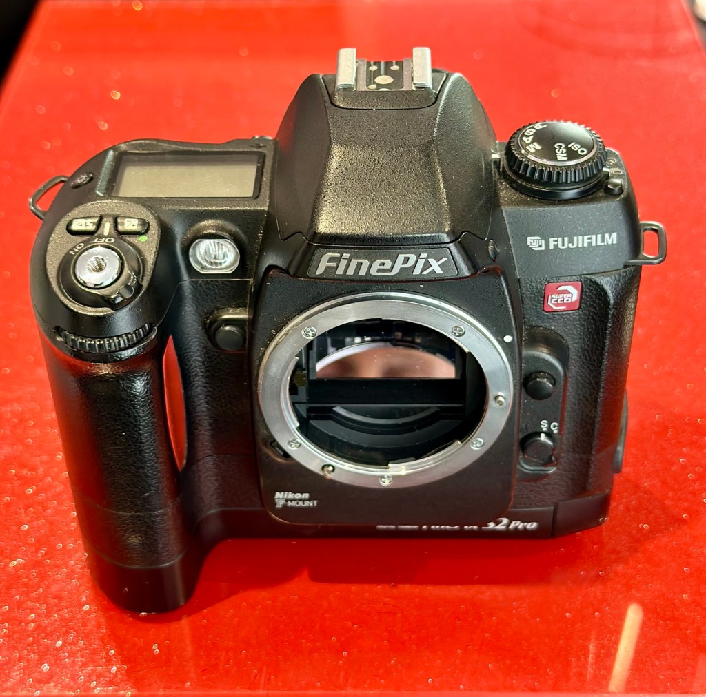
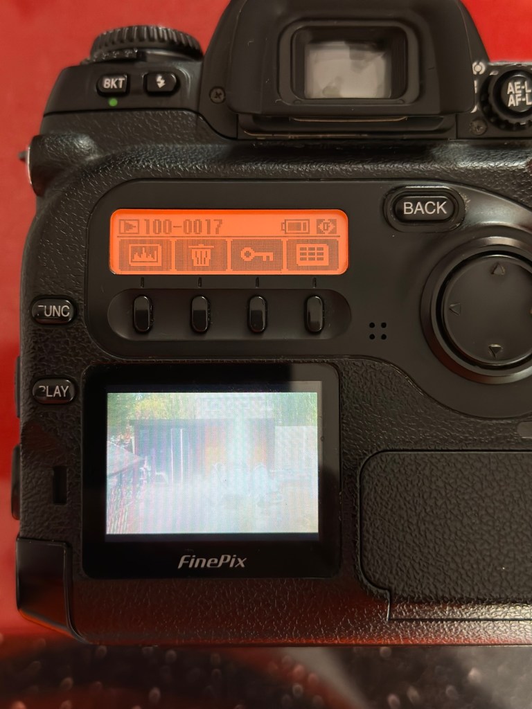
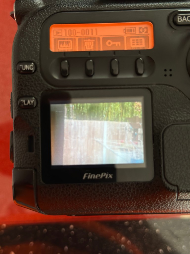
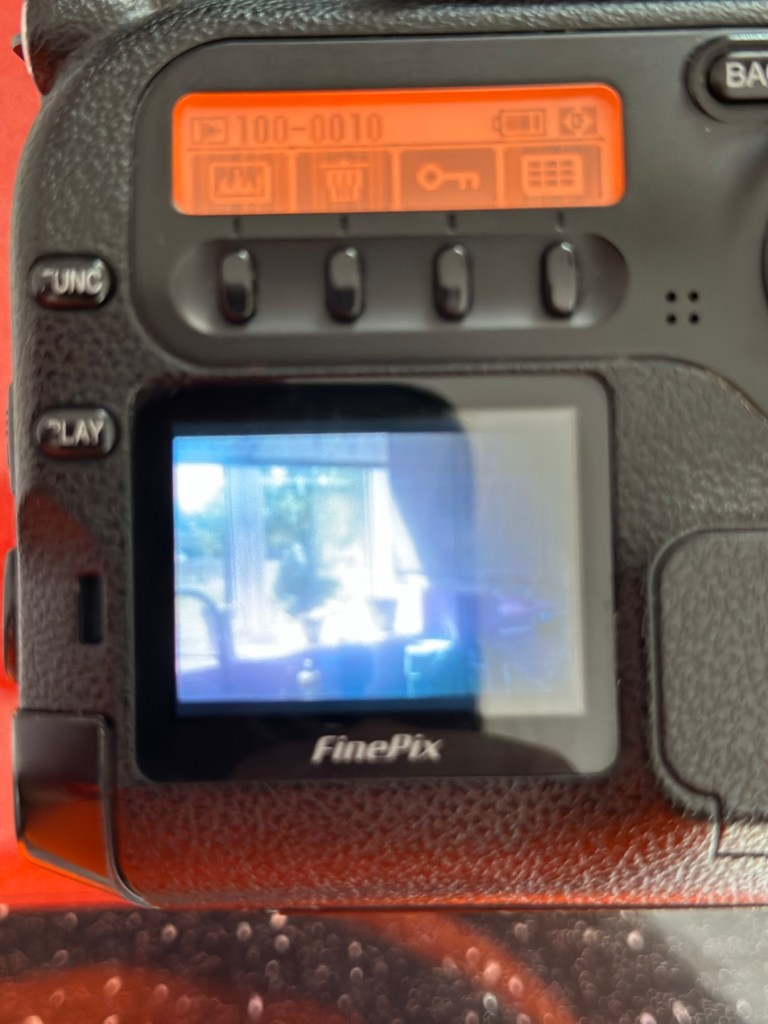
The Finepix S2 Pro
I’ve purchased three cameras as a job lot in an auction. All of them have issues but the issues have not been clarified. This is very much a “Suck it and see” auction where I get what I’m given. I’ve paid £24:22GBP for all three and that includes free postage. I’ve purchased from this seller before who is a bonafide Camera business based in South Wales. He has no time for faulty items though, quick in and out is his way of working, no time to fix stuff. I’ve got three good cameras in this bundle and this works out at just about £8:00GBP per camera. And where can you get cameras like this for those prices nowadays.
I’ve just read a blog where a guy had one of these cameras from new, and in 2002 he had paid £1550.00GBP for this camera. Wow, and here i am 23 years later paying the grand total of £8:00GBP for one. Even if I don’t get it working, I’m happy with that.
Now this particular camera had two issues in its lifetime that caused concern, and one of them meant it was pretty much game over, and that one was the CCD issue that used to plague this range of cameras. Fuji released a whole bunch of these cameras with a faulty CCD that had to be fixed under a recall. They built sufficient replacement CCDs to cover the recall and that was about it. There were no remaining CCDs left and at that point what was left had become as rare as hens teeth. If you suddenly developed that faulty a later date, then tough…you were stuffed.
Serial numbers affecting CCD problems are listed below:
Model Serial Number Range
FinePix S2 Pro 31A127**~31A143**
32A000**~32A039**
33A000**~33A007**
34A000**~34A004**
Fujifilm
The second issue was with a batch of these models that had a “bad” resistor in the power circuit that prevented lock up if there was a power spike, if this failed then the camera just stopped and you were stuck. There was another recall on the second issue but there is probably a lot of cameras out there that again weren’t part of this recall. And I guess owners were pretty fed up of recalls at this point and were off loading their equipment as quick as they could.
The serial numbers regarding the lock up problem are listed below:
Between serial numbers 24L00441 and 24L00680 Between serial numbers 24L01057 and 24L01256 Between serial numbers 24L01553 and 24L01863 Between serial numbers 24L10257 and 24L10608
Fujifilm
My camera serial number
Above you can see the serial number for my camera. Thankfully my number falls outside the range of any of the cameras inflicted with either problem, so it’s fair to say (Fingers crossed 🤞) that I shouldn’t suffer with any of the known issues with this unit. In layman’s terms I think i may well have dodged a bullet here.
I did speak to the seller regarding the fault on this camera and he stated it was just a general error code on the top screen. There is a general error that arises occasionally regarding certain lenses where they have to be locked on their minimum aperture for the camera to work properly, however I’ve not attached a lens yet so this cannot be confirmed.
Here’s some history:
The Fujifilm FinePix S2 Pro is an interchangeable lens digital single-lens reflex camera introduced in January 2002. It is based on a Nikon F80 (N80 in the U.S.) film camera body that was modified by Fujifilm to include its own proprietary image sensor and electronics. Because of the Nikon body, it has a Nikon AF lens mount and so can use most lenses made for Nikon 35 mm cameras. It is autofocusing, with an electronically controlled focal plane shutter with speeds from 30 sec. to 1/4000 sec., built-in exposure metering and pop-up flash. Its ISO film speed equivalents range from 100 – 1600. The S2 Pro also has sound recording capability. The camera is no longer in production, having been superseded by the Fujifilm FinePix S3 Pro in February 2004.
Aside from the Nikon lens mount, the camera’s principal distinction is its 6.17 megapixel photo sensor. Known as the Super CCD, it is unique in having its photodiodes oriented diagonally rather than horizontally and vertically as in all other DSLR cameras. This allows the use of a sophisticated interpolation system that produces an output image equivalent to 12.1 megapixels. The apparent resolution of images in this interpolated mode lies somewhere between 6.17 megapixels and the 12.1 megapixel interpolated output.
A huge number of these cameras were built using a Sony sourced defective CCD that was subject to a recall by Fuji. The recall ended when the stock of these replacement CCD’s was depleted. There is word that no other stockpiles exist of this Super HAD CCD, making these cameras that are found with the purple or black tinted image problems extinct, only usable for parts. The Fuji F700 used a similar defective HAD CCD, but in 3.1/6.2Mp size. That camera has met a similar fate.
Wikipedia
So let’s hope that we can get some pictures out of this unit. We just have to wait and see what arrives.
Assessment:
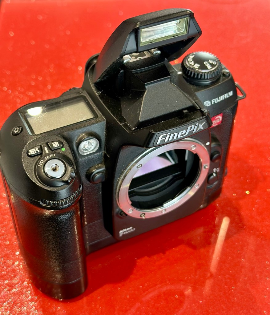
Well the camera has now arrived, and I must say it is in an absolutely beautiful condition. Cosmetically there isn’t a scrape or scratch, all screens are scuff free and it looks as if this unit has been well cared for. It just needs a wipe over to clean. The package is just the camera body with no extras such as a body aperture cover or neck strap, but who’s worried about that, they can be procured at a later date.
Front viewRear viewFlash openNikon type F mount
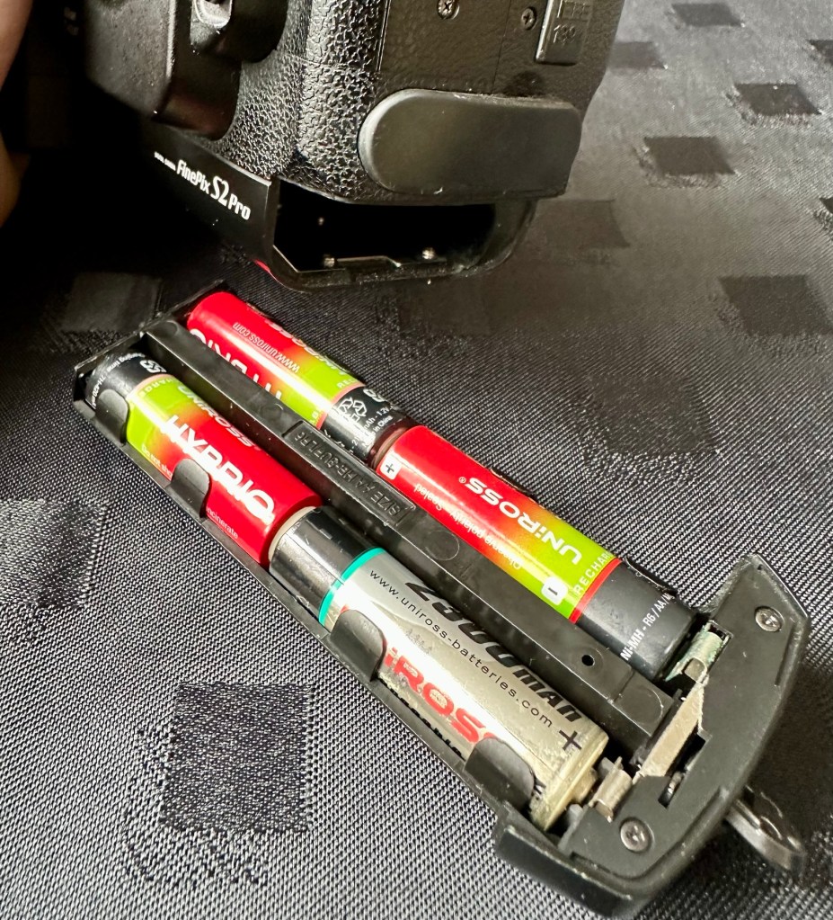
These units are quite power hungry requiring a total of six batteries. 4 AA cells go in the base and two Lithium CR123A batteries go in the grip. These batteries work in unison, one set handling the basic camera functions whilst the other deals with the capture and processing of images. It’s a strange affair, loosely based around the same setup that was originally on their film based camera counterparts.
AA batteries CR123A batteries
I’ve had to order the lithium batteries, however I can still get displays and Information using just the AA batteries in the base, basically it is semi functional in this situation.
The lens mount is a standard Nikon F mount, I’m going to have to search through my equipment to see if I have such a lens, I suspect I don’t, so I may well have to purchase a small lens purely for test purposes. I have some other Nikon repairs in the queue, so a lens to have for test purposes wouldn’t really go amiss.
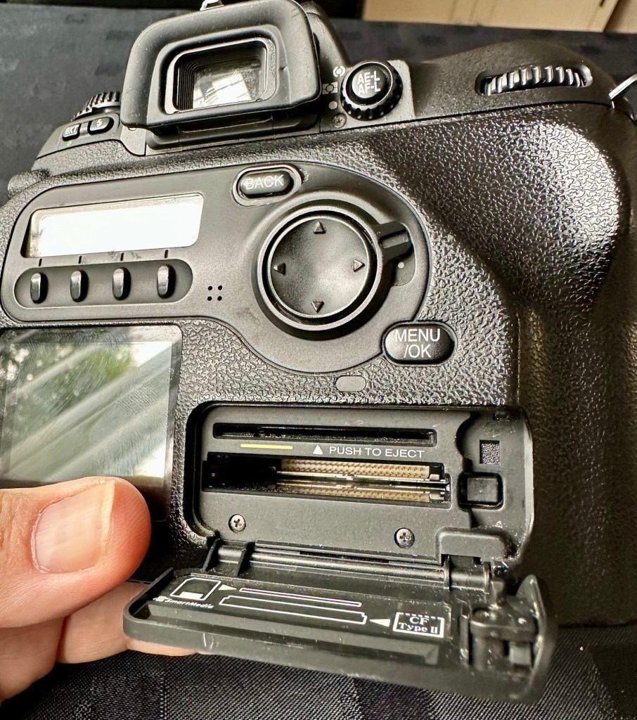
The unit takes either a CF card type II or a Smart-media card (Max size of 2Gb on both) that is located behind a hinged section on the rear of the camera, these work fine and have no bent pins.
Media card ports at the rear
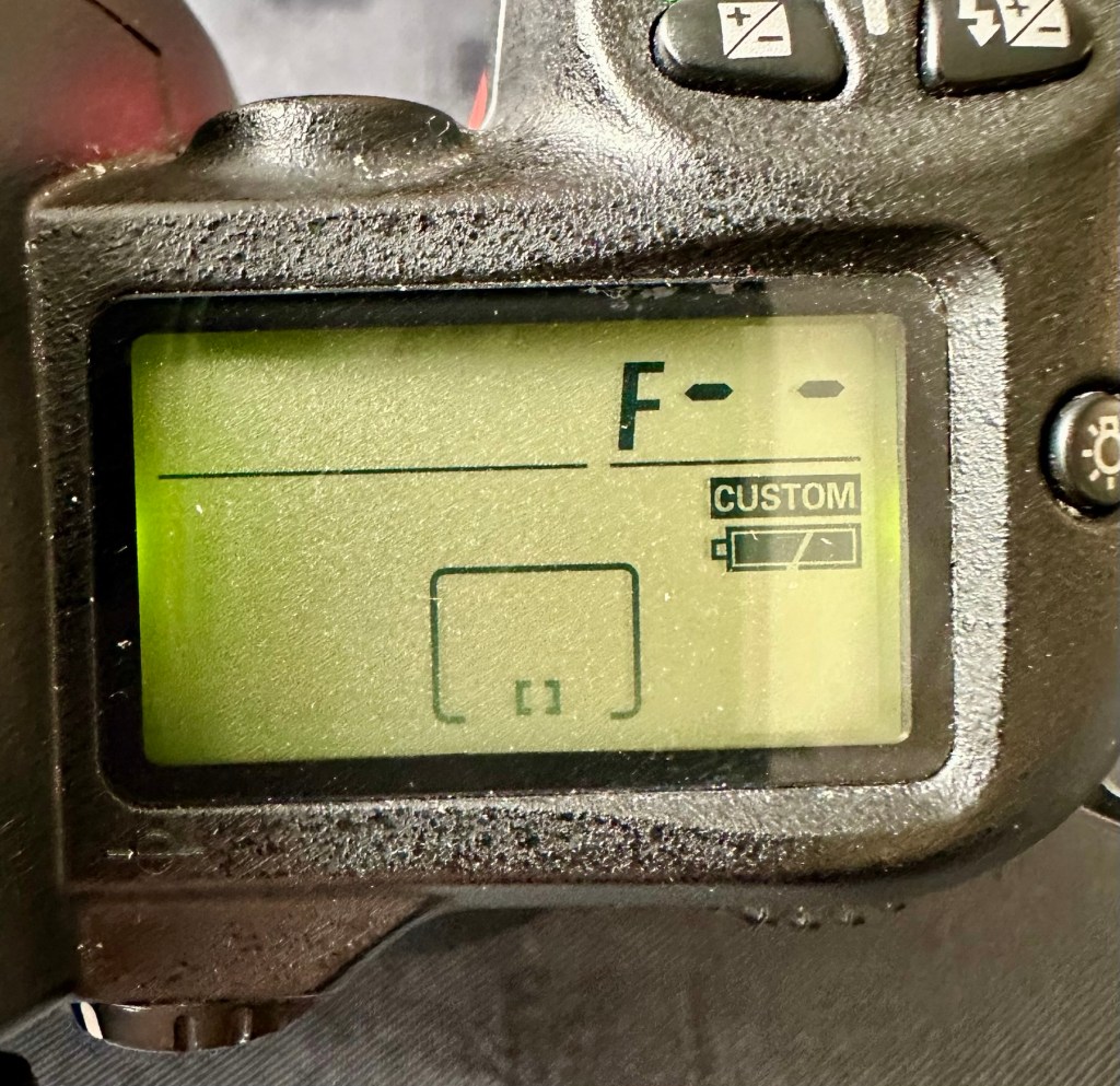
With batteries in place I get the full range of menus, and nothing comes across as suspect at all at this stage in the assessment.
The top menu – no lens attached to test
The top menu by the exposure button is the only “F” indication showing, I have no lens attached so this might be the reasoning for that, but if I do put the menu into manual mode I get the full range of shutter speeds and can even operate the shutter, the shutter seems to be working at all selected speeds with no issues as far as I can see.
Some of the shutter speeds available in manual mode
All other menus are available and I’m even able to format the CF card via the cameras menu. The picture you see on the screen was taken on another camera. It wiped fine so no issues here.
Various menus and the screen after a format was completed through the cameras menu controls
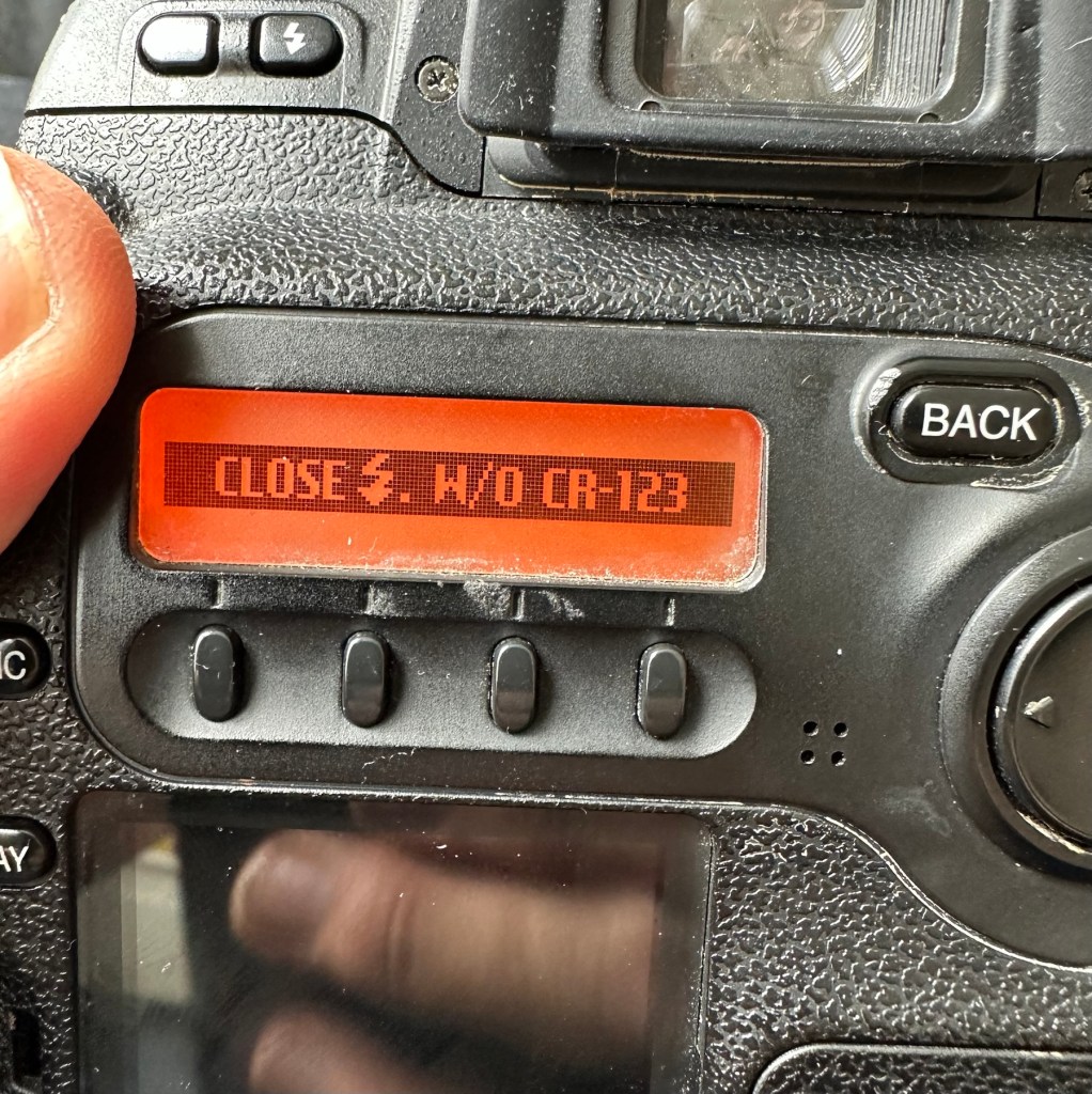
The camera seems to be working with no apparent communication issues as yet. When you try to use the flash it even informs you that you need to insert the correct batteries to test. As I’m awaiting the CR123A batteries I won’t be able to test the flash functionality until they arrive.
No CR123A batteries installed? – You can’t use the flash
As I have stated the testing can only go so far until I have the missing items in my possession, for me that is the two missing batteries and a suitable lens. I’m currently in the process of procuring both. Physically there is nothing wrong with this camera after spending a good couple of hours going over it. I’m quite comfortable with it and believe it could be a lens communication error or just a failure to read the instructions properly by the previous owner. All I need now is that lens. I’ll let you know what occurs in the repair section.
Repair:
To be quite honest it’s not really been a repair, it’s been more of a “pre flight check” to collar a phrase, going through all of the cameras capabilities and ensuring that they are all functioning correctly. As the camera was listed as faulty, and the fault was not identified, I have had to do many hours of testing and Investigation to get to this point.
I’ve done a bit of shopping and managed to buy a nice little lens from the Southern hospice group. Always happy to help a charity and secured this at a good price of £15:50GBP, and that includes the postage, for a Sigma 28-200 f/3.8-5.6 Ø72 Zoom Lens Nikon F Mount. There looks like a bit of fungus on the outermost optic, however I can always clean this if it’s too bad. If not I’ll just leave as is for the moment and keep it vacuum bagged between uses, I can always do a separate post on cleaning up fungus in a lens at a later date. (I have done a basic fungus clean in the past : Canon EF lens 35-80mm)
My new – old test lens
I wasn’t looking at spending too much here, as I only wanted a lens to test a number of Nikon repairs I have upcoming as well as this S2 Pro. This lens will fit that role perfectly, and be added to my collection of other lenses that I have that allows me to test a range of different camera products. I have also purchased an “F” mount body cover for the camera to protect the unit when there isn’t a lens attached to it.
The two CR123A batteries have arrived and have been placed in the handle grip. The warning that was there before the batteries were installed (see picture above) has disappeared and when placed in manual mode the flash fires just perfectly, no issues here.
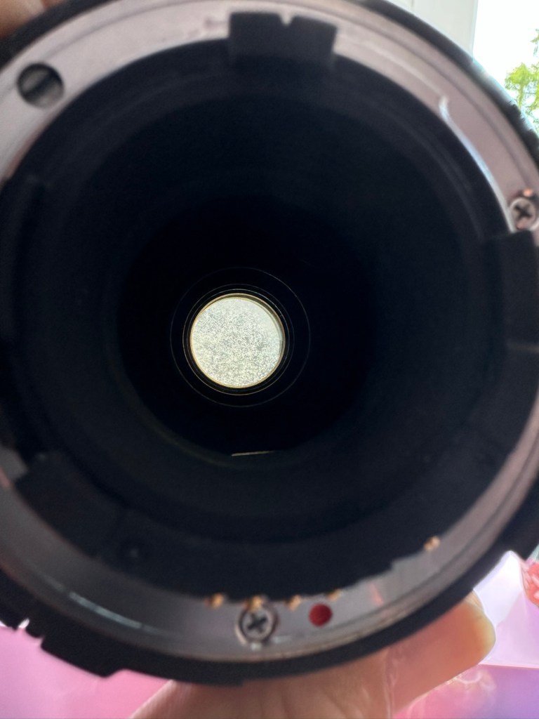
The Lens has arrived. Good point is that it fits fine and looks good, and all electrical contacts are good. Bad point is it has severe fungus throughout, and is just like looking through a fog.
Severe fungus in the lens
I will do a separate post on cleaning this problem up in a later post. However I’m not overly worried at this point, I paid a very low price so it was to be expected, I’m not complaining to the seller who was a Hospice, they need the money and I can fix it so there really is no problem.
That lovely looking lens hides a problem
The excellent news is that the lens does exactly what it should. The camera indications are good, all working exactly as expected . However the pictures via the screen are extremely hazy due to the fungus infection on the lens. There are no black or purple casts on the pictures so I am quite happy that we haven’t inherited the dreaded CCD issue discussed earlier in this post.
Hazy days – Lens fungus
If I use the lens wide open and pop the camera into auto mode I do get an “ERR33” code and that is a communication issue between the lens and the camera. As I have stated earlier in this post, you have to have the lens set at its lowest aperture and locked for the error code to go. Fortunately this lens allows you to lock the aperture and once this is done the camera takes over the exposure when it is working in automatic mode. So as I also stated earlier, it appears the seller was probably not aware of this requirement/issue.
Result:
We have a fantastic working camera, it does all it was produced to do, it has its little quirks and oddities, but being familiar with these cameras and at least having some knowledge and awareness of how they operate is always a wise thing. Read the instructions and don’t just throw them in the drawer until you eventually sell the camera on as a damaged item, when in fact you were just lacking the knowledge on how it operates in the first place. Instruction manuals are good, they serve a purpose. Knowledge is king.
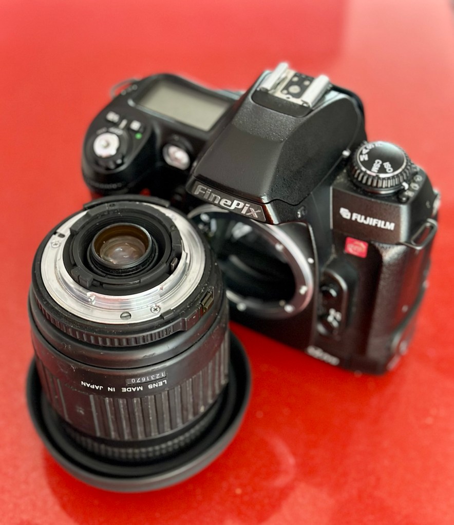
The complete camera with lens
This camera cost me £8:00GBP. That is a superb price for a camera of this quality even though it is now 23 years old. It has a lot of life left in it, and I can’t wait to get it out and give it a real test.
It’s a little beauty – And the lens that needs attention
So in theory I’m confident and happy that this camera is now in a fully operational order, it’s needed a clean, it’s needed a lot of research to find out how it works, and I’ve also downloaded the operating instructions and repair pack should they be required.
It’s taking pictures and storing them. It’s just the lens at the moment isn’t performing at its best due to its fungus on the optics issue. I’m keeping the pictures stored on the card to compare them with the new pictures that will be taken once I have another lens to use.
Once the lens clean up is complete, if I ever get around to it, I will link it through this post.
Edit:
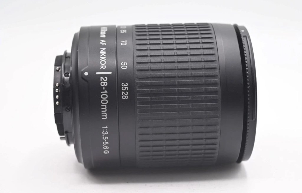
As 12/7/25 I have purchased a newer higher quality lens without any of the above issues to be able to get some instantaneous results, and as I have about seven other Nikon cameras requiring testing, some with sensor issues, it was wise to invest in a better quality lens. I have purchased a Nikon 28-100mm AF Zoom Nikkor Lens G AF-d, in perfect condition and the post regarding it can be found here: Nikon 28-100mm AF Zoom Nikkor Lens G AF-D
A newer – old lens, much superior quality
As previously stated I will add photos in this post once the new lens arrives, to show the difference from the fungus infected lens to a decent lens. The old lens is still a work in progress and I will post about it again as a separate post once the clean up is complete. It will probably be a job completed once the long winter nights are back in situ.
Below are comparison photos between the old lens with fungal issues and this new lens:
It’s just typical for me to manage to make another post from an issue that has arisen from fixing a different item. But isn’t that life? Continuous improvement is a factor we come across on an almost daily basis, and if you deal with old items as much as I do, then there is always something else that needs repairing, something that requires your attention and I just love that. The ability to improve or make something better, gives such a feeling of achievement and accomplishment, and total satisfaction. And that’s why I write this drivel. It’s for me, it’s what this blog was originally set up for. It’s my journal of what I do.
Many thanks for following this post. You know it is always very much appreciated.
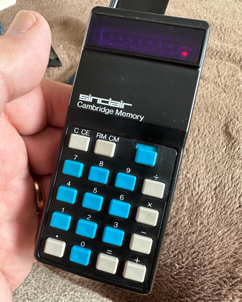
This auction is for a used cased Sinclair Cambridge Memory pocket calculator and original case. The item is in very good cosmetic condition as is the case which still has its instruction sheet. The item is powered with 4 x AAA batteries (not supplied) and does work although 1 of the digits is faulty and does not display (see pictures) plus the number 5 digit is not working. Please refer to the pictures and description provided before bidding.
EBay
It’s faulty…obviously
So it does work, but it doesn’t? This calculator is a model one memory calculator, that dates from around July 1973, ( Actually May 1975 see photos below) and is one of the earliest available mass produced electronic calculators available in the UK at the time. And it was produced in collaboration with a guy called (Sir) Clive Sinclair, who in the following decade would become synonymous with tech development in the UK. It retailed at £29:95GBP, and given the rate of inflation, its cost today in 2025 would be a staggering £463GBP. Wow!
Courtesy of Vintagecalculators.com
I love collecting old calculators, I couldn’t afford one back in the day when they arrived on the scene as I was only a child and probably only on about 20 pence a week pocket money, and savings and investments were not even known to me at this period of my life. The thought of saving that precious 20p a week for the next 150 weeks wouldn’t have even remotely crossed my mind. What no sweeties?
But I can buy them now, so no big issue!
So this one has become available, and I’ve been tracking it for a week or so, there were nine other people watching but I secured it for a total including postage of £14:49GBP, and I’m happy with that, it’s a piece of retro history for a very good price. Even if it remains faulty, or should I say working but not working?
This unit obviously has its problems, the button number 5 doesn’t work and one of the led digits is also not functioning. Hopefully I can get these issues sorted and soon have the calculator back up and working as it should. That would be nice. I’m looking forward to this little project.
Assessment:
It’s arrived and it’s a lot smaller than I anticipated. It has a separate hard protective case, which is a nice touch and a small info sheet on its operation. Cosmetically it’s in a good condition with just minor signs that are age related. There are no gouges or scars so it has been treated well, though it’s not pristine.
Two buttons unresponsive and one LED
Batteries go in ok but, I believe old style AAA batteries were a little wider than those used today and would sit a bit more snuggly in the battery compartment. As you can see there is a little wriggle room here, and springs at both ends need adjusting to help prevent this. I may have to use some spacers so the batteries sit tighter in place.
Gaps between batteries – means movement
The switch is a bit temperamental and can be seen quite plainly from the battery compartment. It looks strangely out of place with no batteries in place.
Switch offSwitch on
It is such a basic design solely relying on tension of a small metal plate to short across the connection points. Should be a simple enough issue to sort.
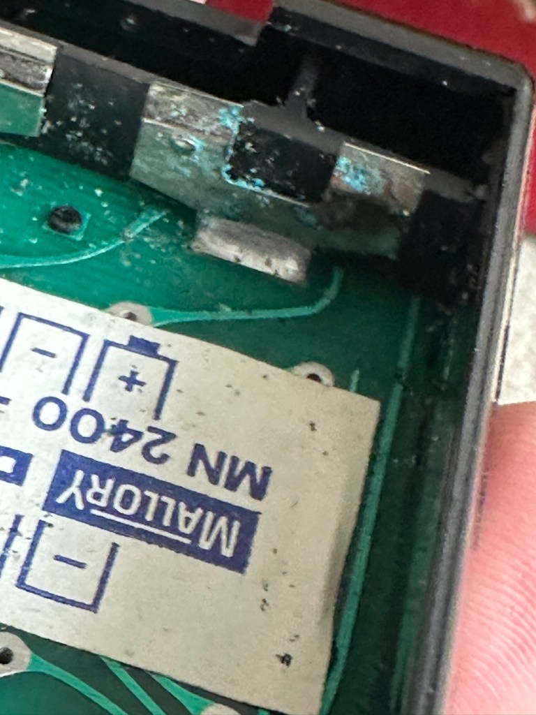
There is a little battery contamination on one of the battery contacts, again this shouldn’t be too much of an issue and should clean up ok with some IPA.
Some battery contamination
It was originally reported that there was one unresponsive button this being the number “5”, there is also another unresponsive button, the multiplication “X” button. There is also one LED indicator, the 4th one in from the left hand side that is not operating. Add to this the issue with the On/Off switch and the contamination, and the original faults reported in the original sales pitch have now doubled. I just wish people would spend more time going over the issues and then give actual accurate feedback as to what the real faults are, it would make for a far more pleasant buying experience. Rant over.
There doesn’t seem to be a single screw holding the body together, I just hope it isn’t all heat welded.
Let’s try to get inside.
Repair:
Well it cracked open quite nicely with no issues with just a plastic flat prise tool. The main board just sat comfortably in the unit, secure, and not a screw in sight. Strange as time moves on some of the games units I come across have best part of fifty of the little blighters to remove before you get anywhere. sometimes the old way is good.
Bare boardOpposite side of boardDate is May 1975
The dismantling of the keyboard is a little complex and you have to take time and make sure you know how it’s going to go back together, it’s just a bit fiddly. The board is quite straightforward and as soon as I see some of the IC’s it dates the unit perfectly. The chips are dated May 1975, and that is about 18 months younger than what I originally thought, it’s quite informative to get inside and learn occasionally and this is just as good as having a birth certificate presented to you. All good stuff.
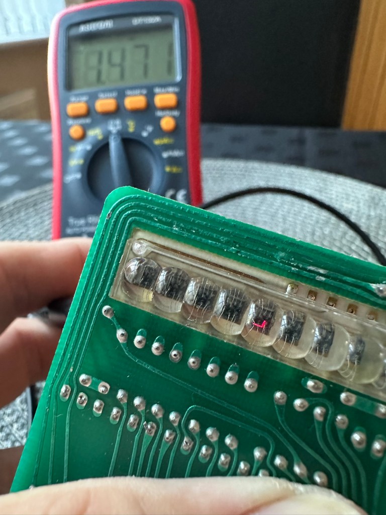
I’ve proved that there isn’t a problem with the missing digit on the display as using my multimeter in diode mode I am able to prove that this LED is working fine.
LED working
The picture shows just one part of the display range on this particular digit, I can assure you all other sections of the display are also working.
Regarding the case with the buttons not working. I have checked this out for continuity and both digits go through the same portion of the main IC and there doesn’t appear to be any broken traces. It’s a strange one but I have also found some really poor solder joints that are either cold joints or just poorly soldered from the start, there are a couple of resistors that need re soldering. It may be nothing at all, but it needs attention, a full reflow wouldn’t go amiss or take too much time.
Faulty resistor joint
I’ve reflowed the entire board due to there being a few cold solder joints.
Full reflow completed
On top of this I have taken off two old capacitors and tested them out of circuit, and both were out of their operable range of +/- 10%. As a result of this I have replaced the offending components with comparable new ones.
Old capacitorsNew capacitors
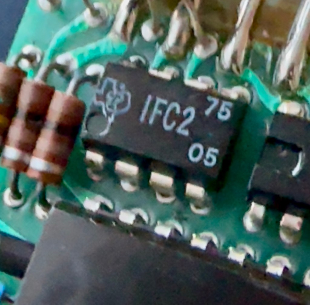
Even with all these extra tasks being undertaken there is absolutely no change in the way it operates. Nothing has gotten worse, the faults that were originally there still remain. I have done some research on line and carried out some further tests and checked expected voltages, most are within range except one that appears to be less than its expected value. After testing everything on this board, every component I can only surmise that one of the three chips has failed, I suspect very much that this, the main chip, a CZL550 integrated circuit. Otherwise known as “Calculator on a chip” is the one that is at fault.
A CZL550 chip
To be quite honest these chips are fairly rare and command a price far in excess of what I paid for the original unit, and I don’t really want to do that. I think I’ll wait around to see if I can secure another faulty unit to complete this repair, so in the meantime, and until I can secure such a unit I will put this repair on hold.
Result:
Well, it’s not what I wanted but sometimes you just can’t win with some of these old projects. In no way am I walking away from it, it’s just that the parts are so difficult to get hold of that you really do have to just wait until a sufficiently faulty one comes up for sale. And that could be days, it could be weeks or months. So for now i admit defeat, but it will not be going to trash. It will remain in my ever expanding “To do” box, for me to pick up on at a later date. And when I am in a position to move this project on, I’ll pick it up in a continuation of this post.
Many thanks for passing by. It’s always appreciated.
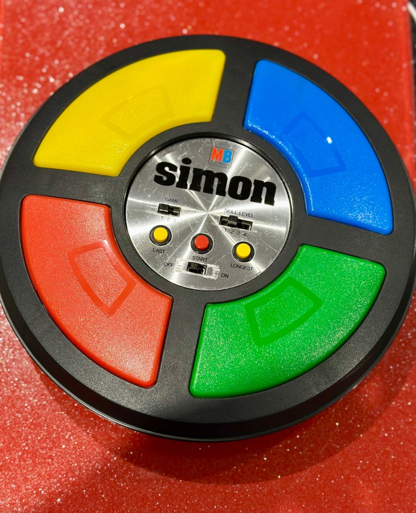
Remember this? Everyone had one around 1978 apart from me that is. Well, now I’ve got one, only 47 yrs late and it doesn’t work. But hey that’s what this site is all about, and that’s how I roll. Always late to the party, and even then you’ll probably find me in the kitchen 🥳
What the listing said:
Cosmetically in very good condition but does not work. Please see attached pictures to judge condition for yourself.
EBay
Another one with all battery covers! I’m shocked. And what’s that screwdriver there for?
The guy was after £17:00GBP and that included postage, but I put in a cheeky bid and managed to get it with postage for £9:80GBP. Anything under a tenner is good in my eyes.
Here’s some history:
Simon is an electronic game of short-term memory skill invented by Ralph H. Baer and Howard J. Morrison, working for toy design firm Marvin Glass and Associates, with software programming by Lenny Cope. The device creates a series of tones and lights and requires a user to repeat the sequence. If the user succeeds, the series becomes progressively longer and more complex. Once the user fails or the time limit runs out, the game is over. The original version was manufactured and distributed by Milton Bradley and later by Hasbro after it took over Milton Bradley. Much of the assembly language code was written by Charles Kapps, who taught computer science at Temple University and also wrote one of the first books on the theory of computer programming. Simon was launched in 1978 at Studio 54 in New York City and was an immediate success, becoming a pop culture symbol of the 1970s and 1980s.
Wikipedia
From what i can see in the pictures the item seems good, cosmetically. I may be able to see just a little contamination around the battery contacts but I can’t be sure. It worries me when i see a picture that shows a screwdriver alongside the item you are buying, it just screams at me that the seller has been in side and is not being truly honest about its issues. Let’s just wait until it arrives to do a full assessment. I’m genuinely excited about getting this working, as my age veers ever closer to the higher numbers. I need something to stimulate my mind, what’s left of it. 😂
Assessment:
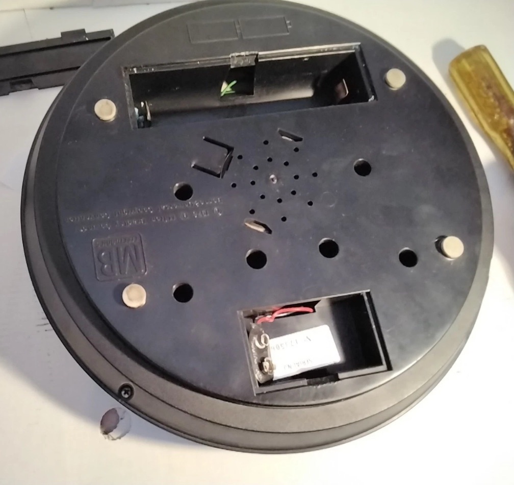
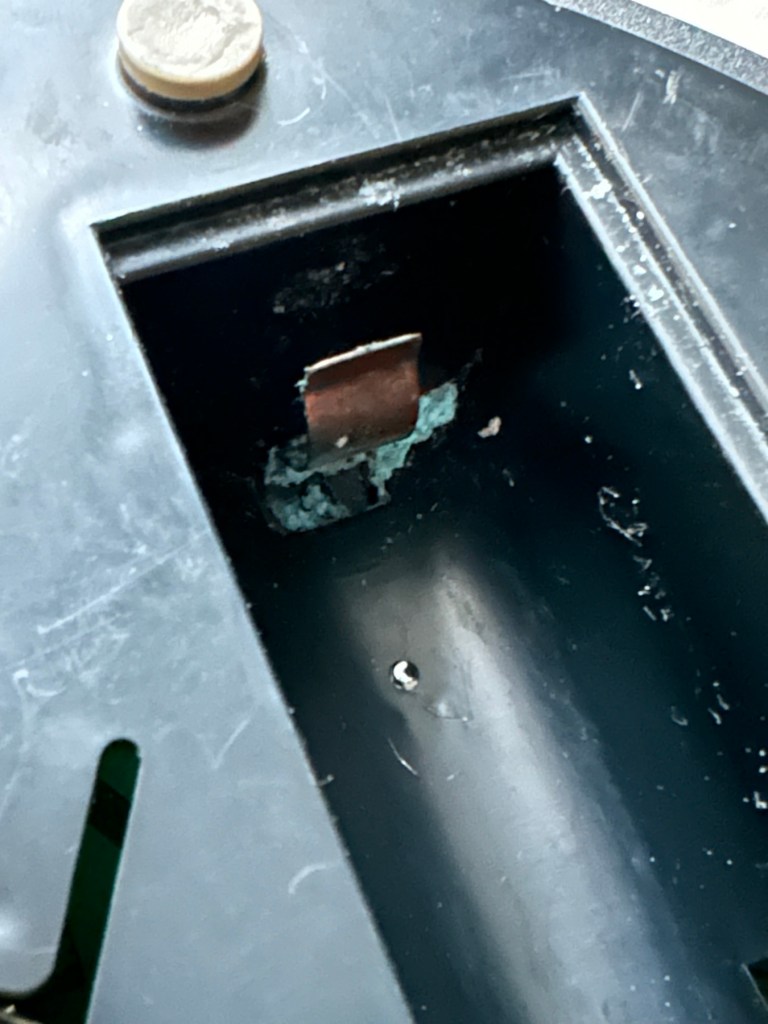
The unit has arrived and on first impressions looks clean and tidy cosmetically. The pads are not very responsive and the battery contacts are seriously corroded. The unit is a power hungry beast, taking two ”D” cell 1.5v batteries and one PP9 9v battery. The unit does not work with its batteries in place, and i’m not surprised really, and to round it all off two screws are missing from the case, and one screw mount is broken. All four plastic springs that sit under the coloured pads are broken, and just to clarify someone has already been in here and it doesn’t bode well. My previous concerns of a screwdriver being in the original photos have been confirmed. It’s been tampered with.
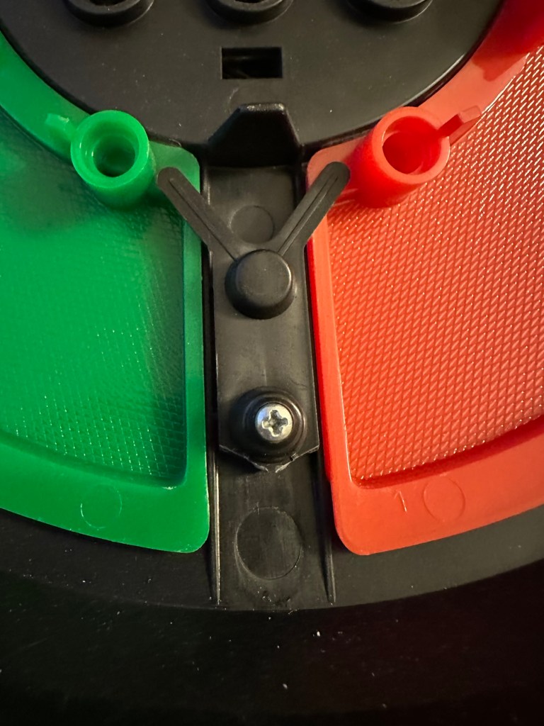
Broken screw mounts and contamination Bad contacts – contaminated Pads unresponsive due to broken plastic spring mounts
The board is a typical of many circuit boards from this era that were produced for MB. I had a similar circuit board on this item here: MB – Computer Battleship
Top of boardUnderneath the boardYou can see the board structure that is typical for this era. The contact points are indicated by the red arrow marks.
In the picture above you will see two arrowed points. These points are the power contacts that make contact with the two seriously corroded battery contacts you can also see above. No wonder there is no power getting to the board. I suspect this might be the cause of our electrical problem.
Repair:
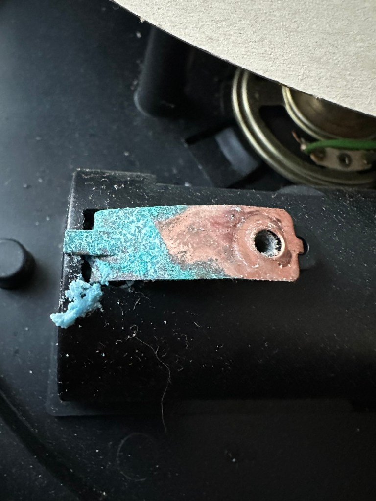
First thing to do is to get those battery contacts cleaned, as well as having a good clean of the main board. This has now been done. I’ve repaired the broken screw post by simply using a rubber washer that has been sufficient for this repair.
Contacts before and after
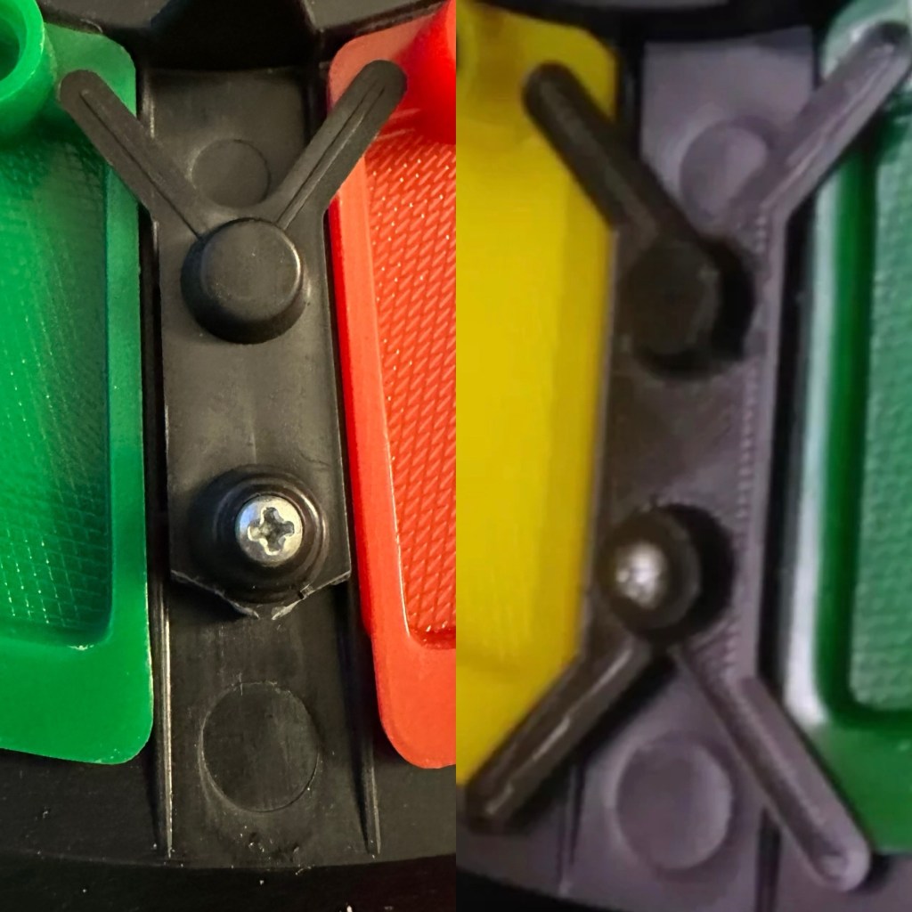
A friend of mine has kindly offered to print me off four of the “Double Y” springs to replace the ones that are already in place and broken. He owes me a favour or three and needs some subject matter to run through his new 3D printer so I’m very pleased to help him, as pending the outcome I may well buy one myself, as I have been threatening to do so for a while now. This should sort out the issue of the unresponsive pads, first found in the assessment of the item. He’s panicking that they might not be smooth and beautiful, I’ve told him not to worry as they are hidden inside anyway.
What I currently have on the left, what I’m expecting on the right
He’s just supplied me with five double “Y” pieces just in case one is damaged in some way. Let’s get these put in place to see the difference these make.
Out with the oldIn with the new
With the new springs in place the pads are working as they were originally designed to, now with some springiness in their operation. The battery contacts have now also been put back in place.
Cleaned contacts back in place
When assembled, the buttons are a little erratic and not always responsive so I decide to look into this further. A quick Look at the board shows that the solder contacts on the board for all of the button connections are worn, the solder has failed so I decide to reflow all these solder joints to improve the contacts. This appears to have worked as the unit when reassembled, now has uninterrupted operation. This is an age related issue. A simple fix.
Old solder joints that have failed and needed re-flowing
Result:
Another 47 year old saved from the scrap heap, it’s been an interesting and sometimes confusing repair and I thank my friend who stepped in to save the day by utilising his 3D printer to make some parts. Without his assistance this repair would not have been achievable.
Looking smart after a quick clean
It’s just another old piece of retro history to add to my ever growing collection and much to my wife’s dismay. Bless her.
Now working
Thanks for passing by, as always it’s very much appreciated.
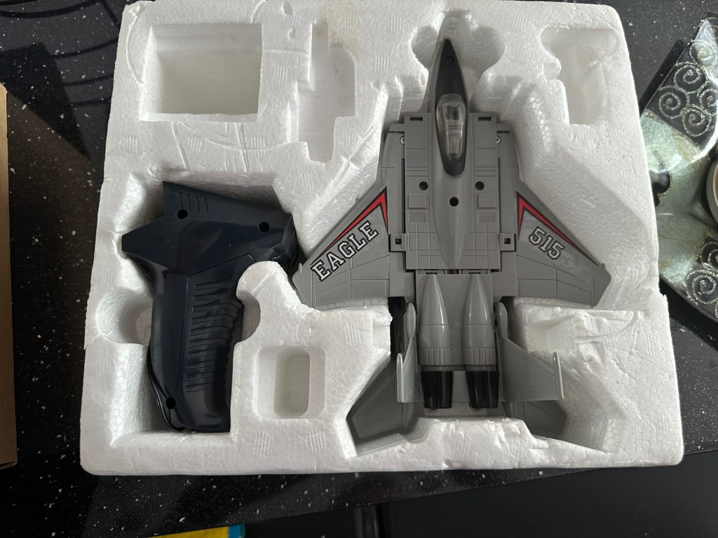
I arrived home from work last evening to find my nephew at home. He’d been looking around his mum and dad’s attic to find his old star wars toy collection he had from the 80s-90s. Whilst in the loft he found this old toy from 1985 by a company called Yonezawa being sold under the Grandstand branding, and it isn’t working. Here is where it passes over to uncle Dave.
Uncle Dave, it’s not working
There’s no real value to these toys as they were produced in massive quantities off the back of all the transformer type toys that were available at the time. There are some accessories missing from this one that are obtainable via the auction sites, he may well ask me to source these, but at the moment he just wants me to get it working to pass onto his boys. The video below shows just what it does….and that’s not a lot. But the one I have here is totally dead and needs reviving just like Frankenstein.
Deltatron what it should do
So here we go…
Assessment:
My overriding surprise is that this has been in a loft space for close to 30 yrs and does not have that expected damp mustiness that usually comes with such an item. I must say, my brother in laws loft space is an exception, it’s obviously free from excessive moisture, mind you it’s only about 40 yrs old so building standards had probably advanced somewhat from when ours was built about 90 yrs ago.
It’s in a good condition and all its parts are there minus a few little additions that originally came with the toy. But as I have stated earlier these parts can be obtained on line if required.
Right, let’s have a look at what is or isn’t happening here…
Repair:
When batteries are installed and the remote control is operated, all that happens is that a light comes on in the toy. The motion that is required is non existent.
The motor unitMotor removed, there is a cog mechanism to move the unitThe motor unit removed
When examined closer you can see there is a lot of surface rust on the side of the motor where the contacts go into the unit.
Really rustyQuick clean later
The contacts were so rusty inside the motor unit that you’d get an intermittent running of the motor if you moved them. I’ve checked continuity and solder joints and they were fine. I’ve injected some contact cleaning spray into the motor and sat there manipulating the motor in both directions for about 5 minutes, this was sufficient to get the motor running freely once power was reapplied. The contacts were dirty and restricting the flow of power to the motor. I decided to use some IPA around the area to give it all a good clean and once again sprayed more contact cleaner through the motor.
Contact cleaner and silicone grease
Once I’d run the motor for a few minutes in both directions I then applied some silicone grease to the cogs and moving parts to allow a smoother operation. It’s worked. A nice simple fix.
Result:
It’s working and here’s a small video to prove it.
It’s now working
I’ve already handed it back and it’s a joy to see the smiles on my nephew and his dad’s face when they watched it working. Such a simple thing, bringing back treasured memories and laughs. Another old toy saved for another generation and best of all another item not going to a landfill.
Thanks for passing by, as always it is very much appreciated.
I’ve had this camera sitting around since March 2023, when I first wrote about its purchase along with a couple of other cameras here: New old stock 📸
Barnet Ensign Ful-Vue II
I’m not sure what I paid for these cameras but it wouldn’t have been a great deal. I love the Ful-Vue due to its looks and the kind of Art Nouveau feel it has about it. It’s a very basic mass produced camera of its time and It is an old 120 film camera, and the bonus is that this film type is still readily available, in fact I still have a few rolls in my fridge at home today.
The shutter is an all mechanical, spring loaded system which swings a piece of metal over a hole to create the exposure. The approximate timing is 1/30th of a second and that’s slow. It is understandable when taking in to account that ISO 400 wasn’t that common in the 50s and would have produced very noisy results. It was far more common to use ISO 50-100 film and that would’ve required a slower shutter speed at the approximate f11 of the lens of this unit.
I obviously want to get it back into full working order. And want to do as sympathetic a restoration as possible. It’s a 120 roll film camera with a 6cm x 6cm frame inside, it was a cheap and cheerful camera of its day, sold as, “Easy, even for a child to use.”
In the meantime, here’s some history about this little camera:
Barnet Ensign Ross Ful-Vue II
Originally released in its initial form in 1939, this version was introduced in 1950 after further improvements were made. The new flash synchronised shutter, the turn-able lens barrel allowing three different distance settings instead of two, an all-plastic front panel, and an optional flashgun. The improved version was called Ful-Vue II. Pictures were 6×6cm on 120 film. It has been stated that colored models (red, white and blue) were sold in 1952-3, to celebrate the coronation of Queen Elizabeth II; However, no other evidence for these cameras has been seen: in particular, the Ful-Vue is not mentioned in a coronation advertising supplement to the BJP Almanac of 1953. Colored Ful-Vues were advertised as ‘Ful-Vue à la Mode’ in late 1952. Examples of the regular Ful-Vue II, repainted and presented as the colored model, have been seen in online auctions.
Camera wiki.org
So I estimate this camera to have been produced sometime between 1950-54 when this particular model had its production run, just prior to yet another version becoming available. Making this particular camera approx 70+ years old. Let’s have a look at the unit that I am now in possession of.
Assessment:
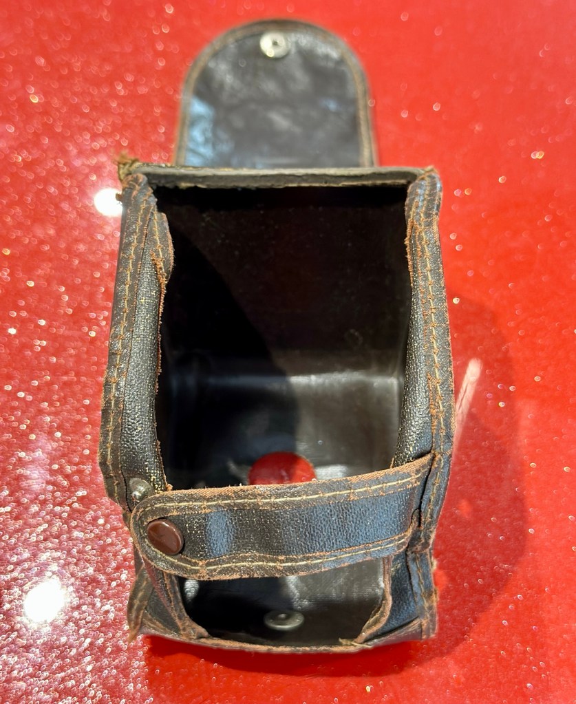
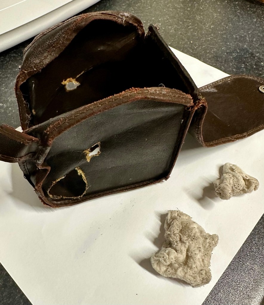
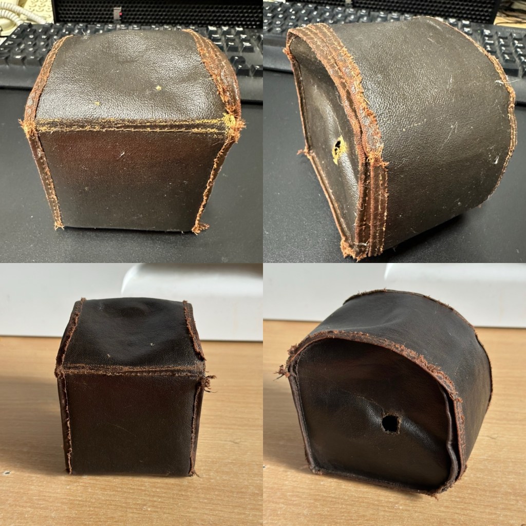
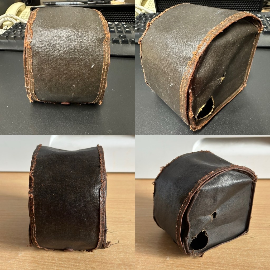
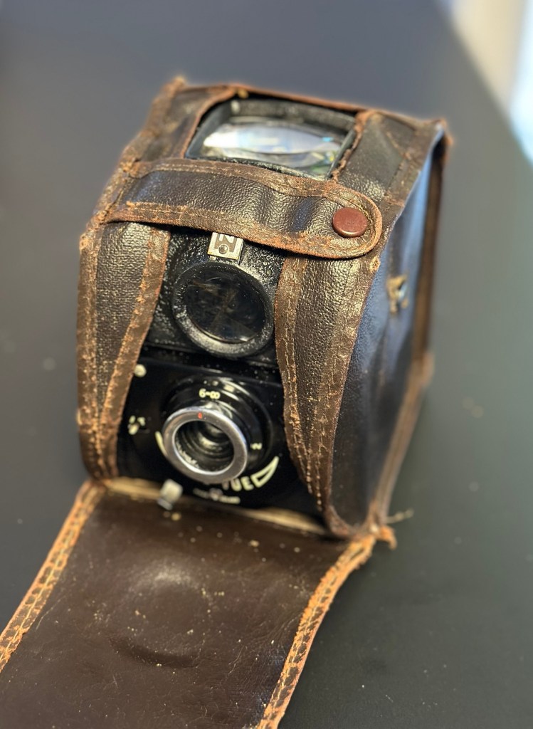
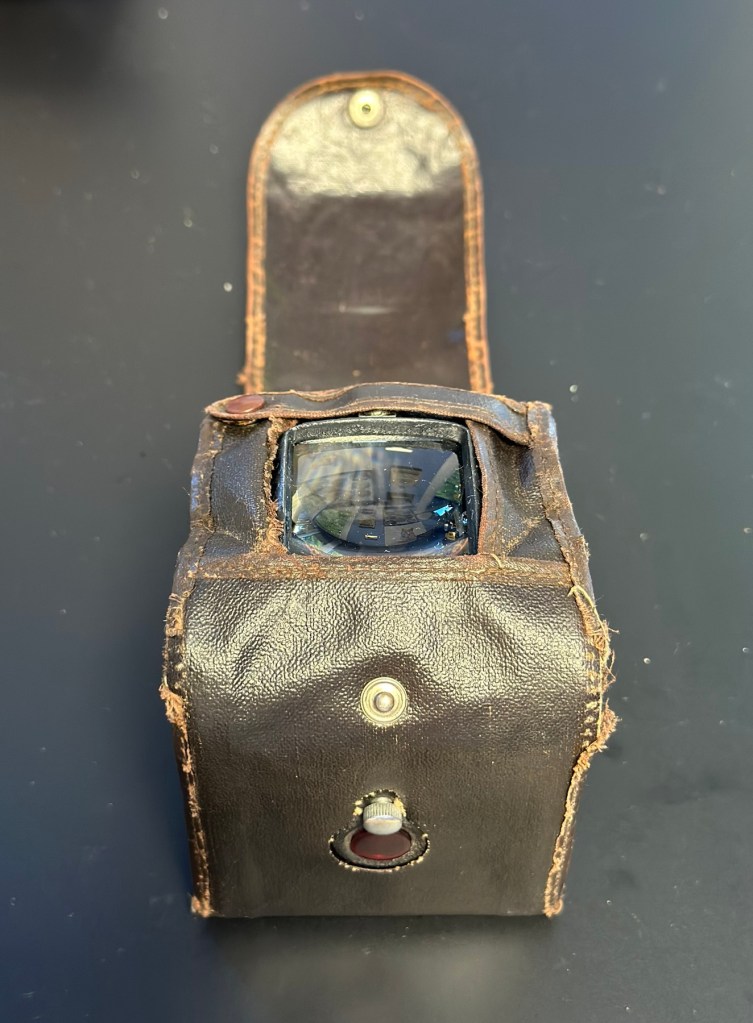
The case is leather and is very dry and brittle, it’s complete, so I may well look at revitalising this one just as I did to an old Kodak camera in this old post: Kodak Brownie reflex. If I do, I will cover its repair in the following section.
The old leather case, very dry and brittle
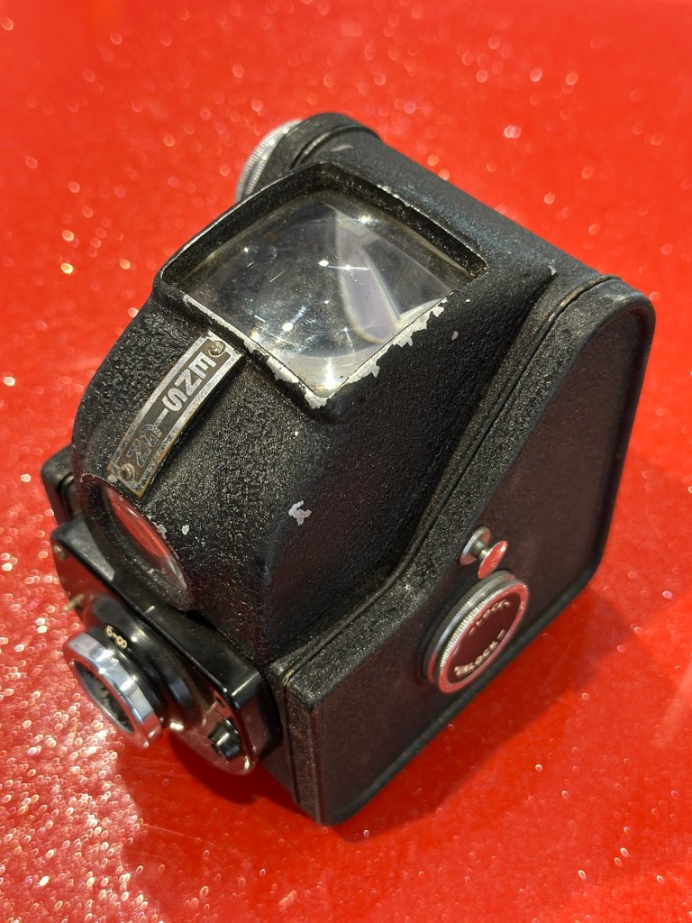
The camera itself is in quite a good condition cosmetically, it has chips off the paint and a little wear and tear that will require some attention. There appears to be a screw missing on the front plate, this will be replaced.
A little wear and tear, nothing too worrying
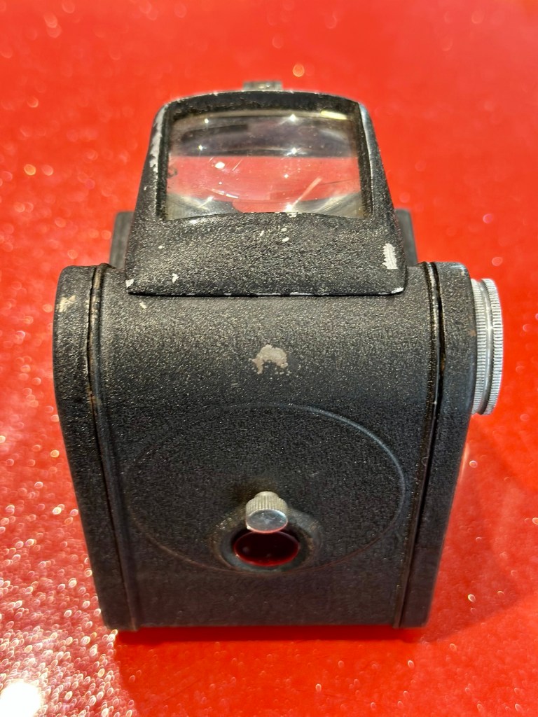
The mirror inside the viewfinder seems to have moved and will need reseating, all glass and mirrors appear quite foggy and need a good clean, all workings within the camera inside appear ok. Light seals appear ok but may well need replacing purely due to their age.
Glass dirty and mirror has movedInternals all okNo issues on the winding mechanism
The lens barrel and shutter mechanism will be checked over to check correct operation, however at first glance, all seems to be ok. There is a little red window on the rear panel where you can see the film exposure numbers. A little thumbscrew can be turned to blacken this window out, this will be very handy for when we try to install a colour film to prevent any fogging issues.
Repair:
I want this to be a sympathetic restoration, so I will endeavour to keep the look and feel of the unit as original as possible.
The case:
I’m starting with the case as this is probably going to be the most time consuming and will require numerous periods of drying and moisturising, it’s probably about 70 years old now and to be honest has probably had no care taken of it during that time.
Mild soap sud wash to clean and introduce some moisture – see the dirt on the used cotton pads
Using some mild detergent, but just the soap suds on a cotton pad I have gently wiped all over the case, paying special attention to any old folds in the material. This has had a dual purpose of removing ing a lot of age related dirt (As you can see in the photos above, that show the dirty cotton pads) as well as adding a little bit of moisture but not too much. I want to do this in stages to minimise any more damage. I will now let this dry for 24 hrs and I will then do the same again.
24hrs later I have cleaned the case again, in exactly the same manner. let’s leave it another 24hrs and then apply a little polish to give it back some colour and a little bit more moisture. I’m keeping it as low cost as I can, no doubt a brown shoe polish will suffice for the result I’m looking for.
I’ve treated the leather and polished it twice using a black shoe polish. The third coat I have given is a tan regimental high gloss polish. I’m leaving this for a few hours and then I will buff the case up. I’m not repairing stitching or holes as I want it to retain age and it’s old look. I just want the leather to look healthier, last a while longer and to get some moisture back into what was a very brittle leather case.
Before and after treatment
I have today buffed the case up after all the treatments of the last couple of days. The case feels lovely and soft and much more pliable than when I first started on it. I’m now going to bring this part of the repair to an end as that’s as far as I wish to take it at this time. I want it to still carry its signs of age. Without further a do, let’s move on to the camera.
The camera:
I have decided to totally dismantle the camera and work on it bit by bit. In this case there is not a great deal to dismantle.
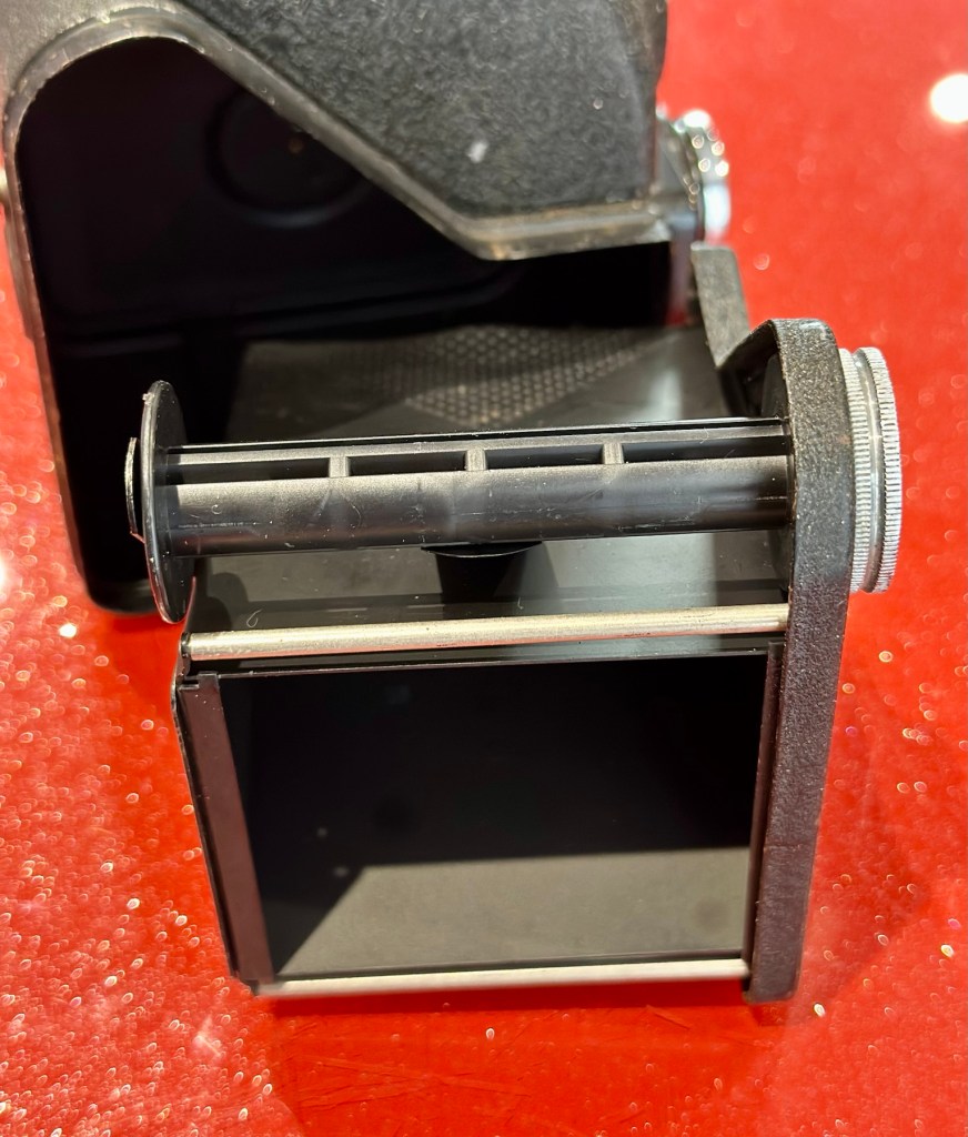
Unclip this spring inside the body Off pops the entire mirror and optics headLoosen the spring to release both optics
Firstly I release a retaining clip inside of the main body and this releases the “Viewing head” on top of the camera. This part of the camera contains the mirror that has become detached, and two glass optics that complete the viewer section of the camera. There is a single spring structure that holds both pieces of glass in place, release this and they just fall out. Easy.
All the glass and mirror removed Rear of the mirror, caked in muckRear of mirror has cleaned up nicely
I’ve started by placing the three optical items above in a mild warm detergent soak. I will leave these there for about an hour, in hope that a soak will help in cleaning that muck off the back of the mirror. The two other optics are in great condition and I’m sure the soak and then a final rinse will be all that they require. This treatment worked just fine, and now onto the next part.
Next I’ve removed the shutter mechanism from the camera body.
Front viewRear viewTaken apart The camera has a beautifully simple mechanism that is a work of art to look at
Here is a very small video showing the simplicity of this shutter mechanism
A The mechanism is beautifully simple and is such a lovely piece of work to look at. To think im probably the first person to look in here in the last 70 years is special. All I’m going to do here is very carefully get rid of as much old ingrained dirt as possible and very gently clean the shutter leaf. I will use a minuscule amount of clock oil on the mechanism only, I will use some fine graphite dust on the actual leaf part of the shutter.
Gently does it, in minute quantities
The lens and mechanism have been cleaned now and reassembled, all tested, and working as expected.
The body work is fine apart from some small chips and paint flakiness. I’m going to retouch these missing areas with some enamel paint and a bit of thickener to enable me to obtain the stipple effect of the original paint job. Then I will finish with a nice black polish.
Touching up missing paintwork, mechanism now attached to body
Let’s now get the mirror back in place and the head back on the camera unit.
Mirror and optics all in place
And that’s it. Apart from a little polish we are now done here
Before and after
Result:
I’ve put quite a bit of work into this little camera. Some people will ask why bother as it was only a cheap mass produced camera? Well, I like it, it’s a lovely little camera and it deserves to be displayed. Now, as it’s also working it’s a big bonus. It gives me something to do, and it’s how I relax, as I’ve been shoulders deep in DIY at home recently and doing my shifts at work, so this is a welcome distraction for me.
All done, just needs a polish once the paint is dryIn its 70 year old leather jacket – nice
So that’s another one saved from scrap. This camera will now go into storage where I will vacuum pack it with some silica packets to prevent it from getting damp. I’m surprised just how good this camera “smells” considering its age, there is no mustiness at all compared to some cameras I get from this era.
Many thanks for popping by, you know it is always very much appreciated.
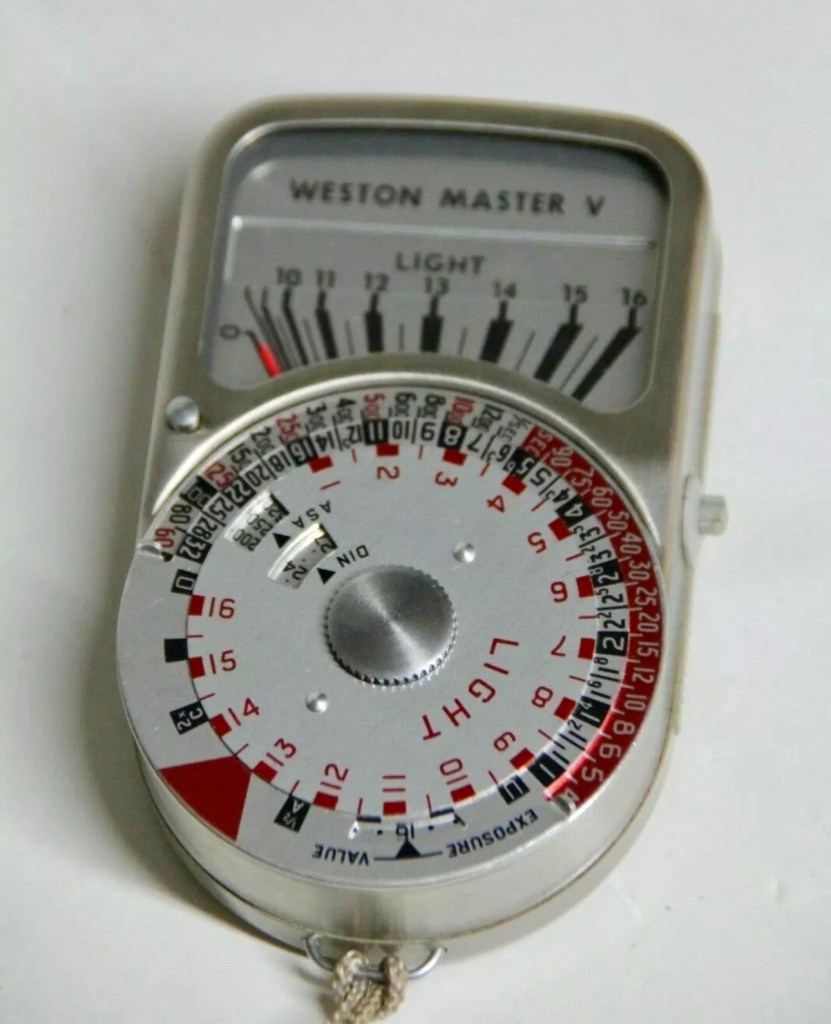
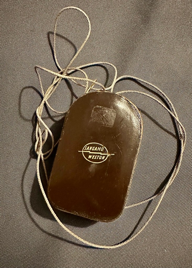
Sangamo Weston Master V Exposure Light Meter includes Invercone & Cases The exposure meter is not working The invercone will also fit the Weston IV
EBay
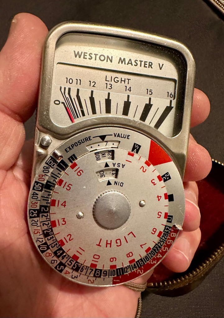
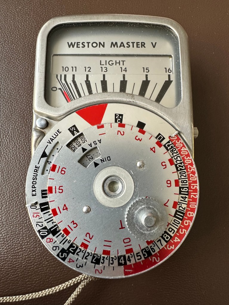
Weston V light meter and Invercone
I have brought a little item from my past history here, going way back to the days when you had to work out the light levels in photography for yourself. The exact date of this unit is unknown, however it was manufactured between 1963 and 1972. That’s two years prior to my birth and up to the age of when i was 7 years old. And I was using them when I went into photographic work approximately ten years later. These units were made to last and did their job well, hence their longevity. I’ve paid the total cost of £8:40GBP and that includes postage. I’m surprised to be honest as not only is it the light meter, but also an Invercone (I’ll explain later) and two cases. An absolute bargain in my eyes as the Invercone itself, in a case can sell for more than I’ve paid for the entire package today. Oh, and it doesn’t work and to be totally honest I don’t think I will be able to get it working ever again, as the suspected component fault is one of those little things that are only dealt with by specialist craftsmen. Add to that the problem of locating a replacement piece, as they are nigh on impossible to obtain, or in layman’s terms, as rare as hens teeth.
But I have read about people reviving these parts and I’m going to give that a try. If I’m unsuccessful it will be a nice piece to get mounted into one of those box frames as a historic photographic memento.
What is this part you’re referring to?
A light meters main purpose is to react to available light and direct the photographer toward making a decision regarding the settings for his camera. Things like ASA, shutter speed and f stop settings.
Therefore it needs something to sense the light. It’s not a solar panel, these were not invented back then, but it was a similar system and it was called a selenium light sensitive cell. When exposed to light, the cell generates a small electric current that deflects the needle of an ammeter coil within a strong magnetic field. The whole system is basically a Selenium cell, a resistor and the ammeter coil. The lightmeter is entirely dependent on the light sensitivity of the selenium cell for accuracy. Over many years the selenium cell ages and degrades to the point that it just stops working. It dies. Its main cause for demise is usually moisture getting into the workings and causing degradation at the contact points on the Selenium cell.
There are a number of posts/sites I have visited that claim you can revitalise these items, however I am sceptical at this. There seems to be only one person in the uk that seems to totally replace these items and that is a guy called Ian Partridge, who I believe charges around £90GBP for a repair and his site can be found Here. A fully working serviced unit can sell for up to £189:00GBP.
I’m not doing that. No way. I’m going to see if I can even get it slightly working, I’m never going to use it seriously again but I’d at least like to see the needle moving without causing any damage to its original design.
Is that the only potential issue?
No of course not. There is one other potential reason why it is not working and that is related to the ammeter coil, the axis on which the needle moves, sometimes it can become stuck, if this is the issue then happy days, the fix would be a lot easier. However this is me, and things are never that easy for me 😂
There is also a fine tuning screw on the rear that someone may have been a little bit too enthusiastic with, in the past.
And of course. The pointer lock on the side of the unit could have been simply left on. Now wouldn’t that be nice and easy?
So what’s this Invercone thing you’re going on about at the beginning?
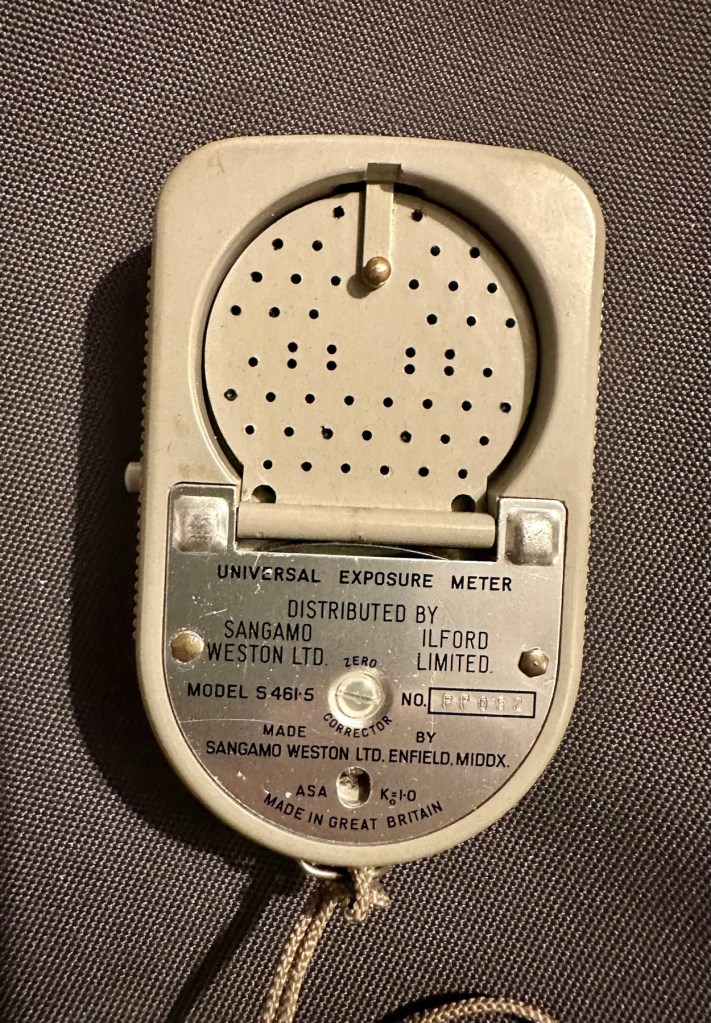
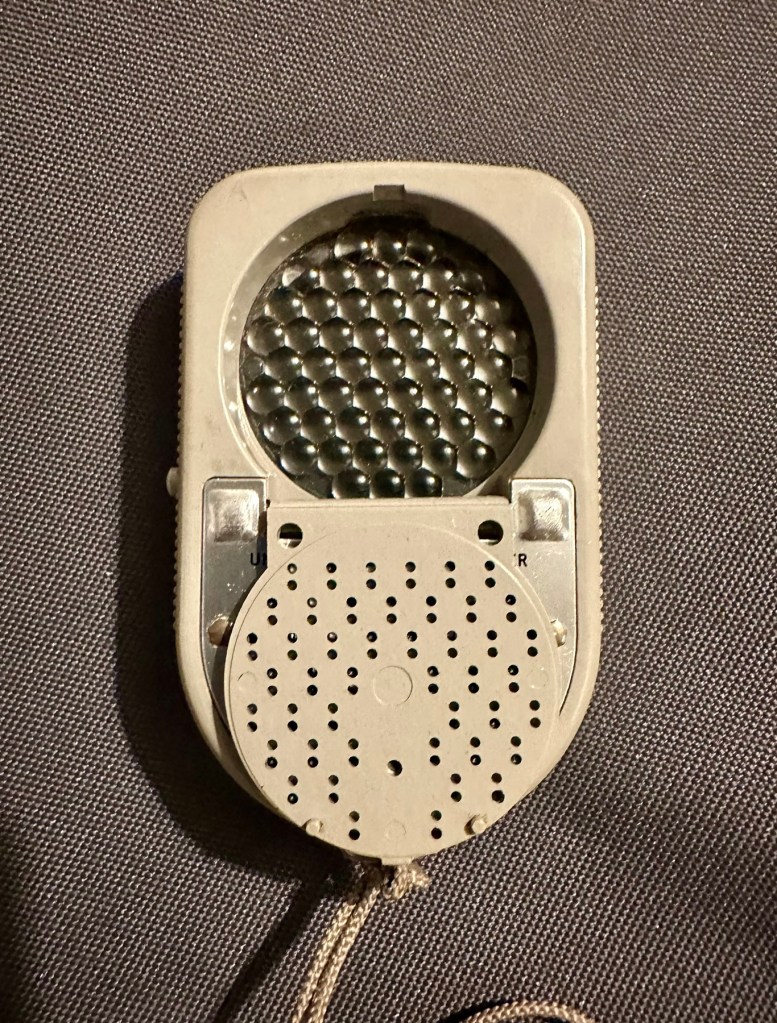
It’s that weird shaped piece of plastic with a bit of metal on it, in the pictures above.. it assists greatly in incidental lighting conditions where there is a back lit scenario.
The inverted cone shape is designed so that as the meter is angled to the light source, the readings remain accurate which they would not do if it were a dome. And because backlight effects the exposure, a small part of the invercone sticks-out beyond the top of the meter case to pick any such light up.
Sangamo Weston was a company that made light meters, among much other electrical equipment. It is particularly known for the Weston Master series of selenium meters.
The Weston Master V was produced in the UK from 1963 to 1972. It was Model S461 in the UK and Model 748 in the US
Weston was founded by chemist Edward Weston—no relation to the famous photographer—who held many patents for electrical inventions, from permanent magnets through cellulose manufacturing, dynamos, arc and filament lights and the magnetic-drag speedometer to electrical measurement instruments (and even US 895218 – a fruit box!). Weston’s son, Edward Faraday Weston, applied for a U.S. patent on the first Weston exposure meter, granted as No.2016469 in October 1935. This was a cylindrical case with an electrical meter at one end, and an iris at the other; an adjustable scale around the meter opened and closed the iris, and showed the exposure.
Sangamo was originally “Sangamo Electric Co.”, in Springfield, Illinois. It set up a British subsidiary in 1921. Sangamo acquired the Weston Electrical Instrument Co. in 1936.
Since Weston was one of the first makers of light meters, before film speeds were standardised, Weston had its own film speed scales.
At some point, Weston products were distributed by Ilford in the UK. The company was bought out by Schlumberger in 1976, but still exists, making electrical timers.
The EuroMaster light meter, very close to a Weston design, was later made by a company called Megatron.
For those who have made it this far, well done and thank you. Let’s have a look at what has arrived and assess the overall condition. It’s taken some time to arrive what with there being two recent bank holidays closely placed in proximity to each other in the calendar. Translated that means the UK comes to a halt during this period, whilst everyone gorges on poorly cooked barbecued food in bad weather whilst drinking too much alcohol.
And some of us are just working. Most annoying.
Anyway enough of the whining, here’s the assessment:
The meter has arrived and is in an excellent cosmetic condition, it came in a small leather case with a lengthy string neck strap. It’s all original and is still marked up with the original owners details on a small label. The Invercone is just what it is, a piece of shaped nylon/plastic and not much to rave on about. It is as it is, in good condition and also in a small leather case.
Original caseExcellent cosmetic condition
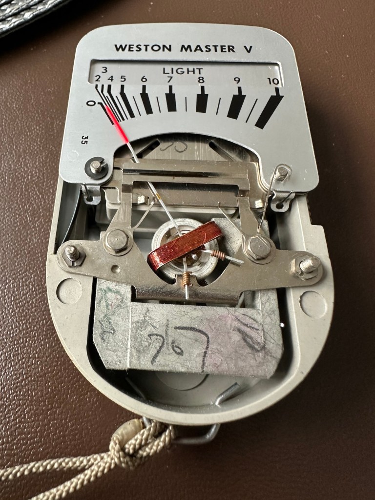
The calculator panel on the front is undamaged and in full working order, the light baffle on the rear is also operating as it should and the info panel under the viewing glass changes as the baffle is operated. The pointer lock is operating as is the fine tuning screw on the rear.
Baffle closedBaffle open
There is a very slight movement when exposed to intense sunlight with the baffle open or closed however it is only very slight. It struggles to move past the zero indicator on the scale, hence as described it is safe to say that it is not operating as it should. We will have to look inside to see if there are any obvious issues, however I strongly suspect it is related to the Selenium cell. I would like to see if we can get this operating, I’m not overly worried about its accuracy as I’d just like to see it move through its entire range. It would be good to see if it is at all possible to revive a “dead” light meter. We can only learn from dismantling and investigating such items.
Repair:
I’ve left the unit in sunlight for a few days, as this has been known in some rare cases to just kick start it back into life. That doesn’t seem to have worked in this case so let’s have a look inside.
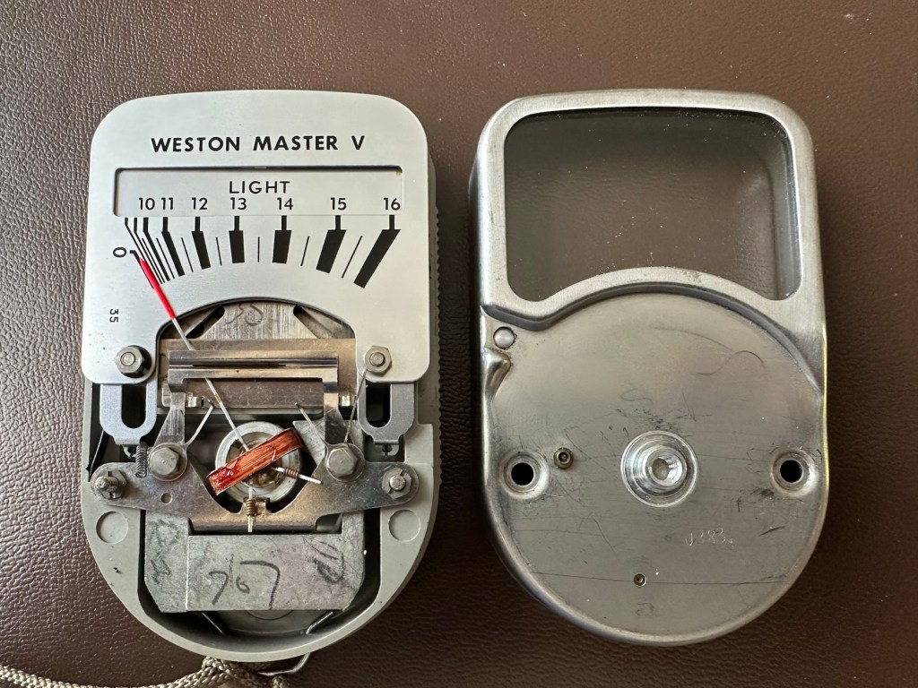
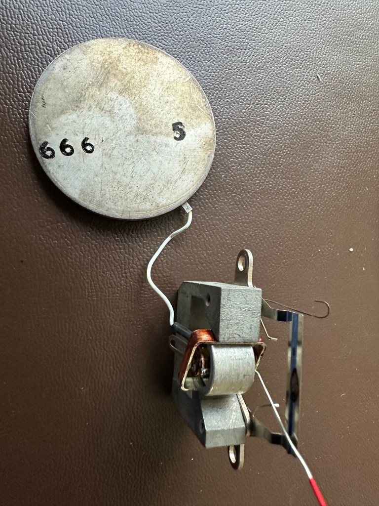
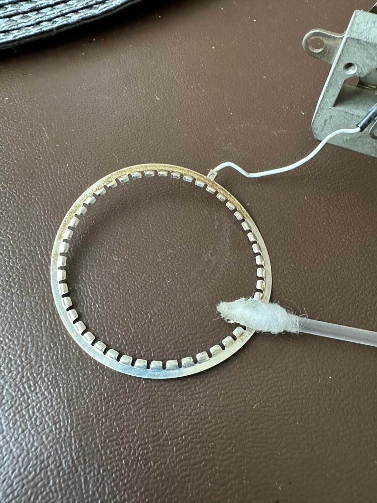
Remove securing thumb screwRemove two nuts Case lid lifts offCarefully remove fascia platesRemove sliding needle lift mechanism and expose selenium cellCell, armature ring and ammeter coil removedCell connecting ring cleanedCell contact ring, cleaned and renewed
The whole unit came apart quite easily to expose the selenium cell deep in its workings. Using a multimeter on the cell, indicated life in the item as values changed as the cell was moved from the dark into the light and vice versa so I am confident there is some life still present in this cell, but is it sufficient to power the meter? I have then used the lowest Ohms setting available and put the negative lead on the magnetic case (Ground) of the ammeter coil and the positive lead on the wire connected to it and there is no movement at all. This indicates to me that the ammeter coil is at fault and unresponsive to any voltage, I believe this is the problem and at this point the repair is not possible. I have cleaned the cell connecting ring to the point that it is now shining and free of any age related contamination. The contact ring on the cell itself I have revitalised with a metallic silver pen. I have checked continuity and that is also good and acceptable. One thing I did not see in this model was the use of a resistor that is used in most selenium cell light meters between the cell and the ammeter coil, maybe there was never one used within this range of meters, I’ll have to check that out. I have checked this out via numerous sources and it appears the Weston light meters never had a resistor placed in line at any point, so that has cleared that question up. This unit is dead due to a faulty ammeter coil.
Result:
The unit is cosmetically very good and I believe the actual selenium cell is functioning but at an exceptionally low level. The tests on the meter ammeter coil have come back negative indicating that there is no life in this part of the meter. I suspect the fine wires on the coil are possibly damaged. The only way I can get a working unit would probably be to obtain another faulty unit to transplant parts, I may well do that in a later post.
I hate not getting the fix done, however this unit is in excess of 50 years old and to be honest the odds were stacked against me from the start. I did state that I may actually mount this item in a frame as a photographic art piece, that may still happen but I’d love to prove the original cell is still functional if I can. Maybe I just might buy a donor unit to test my theory on.
I’ve learned a lot from this post on the repair and dismantling of these units so that is a big positive. Knowledge is always king as they say.
It will not go to landfill. It will be reused in some form, you may even yet see a follow up post regarding it.
Thanks for passing by, it is always very much appreciated.


You must be logged in to post a comment.