

I’ve just purchased three of these cameras for a total of £24:98GBP. All non working of course but when healthy they normally command a price around £35:00GBP each. Here is what the listing said for each one:
Camera one:
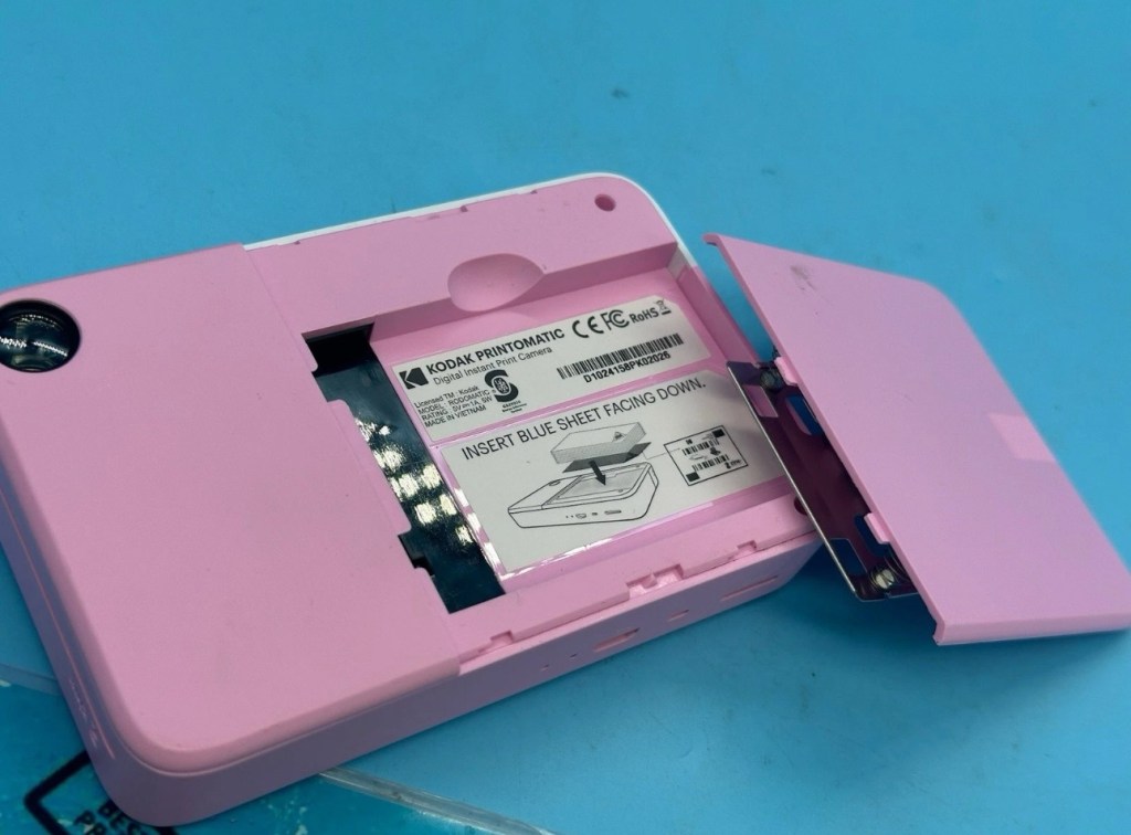
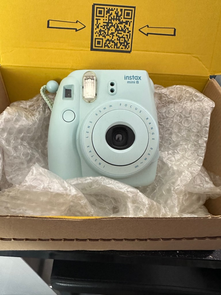
Kodak Printomatic Digital Instant Print Camera
Camera does not print
Can be repaired or used for parts
EBay
Camera two:
Camera is in good cosmetic condition.
Camera doesn’t charge. Battery charging light flashes but it doesn’t hold battery.
It hasn’t been tested further.
EBay
Camera three:


Please look at the photos carefully, as they make up the majority of the description.
It has two faults
The springs on the back are broken, meaning the rear metal plate is bent , and it often doesn’t push photo paper through correctly.
The shutter button is also depressed.
EBay
This third one might be a longer term repair as I’ve never known a quick fix for a depressed button, that requires a psychiatrist… (That’s me just trying to be humorous, I’ll grab my coat and leave now 😂🤦♂️)
To be honest the issue with the third camera seems to be a regular problem based around the design of this camera. Too much pressure on the button normally results in the switch inside detaching from the main board, it’s poorly positioned at an angle and usually not soldered in place too well. The springs should be an easy fix.
I’ve brought these cameras from three different sellers. if I’m lucky I’ll be able to get all three up and running, worst case scenario is that I use one for spares and have two good working examples.
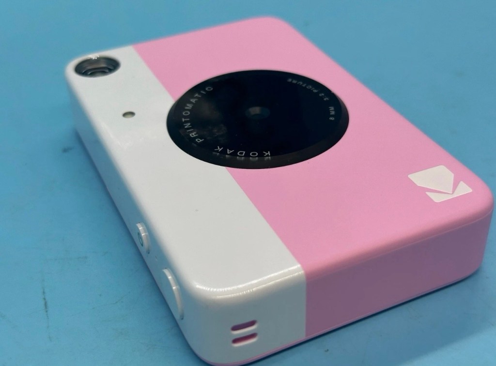
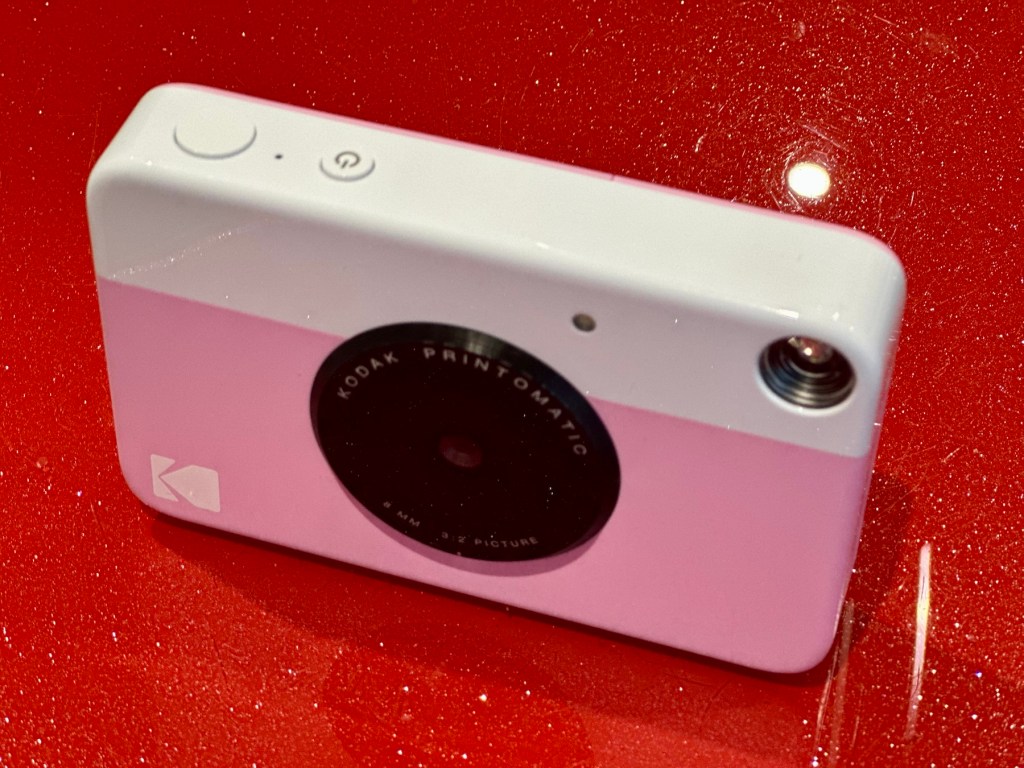
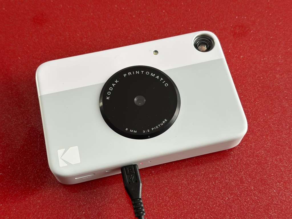
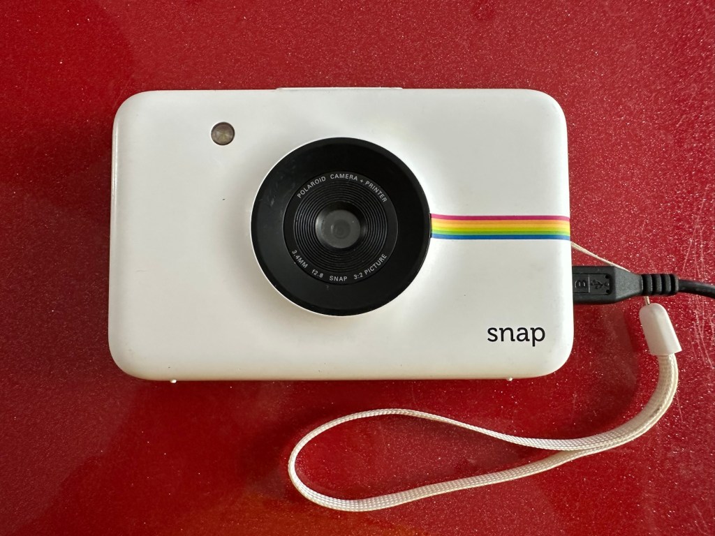
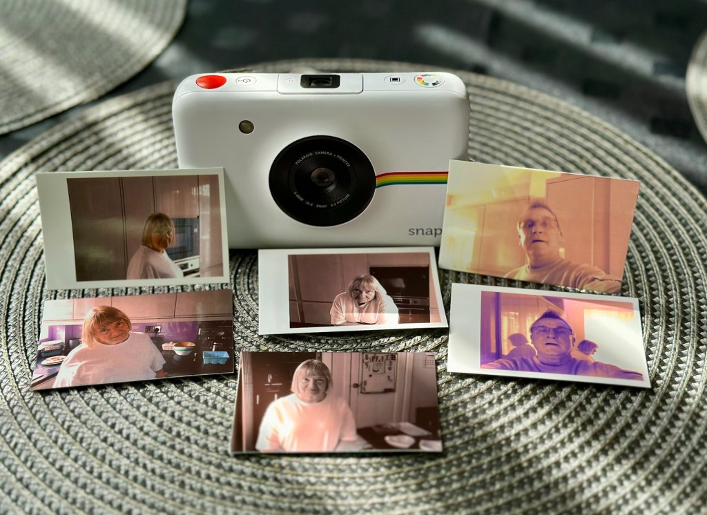
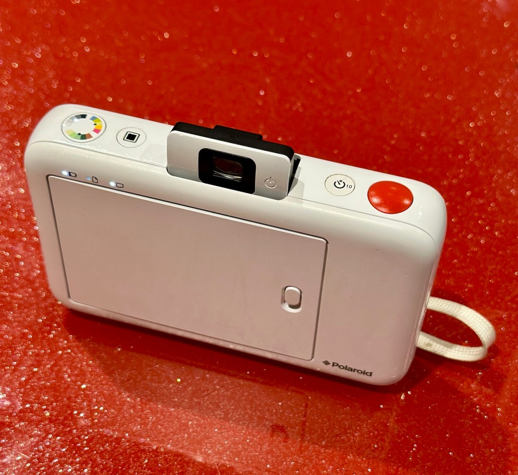
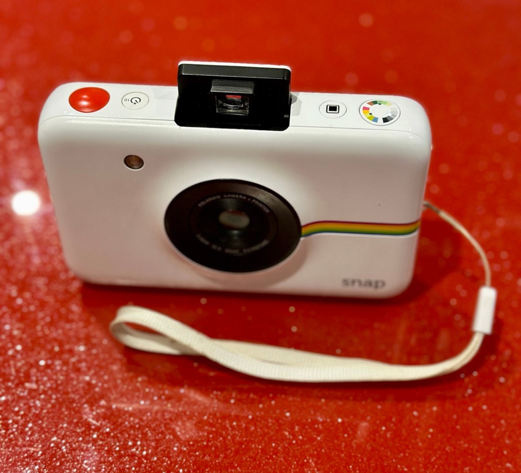
Anyway I’ll just have to wait for their arrival to assess them all, and decide what repairs are required. In the meantime here’s a little bit about these cameras that are again very similar to the Polaroid “Snap” camera range, that also use zink paper. And seeing what is quoted below, the Polaroid “Snap” and this Kodak Printomatic are in all aspects one and the same camera.
Well, since Kodak doesn’t really make its own consumer cameras anymore, the Printomatic is actually being produced by a company called C+A Global, which is just licensing the Kodak name and branding. C+A also licenses Polaroid, and was behind the two-year-old Snap. Both cameras were designed by Silicon Valley firm Ammunition Group, which confirmed to The Verge that the Printomatic is basically the same camera as the Snap, though simplified and rebadged. (The cherry on top of this corporate synergy sundae is that C+A also works with Zink.)
Released 2017
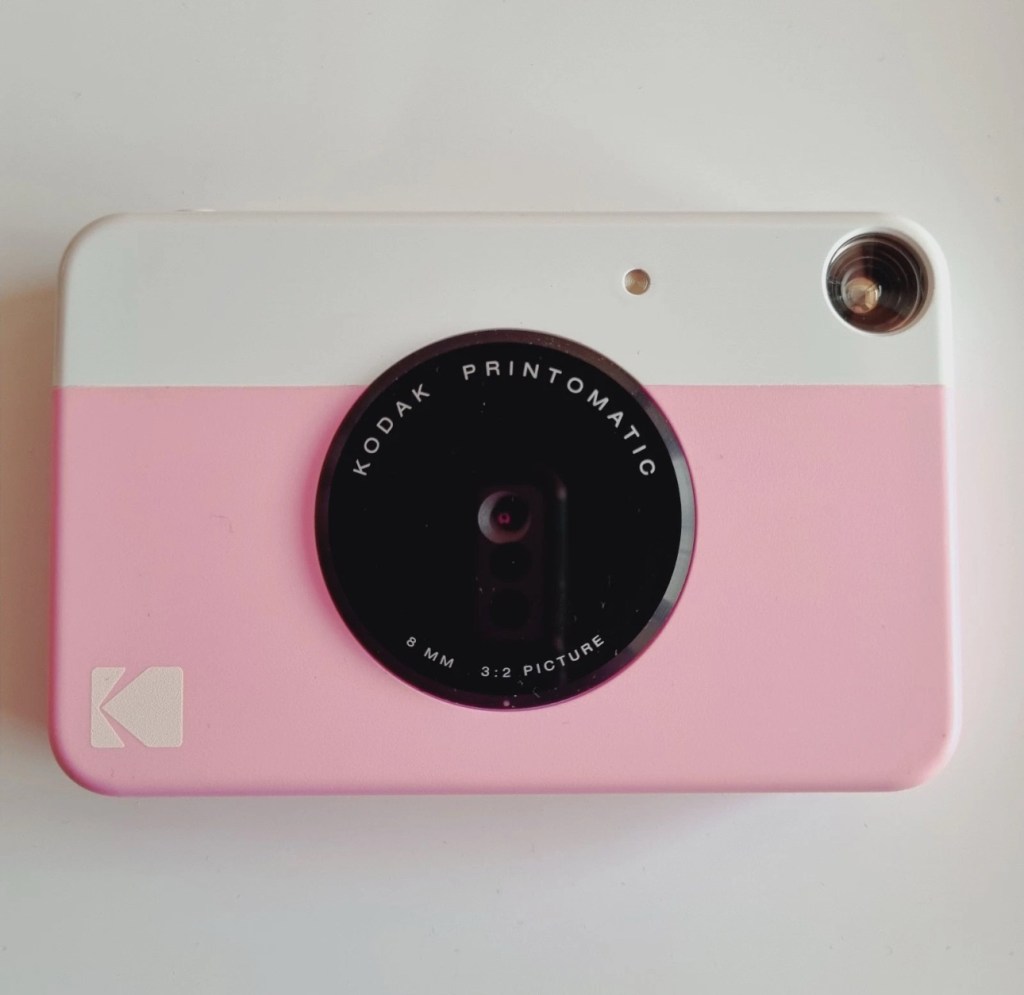
The PRINTOMATIC camera instantly and automatically prints high-quality, full color photos with point-and-shoot ease. It uses KODAK ZINK Photo Paper, so no ink cartridges or toners are needed. The photo prints are durable, water resistant, and adhesive backed for extra fun. The camera’s speed allows you to shoot a new photo while printing the previous shot. The KODAK PRINTOMATIC is fast, fun, and easy to use.
Features
- 5MP image sensor
- Prints automatically when image is captured
- Vibrant 2″ x 3″ photo prints are durable, water resistant, and adhesive backed
- Built-in flash
- Optical viewfinder
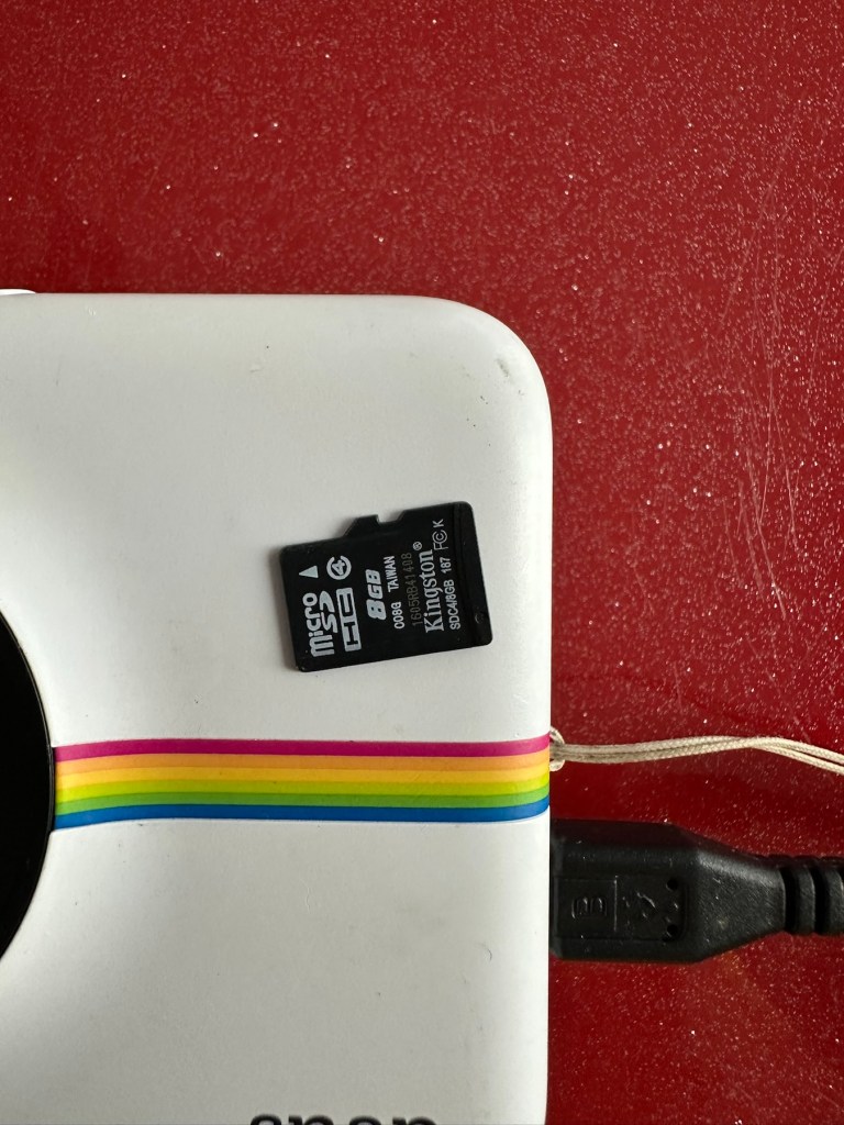
- microSD™ card slot
Kodak Ltd & The Verge
The reviews all vary, from very good to downright diabolical, I’m not really surprised since Kodak “Hoared” out its brand name to the lowest bidder many years ago. Am I bitter? A little, as I used to work for Kodak in the days when they were a world leader, the mistakes they made, the decisions and leadership were absolutely awful. And the fact that their demise has lowered my pension pot by about 40% due to their financial mismanagement is another axe that I regularly grind. Yes I am bitter, and since I’ve recently repaired and reviewed their competitors cameras I thought I’d give these a try. Will I be impressed or disappointed? Who knows but I do have an inkling on which way this may swing. But for what I’ve paid for three cameras I’m not really that fussed, it’s just pocket money.
Assessment:
Camera one:
Apparently doesn’t print. Well I’ve put a couple of sheets of Zink paper inside and two pictures were produced. The sd card slot is fine, the charging port is in good condition. Transport is working perfectly. It certainly does print. Just needs a bit of a clean. To be totally honest there is nothing wrong with this camera and for an outlay of £8:00GBP in total I have a working bargain. Kerching – a rare EBay win.


Nothing more to do on this one. So on to camera two.
Camera two:
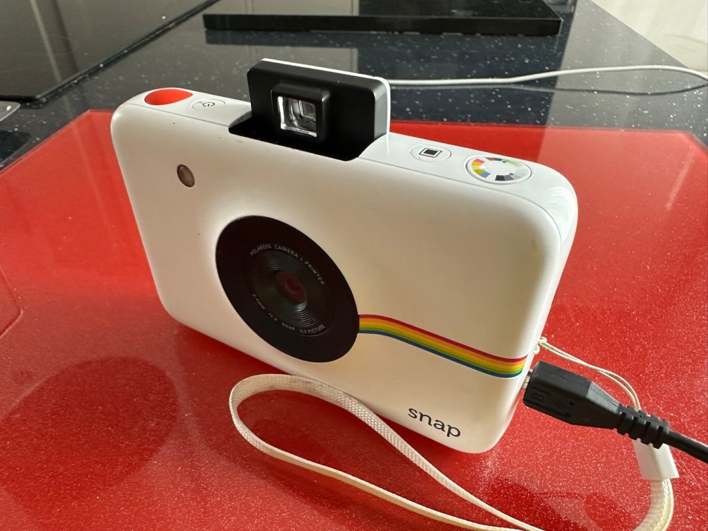
It’s a bit grubby cosmetically but nothing that a light clean wouldn’t sort. This particular one cost £8:99GBP all in. It was dead on arrival so I’ve checked that the charging port was ok, and then put it straight on charge.
I’ve also given it a light clean whilst charging and the overall appearance has greatly improved. I must just be patient and wait and see if the unit does take a charge, or the original fault appears.
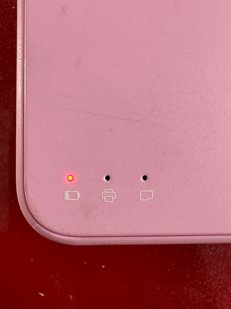
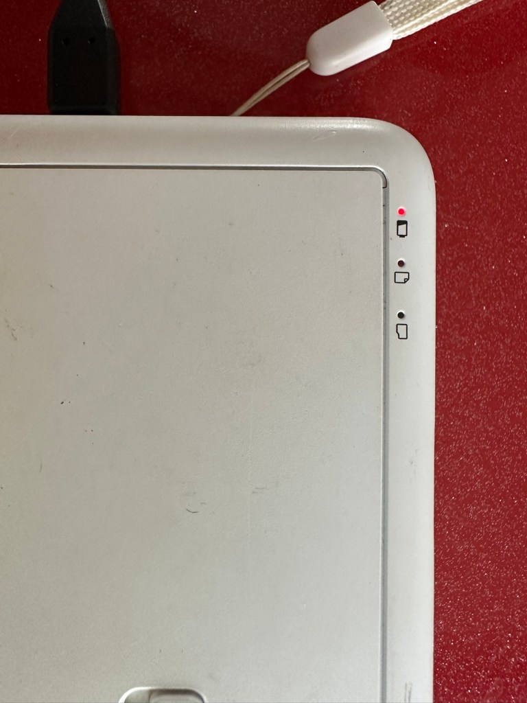
Whilst on charge the originally mentioned fault appears. The charging light was showing a steady red, it is now a rapidly flashing white light with the occasional steady red indication for all of a few seconds and then it’s back to the rapid white indication and it then all repeats. I’ll leave it for a while to see if there is an improvement, the battery just might be so dead that the inbuilt battery management system may just well be refusing to cooperate.the on/off button on the front doesn’t work as well, this might be also related to the battery issue.
Camera three:
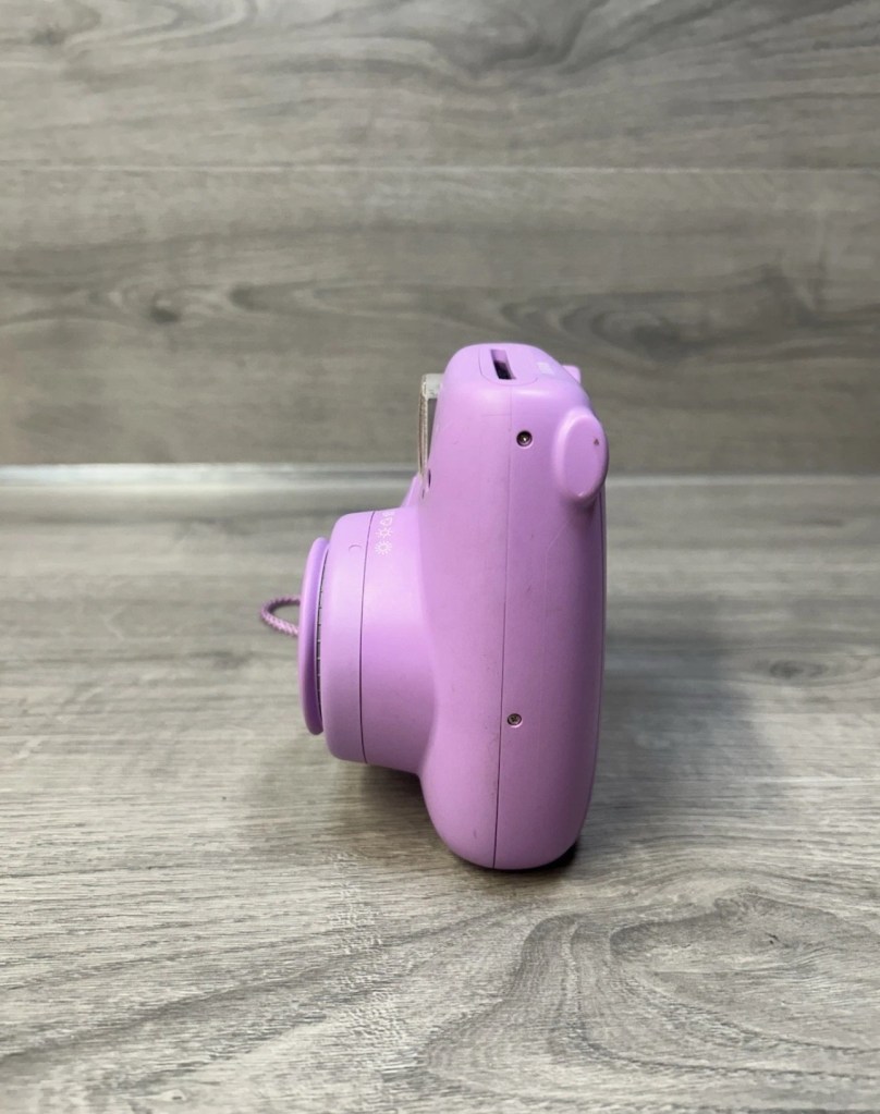
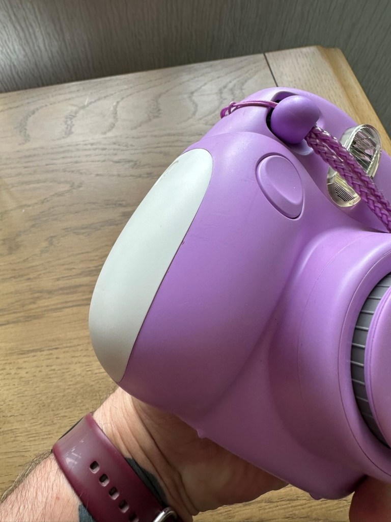
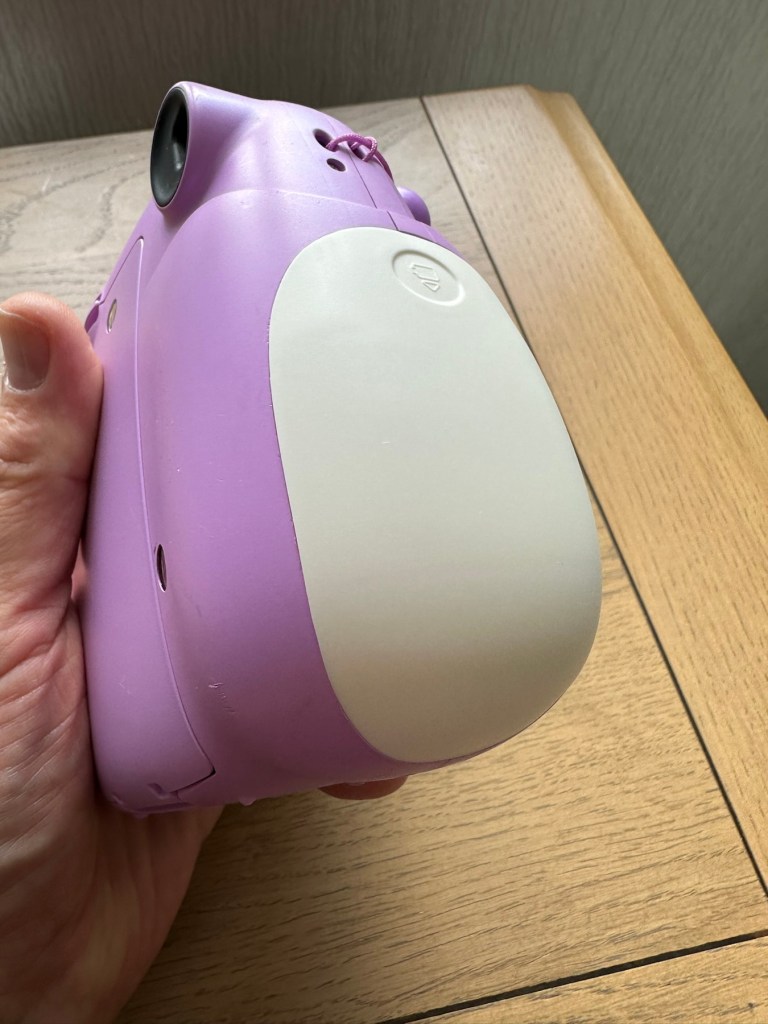
Looking very nice and cosmetically very clean.
This one cost £7:99GBP all in. This one is reported to have two issues, a damaged paper pressure pad and a button stuck in the depressed position.

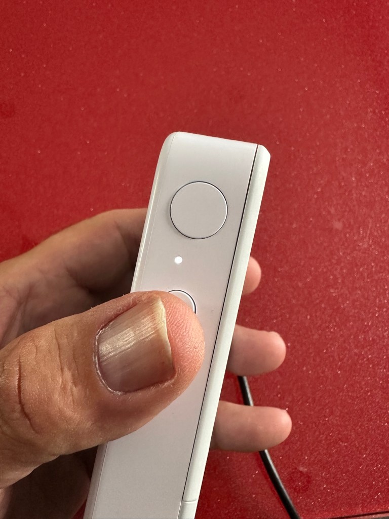
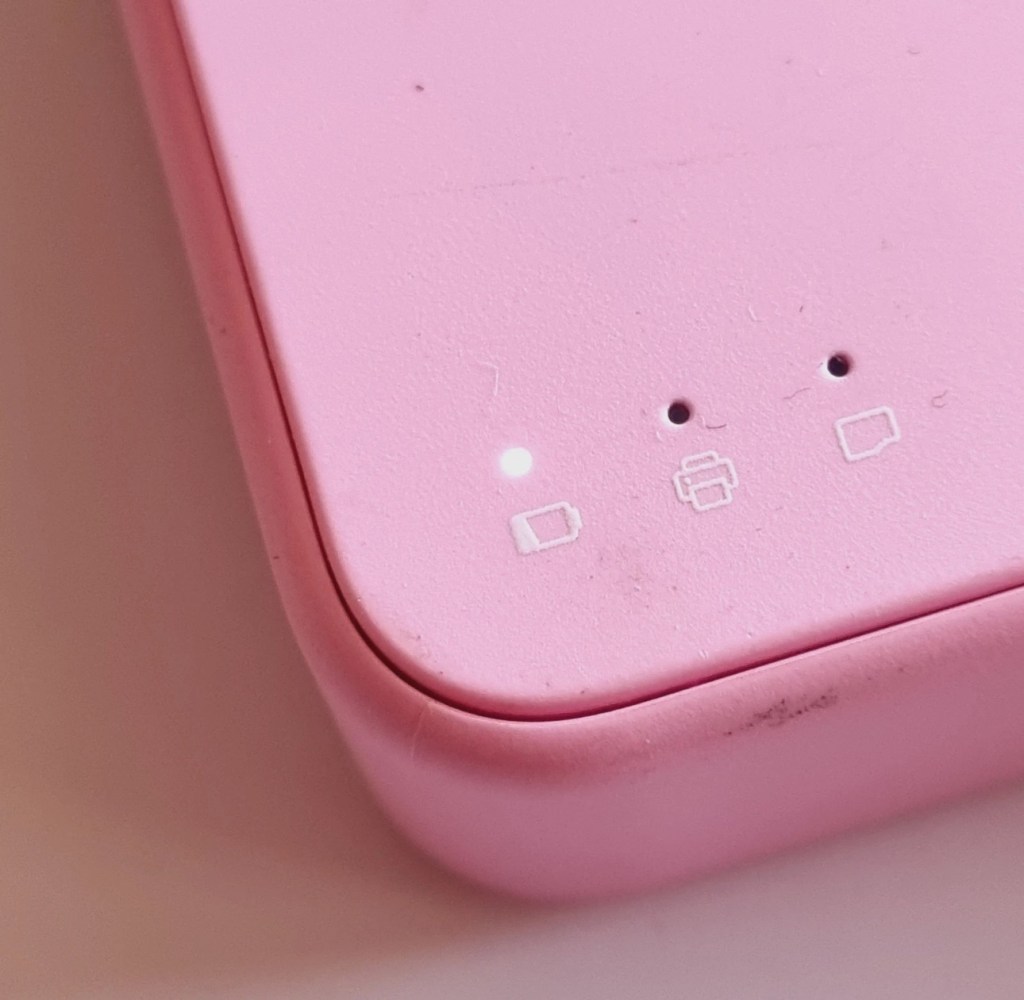
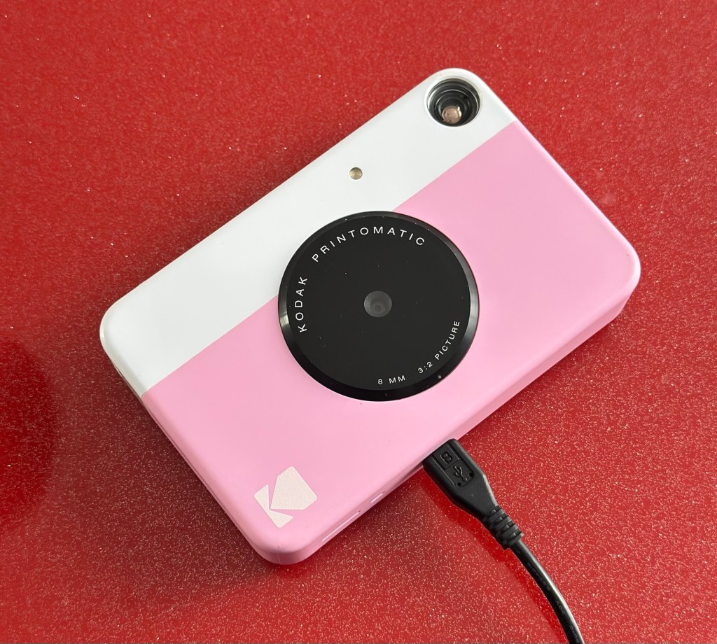
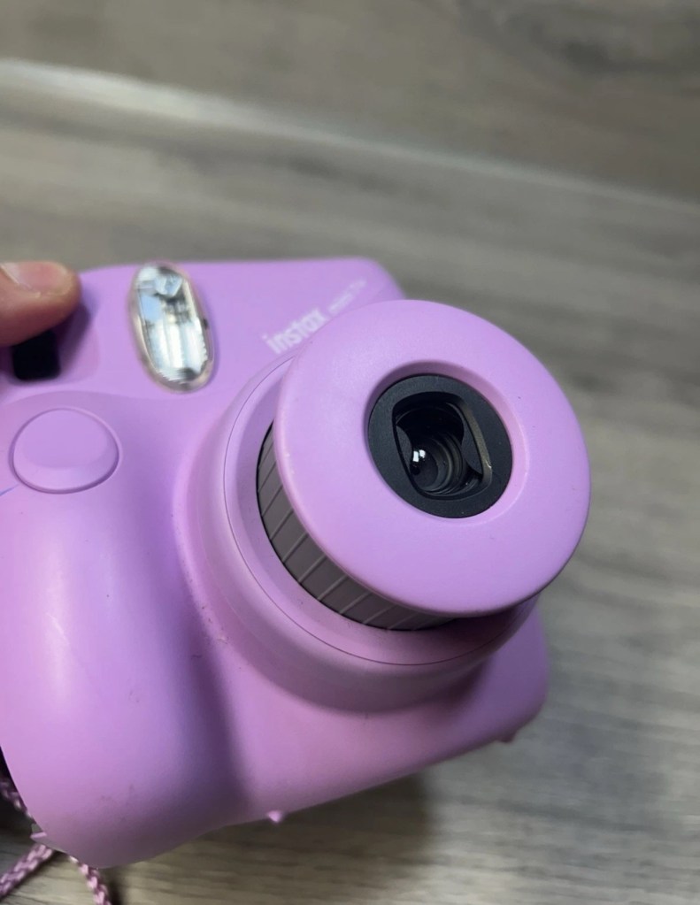
But first I’ve put it on charge to see that it charges, I’m pleased to report that everything is alright in that aspect, and I’m pleased to say it charged fully with the correct lights illuminated. The white light on the top by the exposure button is flashing as a result of the button being stuck in the depressed position, I believe.


This one will need the paper pressure pad repairing as well as the button that is stuck in the depressed position.
Repair:
Camera one:
See above. No repair required. Just a light clean and some TLC. Why did they sell it as damaged? Who knows just what goes on, in the mind of an EBay seller.
Camera two:
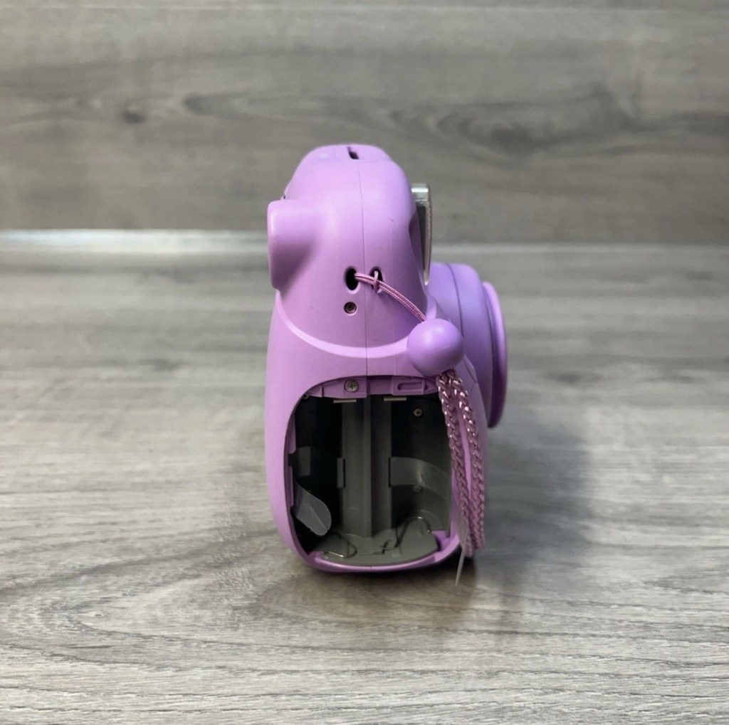
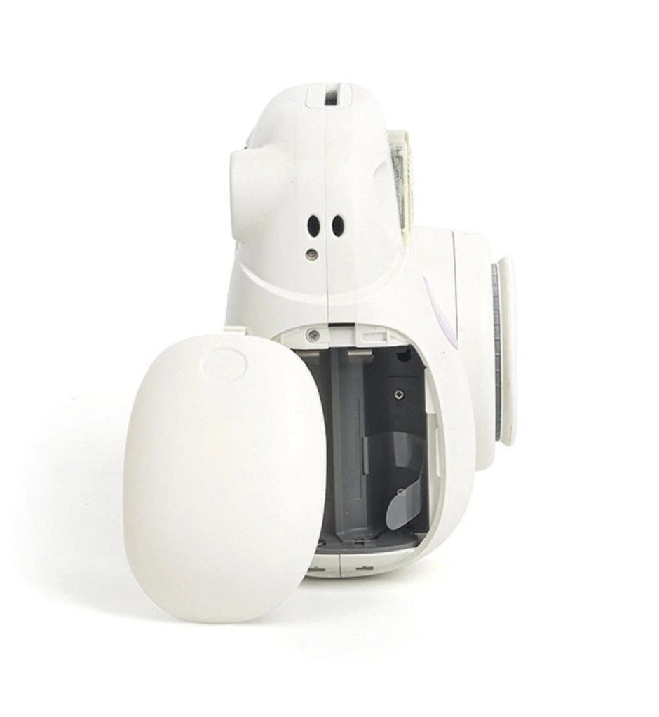
This will need to be opened to get near the battery. We may well be able to get the battery to accept a small charge and this may be just enough to fool the battery management system in the camera to take over and continue charging.

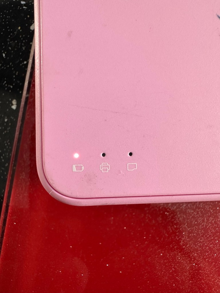
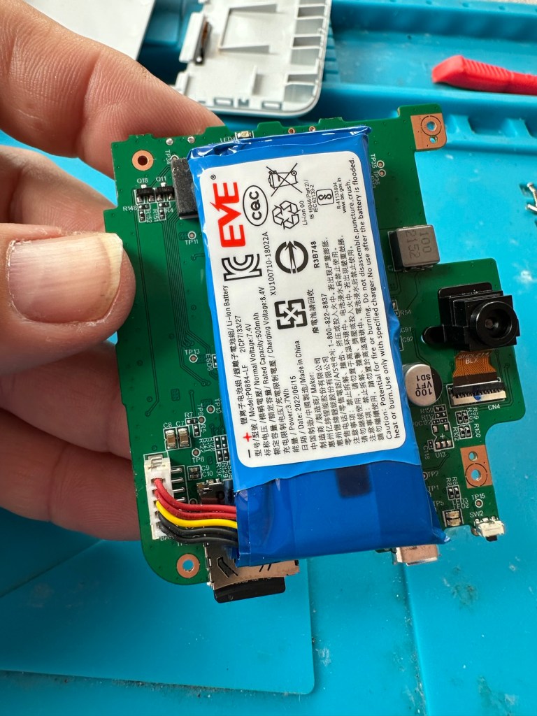
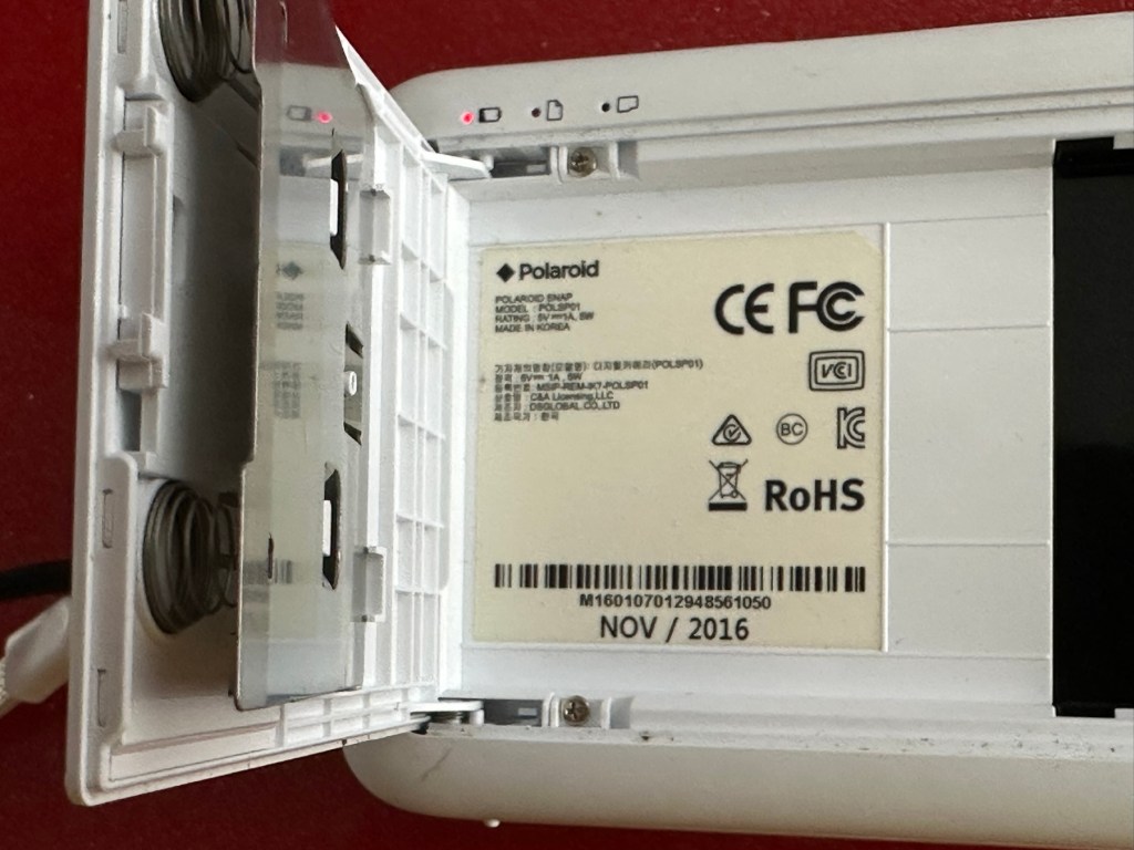
Cover off I’ve checked the battery readings and it’s reading a healthy 6.5v and as it’s a 7.5v rated battery I believe this to be healthy, it holds a steady charge the battery is fine. Looking at the led lights they are capable of two indications, red or white and that’s it. I believe the charging light flashes when it’s charged as it cannot possibly show a green light as there isn’t one. This is confusing as normally a flashing white/red light normally indicates that the battery needs charging. Everything that is happening goes against what the producer has published regarding the led indications. But I am convinced the battery is good despite it not turning on. Hold on, I think I’ve found out the problem here…..

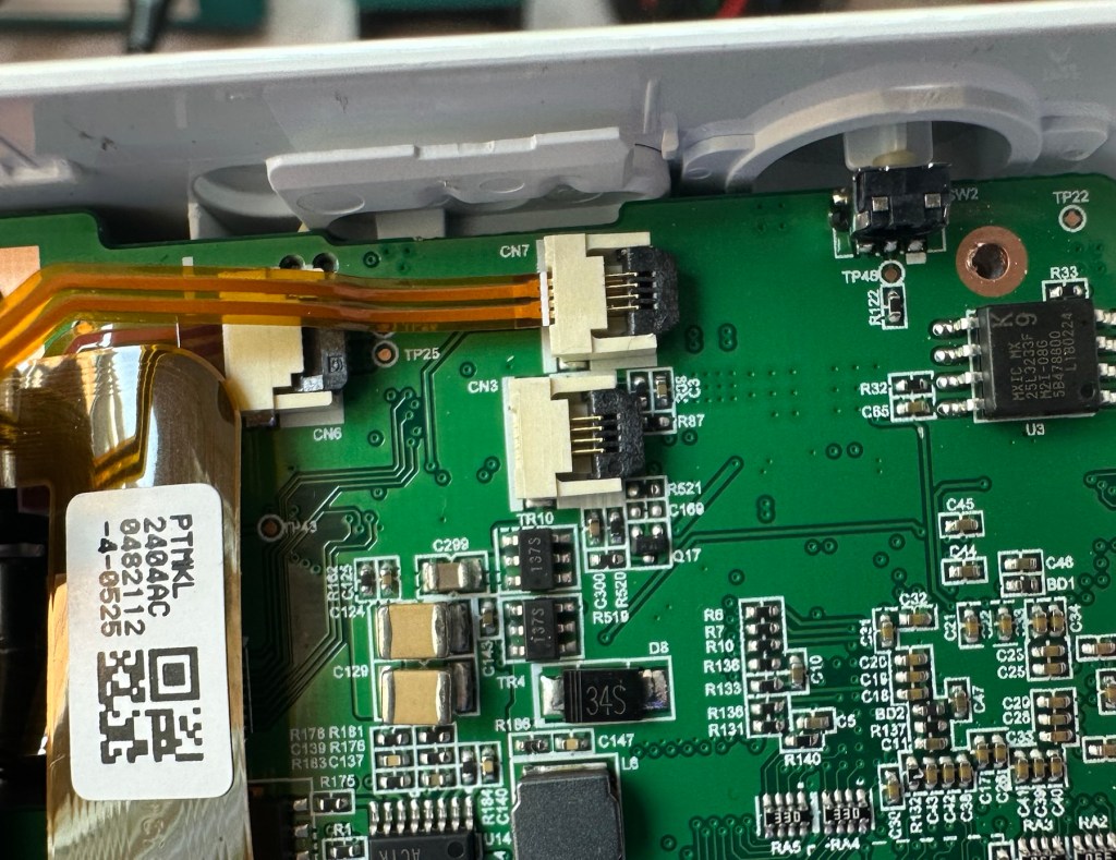
On off button ribbon connector was not in place
It appears that someone has been here before me or that the on/off button ribbon connector has disconnected itself over time. Either way it’s not where it should be. I’ve put the connector back in place and secured it. I now have power and control of the camera.
All lights working, transport whirring away let’s put some paper in to give it a try.

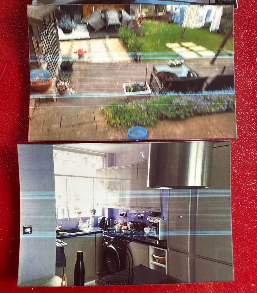
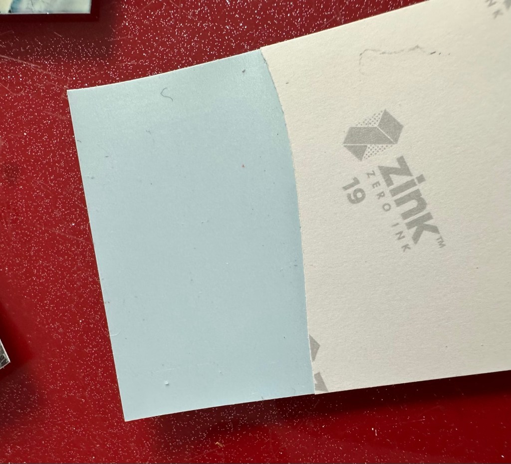
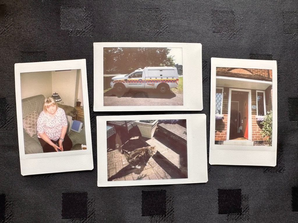
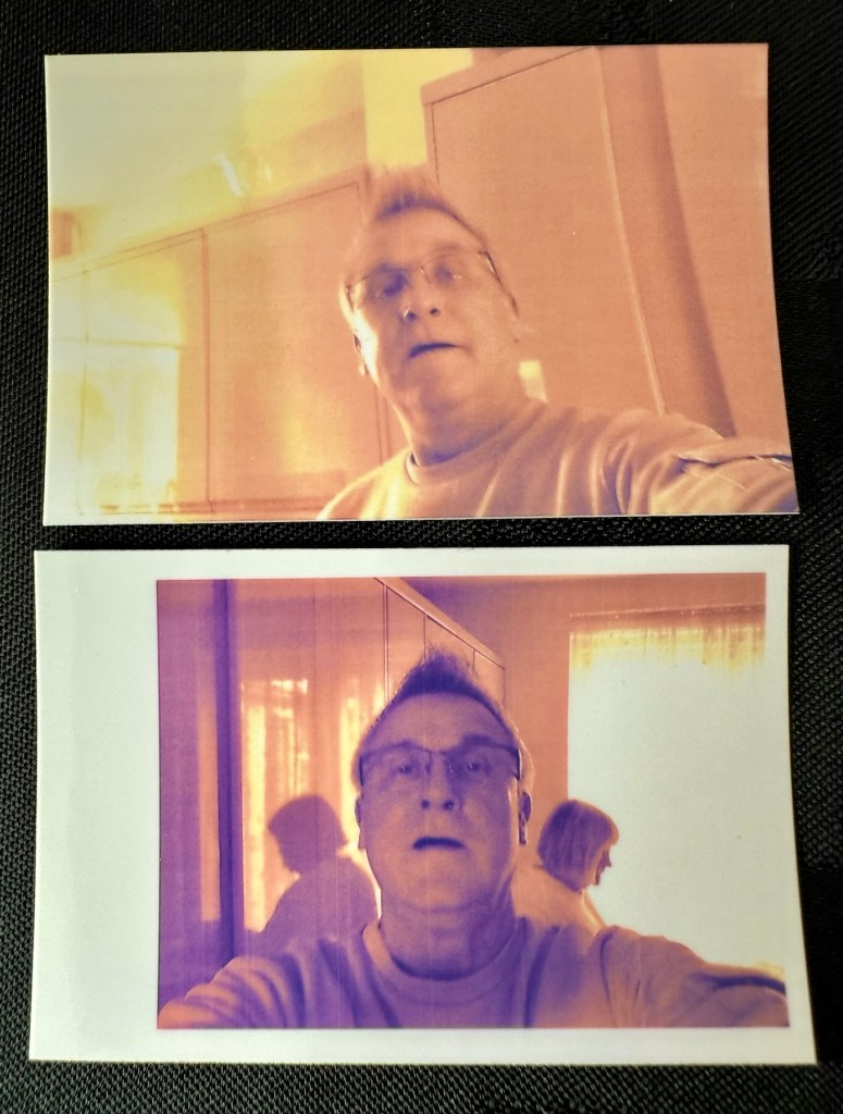
Well it prints ok, all pictures appear to have a “blue tint” to them, however there are big tramlines across the print as you can see, this indicates a dirty roller. What I’m going to do here is peel half the backing of a sheet of Zink paper as the back is adhesive allowing you to stick photos on whatever takes your fancy. By running a half sheet of exposed adhesive, upside down through the camera with the adhesive being the trailing edge, it should allow any debris and dirt to be collected on its way through. I will do this three or four times and even though I will no doubt get error lights appear I can just reset the camera with no further issues.
And that worked. The tramlines have gone.

I’ve also tried the black and white mode as you can see above. I’m very confident, in fact I am positive this camera is now working as it should. I have also put an sd card in the base and all pictures are being recorded as expected. A quick clean and we now have a perfectly good working example of this camera. Let’s move on to camera three.
Camera three:
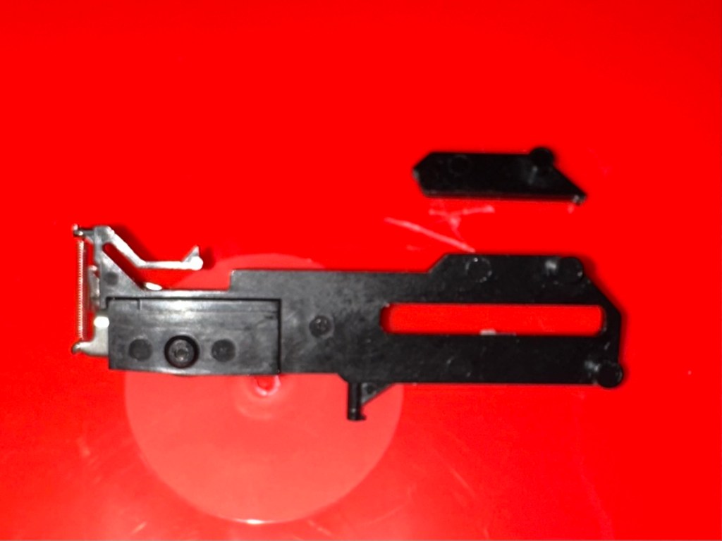
We have to open up the camera to get to the issue with the button.
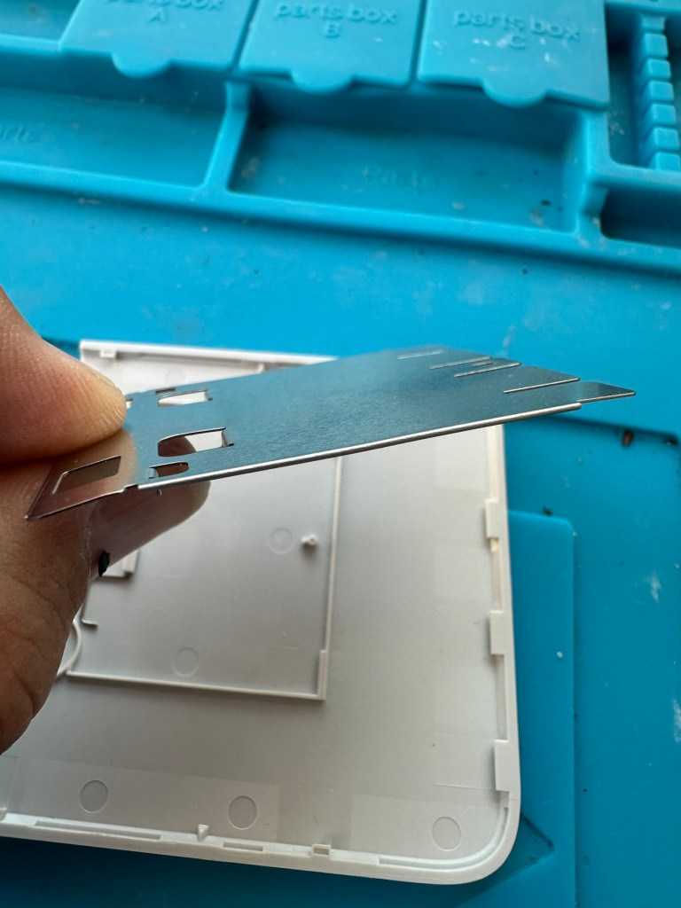
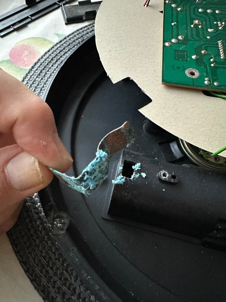
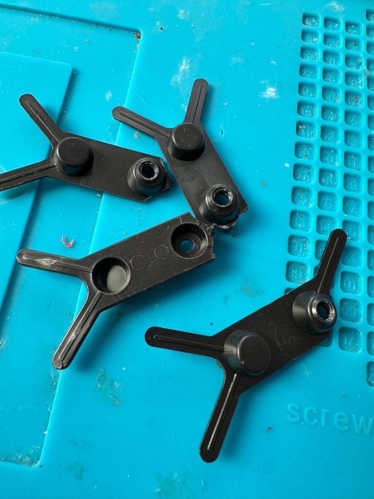
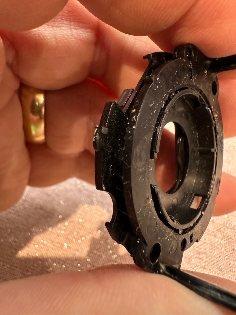
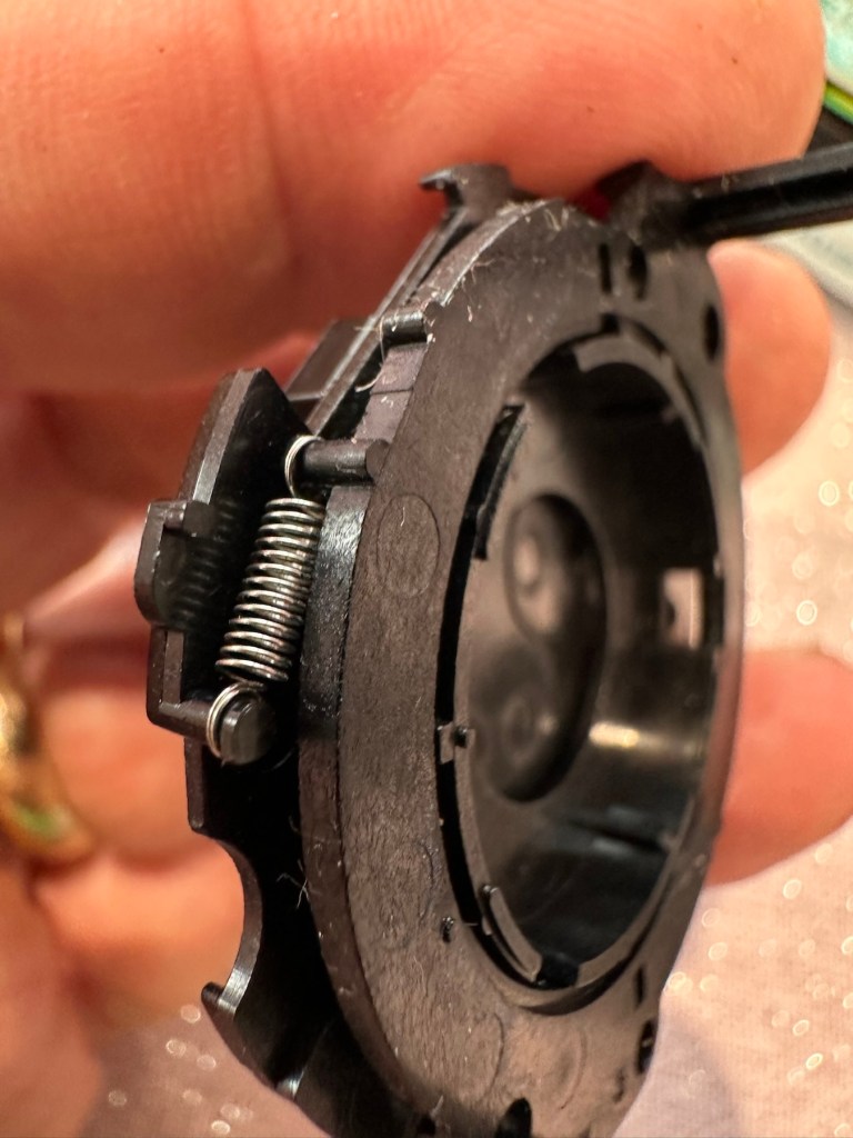
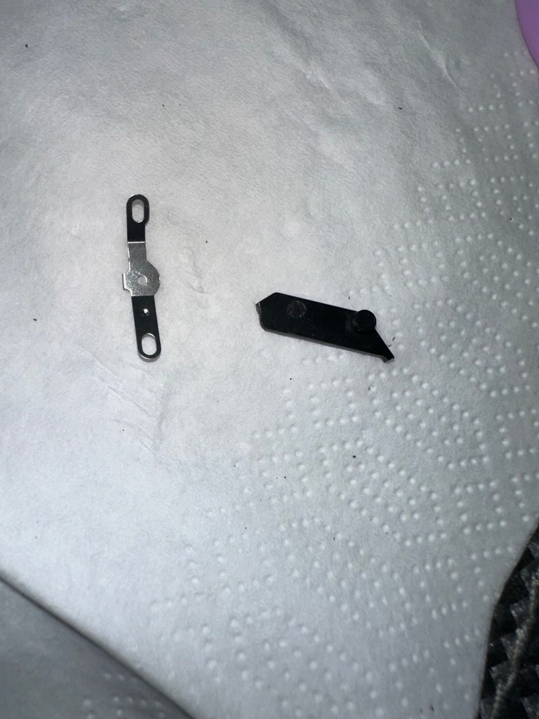
The paper pressure pad needs to be dismantled, straightened up and two compatible springs need to be found to keep the required pressure in place on the paper pad. I’ve dismantled the pressure pad and straightened it out, just needs a couple of springs to complete, I’ll sort these out later.


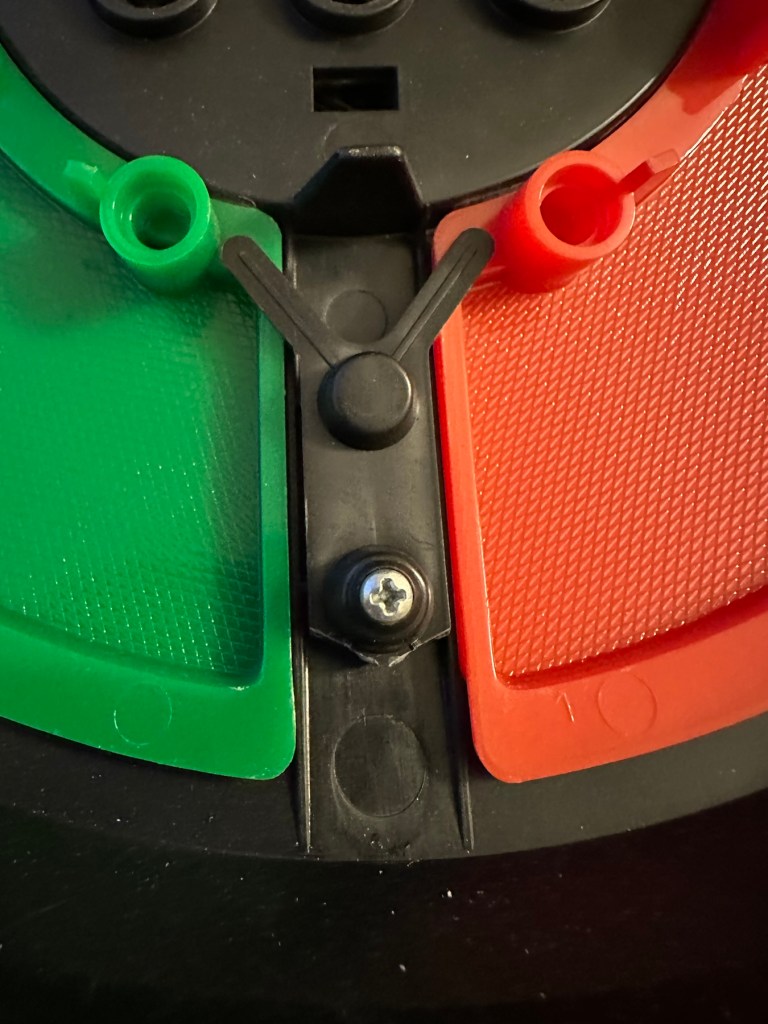
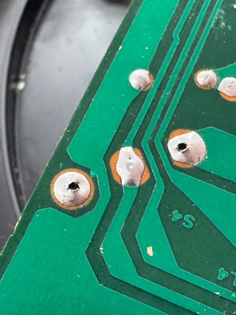
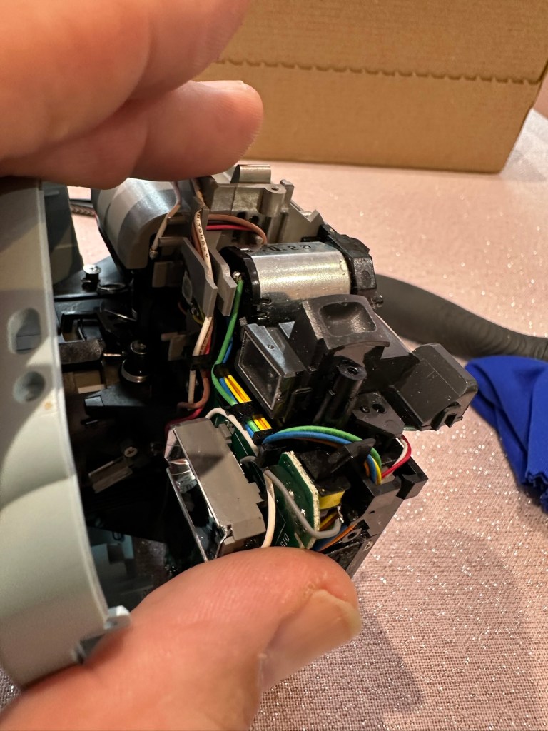
On opening the camera it was as clear as day that the depressed button was as I first thought, the three solder points below it had come loose, no longer making contact.


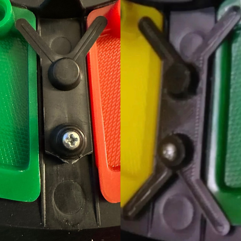
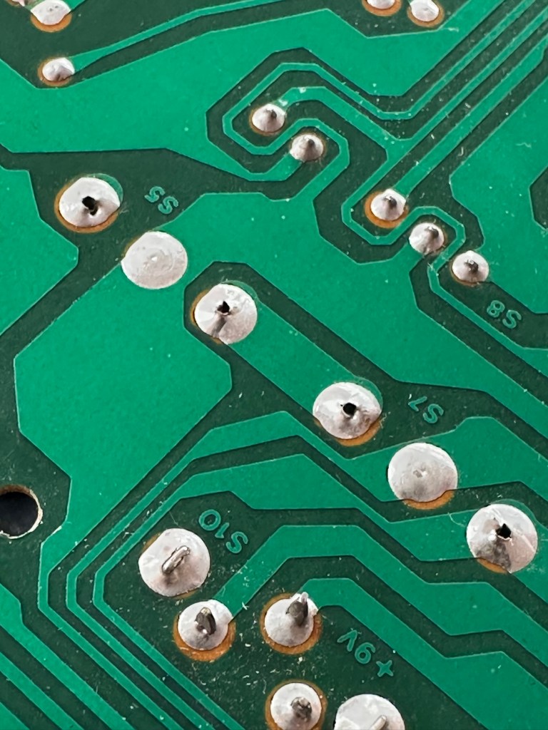
It’s plain to see in the pictures above that the button that is damaged has all three points of contact broken. these need re soldering to strengthen them. You can see this issue in the microscope pictures I took below.

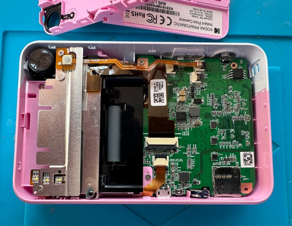
The switch has been tested and it clicks and operates as expected, this is a known weak point with these cameras and a design fault as well, although the manufacturer would probably deny this. It’s a given fact that the manufacturer wants to sell as many as these units cheaply to the throw away consumer, you only have to look at the main board below to see this…
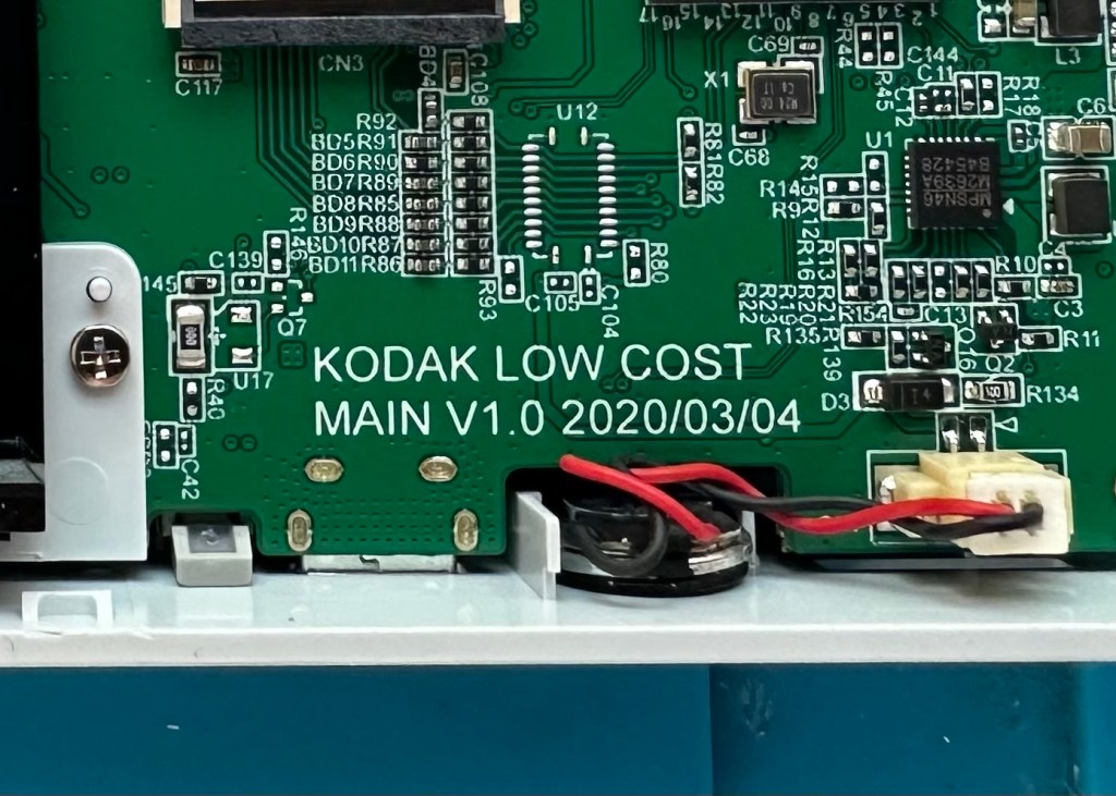
It really saddens me to see the levels the Kodak name has sunk to, these units are just replicas of the Polaroid touch/snap range, but even at this stage in the repair the Polaroid versions are far superior. Quality control and the cheap design of these Kodak units is borderline awful.
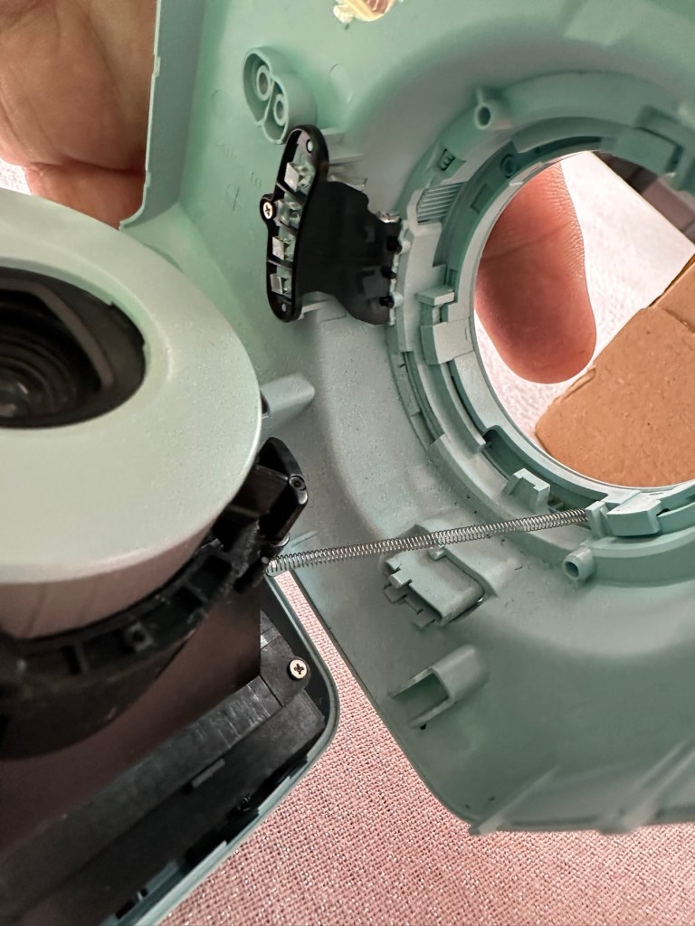
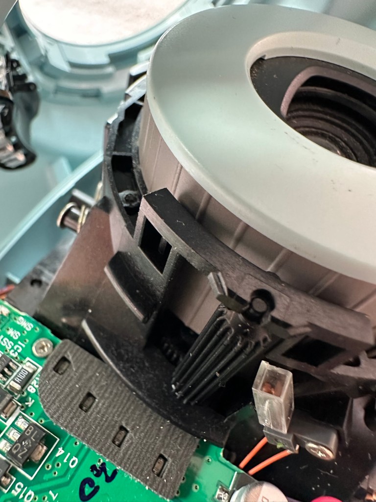
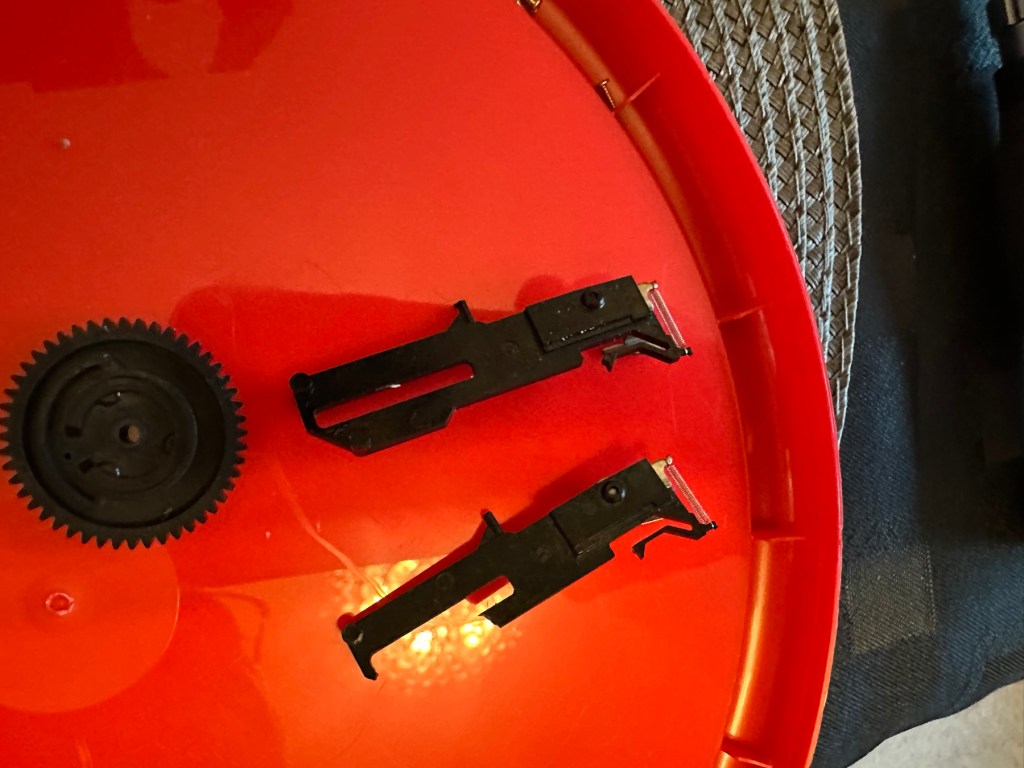
This unit is proving to be a right pain in the ass. The original fault with the exposure button has been repaired and the paper pressure pad is all but repaired, but it seems that being hidden by these two faults is a totally different issue. I have had this camera completely dismantled and have also separated the printer from the motherboard, but this issue of the permanently flashing white light still exists, so the fault is definitely only being carried on the motherboard.


I’ve checked the motherboard thoroughly using my microscope and there is nothing glaringly obvious at fault. I have checked for shorts on the board of which there are none. The only issue I found was that the lens ribbon cable was sitting off centre, however I corrected this but the flashing light issue still remains.
There are two faults that are connected with this flashing white light. One is that the light occurs whilst printing, this is not the case with this unit as it even occurs as stated with the printer disconnected. The other possibility is that it flashes when doing a firmware update, I have attempted to update with the latest firmware and the only difference is that I cannot turn the lights or camera off at all, I have to crash it by removing the battery.
It’s looking as if this could be the issue. The previous owner has probably bricked the unit by interrupting a firmware update and it has corrupted the system. I’m going to have one more attempt at updating the camera with a clean unused sd card to see if there is any possibility of recovery. If this cannot be done then this unit will become a spares unit that to be honest I’d rather not have as I don’t really want to purchase any more of these cameras. But you never know, someone may want one repairing.
Result:
Well in the wise old words of Meatloaf, I guess “Two out of three ain’t bad”. The grey one is bricked, as after numerous attempts of updating the firmware it just isn’t having it. It is just a brick. However there are numerous spare parts that can be used including a good battery, lens mechanism and a number of other pieces. I just didn’t want that though as i don’t really see myself going out of the way to obtain another one, they are as cheap and nasty as you could possibly find. The Polaroid versions are of a far better quality in my opinion, and they are hardly high class.

The positive here is that 3 cameras, quite obviously built for the throwaway generation have been saved from landfill and can be used again. What I’m going to do with the two I have is probably put them both back on to eBay to recover my out goings. If not, I will pass them onto our local hospice to sell on.
Been an interesting fix, but I’m not venturing back to these Kodak models anytime soon.
Thanks for passing by. Always appreciated.


You must be logged in to post a comment.