Straight to the point. I think it doesn’t work. 🤷♂️
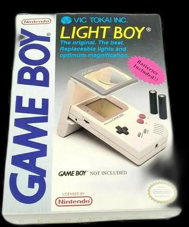
The original Light Boy
My original Light boy, for the Nintendo Game boy
Ive got a Game boy, I love it. However the biggest issue has always been as soon as it goes dark you’re stuffed. As the screen was never back lit you either had to tape a torch to your head or sit under a bright light. The Nintendo Light Boy went a little way to eliminating the need for the torch by incorporating a light and a magnifier within a unit that connected to the console.
This one doesn’t work though, which is good for this blog. I paid a good price of £14:95GBP considering original ones like this are selling between £40-£90GBP. There are cheaper alternatives, but hey, why?
Shouldn’t be the hardest fix I’ve ever attempted, but it will be a great addition to my Game Boy collection.
Assessment:
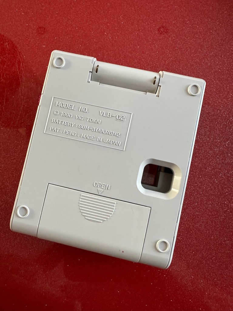
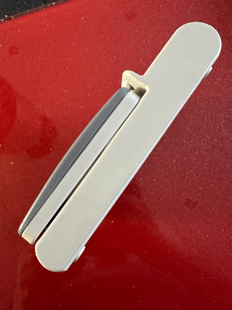
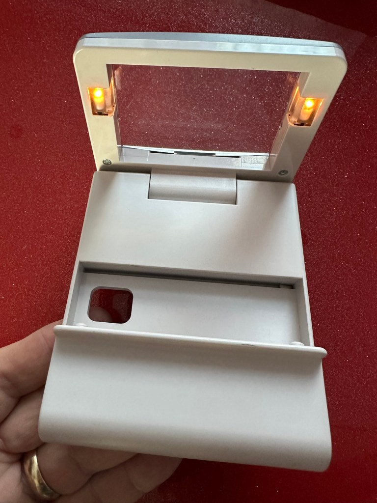
The unit has arrived and is in a very good cosmetic condition with only a few slight scuffs and marks that should polish out. Two AA batteries have been put in and switched on and true to the description in the sale, it doesn’t illuminate. Glass lens is in good condition and the screen folds as it should.
Looks tidy, just light not workingSome small marks. Nothing too bad or permanent
Repair:
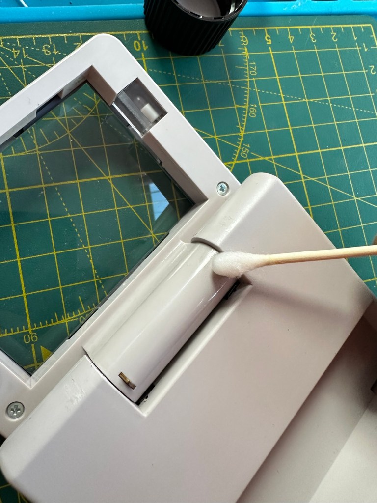
This is a really simple circuit to be honest. Two batteries, two lights and a switch. That’s about it. The screen pivots and on here there are two teeth that make a contact with two small plates on the main unit when the screen is at 90 degrees to the console. When the switch is on, the lights should illuminate at this angle, and when closed contact will be lost and the lights extinguish.
Teeth on the screen hingeTeeth connection with plate turning on lights.
When I put batteries in there was a very dim intermittent flicker, aha I thought, dirty contacts and they sure were.
I cleaned the switch and the contacts using some IPA and removed a fair amount of old dirt from the contacts. The switch was operated 30 or 40 times to really get to anything that was deep in the switch, and this worked.
A good clean with IPA was all that was needed.
Batteries back in and unit at the correct angle, switch to the on position, and hey presto we have a constant uninterrupted supply of light.
We have light. It’s working.
The little marks and scuffs on the shell were all removed with a little cleaning solution. This item is now in a perfect state of repair and looking right handsome!
Result:
This is undoubtedly the easiest repair I have had yet but I’m not complaining. It always amazes me about the sellers on these platforms. I purchased this as spares and repairs damaged, when there was absolutely nothing wrong with it, well at least it only required a tiny bit of maintenance. They could have done this themselves and easily have charged a price at least three times what I paid for this unit. Fools 😂
All assembledWorking as intendedAll assembled, cleaned and working
Anyway their loss is my gain as they say, I now have a perfectly good item in perfect working order and now looking as good as new. And all it needed was a clean and some TLC.
Sometimes it all goes so well. Today is one of those days.
Thanks for passing by. It is always most appreciated.
It’s a process used to restore old Yellowed plastic back to its original state. Or at least it’s a way to try to. Read on and I’ll explain.
(Here is my understanding of the ABS plastic Yellowing process. There may be slight inaccuracies for which i apologise. Please do your own research on the subject. Further enquiries may be needed to satisfy your curious minds!)
Anyone who has any dealings with items built in the 80s/90s such as me will have come across an issue, especially related to anything built with ABS Plastic, and that would be the common phenomena of “Yellowing”.
If you own a game console or toy with white ABS there is the good chance that all or at least some of it will have turned a shade of yellow,
ABS plastic – otherwise technically known by its scientific name of “Acrylonitrile butadiene styrene” is a thermoplastic polymer. This means that it becomes pliable at an elevated temperature and solidifies on cooling. ABS was a flame retardant material that was regularly used as a casing for computers, gaming consoles and similar items just in case they were to overheat and catch fire. It was also used in Lego bricks for some reason, god knows how these were meant to catch fire though!
The yellowing issue lay with a chemical used in the manufacturing process called Bromine. When exposed to UV light or excessive heat this caused the photo oxidation of polymers within the chemical to break polymer chains causing the plastic to yellow and become brittle.
Come on then, tell us what retrobrighting is..
Retrobright or retr0brite as it is stylised by the guys who discovered the process, is an approach to removing yellowing from these ABS plastics, a kind of bleaching process if you like. The original recipe for Rerobright was discovered purely by chance by the CBM Museum at Wuppertal in Germany in March of 2008. I’m not going to go into the finite detail in this post, however you can read all about it here at the original Retr0brite project site: The Retr0brite Project.
The process can be a little hit and miss, however there are a lot of documented cases of it working very well. There is a downside that the yellowing can overtime return, as this process only really whitens the surface problem whilst those old polymers are still breaking down deep inside the plastic where this treatment doesn’t reach.
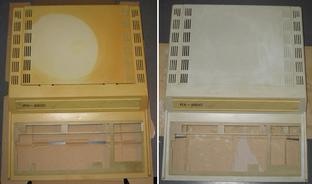
Before and after effects of this process. Pictures copyright The Retr0bight project
The process
I’m only going to touch on the process here, there are many other detailed explanations available on line, that explain the process far better than i could, here is one for example from the “How to Geek” site. How to clean old yellowed plastic on retro computers and game systems.
I will explain the process briefly below, but in no way do i accept responsibility for the way you approach the process. That is down to you entirely and i suggest you read up deeply on the subject prior to attempting this process. You have been warned!
What you need
The offending piece of plastic
Clingfilm
Paint brush or suitable application brush
Protective gloves
Eye protection
40 volume oxidising cream (Hydrogen peroxide, salon hairdresser strength.
Sunshine (Hard to find here in the UK) or a UV lamp
For starters make sure the item you want to brighten is clean. Make sure you have eye protection and gloves on as the peroxide can cause skin burns and the last place you want it is in your eyes, believe me.
Lay down some cling film. Place your subject matter on the clingfilm. Apply some cream onto the object you want to lighten and smear it around ensuring the whole item is covered in the peroxide solution, failure to do this can cause blushing and streaking. When you are happy that the subject matter is fully treated, cover the whole item in the clingfilm ensuring there are no holes where the solution can evaporate from.
Next place the item where the whitening can take place. Out in direct sunlight and leave it there for the entire day. Indoors a UV light lamp can also be used. The UV rays that originally caused the yellowing will now react with the Peroxide to reverse the process. This does take time though and in some cases where the yellowing is particularly bad a second or third treatment may be required.
Remove the clingfilm after a sufficient UV exposure and ensure the subject matter is washed thoroughly to remove all traces of the peroxide developer. Again, ensure you have gloves on until all traces of the chemical are removed.
Dry the subject matter or allow it to dry naturally. Hey presto! Job done. And thats basically it.
I’ve covered this subject, as it is something i will be attempting over the coming months. I will address the process in individual posts relative to the item i will be working on at the time.
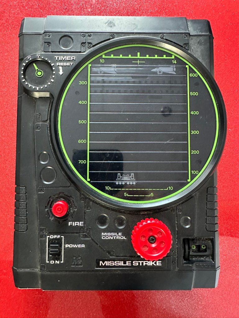
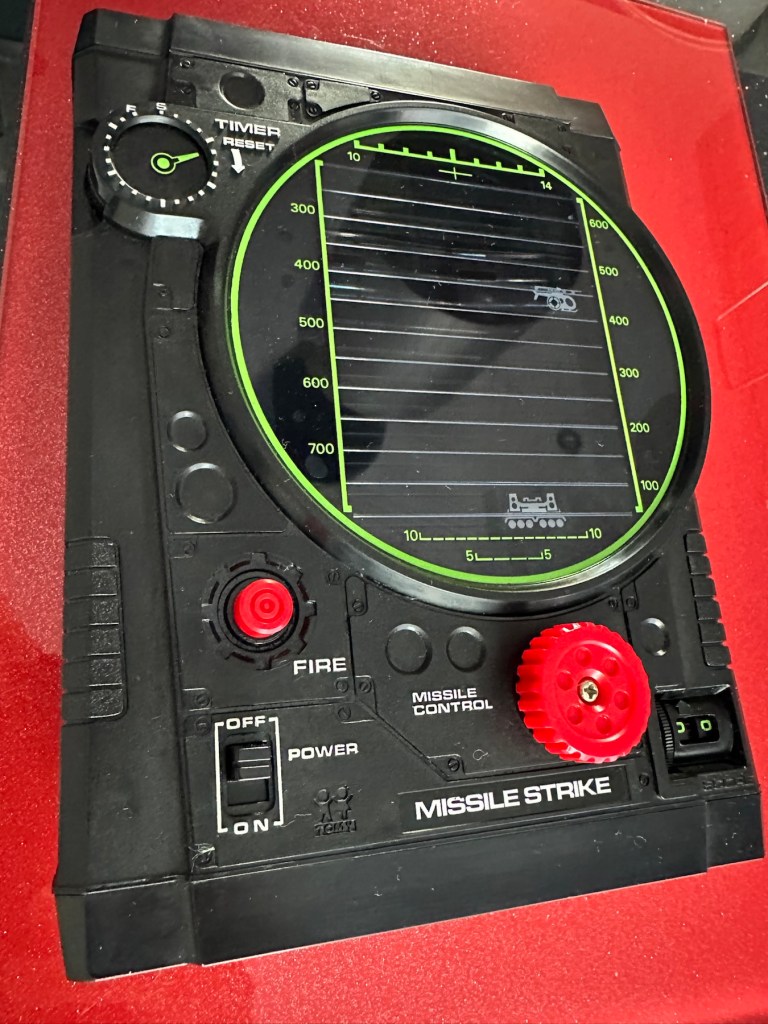
This is a nice example of a Tomy ‘Missile Strike’ electro/ mechanical handheld game. It was made circa 1979 and is battery operated. It appears clean for age and works, apart from the missile light not illuminating. Battery terminals very good. This is a nice genuine item that is shown as I found it. NOTE – NO BATTERIES ARE ENCLOSED. Nice example for any collector.
EBay
Missile strike
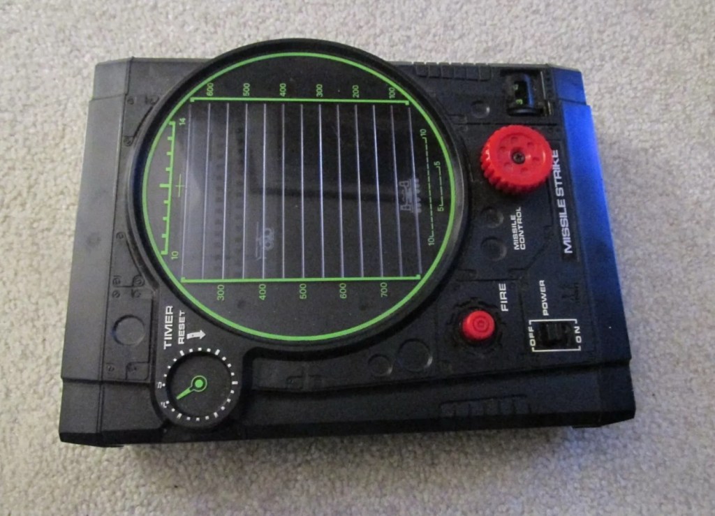
On first seeing the listing for this item, my thoughts are that it looks quite clean and tidy. The usual state of these units are quite tatty with scratched screens. This looks good, however pictures, especially from EBay can be greatly misleading so I’ll guess I will just have to be patient and wait.
This units only issue seems to be with the LED missile light, so hopefully it will be a quick fix. These units are currently selling between £52-£79GBP as per the picture below. I managed to secure my unit for a total including postage of £24GBP so I think I’ve done well in that aspect. I’m quite happy with this.
Current sale prices on EBay
A little history:
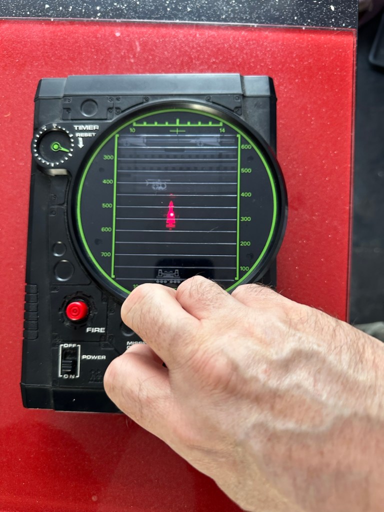
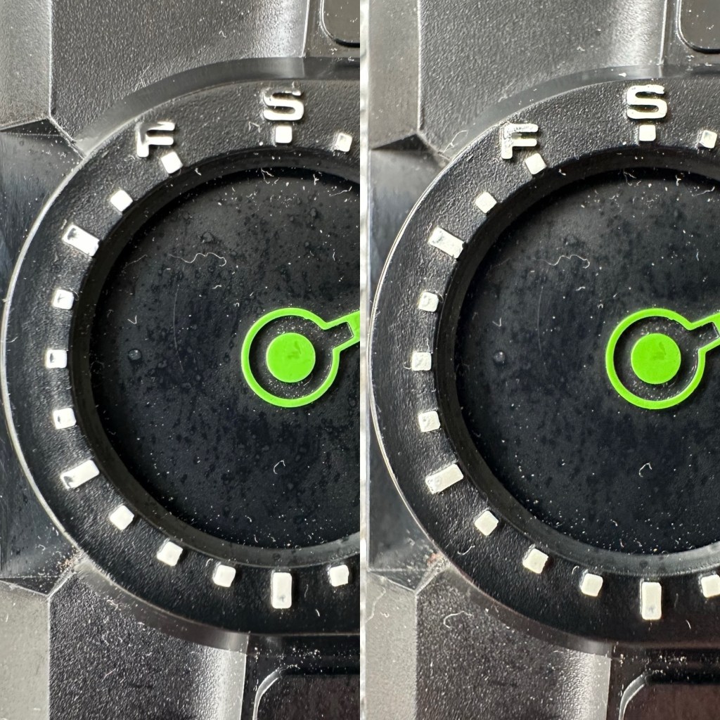
Tomy released Missile strike in 1979 in its international line of electro/mechanical handheld games. Known under different titles in other regions such as Terra-Hit (UK), Missile Strike (UK), and Space Attack (Japan). One of TOMY’s electro-mechanical handheld games, Missile strike is a Space Invaders-like shooter game, the units small motor winds strips of aircraft across the screen, which the player attempts to hit in order to earn points. There is a mechanical wind up timer that controls the action, and the purpose is to score as many hits on aircraft as possible with in the time it takes the winder to stop. The game includes one small, flashing LED light as the exploding missile.
So it’s another game that has reached its 46th year, and for the only issue to be its one light source, I think that’s acceptable. Let’s wait to see what arrives.
Assessment:
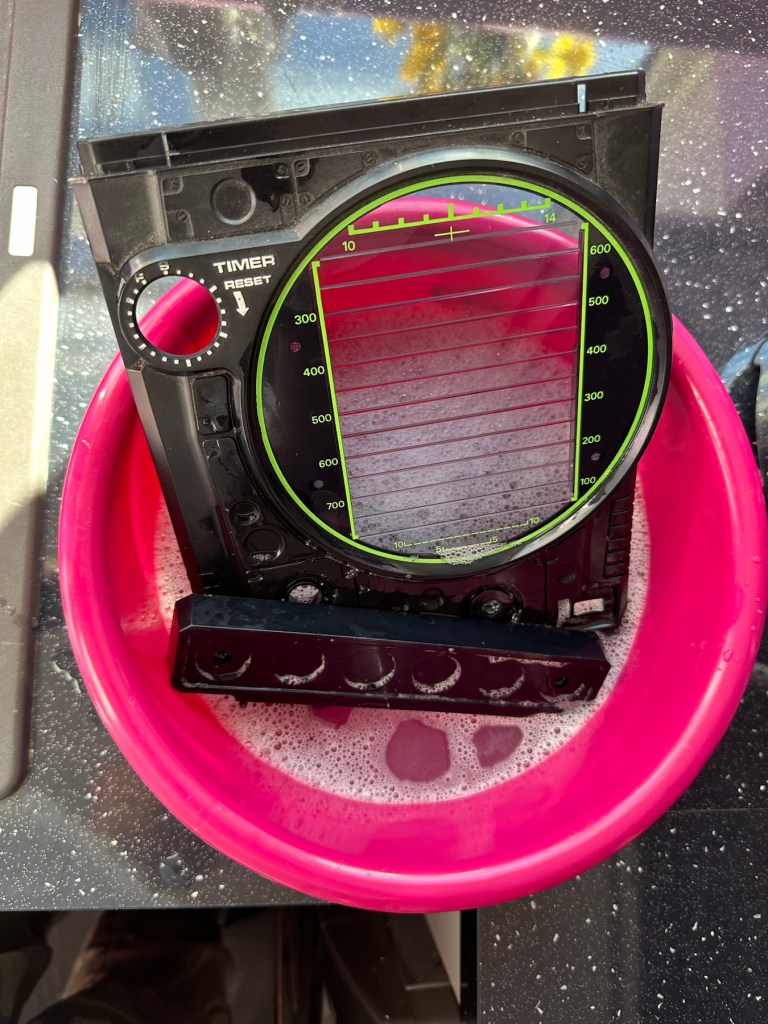
On arrival the first thing that hits you is that this is yet another filthy item. I seem to attract these kind of sales, so it will require a deep clean. Cosmetically the game is in good shape with no deep scarring and only minimal fine scratches on the screen lens commensurate with its 46 year old age.
Tidy cosmetically but filthy
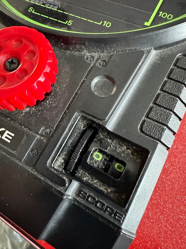
It was sold as the missile light not working, this is partially right as it is an intermittent fault, I suspect this is down to dirty contacts.
Filthy, and counter not workingMissile light is intermittent
This game has two bands of film that run across the top of the screen displaying aircraft, the top band is intermittent and needs attention. The score counter will also need attention as it is not turning smoothly, again I suspect this to be as a result of the build up of dirt.
Repair:
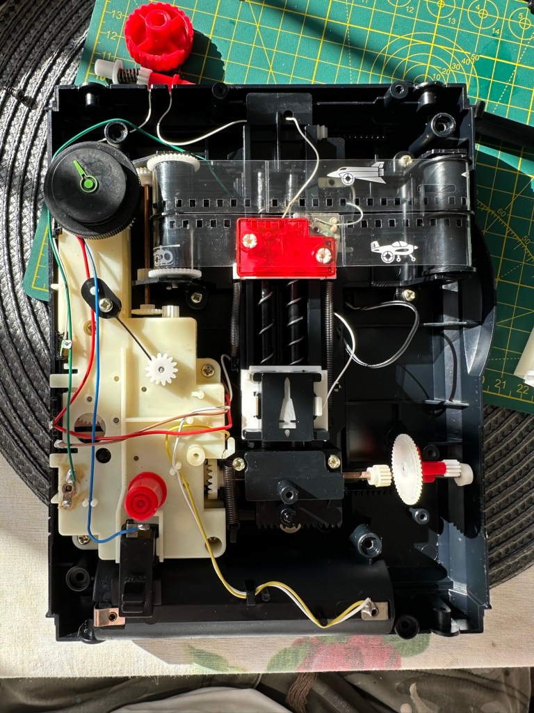
First thing to do is dismantle the unit and to get some cleaning done. The small video below shows the issue with the top band aircraft not moving.
Film transport fault
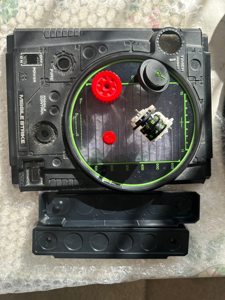
I’ve taken the counter out after removing the case and all exposed buttons and switches.
Dismantling
Off to the kitchen sink. let’s get these items washed.
To be cleaned Getting washedDrying down
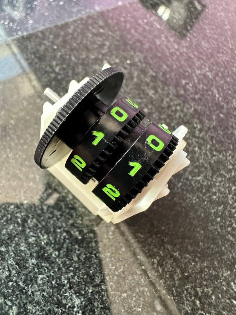
Whilst I’m waiting for the washed items to dry I clean the counter mechanism of old dirt and fluff.
I’ve slightly greased the counter with silicon grease and it’s behaving well and doing what it should. This will go back in place when we do the final reassembly.
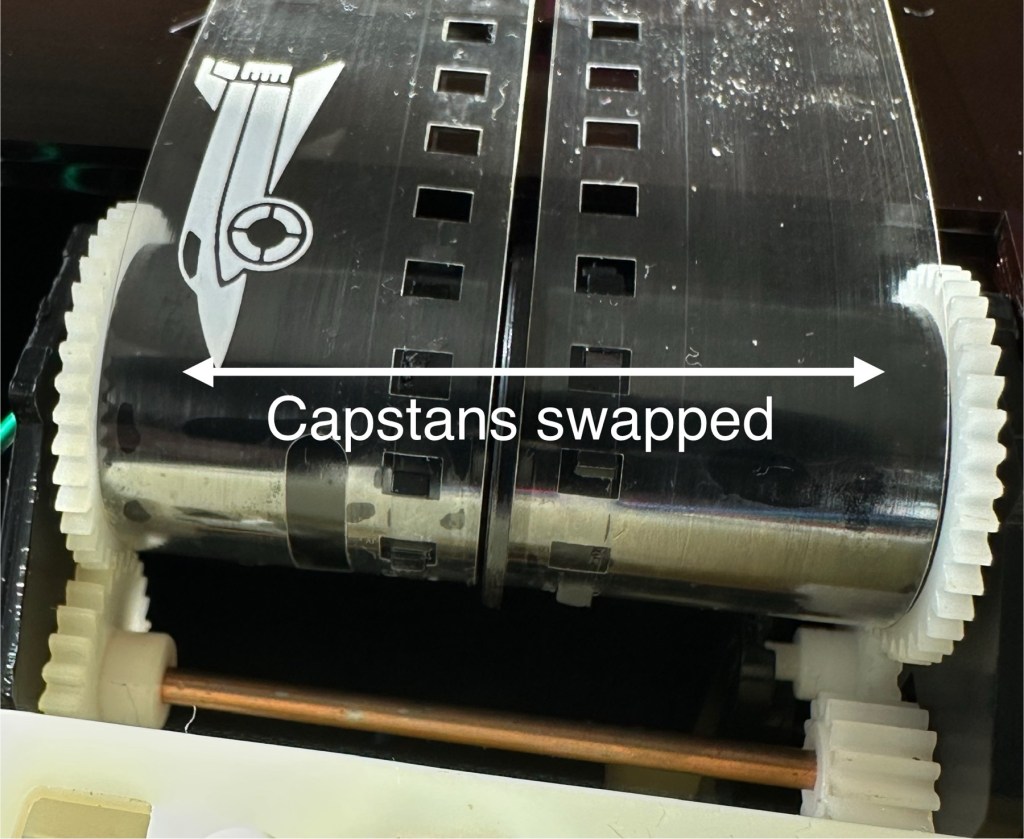
The issue with the film movement was a strange one. There was no way to tension the two capstans that the film roll over and there were no teeth missing off the capstans. One capstan pulls whilst the other pushes, all I’ve done is swap these around and the issue has disappeared. About as simple a fix as you can get.
Just swapped the capstans around
I’ve put a little before and after video here that shows the effect of swapping the capstans around.
How swapping capstans worked
The issue with the intermittent light was easy as expected. This is the only electrical piece on this game and it was down to contaminated battery contacts that just needed a bit of a clean with my grinding pen and a wipe over with IPA.
Final little touch was just to accentuate some of the old lettering by the timer. This was just with a white paint pen.
Before and after
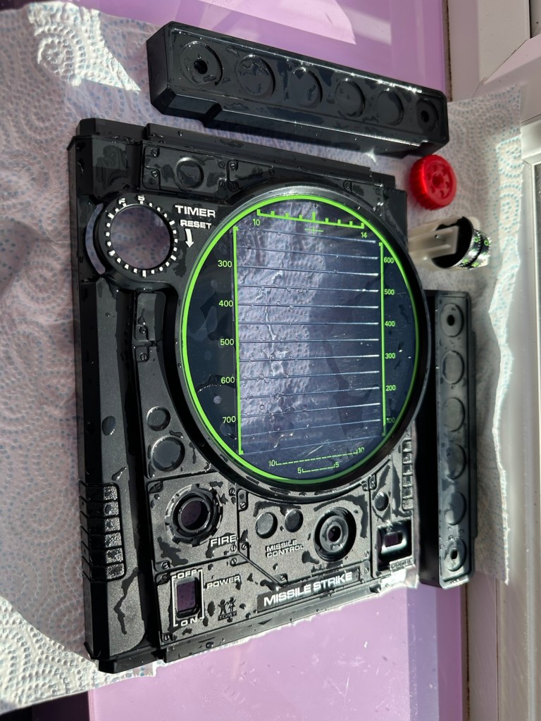
Now we can reassemble and test again.
Result:
The game has been reassembled and tested and is now working fine. All intermittent issues have gone and it has now been polished and now looks superb.
I’ve attached this small video that shows the game working as it should, with no film slipping and lights and counter now working.
Working perfectly
It’s really pleased me this repair, as it’s another one of those mainly mechanical games. Dirt featured big time, and age issues have been overcome and the game given a new lease of life. Another one for my personal collection, it will go on now for many more years to come.
The best outcome that was possible, we have another superb seventies product that has been saved from the scrap heap.
Fair overall condition some cosmetic damage as expected for a 56 year old item
Very rare well worth restoration if you know how
EBay
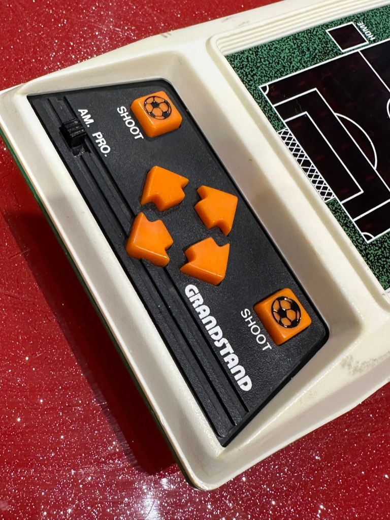
This guy sells retro games on EBay at exceptionally inflated, ridiculous prices. I suspect he doesn’t get involved with repair or renovation as he had this one advertised at over £30GBP but when I put in a cheeky bid for £12GBP he bit my hand off… I wasn’t expecting that! The usual mistakes in the listing such as stating it’s 56 years old when its actually 46, and stating it’s Very rare – it’s not, there were a few hundred thousand churned out and to be honest and they come up quite often on the sale sites. But I do agree it’s worth restoring and will pair up nicely with another retro football game from 1979 that i repaired a few months ago Bambino kick the goal football game. And what makes this unit even more appealing is that it is complete with both of its battery covers – now that is rare!
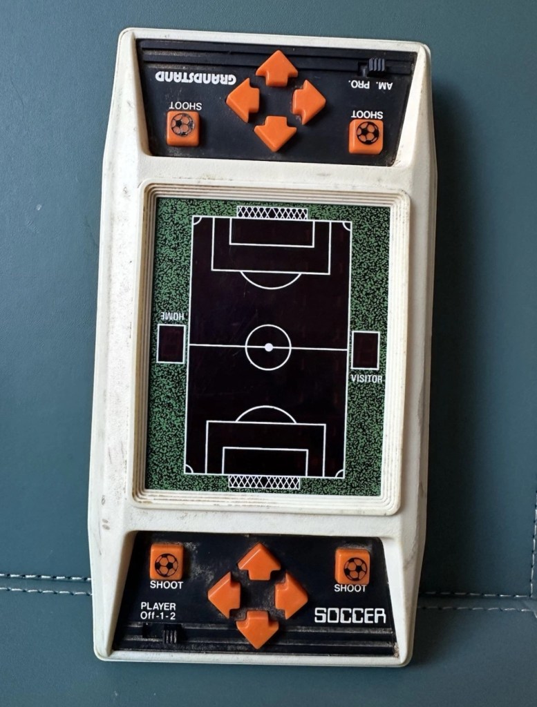
The game I have purchased Absolutely filthy
This game was made by Grandstand in 1979. Here’s the original advert that appeared on UK TV promoting the game back in the late 70’s.
European footballer of the year 1978/1979 Kevin Keegan – questionable late 70’s advert
This particular unit is listed as Not working, it looks filthy from what I can see, but having experience with these games in the past the biggest issue is age related problems such as old components, track decay and battery corrosion. No doubt the first thing I will do will be to dismantle it, give it a thorough inspection and then a good cleanup both inside and out. And then we can look at the issues around why it’s not operating.
Assessment:
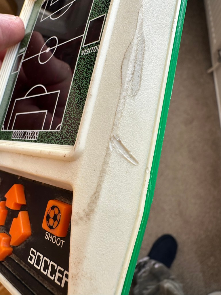
The unit has arrived today and it sure is filthy cosmetically. Like someone who has grown up throughout those 46 years it has its scars. It looks as if it has been placed against something hot, and shows a burn mark up one side.
How it looks on arrival
Caked in filth
Battle scars and burns
I have put batteries in and the good news is that there is life of sorts. By that I mean there is a distorted noise from the speaker and a flash of life on the screen and then it dies. Wiggle the start button and there are more flashes of life but that’s it. No other buttons seem to be working. I’m not tempting fate but this could be a case of the unit being just as filthy inside as well as out. But knowing my luck this will not be the case. Let’s have a look inside.
Repair:
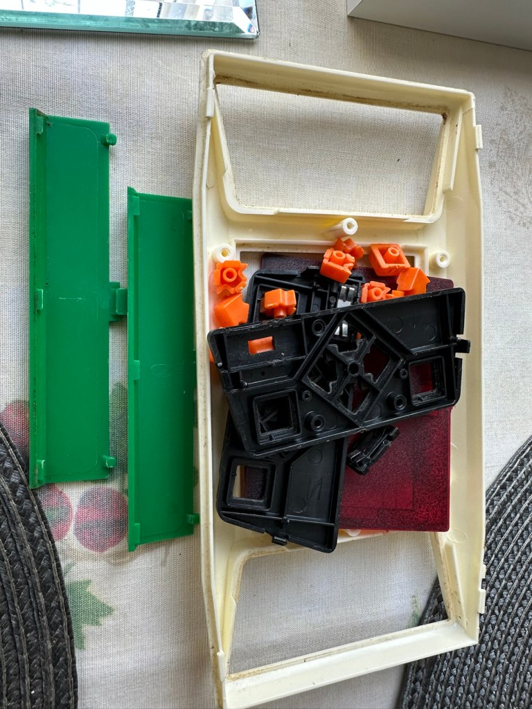
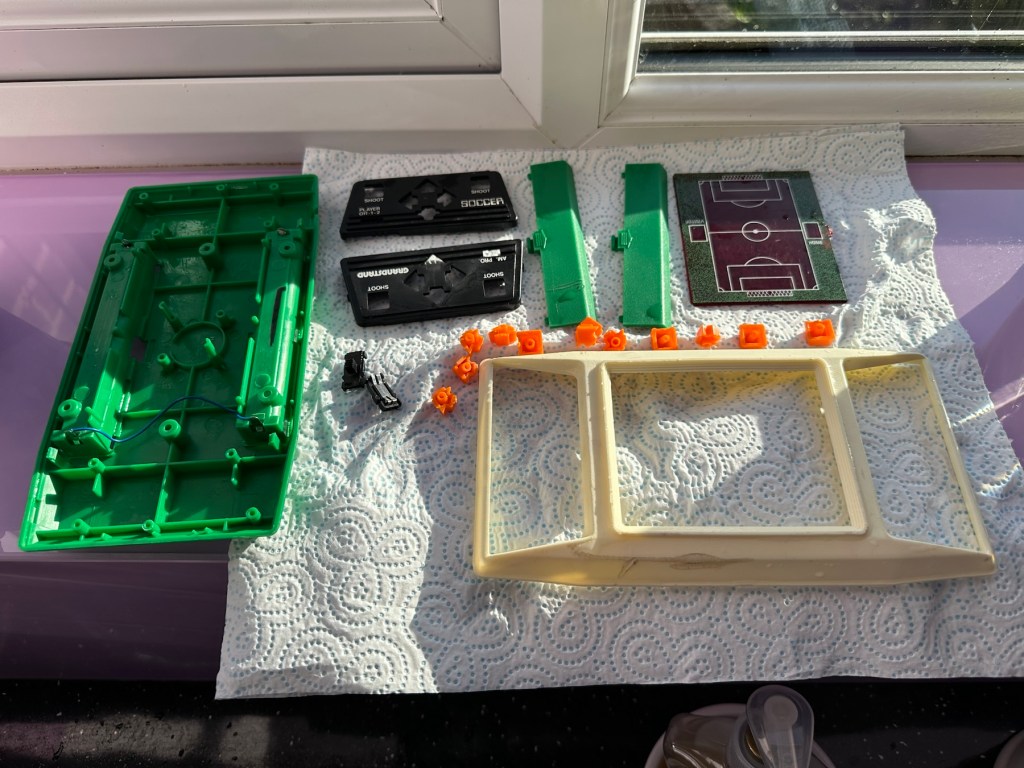
First of all we need to get the unit open, remove the circuit board and get the thing clean. So let’s do that.
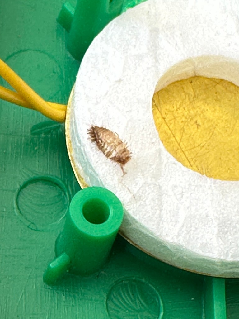
Utter filthCircuit board Push buttons to be cleaned, the rest is off to be washed. Even a dead bug inside 😧
As you can see in the pictures above, the inside hid a lot of accumulated dirt and grime, there were even dead bugs inside. Everything that could be washed was taken to the kitchen given a good soak, brush and rinse.
Off to the basinGood clean and scrubDrying on the window cill
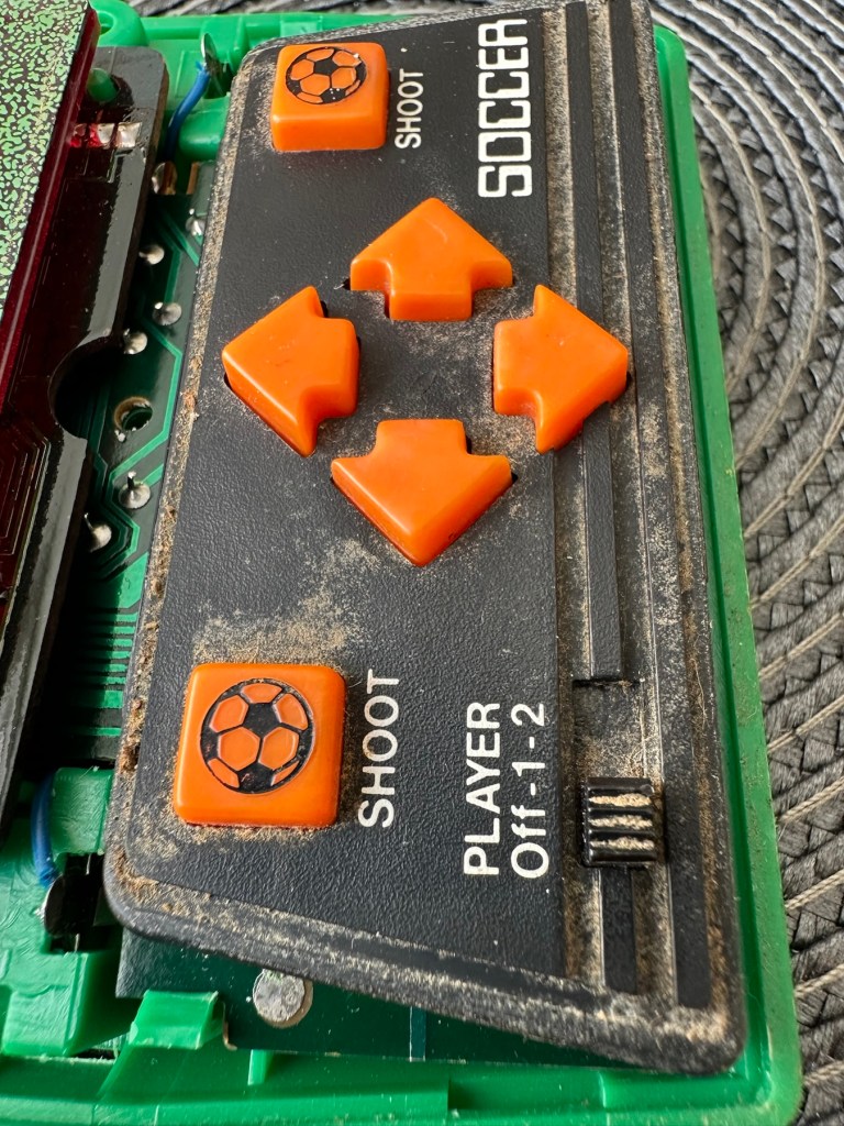
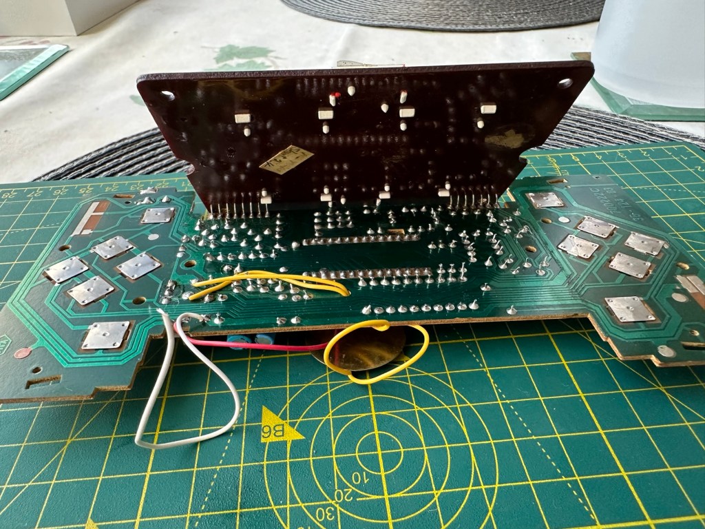
Whilst I’m waiting for everything to dry my attention turns to the board. A quick inspection reveals that all tracks are in a fair condition and we don’t need to rescue anything there. The buttons on either end have been taken apart and all cleaned with IPA, I’ve also used the same method to clean the switches and the board and after checking continuity all contacts are working as they should.
Board before cleaningChecking tracksNote found under upper portion of main board
Now everything is clean, I resolder the battery contacts, check the buttons and all appears well, I attach my bench power supply, give it 6v, turn on the switch and we have life. No intermittent issues and a very loud sounding speaker. I turn this off and look at getting it all reassembled.
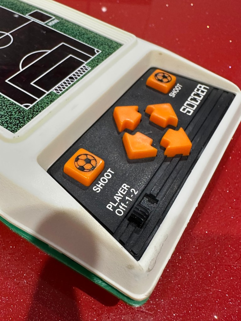
Unit now fully assembled, it is looking a whole lot healthier and apart from its burn scar is looking pretty good.
Where’s the dirt?TransformedLooking good
And when turned on it’s working just as well as it did back in 1979.
Result:
Sometimes these units just need some care and attention, and as I stated at the beginning all this really needed was a deep clean and service. Not a thing wrong with the electrical circuits apart from contamination on the contacts and switches.
All working. Job done
I’m now in possession of a lovely example of 70’s technology with slight battle scars. It’s had a tough life but now it has had a new lease of life and is good to go for many more years yet. It will take a place in my “Retirement home” collection of old discarded retro game units.
As always, it’s a win as we have prevented another unit being heaved into landfill.
Good condition and powers up but need to shake it to make ‘ball’ move.
Could be a spring tension has weakened or something
Box is very worn
EBay
Blip – 1977 LED Game
This purchase kind of excites me as it was a couple of years before games started to go truly digital. The year was 1977 some 48 yrs ago from the current time of writing. It was labelled as a digital game however that was a bit of a misnomer, it was more an electro mechanical game as the battery source in this unit had only one purpose, to power the LED light source. The main guts of the unit are mechanical being powered by a wind up motor that does the majority of the work. However the mechanics within this unit are superb and it’s worth a look under the cover just to revel in its construction.
These units were released at the time when pretty much the only video game available was the tennis game “Pong”. The TV game units produced at the time were selling for around £70GBP where as this unit was priced somewhere around the £8GBP mark. Hence, it was a cheap option for the children and didn’t need extra hardware such as a TV and a power supply. However, it wasn’t a match for the far superior “Pong”. It was in theory a totally different and far more frustrating game.
Want to give it a try? There is a really good true to life version available from the App Store to play on your phone. Believe me it will have you cussing as it’s not as easy as it looks. So realistic right down to the motor noise and light movement. It’s really addictive and annoying in equal measure.
The App for iPhone…it’s frustrating
This video below by Randi Rain shows a total refurbishment start to finish and is a great source of information regarding the breakdown and repair of this item.
Breakdown and restoration of a TOMY Blip
Some history:
Blip was designed by Hikoo Usami for the Tomy Kogyo Co., the patent being filed in 1976 and awarded on December 19, 1977.
Tomy marketed Blip in the U.S. starting in 1977. In Japan, Blip was marketed as World Tennis and differed from the U.S. game by having the words “World Tennis” emblazoned on the screen and replacing the 1, 2, and 3 on the screen with silhouettes of tennis players. The Blip name remained on the Japanese version. In France, the game was marketed by Meccatronic. The German version was called Blip-o-Matic, although the Blipname remained on the case.
It is the timer which provides the motor function to the game. Upon the timer dial being turned, a spring is wound which then, via several gears, drives the arm upon which the LED light (the ball) is mounted. The movement repeats after the ball hits each player’s side 36 times, so it is possible to memorise the sequence of buttons to press.
Wikipedia
I’m really looking forward to receiving this unit and can’t wait to get it up and running again. I’ve been after one of these for quite a while.
For those who may be interested and who have a photographic memory this is the sequence that the movement repeats in its 36 movement cycle:
The unit is in good cosmetic condition considering it is 48yrs old. The box is tatty but usable and as always smells a bit musty (To be honest as expected). The mechanical condition is not as described and is a total non starter. It seems the winder may have even been overwound, I hope this is not the case. The “Ball” light does come on when batteries are put in but only intermittently and when pressure is applied in the battery area. However the contacts do look clean with no sign of battery leakage or corrosion. And I know someone has been in this unit prior to me as one of the four body securing screws is missing. God knows what I will find awaiting me within. The seller has been a little, how can I say it, inconsistent with the truth in his description of this unit.
But that’s why I buy these things. Let’s get inside and find out what is needed to get it back into being a working game.
My unit. And the ball light came on for a few seconds to allow me to take this picture. Then promptly died again.
Repair:
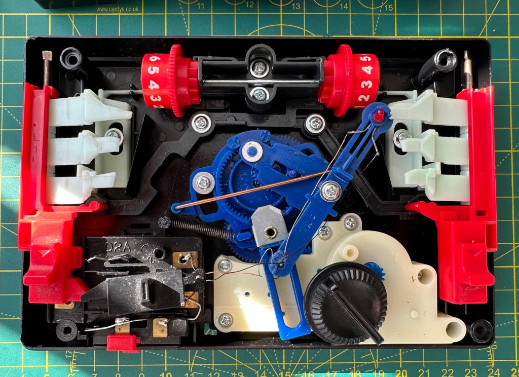
Open the case and this is what you are faced with.
Complex mechanical interior
If you remove the left and right control paddles you can get to see the mechanism running unhindered. However this one has an intermittent fault where the movement stops mid travel, there is something restricting its movement.
Something stopping movement
There is an inherent issue with these units where the gears have to be set up in exactly the right position or else it does not work. Similar to changing the timing belt on a car. This confirms to me that someone has been inside previously and messed with the gearing.
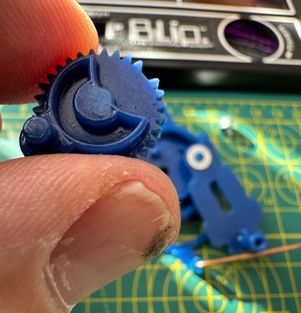
I also noticed a cog with a tooth missing, this was strange as to be honest it didn’t look as if there had ever been a tooth there in the first place!
Missing toothWas it ever missing?
Looking at its motion it transpires that this is another cog that just has to be in the perfect position and the “Missing tooth” corresponds with a flat post on the rear of the gear train. It’s missing for a purpose. This pleased me somewhat.
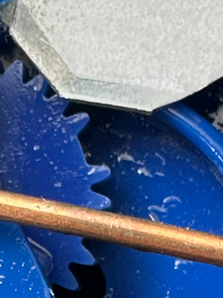
Calibration holes on the cogs correspond with holes in the shell base.
I put the cogs back in place paying special attention to their positioning and tried the unit once again. Here is the result.
Now a nice smooth movement
Next I’ve taken the light switch to pieces, I’ve cleaned all the contacts with IPA, reshaped the contact and put back together.
Switch dismantled, cleaned and reassembled
I’m pleased to say this did the job, the light works fine and there is no longer an intermittent fault. It’s all that was required.
I have reassembled the unit, given it a good clean and it looks pretty smart if I say so myself. It was already well oiled so there was no need to add more at this point. It is now fully working and will last a good few more years yet.
Now Working
Result:
A successful repair of a 48yr old toy game. I’m really pleased with my purchase and it’s another cracking example to add to my ever growing collection.
All clean and looking smart
Repairs on these games need approaching from a different point of view. The electronic content is minimal and mechanical workings are the order of the day. Look how it has all reversed in today’s gaming world, that’s advancement for you.
Really pleasing positive result here. Another one saved from landfill.
Thanks for passing by and reading this post. It’s always very much appreciated.
I follow a number of channels on YouTube. It’s the only social media site apart from this one that I do get involved in. I have absolutely no intention of ever making a living on these platforms as to be honest I couldn’t really be arsed to.
Hugh tells you how it is
However a lot of individuals nowadays want to do just that and make their livings on line.
Now Hugh has a very interesting site for someone like me that likes anything from the retro era. He’s been without a smartphone for over a year and his progress without one has been really interesting to follow.
Hugh does earn from his online presence but to be honest it isn’t a living. He goes through the figures in this video that show all the hoops you have to jump through to earn a living from having an online presence.
To build a usable, basic issue, medium format camera (Bronica SQ/SQ-A) from damaged items and spare parts, for as little outlay as possible and shoot one black and white, and one colour roll of film as proof of its successful completion.
Getting started:
Building a camera from damaged parts is no easy task when the name happens to be a high end brand and any parts that are available, are being snapped up by others to service their own stock or to break up for sellable parts. I’m going to keep a running total to try and build this as cheaply as possible, and to keep track of this total I’m going to use my trusty Psion Organiser II LZ from 1989 to keep a tally.
First purchase:
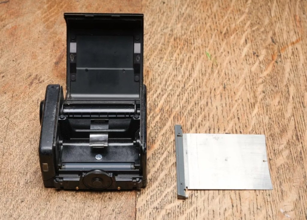
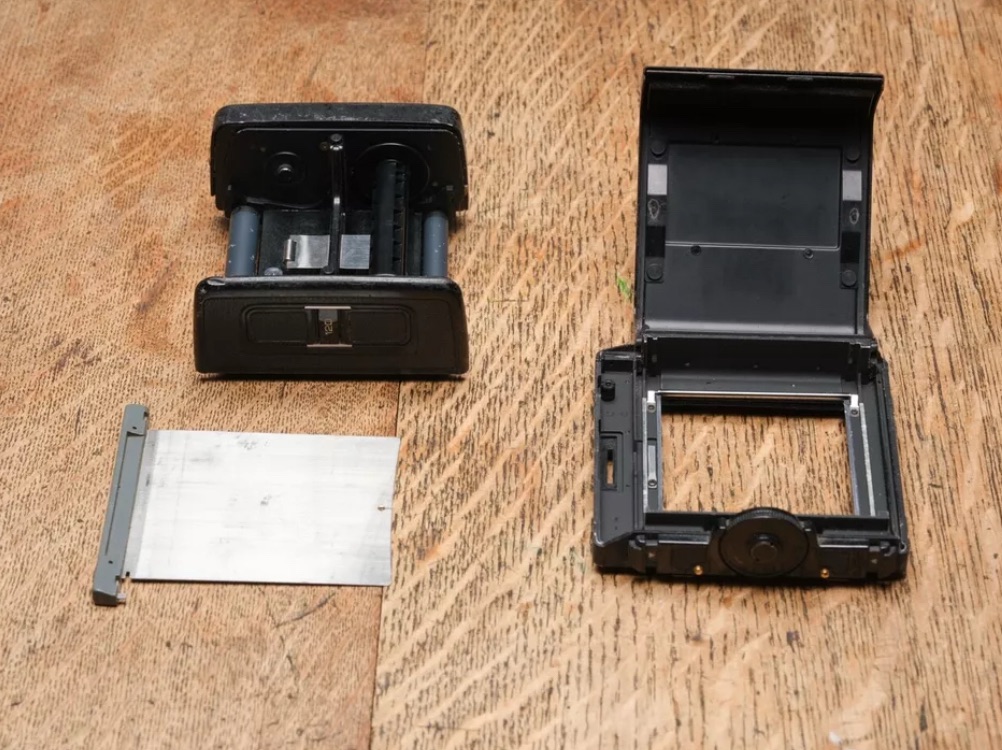
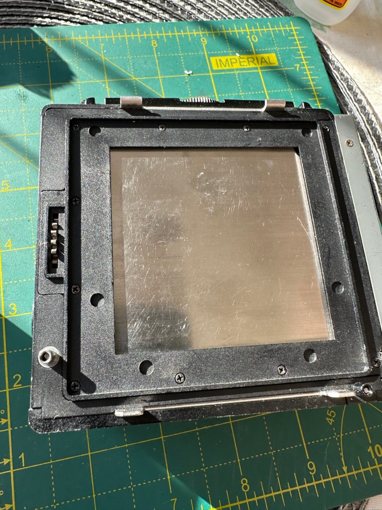
The first purchase has been made and it is for a 6×6 120 roll film back unit with dark slide. I think I’ve paid quite a good price for this item. This is the back piece that fits on the rear of the camera. Here is what the listing stated:
ZENZA BRONICA SQ 6X6 120 ROLL FILM BACK WITH DARK SLIDE Signs of wear, untested. Uk Buyers Only Please
EBay
First purchase, the film back.
And the total paid including all postage is £20:94GBP. Let’s now start the running total in the Psion II LZ.
Running total
All I can really check at the moment is cosmetic condition and this looks a little beat up, however I don’t really care how it looks externally, as long as it’s light tight, that is all that matters and I won’t even be able to check that until later on in the build. Cosmetically I will attend to it, if I feel so inclined at the end of the project, for now it’s ability to be light tight will be my major concern.
Assessment:
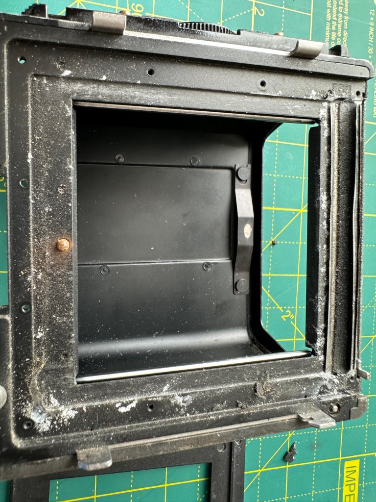
The unit has arrived and yes it has seen use, but not in a few years I suspect. The old smell hit me the second the package was opened, it’s kind of a reminiscent pong from the past, however I’ve got to see beyond this.
The light slide seems fine, however the surrounding frame has been bashed and a small bit of frame has gone missing. There is also a screw missing and I suspect the area that is missing the screw may well have been glued down. there are some slight rust spots on the exterior framework, however everything inside appears to be fine apart from some light seals that will probably need replacing. The rollers inside are grubby so a good overall clean is in order.
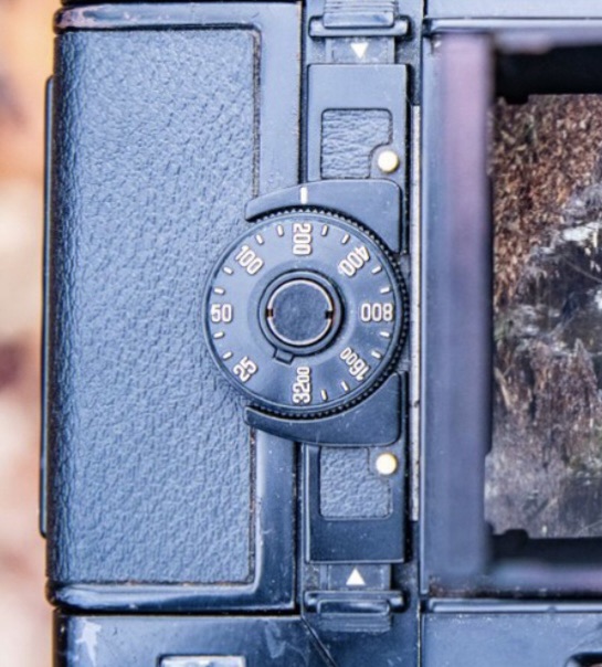
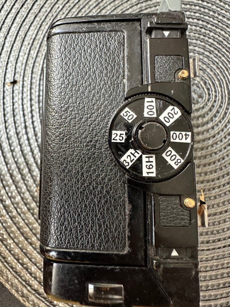
Annoyingly the ASA markings on the dial atop of the roll holder are missing. I will make something basic up to remedy this issue. Again it’s an exterior issue and I’m not too fussed at the moment.
Yes there is some work required, but there is no rush. And thankfully I don’t see anything that really scares me about it. I won’t really know how it stands mechanically until I find a suitable body to attach it to. I have that to look forward to in a future post.
Repairs:
The ASA dial. Simple solution here, until one becomes available sometime in the distant future, is to use some very small dymo labels I have printed. I will cut these down to size and put them in place where they should be on the dial. Quick and temporary solution a’la Frankenstein. No need to over manufacture things, this will do fine.
Size 9 dymo labelsHow it should lookHow mine currently looksAfter I’ve added some ASA numbers- temporarily
The old asa wheel has been cleaned to remove the original glue, and temporary stickers have now been applied. This completes this fix for the ASA dial, for now.
Two items to make one good unit
Edit: I’ve managed to obtain a damaged roll back for a grand total of £5:76GBP, absolute bargain and it also has a working ASA dial. So I’m hoping I’ll be able to use this donor to help in the repair of this item. I’ve used a combination of parts from this and the earlier roll back and I’m happy I have a good working unit. We now have a proper ASA dial off of the spare unit transplanted onto the old unit.
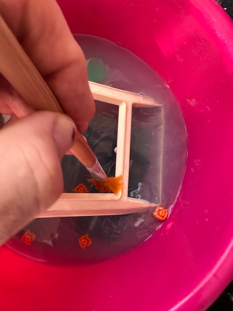
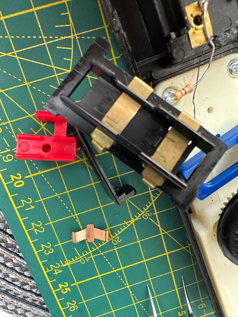
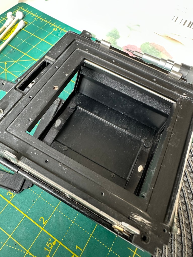
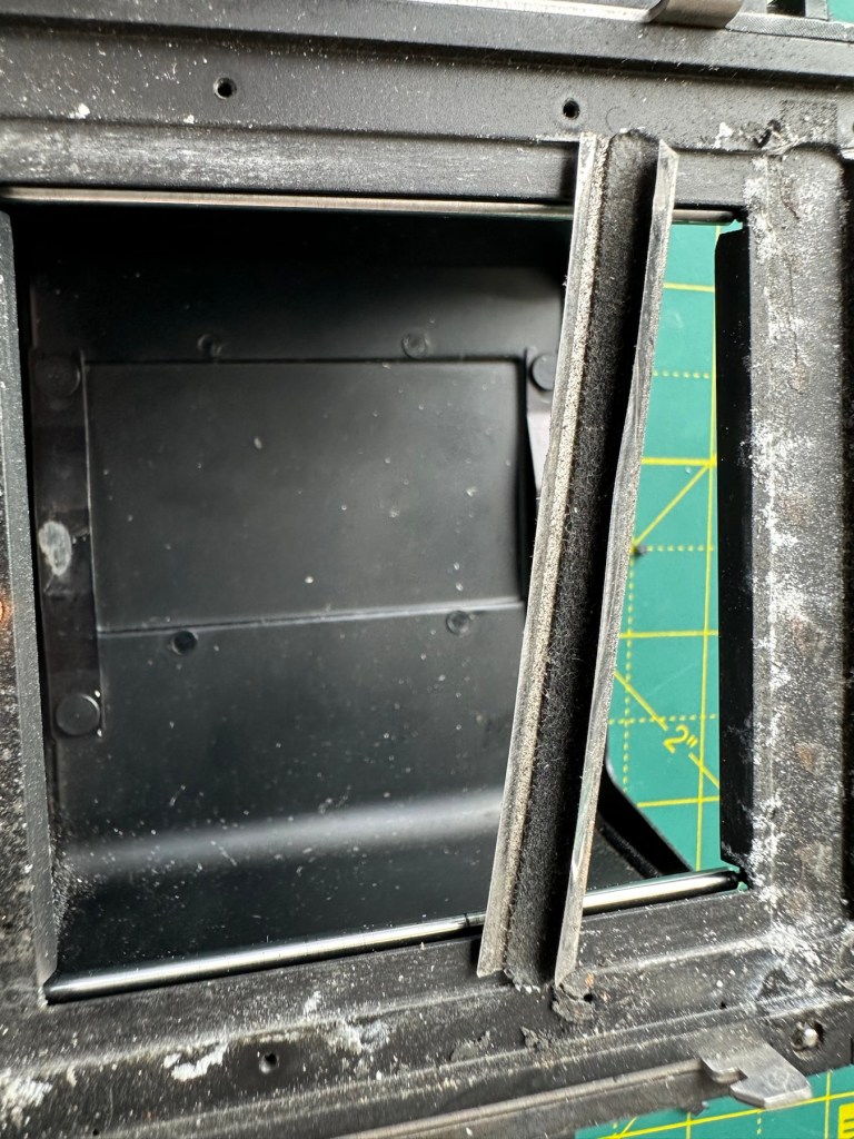
Front frame:
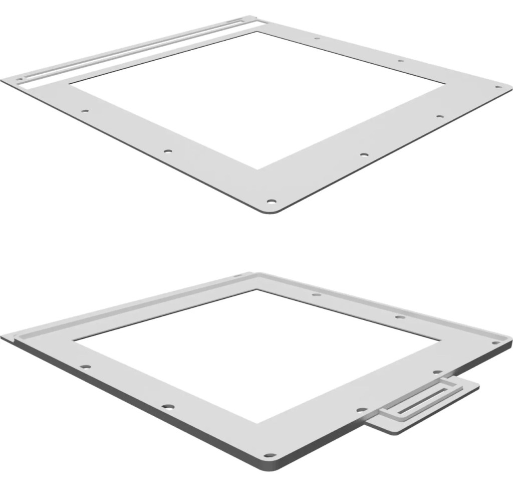
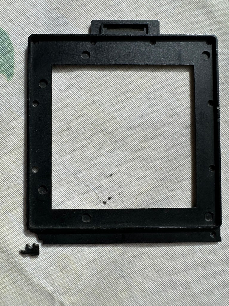
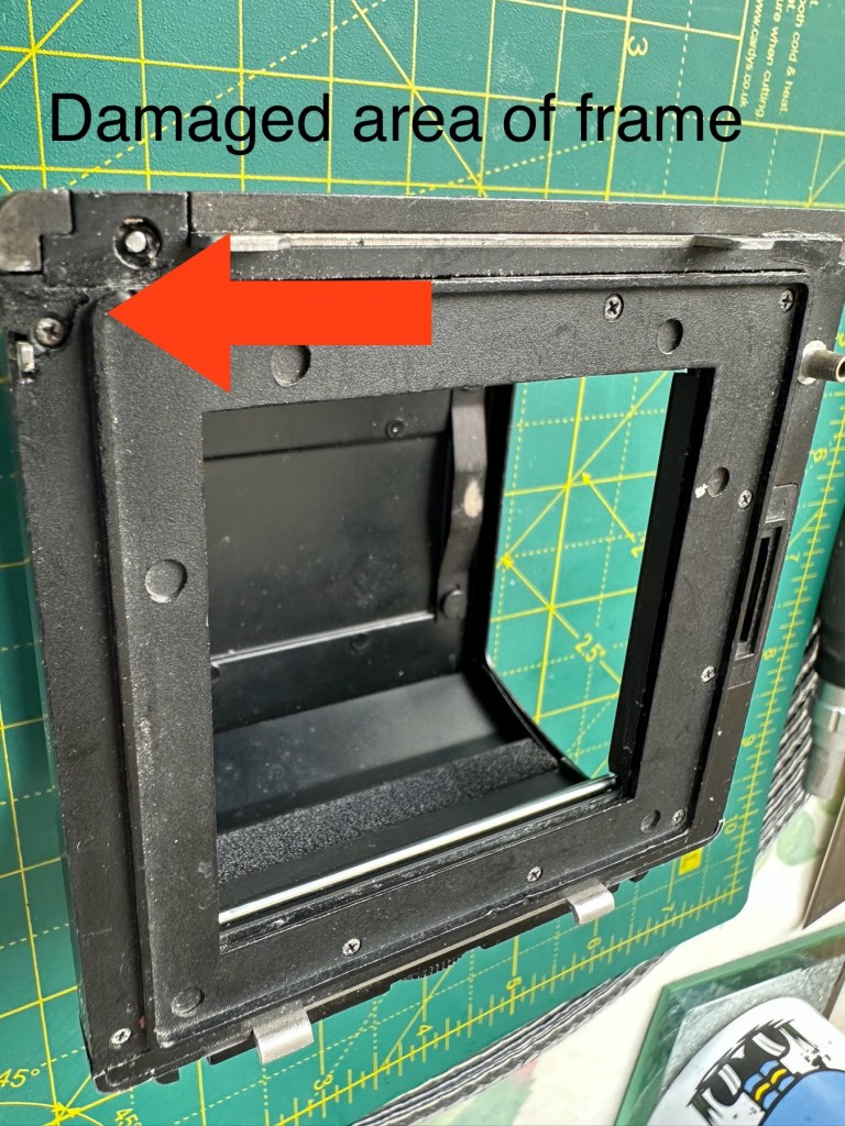
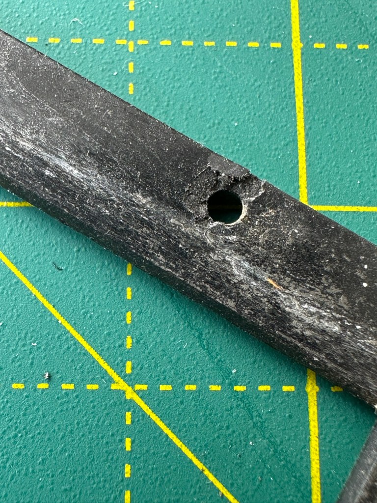
I’m taking this off to give the whole area underneath it a good clean. There are some film guides under this frame that are contaminated and that could cause a scratch on the film, I’m going to clean this whole area under the frame and will then reassemble. The cartridge slide is in a good condition and has just required a polish. Apparently this front frame is prone to breaking and the screw holes splitting, as it gets quite brittle. This has happened to this unit, and I’ve found a guy that 3D print’s replacement front frames and I have ordered one of these to ensure that the whole frame is secure and light tight, as currently one corner can be lifted and this could cause a fogging issue. At a cost include postage of £12:75GBP it’s a small price to pay seeing the only way to get one nowadays is by purchasing a donor unit at cost far exceeding what I have paid here.
The new frame, will be blackThe old frame with broken corner and damaged screw holesDamaged area of frame in situ on the roll back
There are a couple of screws missing of which I have plenty of spares so these will be simply replaced. I’m happy now that this portion of the camera is in a good condition and will soon be ready to be put to use.
Before AfterDirty seals Damaged frameworkRemoval of the frame presented years of debris and filth that needed cleaning as well as a requirement for some replacement parts
There was a lot of contamination under the plate when it was removed, I was quite amazed just how bad it was. This has since been cleaned prior to the new frame and seals being put back into place. When everything is re assembled there will be another clean, I will also be using compressed air to finally clear any remaining debris from the roll back. Edit: the 3D printed frame has arrived and to be totally truthful it’s not much good. The part where the slide goes in is not usable and I’m not confident this will be as light tight as first thought.
Good front frame from the donor spare unit
However the spare unit I purchased has a good front frame that just needed a tiny bit of adjustment to work, I’m now confident the roll unit will work as it should.
Light seals:
To be honest there are only two immediate areas of concern that I can see. All other light seals seem to be sufficient. I already have plenty of light seals material from where I fix other cameras so this should be simple enough to replace.
New and old light seals replaced
There were only two pieces that needed replacing, these were both on the roll film back. All other light seals were fine.
Rust spots:
These are purely external and there are no issues inside the cartridge. However I may just give them a very fine rub down and a quick spray with a black gloss to just make them look better. Then again I may not, and then I’ll attend to the cosmetics once I have completed the project. Edit: I’ve decided to leave this for the moment and will attend to this sometime in the future as it is not affecting anything at this stage.
Film cartridge:
Again this has just been cleaned and some contamination has been removed from all rollers and guides within. I have adjusted the back plate pressure pad for the film and also given this a good clean to remove any contaminants. I’m happy the internal cartridge is in a good condition and only requires a light clean. This cartridge is superior to the one I have obtained as a spare so this will be the one i work with. I have replaced all the exterior screws to replace the original ones as they were all a little crusty and contaminated.
New screws. I will touch the heads up with black dye
The whole roll section has been cleaned with tack cloths and compressed air to ensure all contaminants have been removed.
I’m going to store the whole roll film back, in a sealed plastic bag with some Silica gel packs to try and remedy the mustiness that I mentioned at the beginning of this post, though I must admit after all the cleaning and replacement of parts, the issue has reduced immensely. Some exposure to sunlight on a window seal usually helps immensely. That’s where it’s sitting for the moment. It’ll go in the bag with some silica gel, during the more inclement weather.
Outcome:
This part has been the most demanding part of this project so far. I’ve looked into the possibility of using 3D made parts, but I must admit defeat here. The items are about 80% ok, there are holes missing that should be there and as it’s a two piece fix you are then introducing glues, and potentially increasing the chances of light accessing the one area you want dark. Maybe in time they may perfect it. I was exceptionally lucky to obtain a spares unit for literally one pence. Yes one whole pence. It cost £5:75 to post making a total of £5:76GBP, but in many aspects some of its parts were far superior to what I already had. I am happy that this part of the build is now complete.
All good to go. Please keep an eye on the other blog posts that are coming regarding this project.
Can’t get to turn on unfortunately. No battery cover. Any questions please ask
EBay
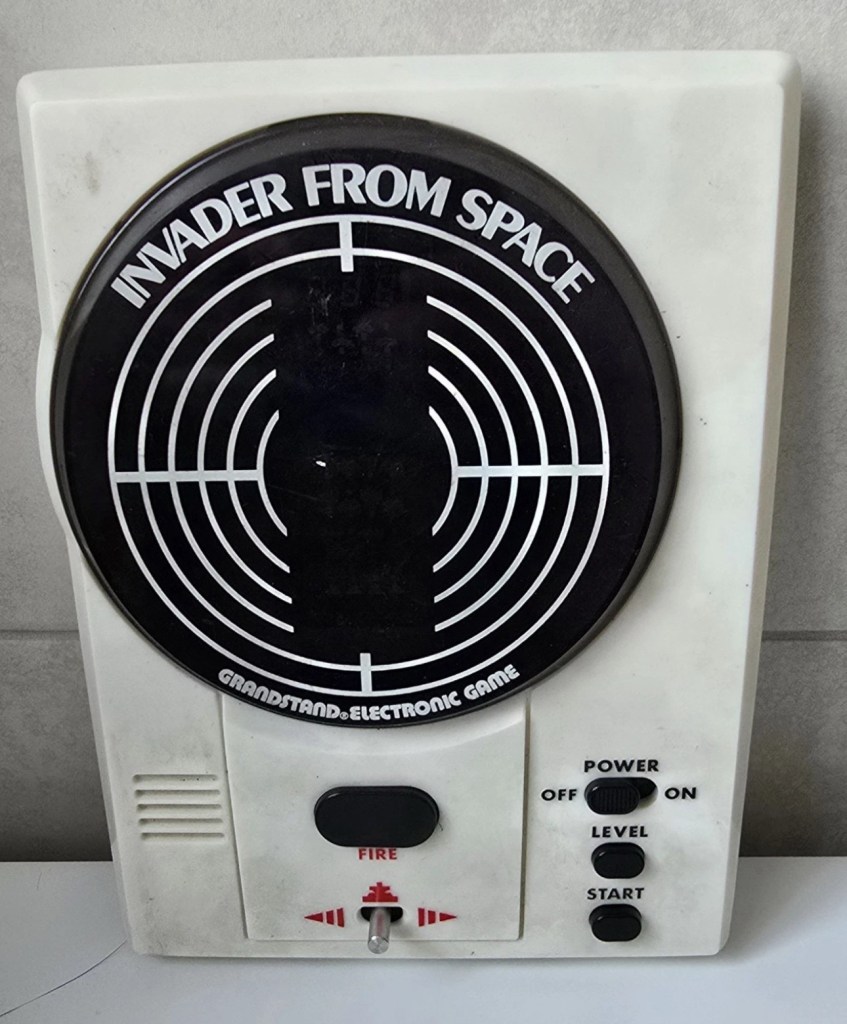
Dirty unit No battery cover
I know, there is no battery cover, however I have already sourced a seller of one if needed. This item looks quite dirty so a good soak might be the order of the day to get started. I’ll wait for its arrival before I jump to order any other bits for it.
Now as I’ve said in the past these units fall into that crazy price category on the selling platforms as the “New Antiques” of today. For an item that was low cost, somewhere between £25-40GBP when it came on the market, they can certainly command a wide range of crazy prices, here is an example of price ranges from today:
The massive range in prices for these units
This one I purchased today only came up for sale about 3 hrs ago and I thought it would have been snapped up by now, it hadn’t so I didn’t hang around any longer and purchased it for a total of £16:38GBP including its delivery. I’m not going to get too smug yet, as for all I know I may have just purchased an empty shell. Let’s wait until it arrives.
Here’s a little history of this unit:
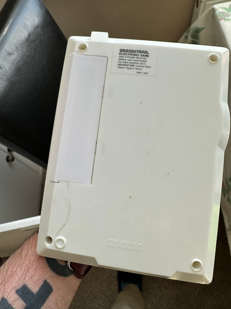
Grandstand “Invader from Space” is a tabletop LED game dating back 45 years to 1980. Four ‘AA’ batteries power the unit or, alternatively, the Grandstand 5.5V@300mA power adapter (or an equivalent power pack) sold separately. The game, licensed to Grandstand, is a copy of Epoch’s “Invader from Space”
The company initially behind the “Grandstand” label was Adam Imports Ltd., (from 1980 Adam Leisure Group Ltd. and by 1983 Adam Leisure Group PLC) founded in 1973 by Chris Rycroft and Les Kenyon of Harrogate, UK. The company initially started as a mail order company and was the single largest supplier of calculators in the UK by 1974. By August 1978, George Bassett had acquired a 75% holding in the capital of Adam Imports for £750,000 cash, plus 60p in the pound of profits before tax in excess of £500,000 for year to December 31, 1978. Adam Imports was re-acquired from George Bassett by Chris Rycroft in 1980. It chiefly imported electronic products from other manufacturers such as VTech, Epoch, Tomy & Entex, selling them in the UK re-branded under the Grandstand name.
Wikipedia and others
So that’s the history
There is a good link to a similar repair on YouTube from a guy I follow named Stez Stix Fix, it’s very much worth a look and he has a great if not sometimes crazy way of diagnosing and repairing items. A cool guy though.
The Grandstand invaders from space game
Anyway back to my own purchase.
Assessment:
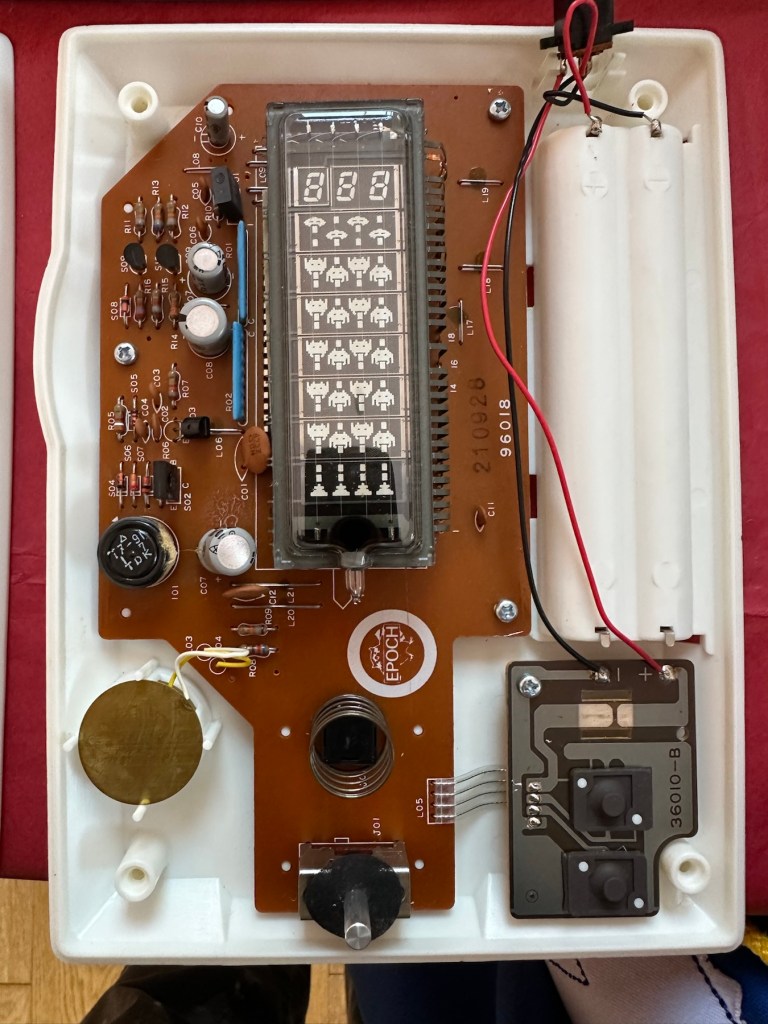
I must admit the unit doesn’t look as dirty as in the original pictures. The battery cover is missing and there is a crack in the side and a deep scar at the bottom, this won’t be too much of an issue if I can weld it all back together. I will still give it a good soak to clean it all up though. I’ve put four batteries in place, and the unit is definitely dead. There are no loose wires, voltages are getting around the board according to the multimeter and nothing is getting hot. There appears to be no short circuits, and then I notice this, capacitor CO7, slight bulge on top and what looks like leakage from the bottom. We have a candidate as to why this unit is not working.
CO7 looking unhealthy to me, you can see the component to the left that looks like it’s covered in a fur ball. The result of the old capacitor “coughing”
I’ll whip this out and see what we have but I suspect this old capacitor has failed and is causing an issue, heres hoping I have a suitable replacement.
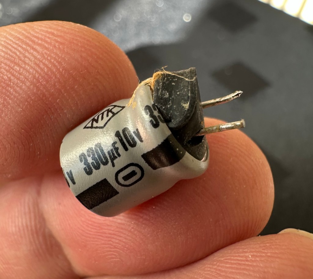
Repair:
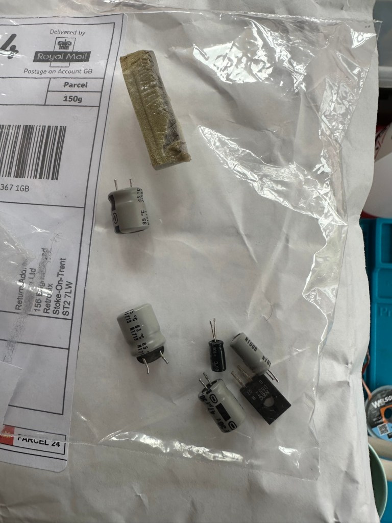
This little beast is a 330uf 10v electrolytic capacitor. I have none available so have had to purchase a pack of ten. These should be here in the next few days. There are three other old electrolytic capacitors that I will also change whilst I’m in there, as these are all likely to fail at some point soon. These components are now all around 45 years old, it’s a wise move to change them out.
One very dead capacitor removed.
I’ve ordered a 3D printed battery cover to replace the one that is missing. This should be here in a couple of weeks.
Whilst waiting I have cleaned the inside and outside of the casing as best I can. I still have a piece of broken surround to repair, however this is just a simple glue and a little bit of support job.
Case inside and out cleaned
Broken surround repaired
The surround that was broken has been repaired and secured with some nylon soaked in a superglue compound inside the casing. It’s rock solid. Outside the break is hardly noticeable. The break is secure and much stronger now.
New capacitor here
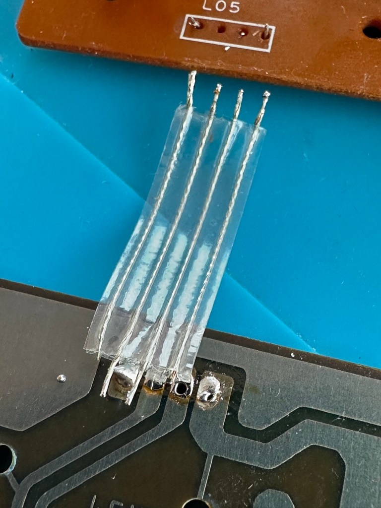
I’ve replaced all the offending capacitors and the unit remains dead. I’ve reflowed most of the board as there were some dry solder joints. I’ve also rewired the bridge from the control panel to the main board as one of the wires here had broken.
Bridge required resoldering
After using the multimeter to check some traces and components it’s now pointing to this component (a power transistor D882) being the cause of this catastrophic breakdown as its readings are all over the place. I suspect this item has overheated, the capacitor has blown and then it’s just died itself. I’m probably wrong, but I know what I mean. Probably just a catastrophic chain of events that all contributed to the units demise.
D882 transistor – power regulator
And as usual I have none available so will have to send for some new ones. The new components have arrived and the new power transistor has taken its place on the board. Now reassembled I place some new batteries in and the unit comes to life. It was the power transistor at fault, I should have really checked here first after seeing that damaged capacitor at the beginning.
All old components removed and replaced in this unit
Not to worry though as it’s had a good overhaul and has been totally recapped as a precaution. I’ve used some conformal coating on a few tracks that had some copper exposed after a good clean, to ensure they don’t deteriorate any further.
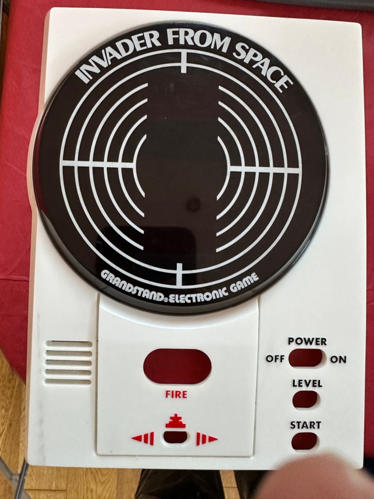
It has life
The unit is looking really good and these items were traditionally very loud and this certainly is. It’s working well just as it should do and I’m exceptionally happy with this repair. I’m still awaiting the battery cover that I have had 3D printed and this should be here in the next week to complete the fix.
No scoreHere we go3D printed cover arrived. Minor adjustments needed but in all a good purchase
So with that I will bring this build to a conclusion. It has been a fun project, I’ve learned a number of things about this circuit board and gained valuable knowledge.
But best of all we have rescued another item and saved it from landfill.
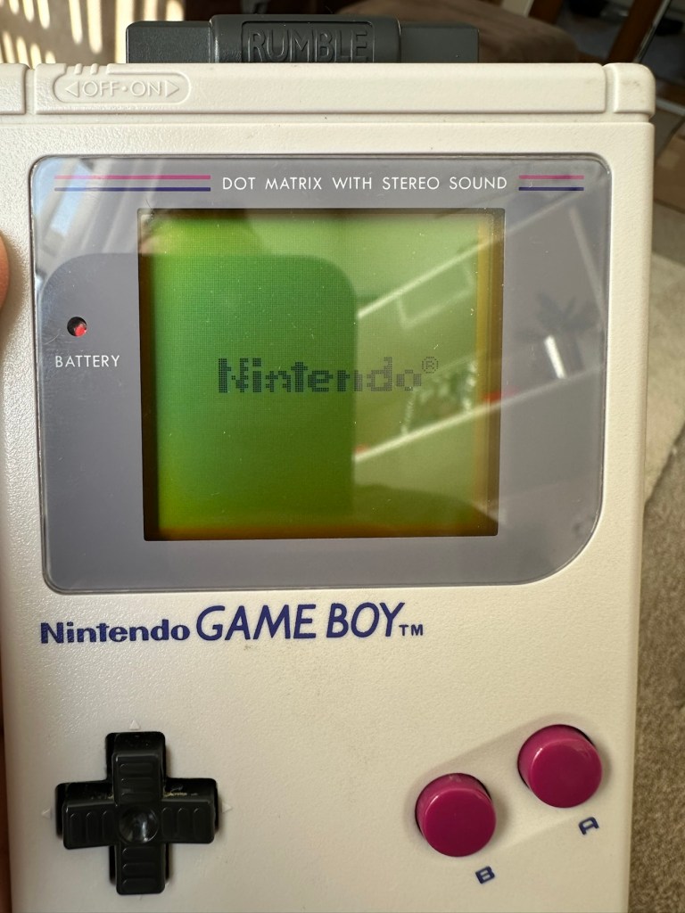
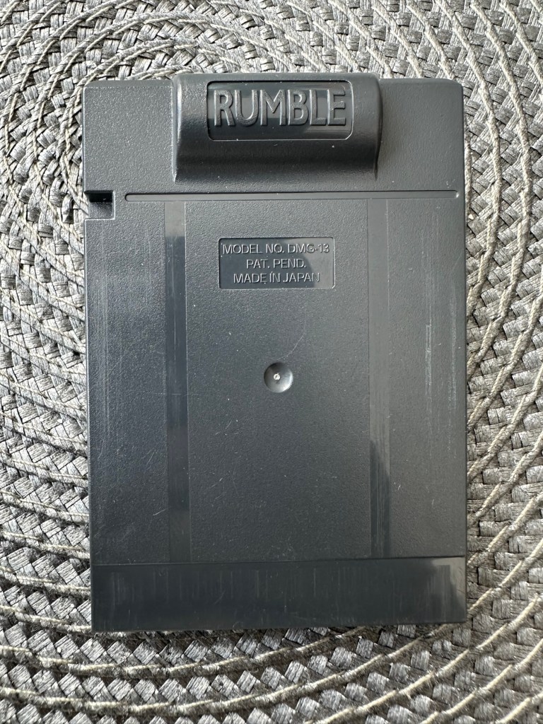
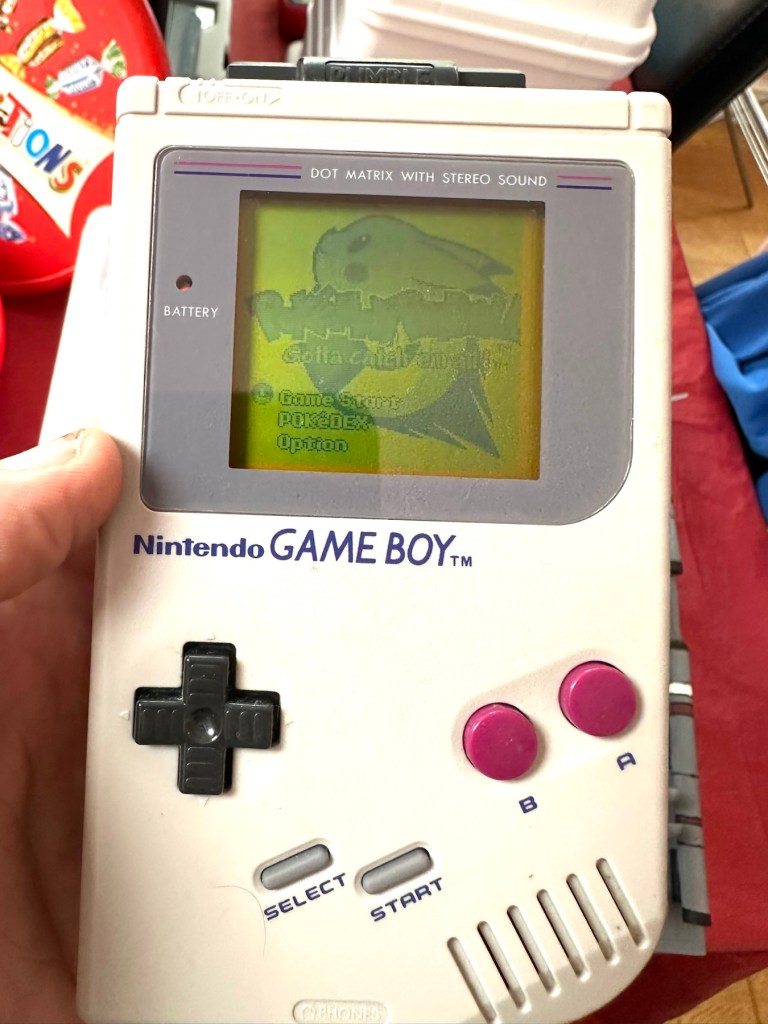
You will receive what you see in the photos, please look at the photos as this is part of my description to show you what you would be receiving. Please note the game comes up with the main Game Boy & Nintendo screen & then won’t go any further, as you can see👀in the photo.
Any questions please feel free to ask.
EBay
No getting past this pointOriginal Nintendo pinball game – Non operational
Hopefully this will be a simple repair, but who knows it might just be a little more technical.
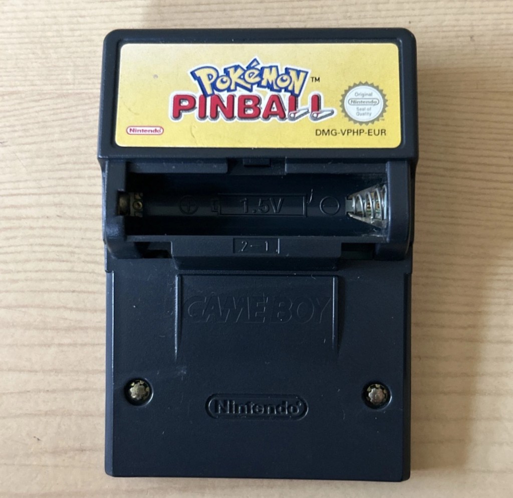
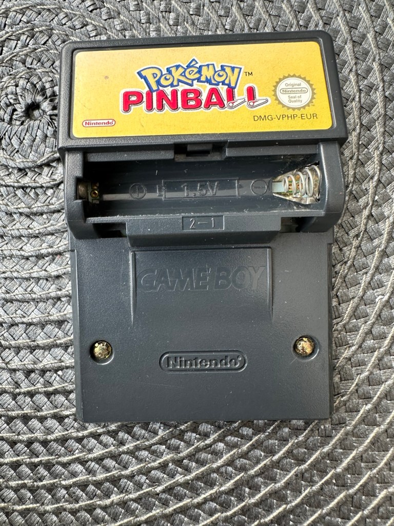
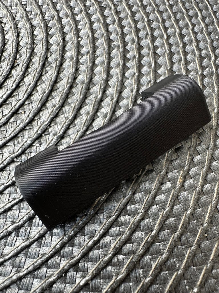
This game is built for the game boy colour console and is an original Nintendo product, it is the Pokémon pinball game. I’ve purchased something I never normally buy and usually detest buying, an item with the battery cover missing. Damn it, there is a fortune waiting to be made by anyone who owns a decent 3D printer, with the amount of missing battery covers that are waiting to be reproduced out there. Edit: ( Just looked on line and it seems the gaming community are already on the case, loads of options available, great to see) Anyway I’ve brought this unit as it can either be kept to await a suitable battery cover or passed straight on. Edit#2: I have, in anticipation of its arrival already ordered a suitable 3D replacement cover from a UK company. It was probably the best priced and best looking print to be honest, some of the others looked a little rough and postage was excessive to say the least. These guys at Cool spot gaming were the best in my opinion.
Released in Japan in 1999 this game made it to European shores in 2000.
These games came with a rumble pack at the top of the cartridge that simulates the vibrations of a normal pinball machine, and I believe this is what the single cell AAA battery is for. And as it is a black cartridge this indicates it can be used on the GameBoy colour and original versions. I have purchased this for about half the price that a good working one with battery cover sells for, now that I’ve had to pay for a 3D replacement battery cover I now move into the higher end price of the cartridge valuation, however I do have a few pounds worth of wriggle room should I decide to sell, considering most of the ones on sale at the moment are missing the battery cover and commanding horrendously high prices. I’m comfortable with that. That said it will go into my personal GameBoy collection anyway. Let’s get it working.
Here’s a link to the actual 3D print program for the battery cover on Thingiverse, if you should ever wish to print one yourself. I have absolutely no idea about 3D printing so this is just like brain surgery to me: 3D print program
Assessment
A nice tidy little package has arrived clean, battery cover missing as stated and exterior looks nice and clean. Original label is intact.
Repair:
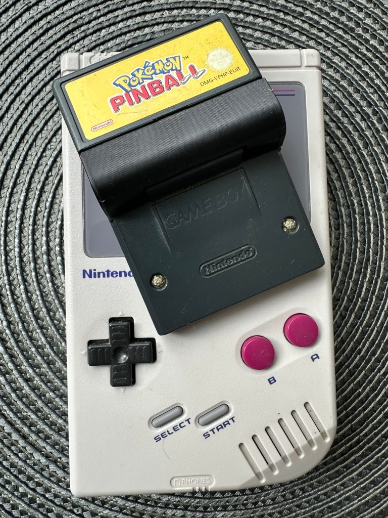
New 3D battery cover has arrived and this fits perfectly, no issues here.
Missing battery cover Clean and tidyNew 3D printed battery cover
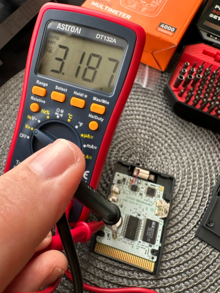
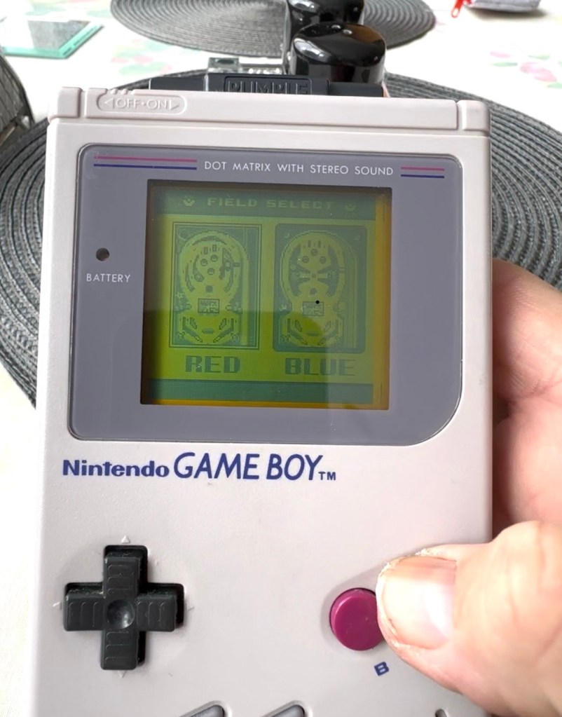
I’ve placed the unit into my GameBoy to check what occurs, and just as posted it does not progress beyond the Nintendo start up screen. I’ve opened the cartridge to do some basic checks and cleaning, the cartridge contacts have been cleaned using an eraser and some IPA, but in all honesty they were already pretty clean. I’ve checked the onboard battery and this is healthy at 3v as it should be. Cleaning competed, I recheck the game and the results are the same.
Game stops at this pointBoard levelBattery testedContacts cleaned
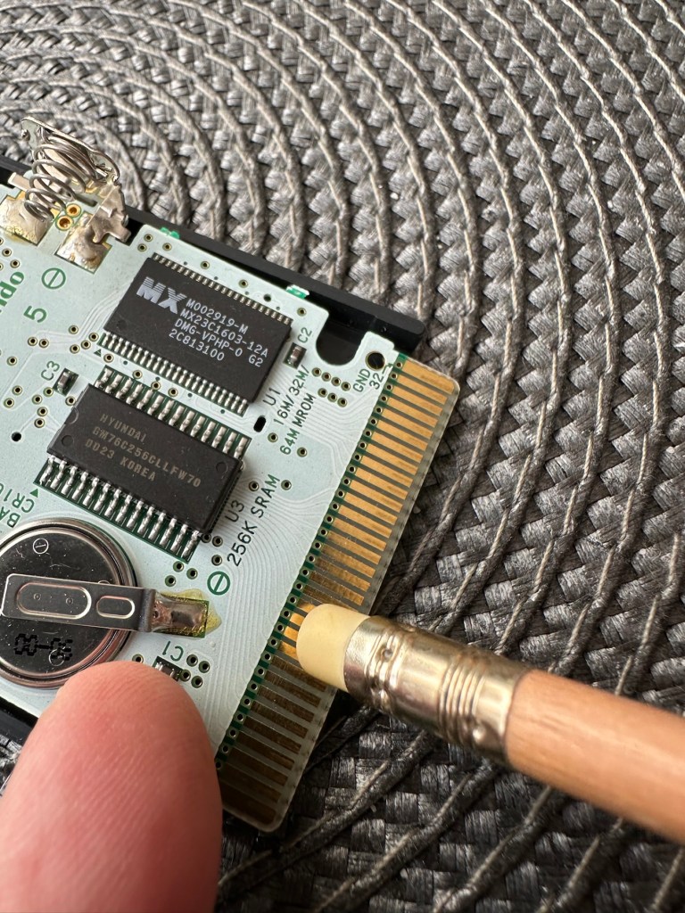
Next I’m going to reflow the joints on the ROM chip on the right hand side of the board, the one that has the letters MX on it. These pins or the ones on the RAM chip directly beside it are well known for having bad contacts and often need reflowing/tacking down. It’s something that seems to occur over a period of time on these game cartridges, just plain bad contacts.
ROM chip on the right with the RAM chip on the left, both are notorious for developing loose contacts
All items on the board have been reflowed using hot air, with extra attention being paid to the two chips described in the picture above. I removed the battery prior to doing this as the last thing you want is exploding batteries. With the battery back in place and the game now reassembled it’s now time to test.
And it works including the rumble pack feature.
Pokémon Working
I can only presume the hot air reflow has fixed an issue with joint continuity on one of these chips as expected. Excellent, another item has been saved from the bin and can now be added to my collection.
Game workingComplete with new 3D printed battery cover
Another little project to put to bed, there always seems to be an issue with these games after a good number of years where the solder joints just become unstable. I don’t know if it was the solder quality they used all those years ago or the heavy use and abuse the games endured during their hey day. At least we can fix them and ensure they are still good to go and enjoy for a few more years yet.
To build a usable, basic issue, medium format camera (Bronica SQ-A) from damaged items and spare parts, for as little outlay as possible and shoot one black and white, and one colour roll of film as proof of its successful completion.
Getting started:
Building a camera from damaged parts is no easy task when the name happens to be a high end brand and any parts that are available, are being snapped up by others to service their own stock or to break up for sellable parts. I’m going to keep a running total to try and build this as cheaply as possible, and to keep track of this total I’m going to use my trusty Psion Organiser II LZ from 1989 to keep a tally.
This may be a strange situation where Pt:2 and Pt:3 of this project gets published before Pt:1, quite simply Pt:1, the film back. needs a fair bit of work still doing to it.
Third purchase:
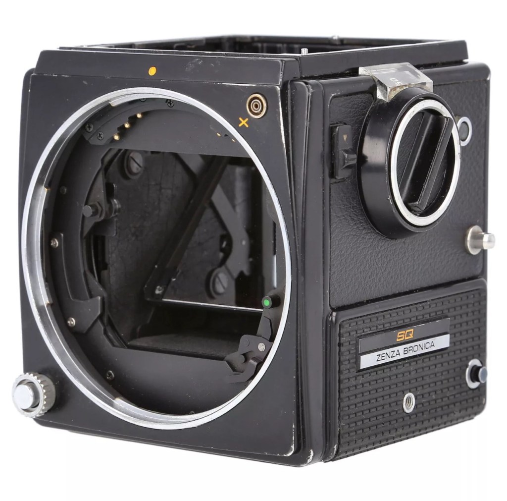
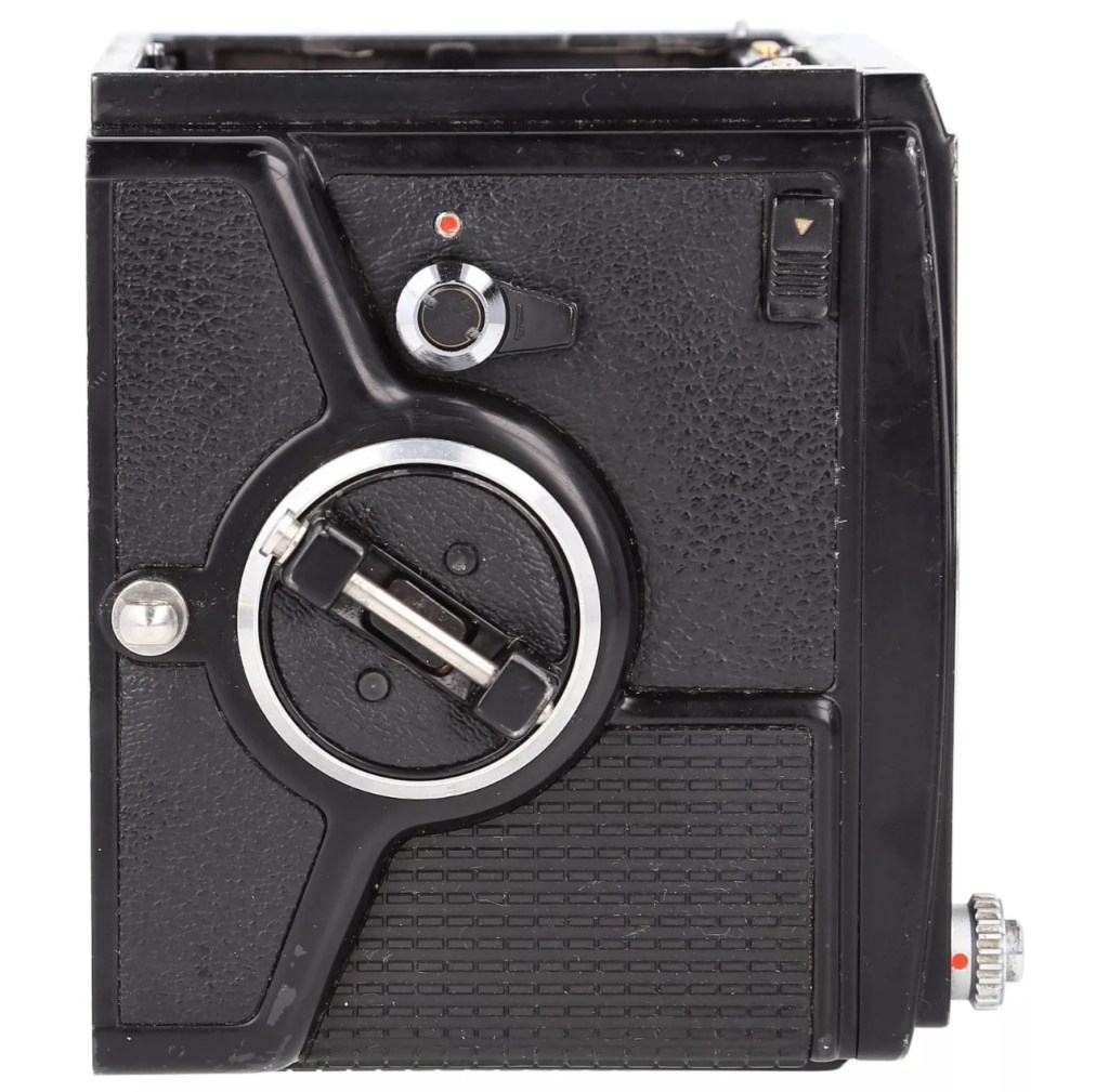
And the third purchase is for an SQ body. This appears to be well used, but appears to be in a working condition. Here’s what the listing stated:
Zenza Bronica SQ Body Only / Medium Format 6×6 Camera
Condition:
Used but still in good usable condition with usual signs of use – see photos for details please. Fully tested and in perfect working order. Supplied with: Camera body as pictured.
EBay
Now I’m happy with this purchase as well. Not quite the SQ-A I wanted but to be honest the only difference is mirror lock up and metering that I don’t really need so I can live with that, we all managed prior to the metering being done for us, I’m sure we will all survive now . (Oh how we have been pandered over the years)
The Bronica SQ body I have purchased
I’ve paid the grand total if £73:75GBP for this body including the postage. There are some bits I will require to complete the body, namely a focus screen and waist level finder that could be a bit pricey, and a winder for the body. Now, the winders are pathetically expensive at around £60 for a bit of plastic. I know a guy who 3D prints a good alternative for a fraction of the price. And that will be the route that I take.
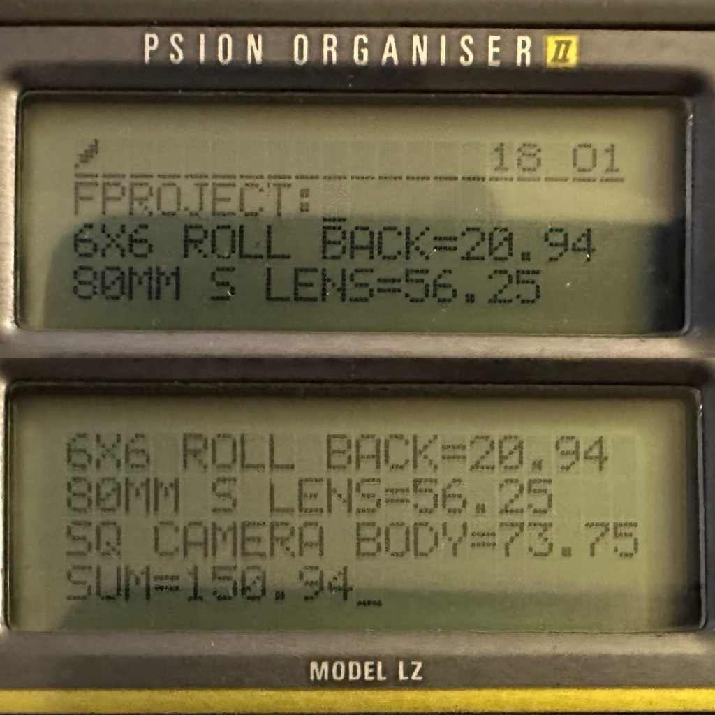
So over to my trusty old Psion II LZ for the running total for these first three items.
Current running total
So the total for these three items comes in at a total of £150:94GBP, and in Bronica terms this is extremely reasonable!
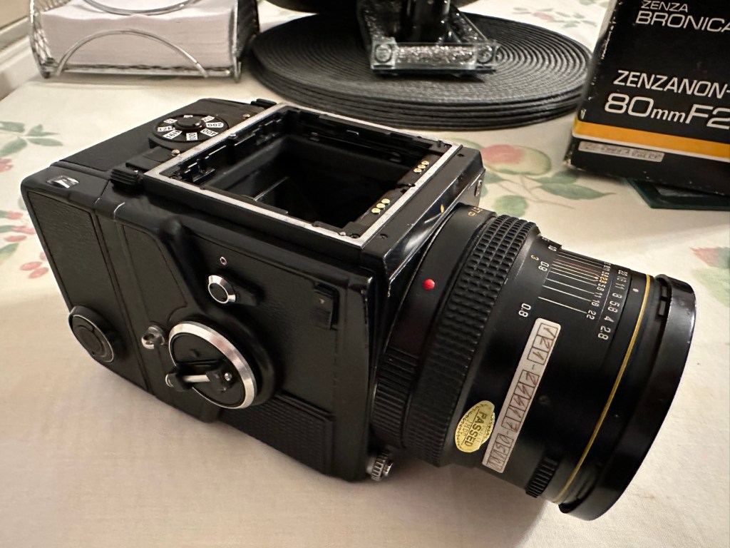
Assessment:
The parcel has arrived and yet again I’m really happy with this purchase. Very well packaged, a very faint age related mustiness that I guess should only be expected on an item that is now 45 years old. It seems to work just fine. I have connected the lens and that seems to be working ok, I just need to verify the shutter speeds are all correct. There is no battery in the base and this needs replacing as this is what controls the shutter speeds. Without the battery the mechanical shutter works, but only at a speed of 1/500 of a second. (Edit: the battery has arrived and after testing i can confirm that all speeds are operating as expected). The film back fits fine but I still have some work to do on that before I can say that this part is working ok. Overall I’m satisfied with what I have for the price I have paid.
No batteryNo winder A selection of covers for the sides, top and bottom are required
Repairs:
Not so much repairs but additions that are required, such as a crank winder arm and a focus screen, a new battery and a selection of covers to protect the central unit in transport. All horrendously over priced and i will deal with these items in Pt:4 of this project.
Outcome:
Current situation, looking good, smelling old. Not me, the camera 😂
We are almost there. The lens is fine, the main body is fine and just needs some final testing. The film cartridge is the item that needs the most attention and this will hopefully be finished when I have the new front plate that is being 3D printed. The next instalment will be just a tidy up with all the little bits I need to complete the build. These small pieces in Bronica terms are so bloody expensive, or should I say extortionate, can be obtained at a fraction of the cost elsewhere, you just need to shop around, if you are happy to have a non named spare part as a stand in. I’m happy with that as these parts have absolutely no effect on how the camera performs, and what we want to achieve at the end of this project, that being a well exposed two rolls of negatives that will produce a number of well presented photographs.
All good to go. Please keep an eye on the other blog posts that are coming regarding this project.


You must be logged in to post a comment.