

What the listing stated:
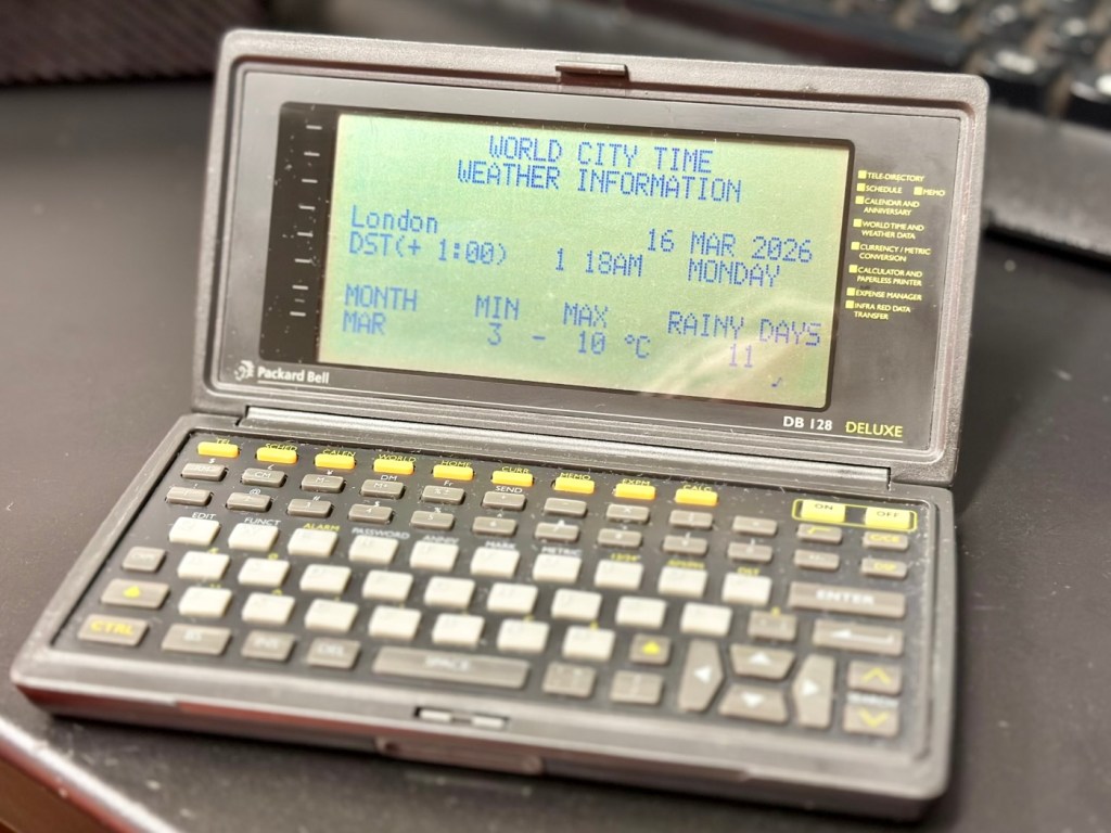
The Vintage Packard Bell DB128 Deluxe PDA Personal Organiser from 1992 is a charming piece of retro computing history. Manufactured by Packard Bell in China, this personal organiser is a single unit that serves as a reminder of the technology of the early 90s. With its vintage appeal, this item is ideal for collectors of vintage computing devices or those who appreciate the nostalgia of older electronics. The Packard Bell DB128 Deluxe PDA is a unique and rare find for those curious about the evolution of personal digital assistants. Needs new batteries at the very least. For repair or spares only
EBay
I love these postings on the selling sites, no actual real description of the state and condition of the unit you are purchasing, only a potted history of the item with the standard EBay get out excuse of “For repairs or spares only” I know, I can hear you saying, “ Well don’t buy it then – fool” and I agree with you wholeheartedly, I am a fool and I’ve brought it. But, it only cost me £3:30GBP so I’m happy with that, a good price for a bit of retro tech from 1992.
There is a good chance that this unit does only need some power, wouldn’t that be good? However it wouldn’t make very good copy on a site that looks at fixing other peoples castoffs, but I can happily go with the odd quick fix once in a while.
I love these old PDA devices from the 90s, and lots of people do, I guess some of us are still stuck in a period where technology was so wonderfully new and interestingly different. Whereas today everything is pretty much the same and controlled by a few massive organisations, when back in the 90s there were lots of different companies for you to choose your wears from.
I’ve certainly worked on a few on this site, just check the links on the home page to see what I have worked with.
If you are interested in the 90s PDA technology, may I suggest you look at this guys YouTube site. His name is Hugh and his channel is called Handheld Computing and he is a very interesting chap, and the technology is superb. Give him a visit.
Ok. Let’s read a little bit more about this unit:
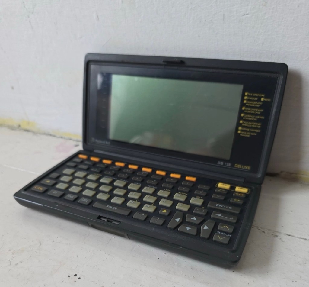
The Packard Bell DB128 (also known as the DB-128 or DB 1280 IR) is a vintage handheld personal organiser released in 1992. Also known as the Oregon Scientific DB-388P. It was designed as a compact digital databank to store contacts, manage schedules, and perform basic calculations.
Technical Specifications
The device features the following hardware details:
- Memory: 128 KB total memory, with a user-available area of 131,070 bytes.
- Display: An 8-line by 32-character dot-matrix screen.
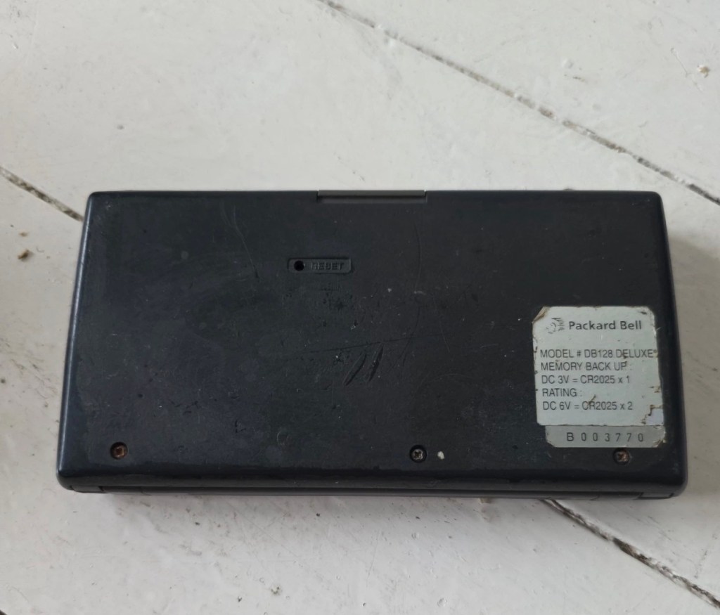
- Power: Operates on two or three CR-2025 or CR2032 button cell batteries, often with an additional battery for memory backup.
- Physical Dimensions: Approximately 15.8 x 8.2 x 2.3 cm, weighing about 252g.
- Connectivity: Data can be synchronised with a PC via a serial cable or infrared (IR) LEDs.
Core Functions
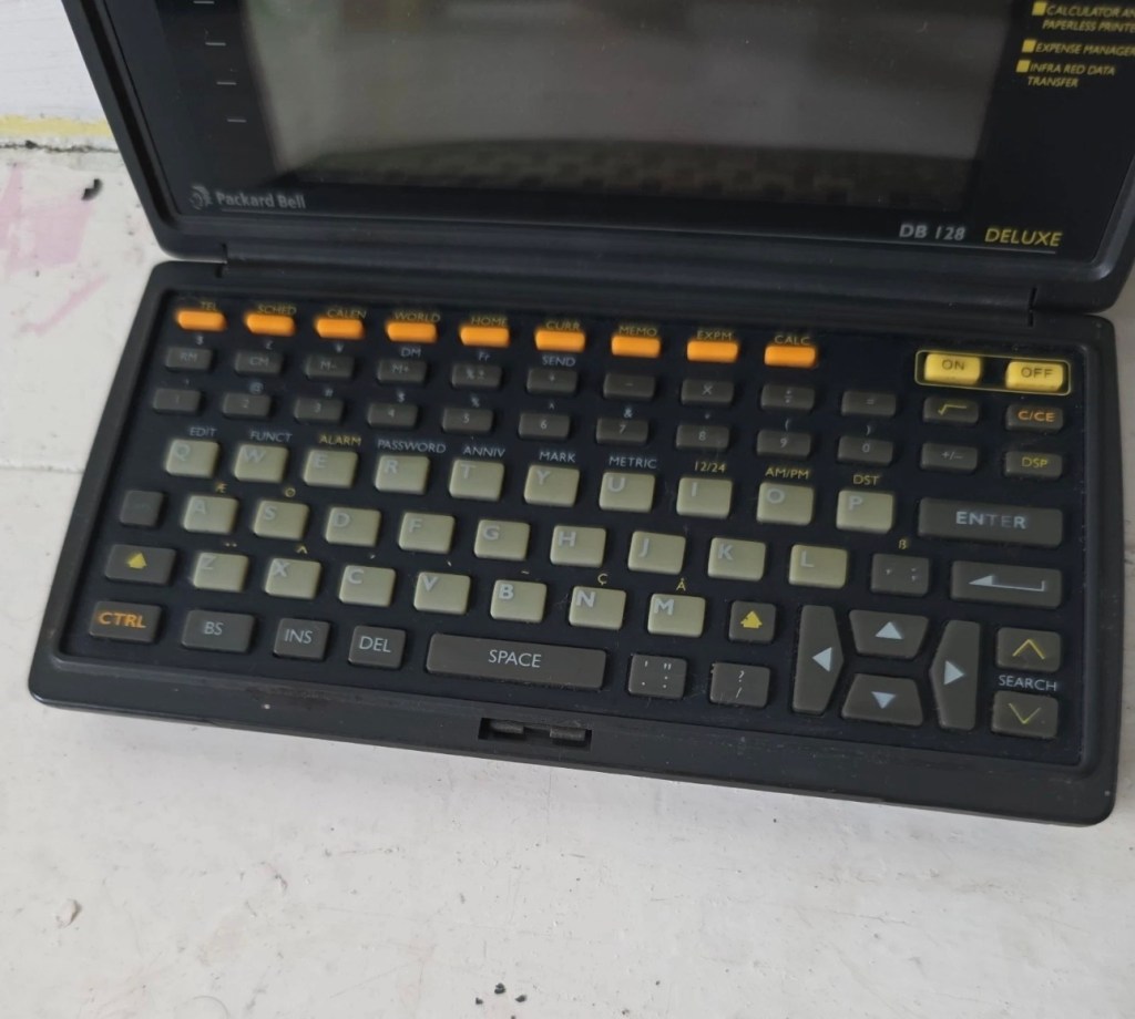
The DB128 includes several built-in applications for daily organisation:
- Phone Book: Stores multiple contact categories including names, fax, mobile, and email addresses.
- Scheduler: Features a calendar and appointment system with start/end times and audible or silent alarms.
- Utility Tools: Includes a 12-digit calculator, home and world clocks, currency/metric converters, and a memo/expense tracker.
- Security: Offers a password protection feature for sensitive data.
I just have to wait for its arrival now and I’m looking forward to that, I won’t speculate anymore about what might be, I best just wait for its arrival to carry out a suitable assessment.
Assessment:
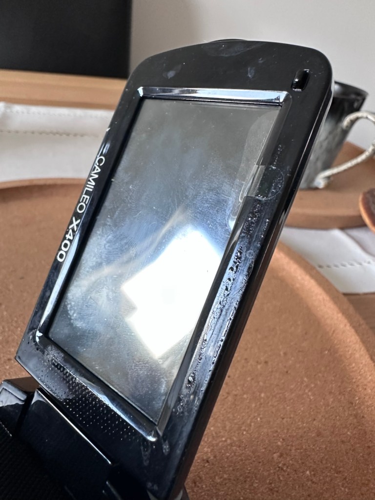
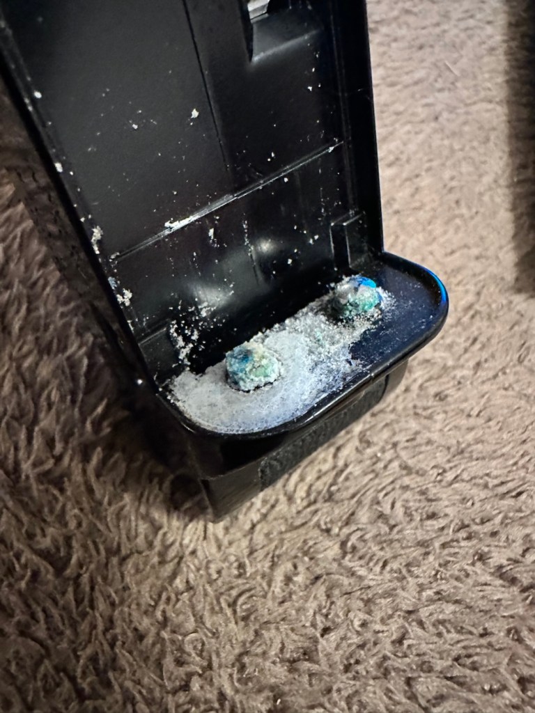
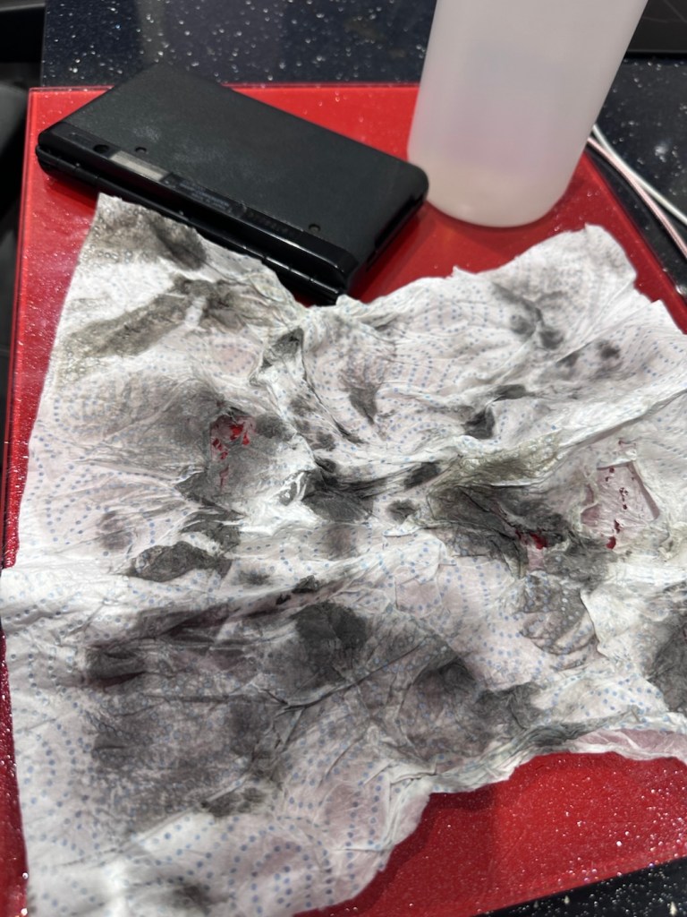
It’s arrived and good god, it looks as if it’s been stored in a vacuum cleaner bag 🤦♂️ it’s utterly filthy, funny how none of the original photos showed this isn’t it? I don’t believe this is the same unit as was in the original posting.
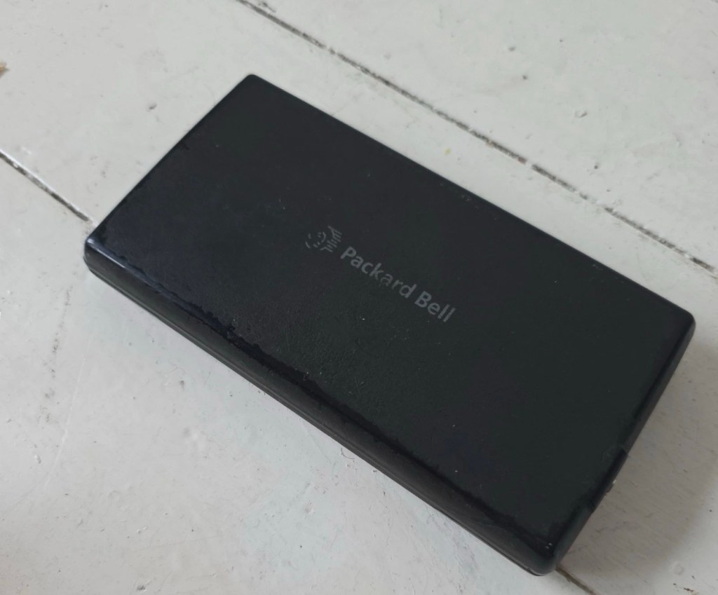
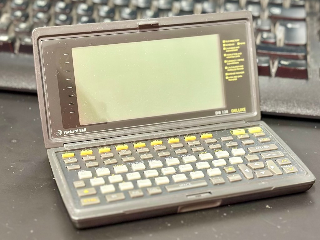
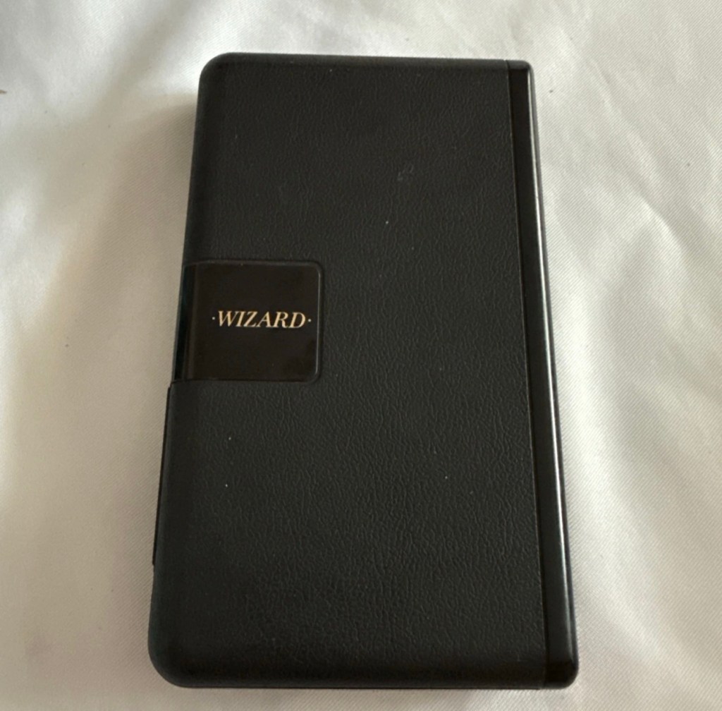
If I’d have taken this into the house with the wife present, i think she’d have murdered me, or at least severely injured me one way or another… So that is why you will see that these pictures were taken at the kitchen sink, the first thing this unit received was a clean with a cloth and warm water. After that it’s had a good polish and it is now nice and clean. Now it can come further into the house, into my domain!
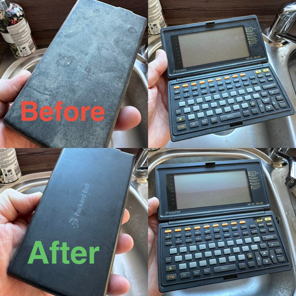
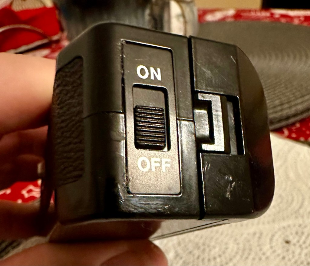
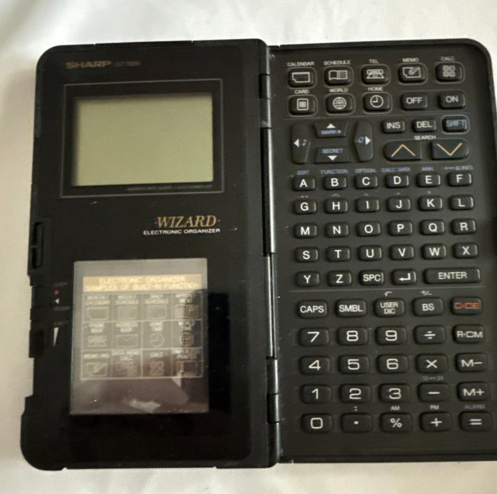
Now the unit is tidy, everything is as it should be, and the screen is in a good condition barring a few minor age related scuffs. It’s dead, and that’s to be expected, I’m just hoping there are no major surprises awaiting me when I get the back off to have a check inside.
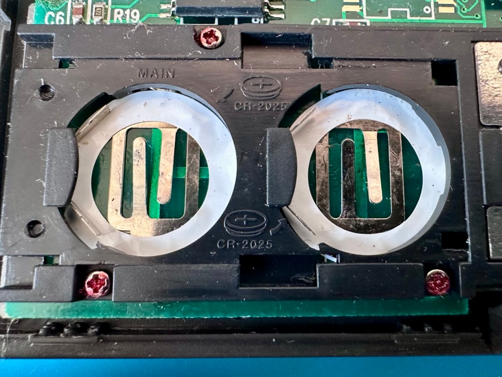
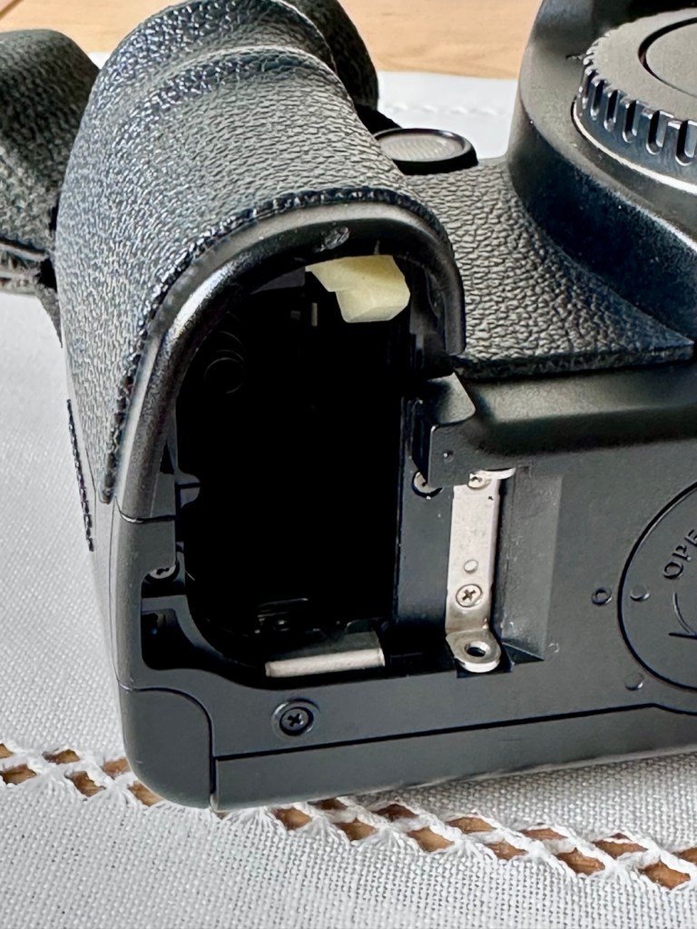
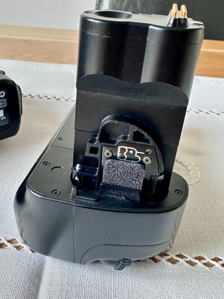
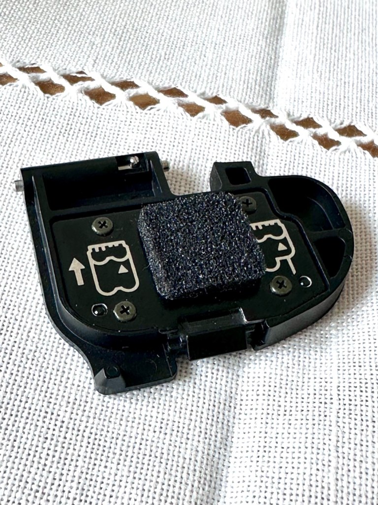
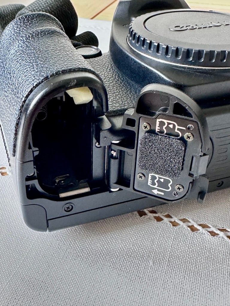
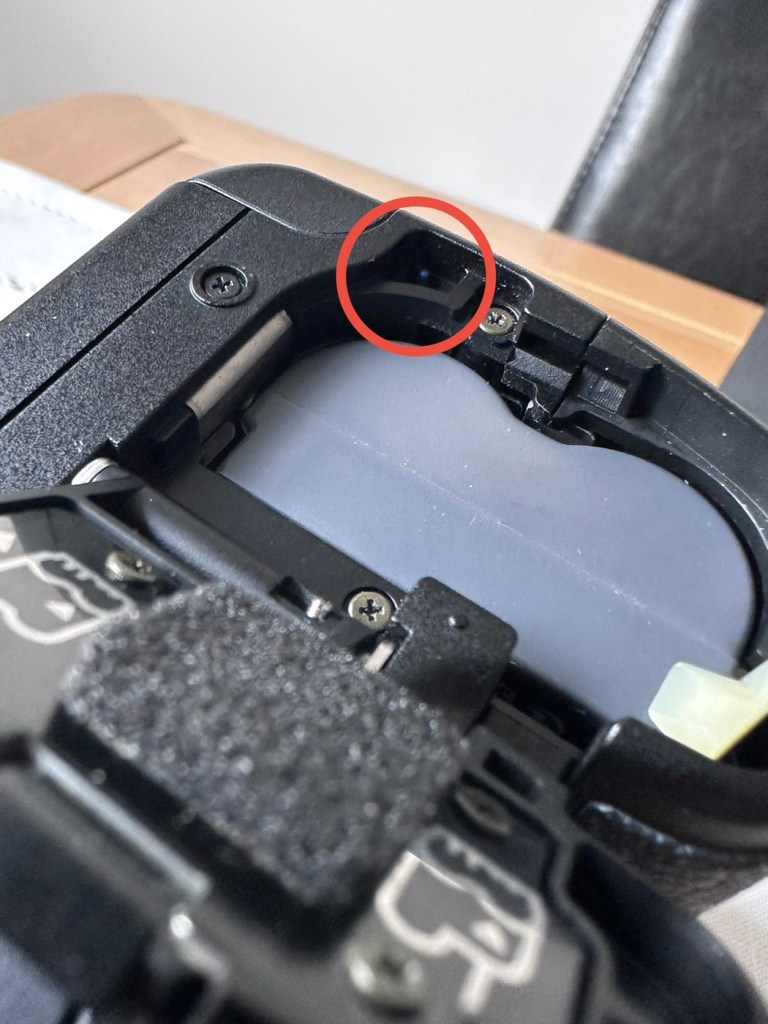
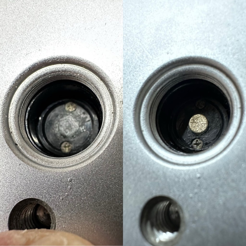
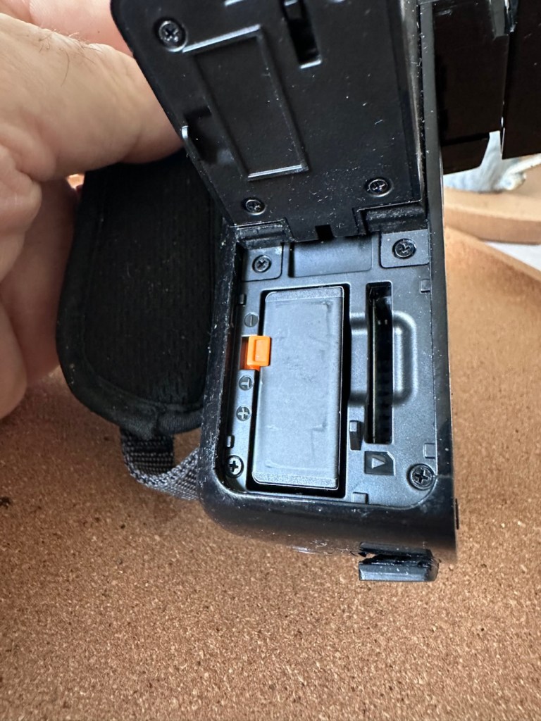
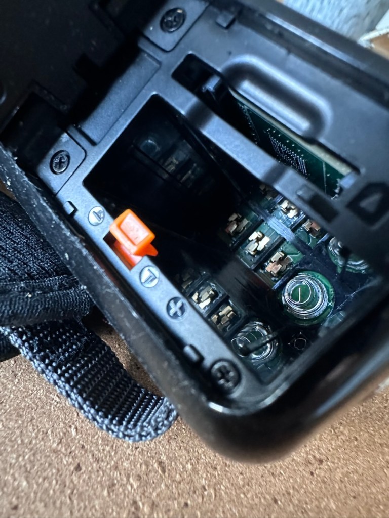
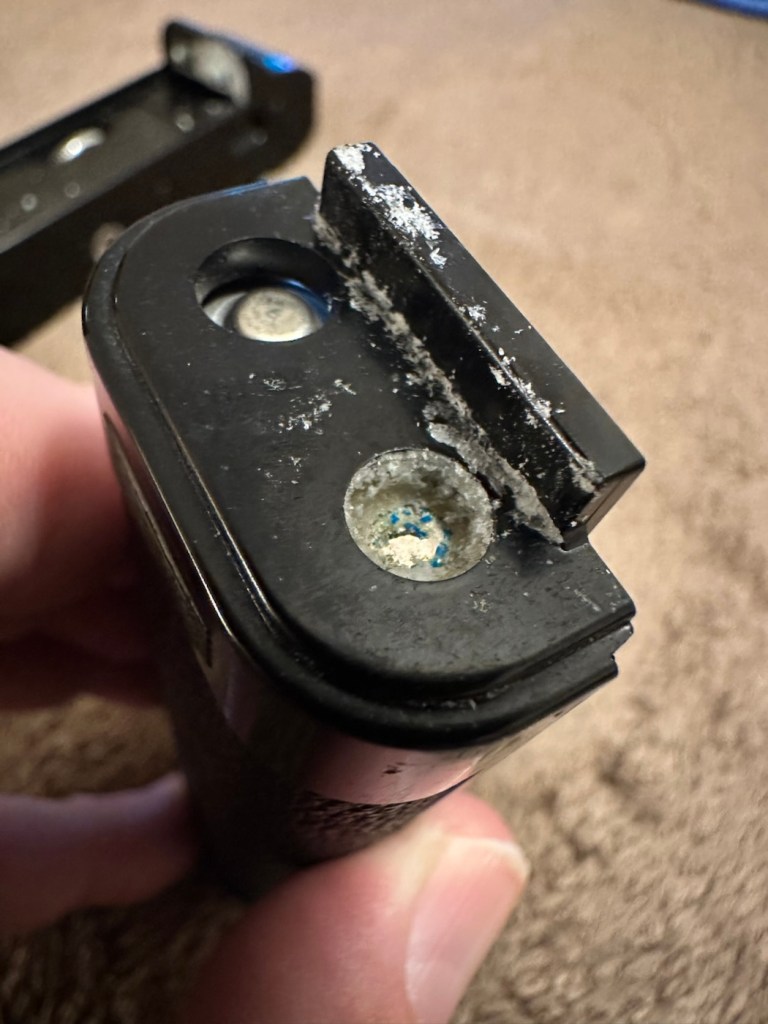
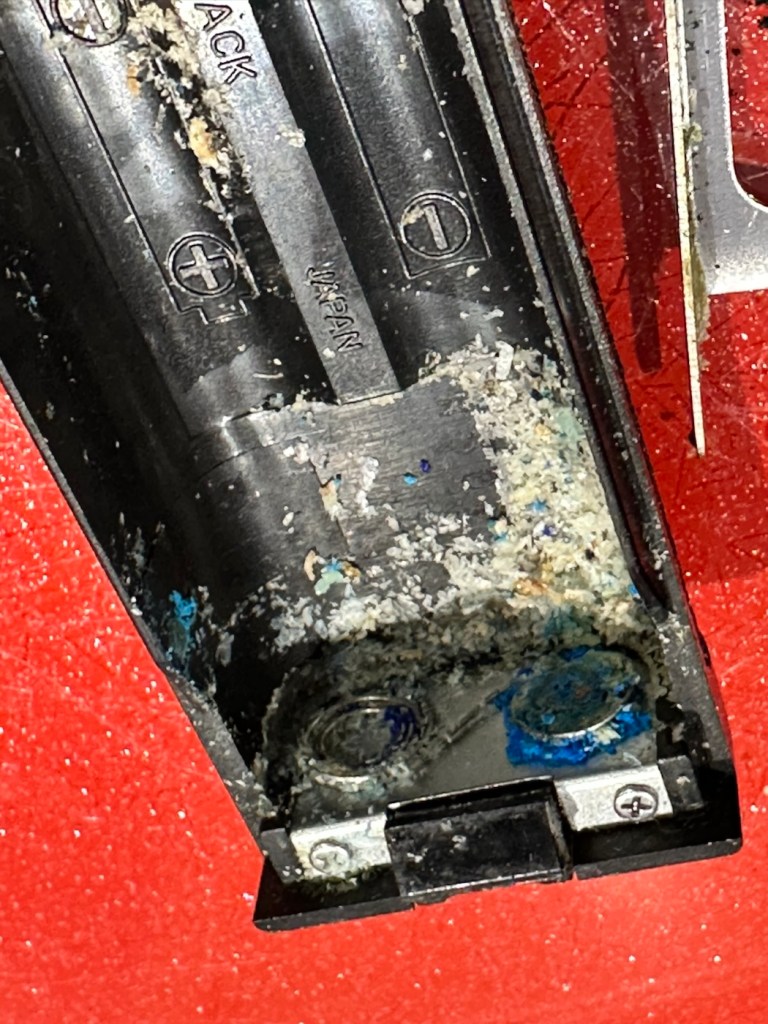
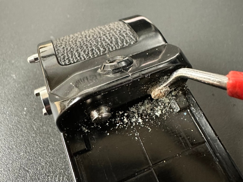
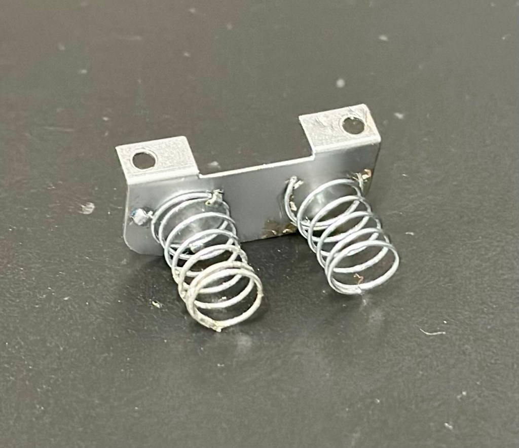
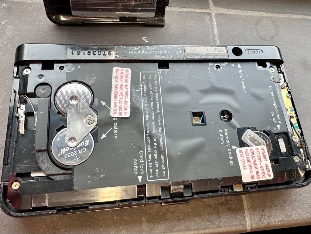
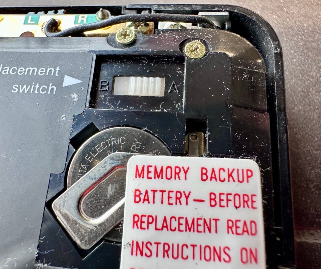
Three screws later and the back is off. All three batteries are still in place, all very dead but fortunately there is no corrosion or battery leakage. All that is visible is some age related tarnishing of the battery enclosure, this however has no effect on the board or electronics and will tidy up with a little brush over with some relevant cleaning solution.
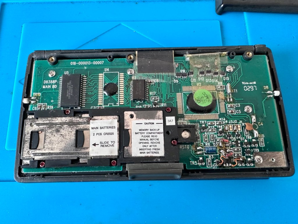
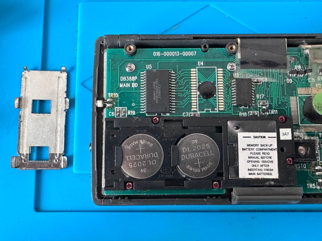
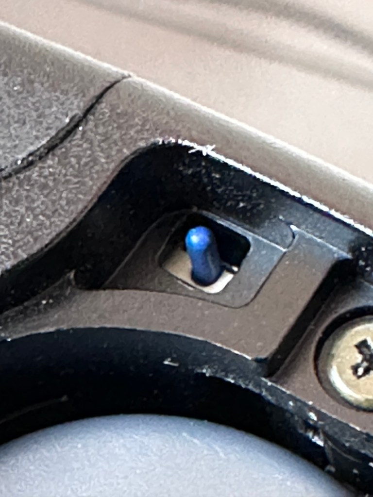
With these little database units you were always supposed to change the two main batteries and get them in place before even considering removal of the single back up battery. This was purely to ensure that saved data was not erased from the memory bank, however as all these batteries are dead, it’s no real issue here. The backup battery is protected with a single screw that needs to be removed to allow access. This unit was able to transmit and receive data using infrared technology. If you look at the picture above with the case off, on the left and the right of the chassis you will see a white diode component, these are the infrared transmitter and receiver parts of the data transfer circuit.
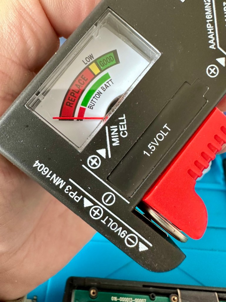
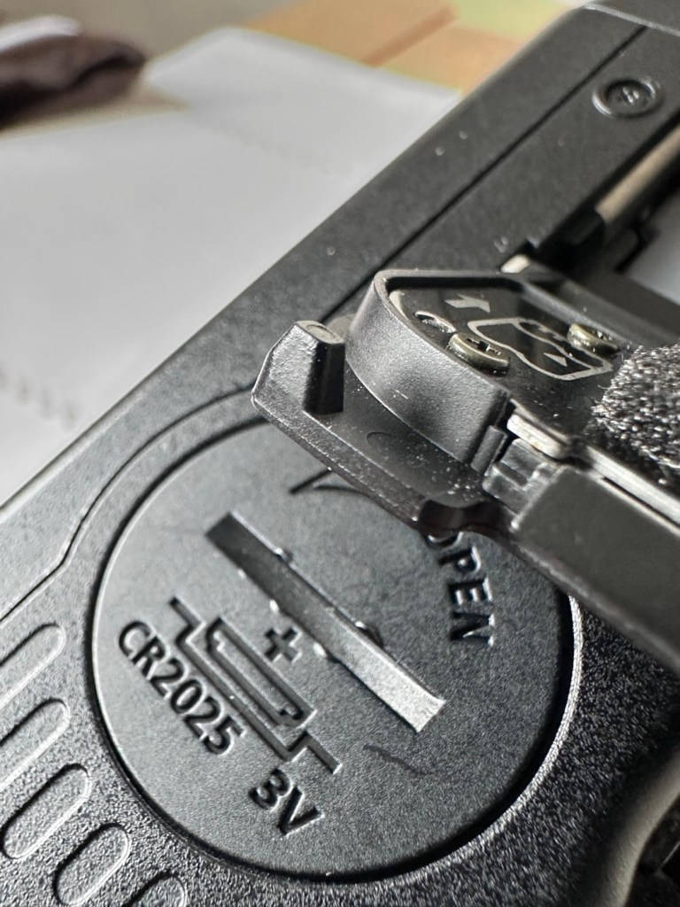
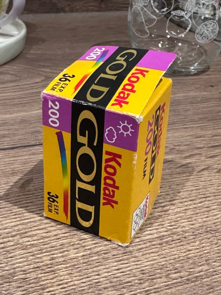
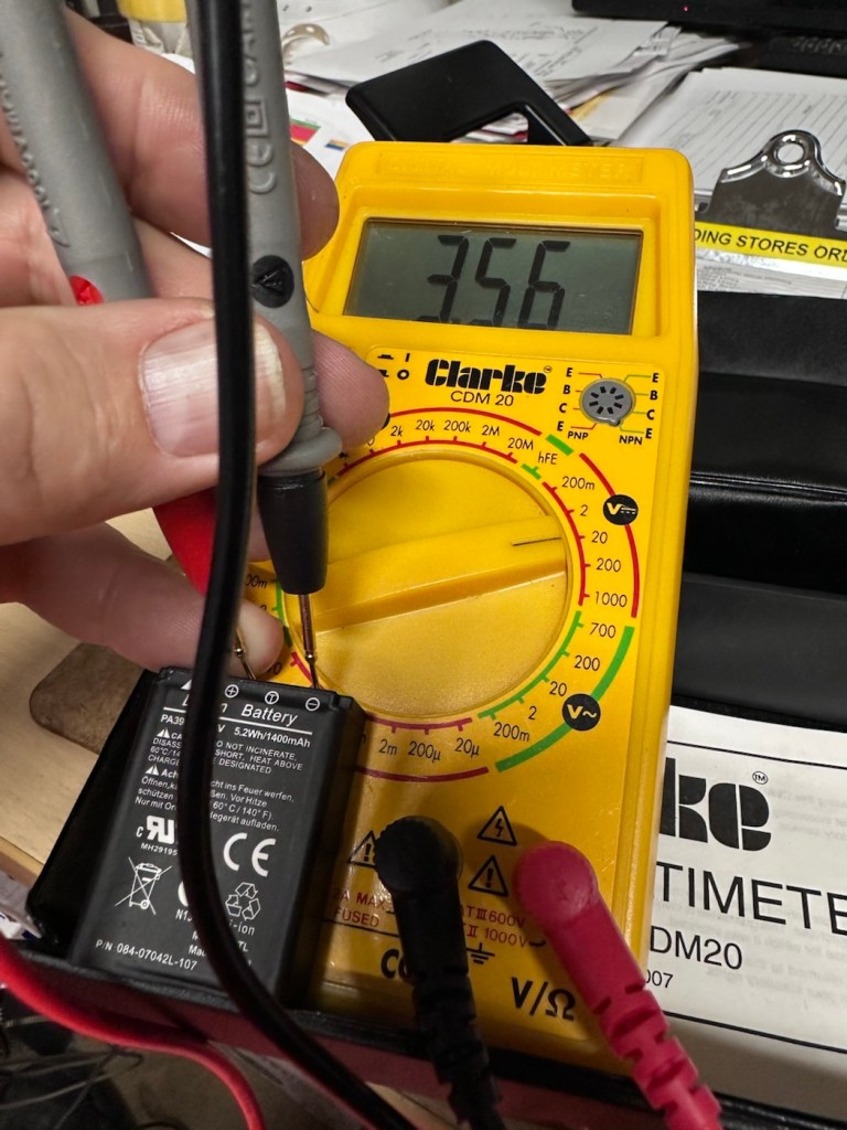
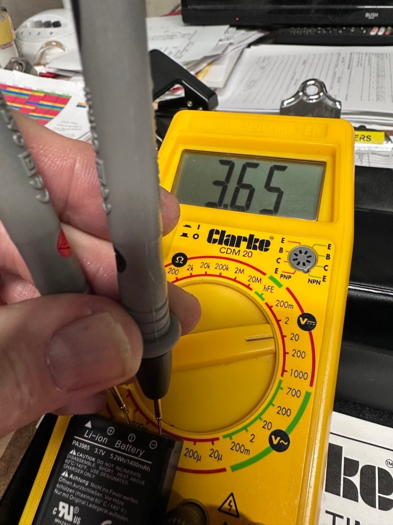
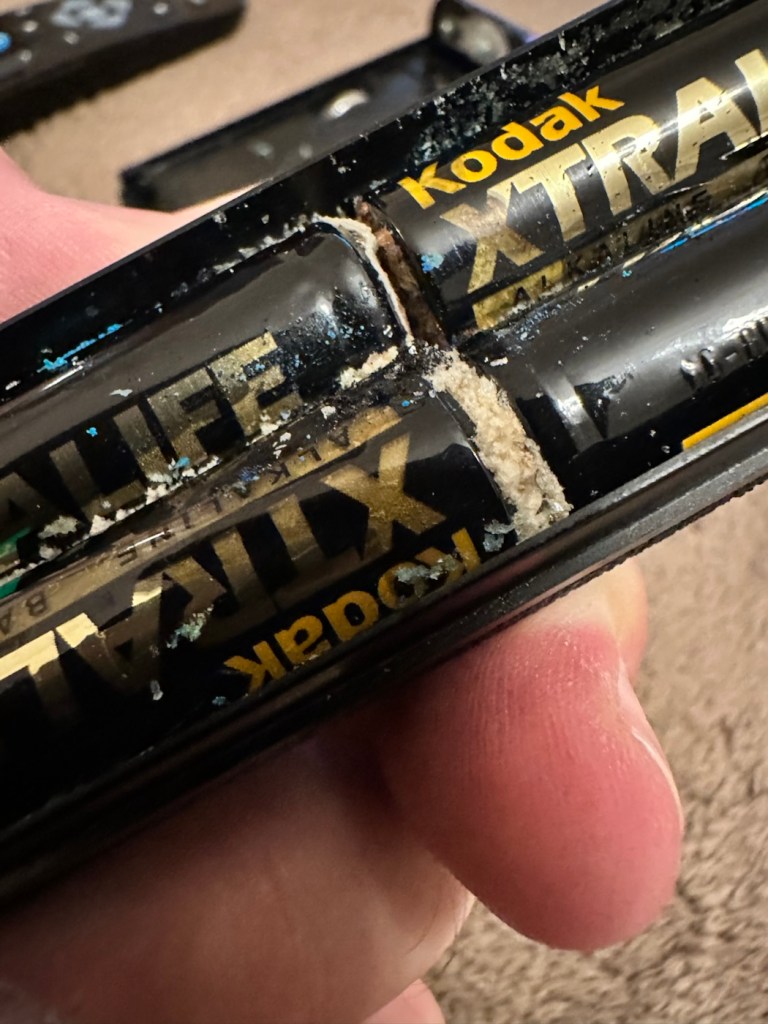
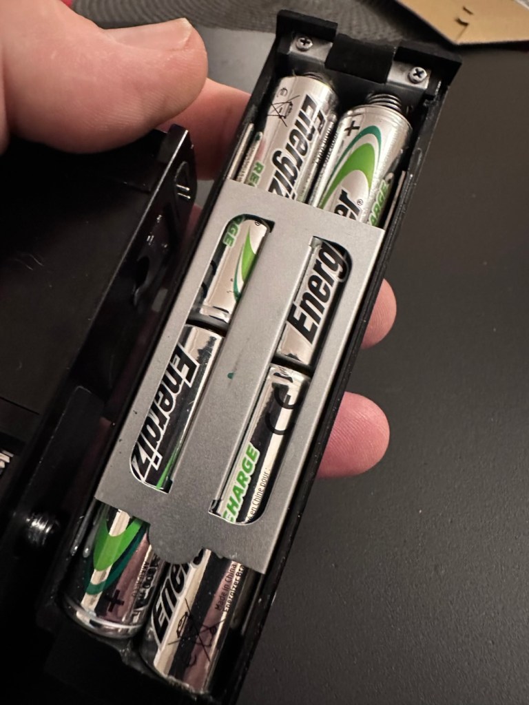
The batteries needed within this unit are CR2025 mini cell batteries, I currently only have CR2032 batteries, they look the same but just what is the difference? Thanks for asking, i will now explain.
- The letter “C” refers to the batteries chemical compound, “Lithium” or to be absolutely precise “Lithium Manganese Dioxide”.
- The letter “R” refers to the battery shape, in this case its “Round”.
- The numbers “20” refer to its diameter in millimetres in this case “20mm”.
- The numbers “25 or 32” refer to the “Height or Thickness” of the battery in millimetres “2.5 or 3.2”
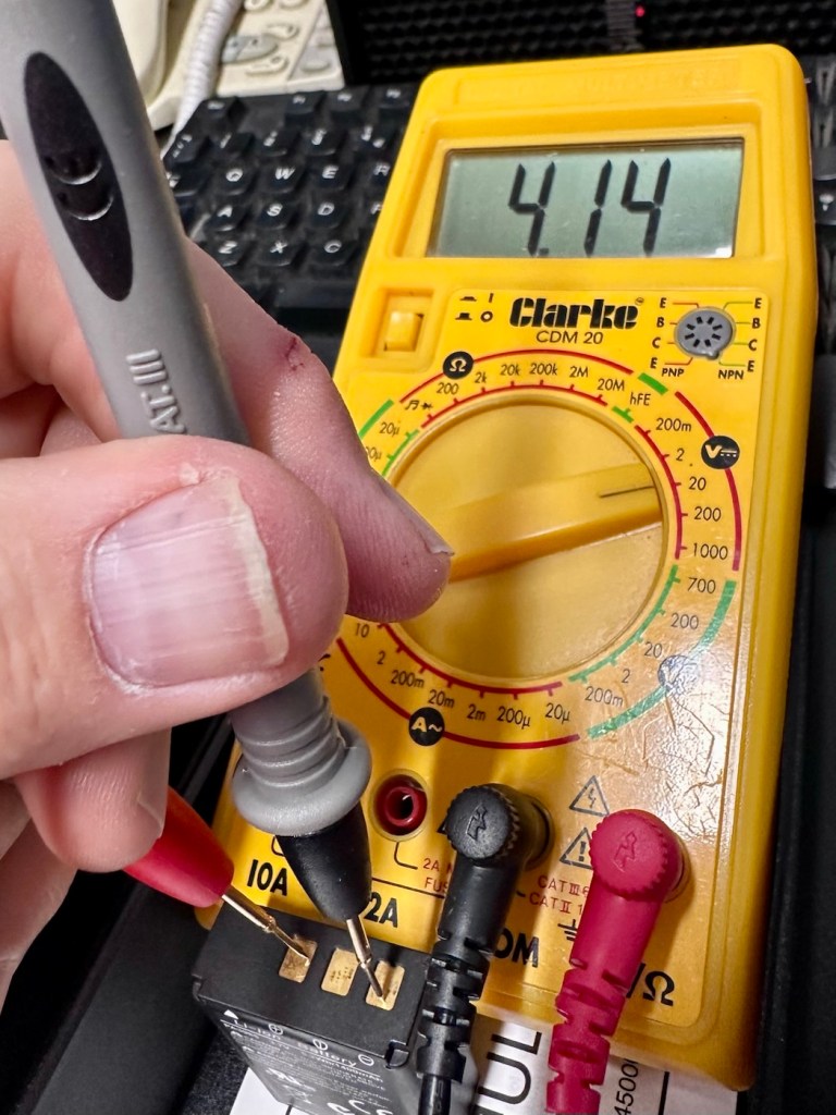
And there endeth the lesson for today. So, in all aspects the batteries are exactly the same, 3 volts, but there is just a slight variation of 7/10 of a mm in thickness. In some cases this is not an issue where there might be that slight bit of space for you to use an alternative cell, however in the case where tolerances are tight such as in watch mechanisms, that tiny difference in size may not allow you to reassemble the backplate to the watch. I hope that clears up the difference between the two coin cell letter and number allocations.
I can use CR2032 batteries in this unit as there is the space. I have some CR2025 batteries on order, so I will comply with the original standard when they arrive. But for the purpose of testing further, the CR2032 batteries will suffice.
Repair:
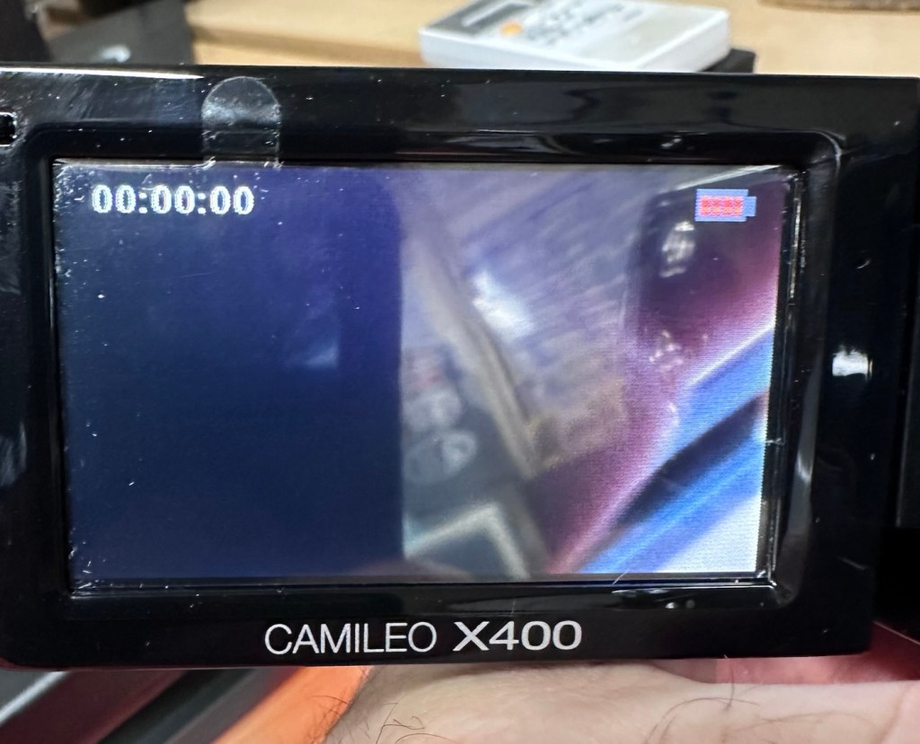
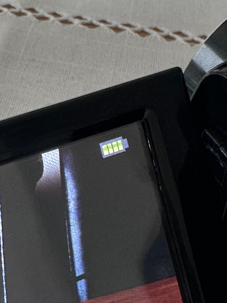
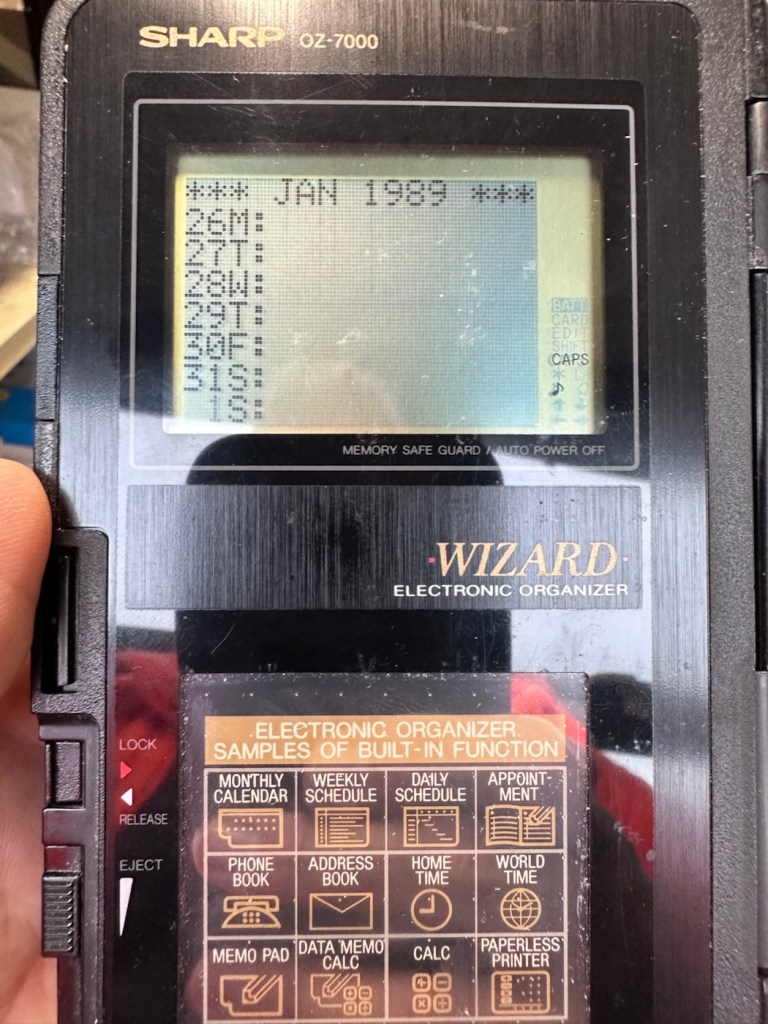
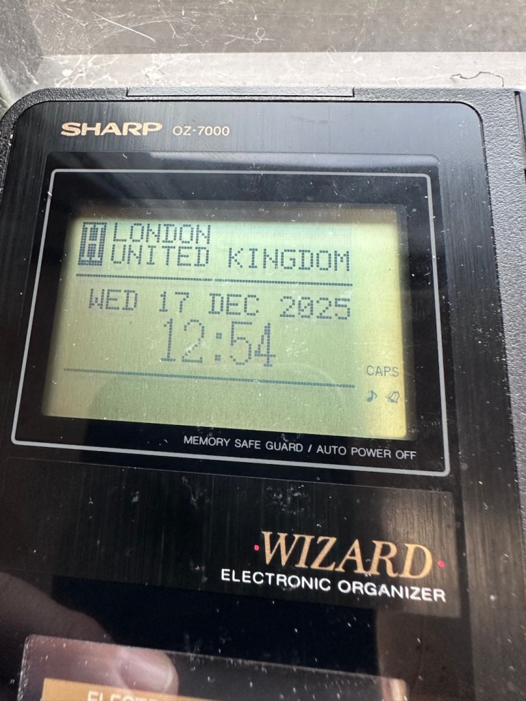
What repair, to be honest it’s been more of a clean, I’ve cleaned the inside circuit board with some IPA and a brush and cleaned all the crevices with a pick and finished off the outer case with a good coat of antiseptic cleaner and polish. I have inserted the three required batteries and switched the unit on.
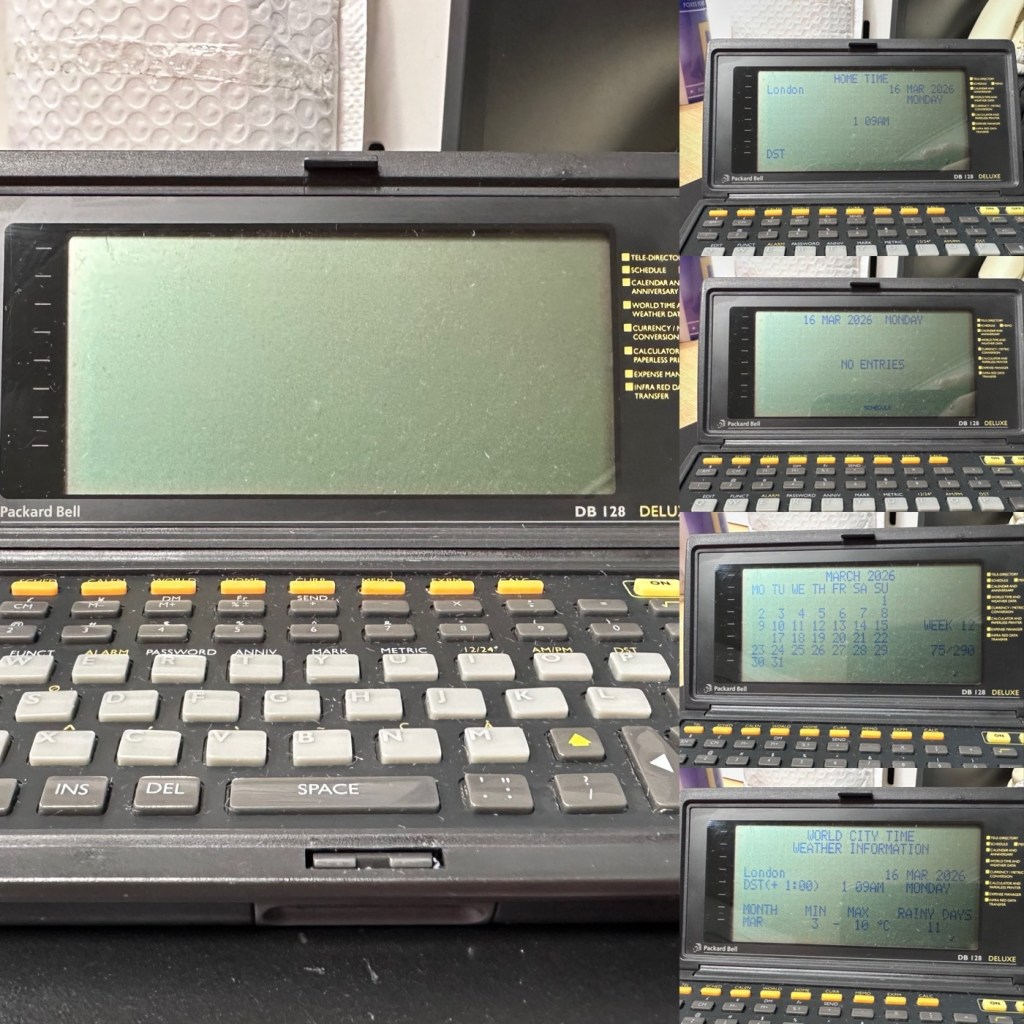
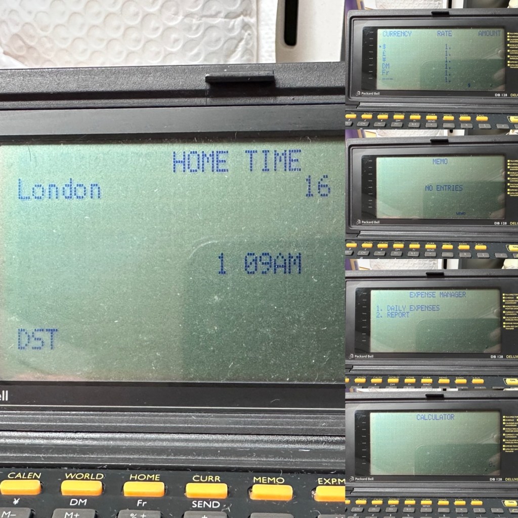
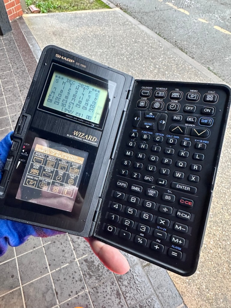
Not a great deal more I can say. It’s clean, in fact it’s very clean, and fully functional.
Result:
It’s 34 years old, it’s been discarded, put aside for disposal, given one last chance in its chequered life and I purchased it for £3:30GBP. It’s now revitalised, cleaned inside and out and been given a new lease of life. One of those very simple clean and repairs that anyone can do. And another item is saved from landfill.
This will now be added to my ever growing collection of old PDA equipment from the 90s, a collection that is starting to grow at quite a considerable rate. I have a few more little projects similar to this in the pipeline, quite similar to this one but requiring quite a bit more attention. Please keep passing by to keep up to date with these “mini” projects.
Once again, thank you for passing by, it is always very much appreciated.


You must be logged in to post a comment.