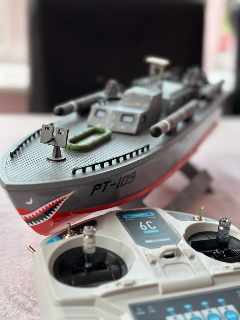
Today 16th June 2025 and this boat that I was gifted for my last Birthday back in Nov 2024, finally underwent proper trials on water, and thankfully after all the issues experienced during the building process it came through them with flying colours. There are a few little tweaks to do as a result of the maiden voyage, but this will only go towards making it a far better and less stressful task on future excursions. Boy was i nervy about today, what with all my family watching.
A nervous owner placing his boat on the lake…
And off we go…slowly
I only have the one battery for the boat so time was limited, and I probably managed about 15 minutes with it nutting about, before it stopped and had to be rescued by my Brother in laws boat that just happens to be a tug, a seaborne version of the RAC.
Luckily the seaborne version of the RAC were on hand
Anyway prior to that minor mishap the boat performed quite well, the motor is hellishly powerful and I thought it would go either of two ways. Either it would launch itself out of the water like a missile or it would go nose first into a deep dive towards the bottom of the lake. Luckily it did neither, however I did learn that turning at speed is liable to capsize the boat, so care needed to be taken when performing turns under power.
And she works…..
As usual I have learned a lot. It needs some minor tweaks such as a better centralisation of the radio gear in the hull, it needs some Baffles to be put in around the front deck where the hull and the superstructure join, to prevent water ingress at speed. The front does sit low in the water but at speed the contours on the hull do create lift, and this does work very well, so I am particularly happy with this.
A great day out, at the start of the holiday, and the fact I didn’t have to go wading to rescue a failed boat is also an added bonus. Really looking forward to showing the videos and pictures to the elderly friend who purchased this fantastic gift for me. They will be as pleased as punch, as they know about all the hard work and care that has gone into getting this project finished.
Thanks for following the journey with this project. As always it is very much appreciated.
How it looked in the last blog post prior to finishing
This post covers the finishing, that is the priming, painting and installation of the radio gear to complete the build of this wooden model boat.
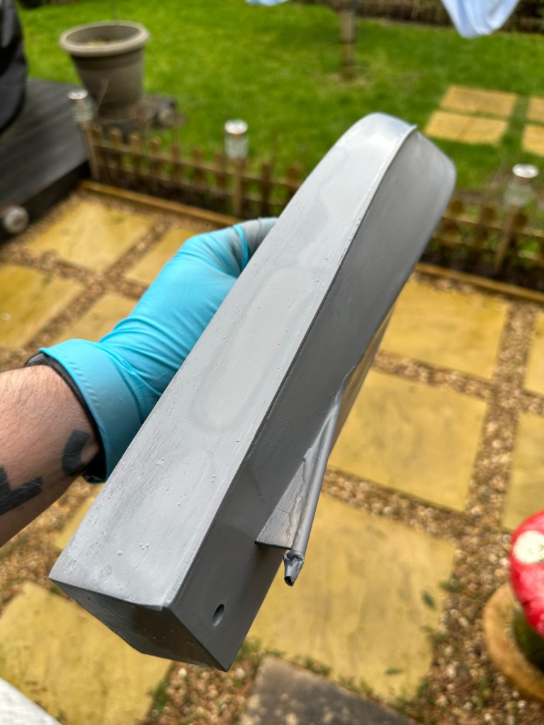
I have to give a couple of coats of high build primer to the hull and deck sections, and for this task I will be using Guild lane high build primer.
This will seal the already sand sealed wood and give it a good foundation for the final paint application. I will give a good initial coat, lightly sand and fill any imperfections and then give a final second coat prior to choosing the colour scheme I’d like for this boat.
Today I have given the first two coats of primer to the hull and deck, and I’ve primed all of the cabins and guns and torpedos in preparation of individually painting them. I need to do a light sand on the hull and I believe a third coat will then suffice.
All deck weapons primed and painted
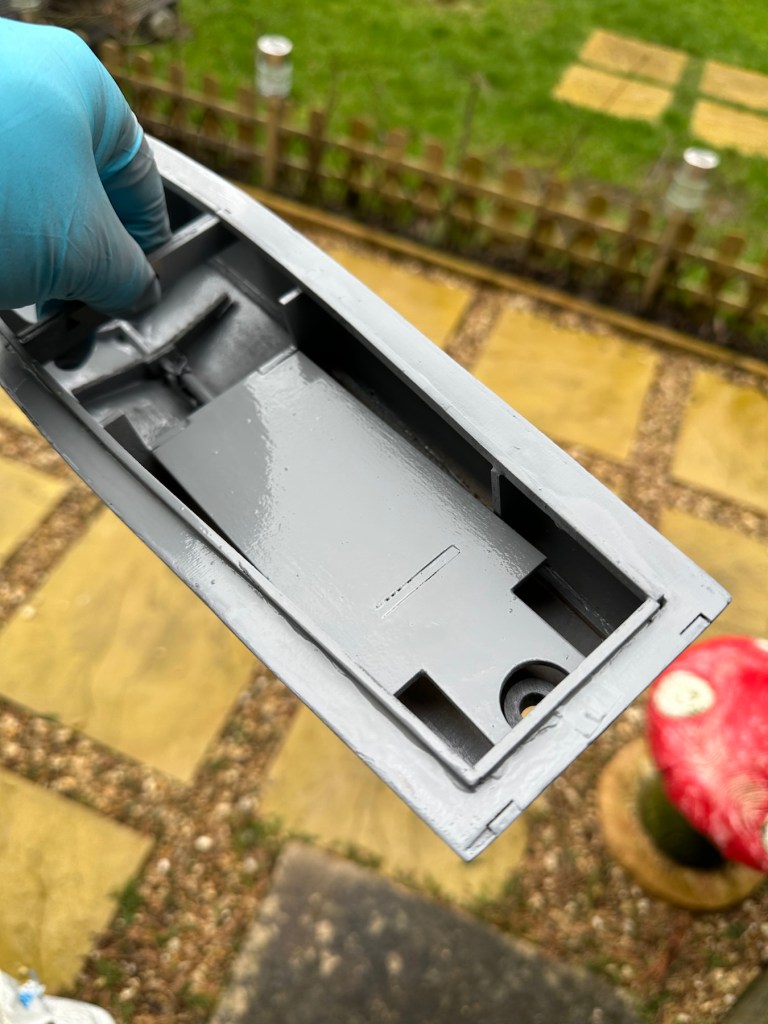
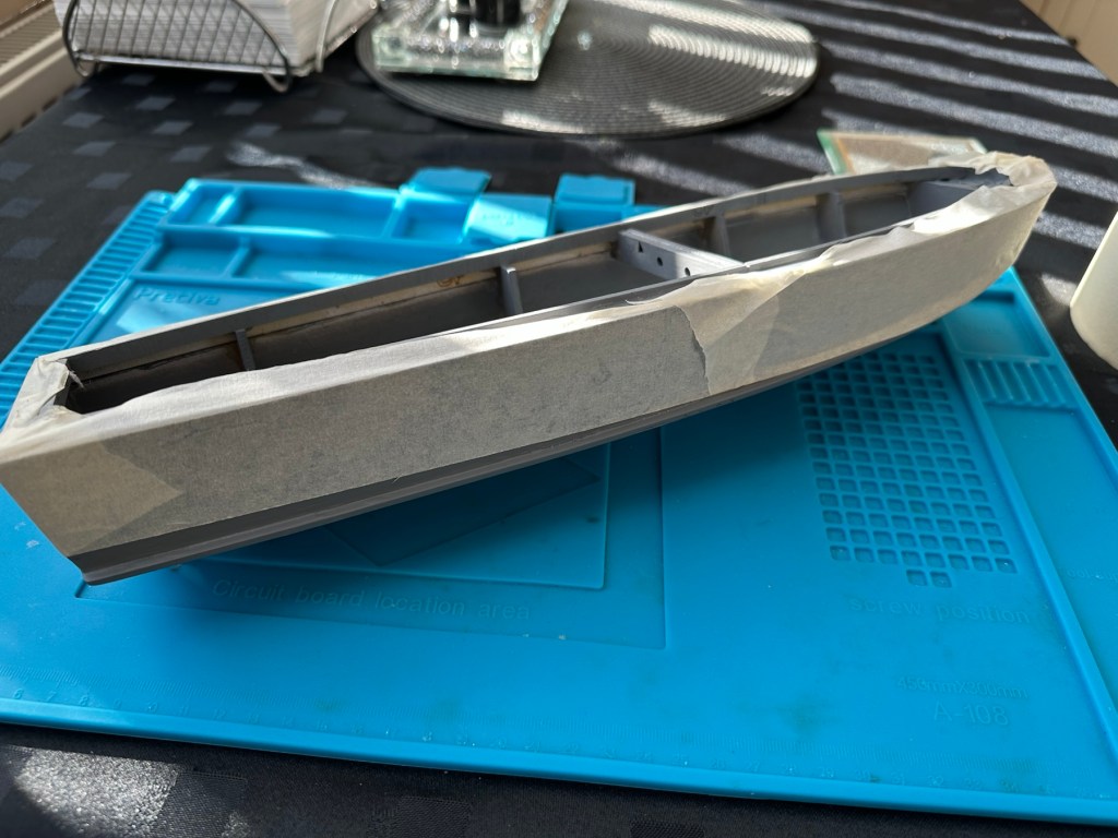
HullInner battery plateInside hull
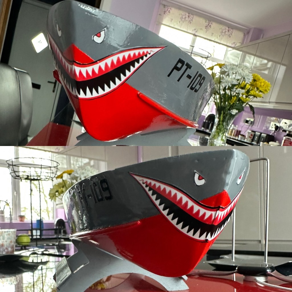
I’ve given a light sanding to a couple of spots on the hull, I’ve filled a couple of tiny holes, sanded again then re sprayed the hull. I’m happy with how it looks at present. I’m not following a traditional paint scheme, so there will be no comparison to its original appearance. I’ve hand painted some of the deck fittings, put in the cabin windows and started to fix these items into place.
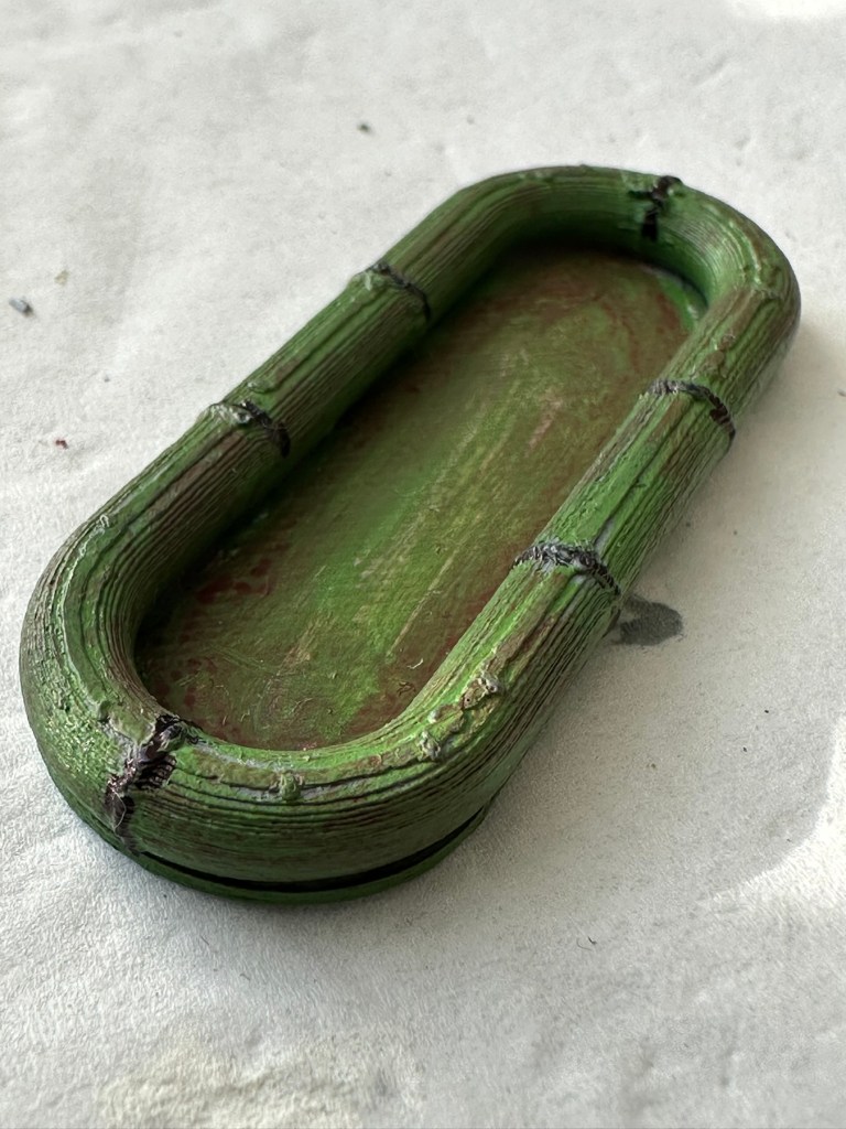
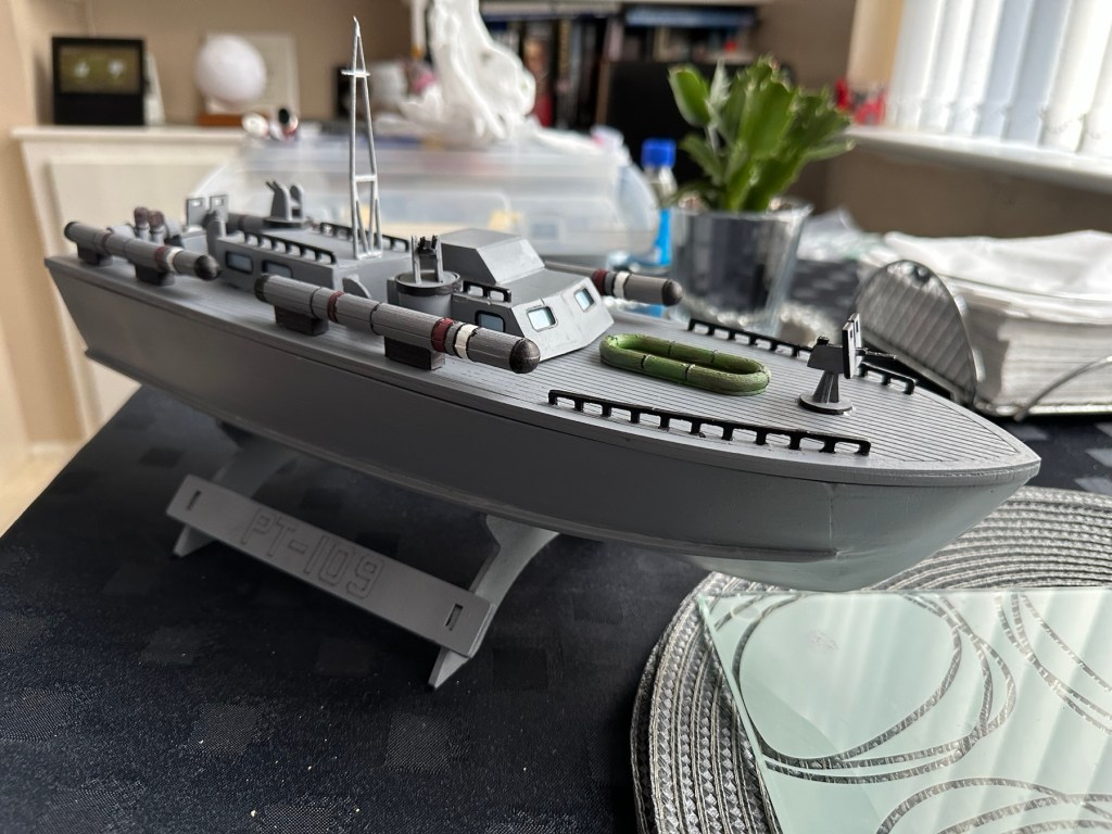
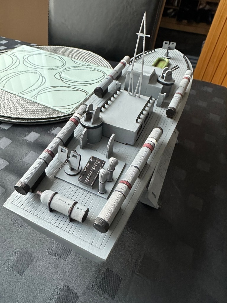
Hull painted deck fittings to be put in place. Deck dinghy painted and weathered Super structure addedDinghy placed Weaponry attached
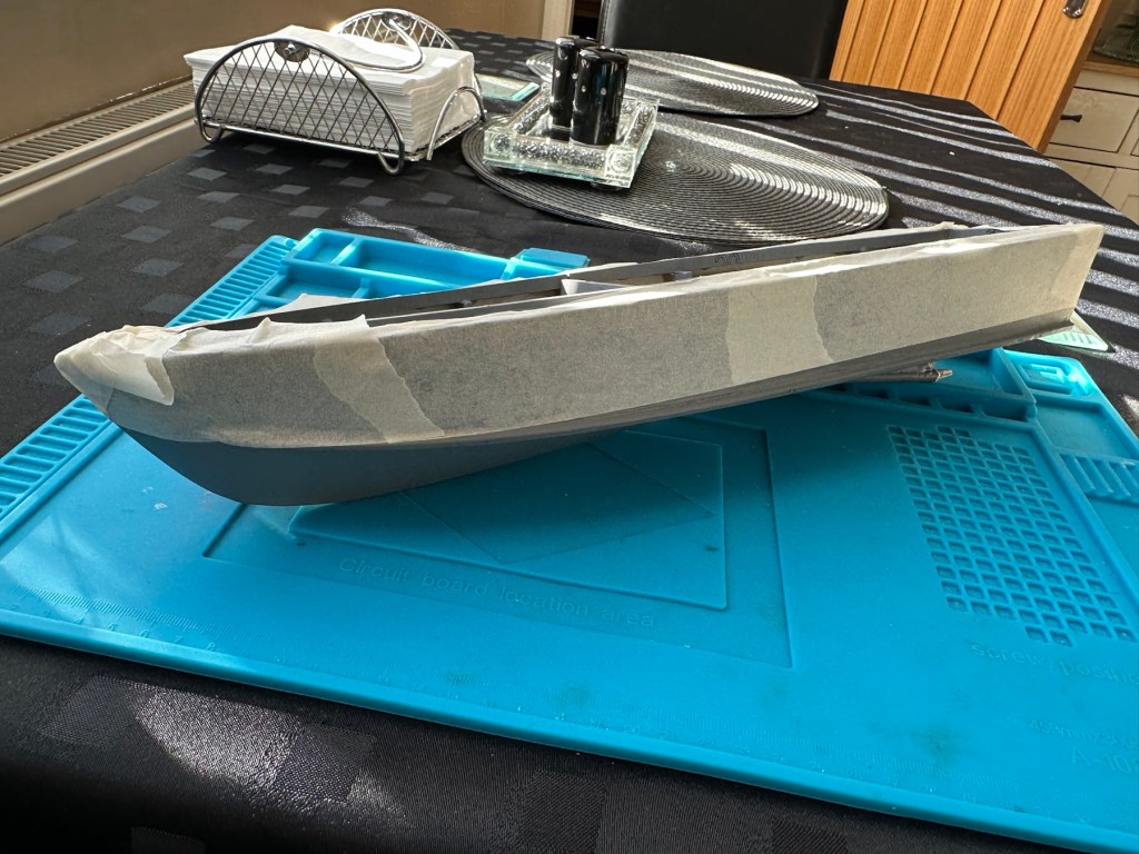
I’m just awaiting some red paint to finish the hull, then I can get some decals in place. Then I can seal it all to finish the exterior of the model and then I can concentrate on setting the motor and the internal electrical elements up. Next I have to mask the area of the hull that I will paint red, I’ll do this now before the paint arrives as it just has to be right first time. I don’t want to be touching up too much if I can help it.
Masking of the upper deck in preparation for a red belly
I’ve made a pair of support struts out of balsa that sit behind the aerial, I’ve changed this area completely as it was too delicate and would have been a nightmare to transport. I’ve built a modern style array for a radar, I know it’s not going with tradition but again it makes for easier transport and reduces the need for repairs on the go.
First coat with mask in place
I’ve done the first three coats of red paint for the waterline, I’m going to leave this 24hrs now before I peel back the masking to reveal what mess I have underneath. Fingers crossed on this 🤞
Masking tape all removed
Fingers now uncrossed I’m really pleased with the outcome. The masking tape has been all removed and we now have a nice crisp line around where the red joins the grey. There’s some like marking up by the front end that believe it or not are finger nail marks when I was applying the mask. I’m not worried about this though as I have some sharks teeth decals coming that should cover this area. One of the little additions I wanted to make, to put my own mark on the build. Once all the decals are placed I will then give a final coat of a yacht varnish to seal all this work. I’m going to test a small area first as the last thing I want is for all this hard work to run into a gooey mess.
I have done the tests and commenced with coat one of the varnish. It looks gorgeous. Im probably going to do a further two light coats and that will be the hull complete. I haven’t put the decals on yet, I will probably do that prior to putting on the finishing coat.
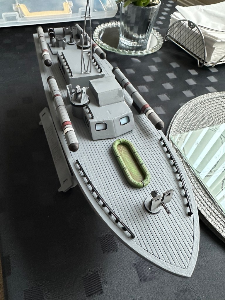
All decals placedVarnished
All decals applied and final varnish completed. I can now look at getting the rudder and electronics installed. I’m happy with how the whole hull area looks.
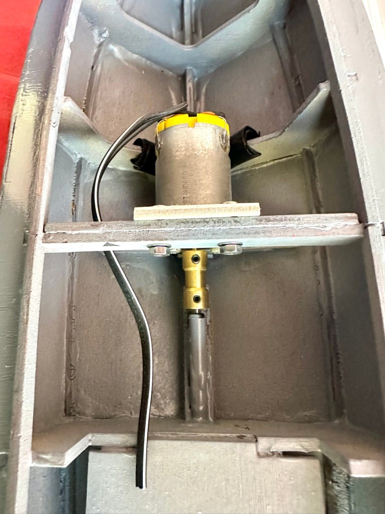
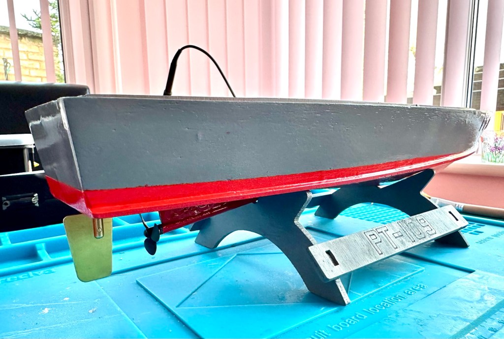
Motor, prop shaft and rudder now in placeLooking good on her stand with prop and rudder in place
All that is needed now is to place the battery, receiver and ESC in place. I have quite a strict time on this build and I must have it ready for “Lake” trials when we go to Norfolk in June.
I will also be borrowing my brother in laws pond for 30 mins or so to do a balance and water tightness test.
Let’s get the electrics installed.
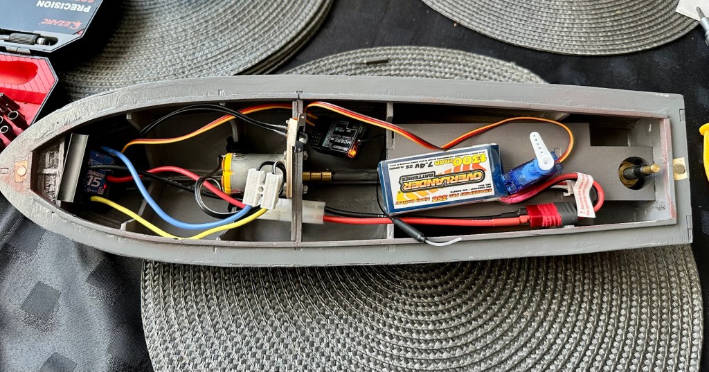
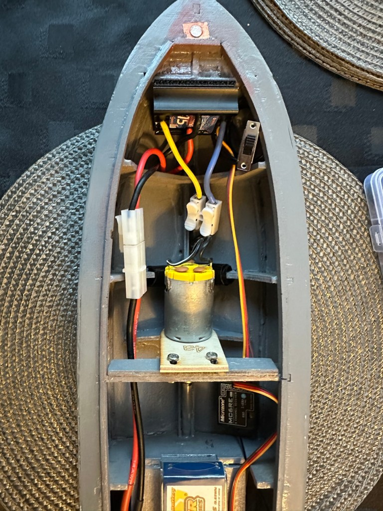
Having never really done this before, I’m quite amazed by the amount of gear I have to fit into such a small area.
All this has to go in there….i need a bigger boat
It’s in – just needs sorting
I’ve managed to put these items in-situ, in a rough position inside the hull. I need to shorten some cables, I need to somehow position the rudder servo, but I’m sure that will not be an issue. I’ve already tested the centre of balance and I’m happy with that. Later today I shall start to really tidy the layout by working from the front to the rear of the hull.
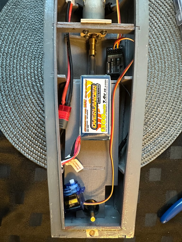
Front RearThank the Lord for Velcro tape. All complete apart from the rudder connection. I’m still working on that.
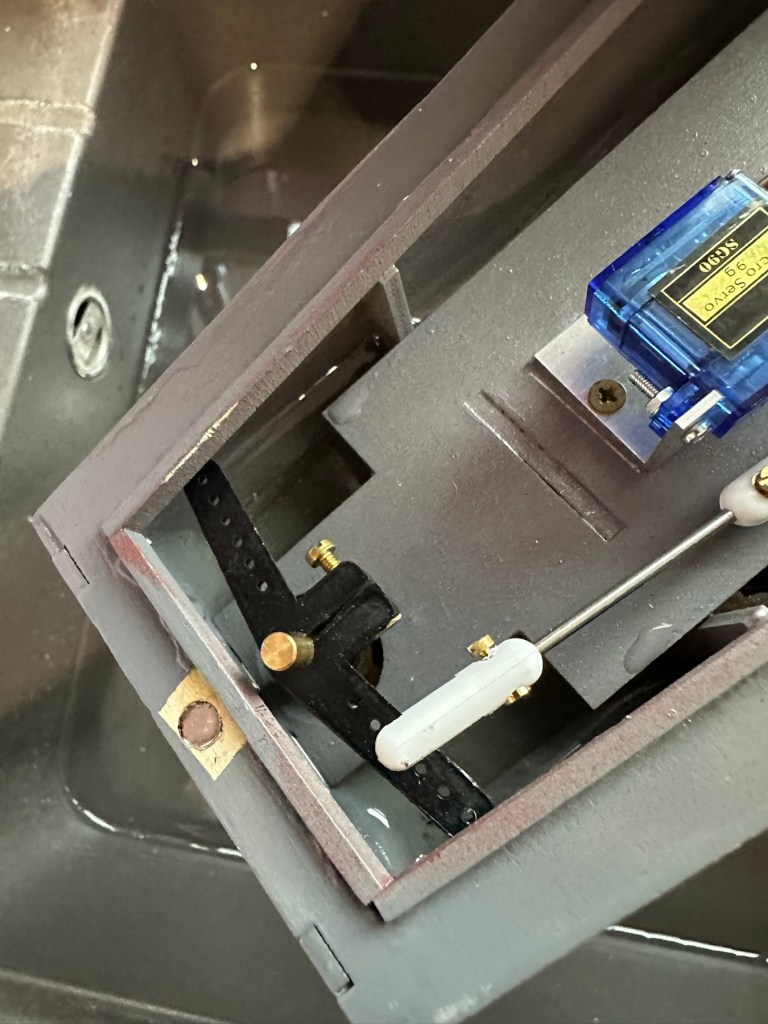
I’ve had to purchase a small bracket for the rudder servo along with a couple of connecting rods. Hopefully we can now complete the electrical connections within the hull and get the rudder operational, then I can get it water tested to check for leaks and balance.
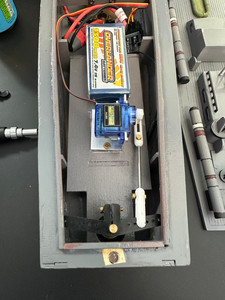
Rudder linkage in place, just needs shortening
Rudder linkage now adjusted and in place
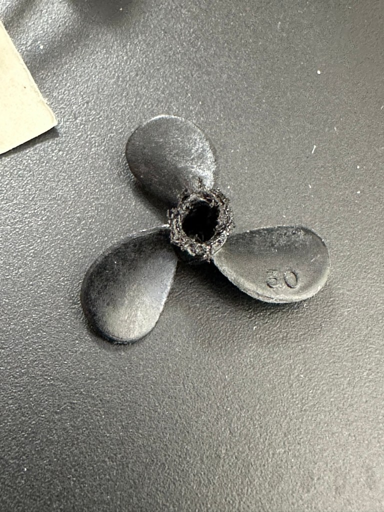
I’ve just had quite an annoying and inconvenient moment. The rudder linkage is all now in place and working fine, however the issue lies with the propeller shaft. I’ve rather foolishly connected it all up but left the propellor flush with the shaft end so when I put on full power to test, there was a burning smell as the propeller wizzed past my ear across the room and the shaft seized up. There was such a build up of friction between the propellor and shaft that the propeller melted and bent the 2mm prop shaft out of place. A stupid mistake, caused by my rushing to get this completed.
A melted propeller with the screw mechanism missing
A small video that shows the rudder mechanism working
I’ve now had to order a new prop shaft and propeller, hopefully these will arrive in the next few days and I can then get the build finished.
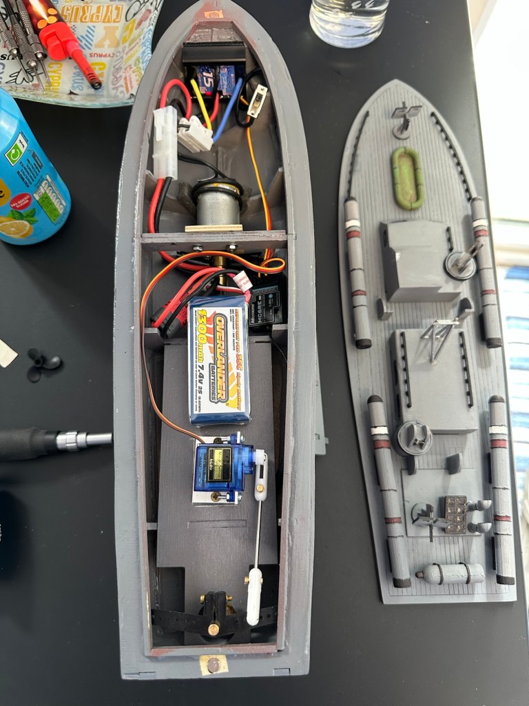
New prop shaft in place, and all electrics and functions are now operational with the motor purring away nicely. I’ve adjusted the distance from the prop to the shaft to reduce Friction and this appears to be working fine.
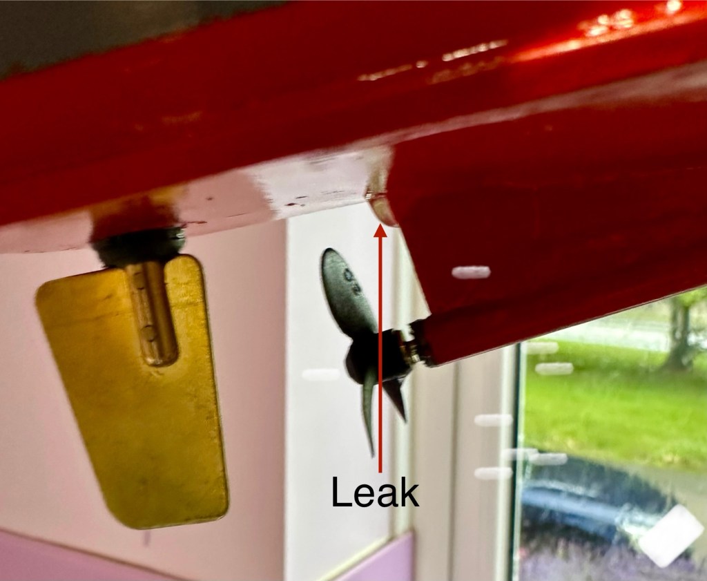
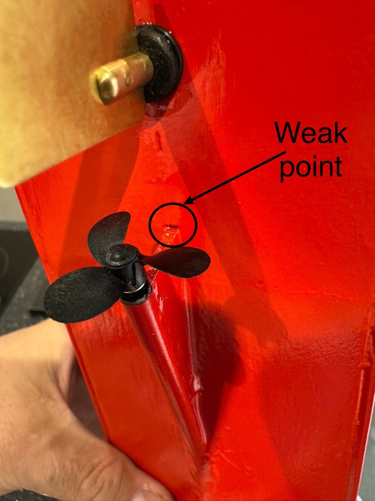
All functions working nicelyLeak can be seenWeak point found
Now to sit her in some water for leak test.
Floating nicely After 30 minutes we have water ingress
The leak test was going so well, all functions worked well and she was sitting nicely in the water.
Water test
The positive here, is that there is no leak in the front end there was no water present here. All the water was in the rear, however it was not entering via the rudder mechanism or the drive shaft.
I removed the hull from the water, tilted it in such a way for the water to gather at the rear, and dried the underside of the hull. After a few seconds you could see a drip starting to gather at the top of the mount that holds the drive shaft in place. I knew it must have been a slow leak as this took almost 30 minutes to build up, I’ve caught it just before it impeded on any of the electronics.
I’ve now emptied the hull of remaining water, it’s now drying off naturally and I have a plan in place to repair the issue once the hull has fully dried. I’m probably going to use some epoxy resin to seal around the whole drive shaft fin, and then I’ll paint and seal this part again. We will then repeat the trial.
Back in the water the following morning at 07:50 after being sealed with epoxy resin on the hull, let’s leave her alone bobbing around for 30 minutes to see what occurs. It’s not good news….again.
Timelapse over 15 minutes
As I’m impatient, I set up my camera in time lapse mode to see if I could pinpoint where the water was accessing. My suspicions were that the water was coming up the drive shaft however I’m quite pleased that the timelapse shows this is not the case. the water appears to be accessing again from the very base of the hull. This area was sanded to quite a thin tolerance so i suspect, that even with all the sealing, two coats of paint and a coat of varnish there must be tiny holes along the hull. The previous sealing I did cured the issue at the rear, it now appears that I will have to carry on with the resin coating or something similar, along the length of the hull. To make things entirely water tight I’m going to remove what I can internally and also seal inside the hull as well.
One good soaking of polyurethane varnish later…
Three days after all this varnish has dried, I have done another float test and this one was with all equipment on board for an hour…and it was successful. We seem to be dry. I’m now putting the whole boat back together now ready for its maiden voyage at Gorleston boating lake in a weeks time.
Ready to go…
I will do a separate post regarding the maiden voyage and its outcome whether positive or negative shortly after.
Thanks for passing by, as always it’s very much appreciated.
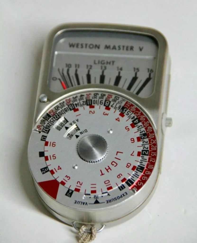
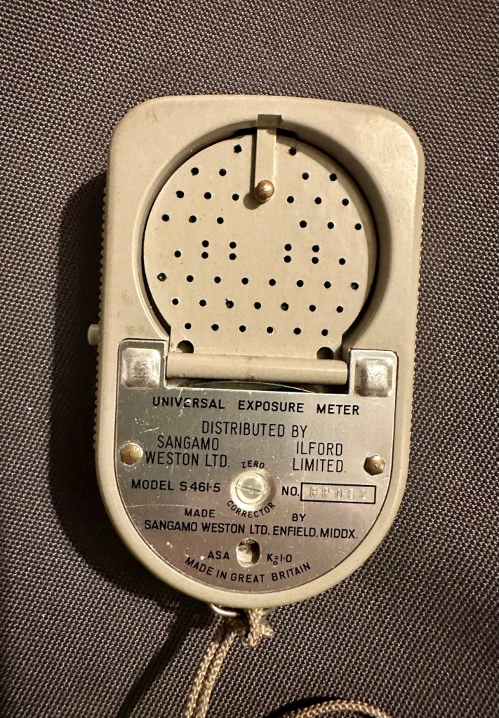
Sangamo Weston Master V Exposure Light Meter includes Invercone & Cases The exposure meter is not working The invercone will also fit the Weston IV
EBay
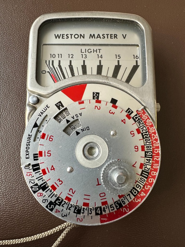
Weston V light meter and Invercone
I have brought a little item from my past history here, going way back to the days when you had to work out the light levels in photography for yourself. The exact date of this unit is unknown, however it was manufactured between 1963 and 1972. That’s two years prior to my birth and up to the age of when i was 7 years old. And I was using them when I went into photographic work approximately ten years later. These units were made to last and did their job well, hence their longevity. I’ve paid the total cost of £8:40GBP and that includes postage. I’m surprised to be honest as not only is it the light meter, but also an Invercone (I’ll explain later) and two cases. An absolute bargain in my eyes as the Invercone itself, in a case can sell for more than I’ve paid for the entire package today. Oh, and it doesn’t work and to be totally honest I don’t think I will be able to get it working ever again, as the suspected component fault is one of those little things that are only dealt with by specialist craftsmen. Add to that the problem of locating a replacement piece, as they are nigh on impossible to obtain, or in layman’s terms, as rare as hens teeth.
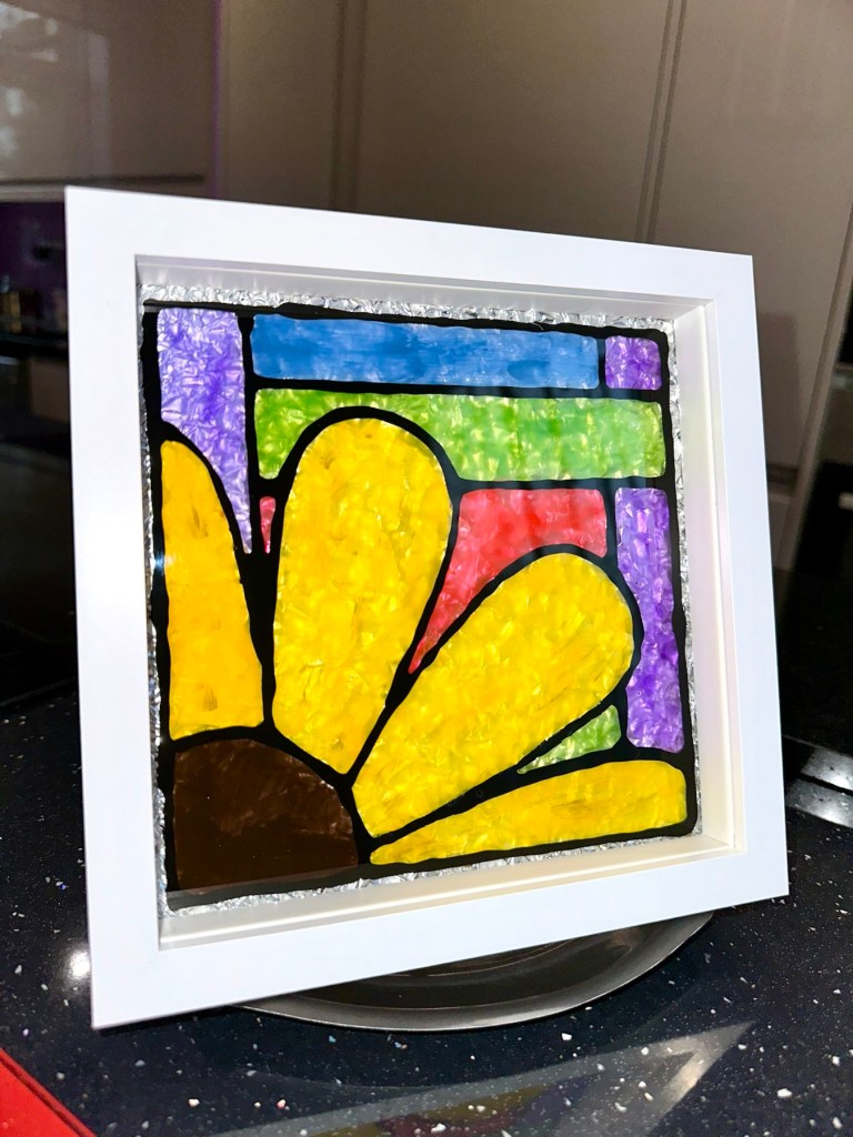
But I have read about people reviving these parts and I’m going to give that a try. If I’m unsuccessful it will be a nice piece to get mounted into one of those box frames as a historic photographic memento.
What is this part you’re referring to?
A light meters main purpose is to react to available light and direct the photographer toward making a decision regarding the settings for his camera. Things like ASA, shutter speed and f stop settings.
Therefore it needs something to sense the light. It’s not a solar panel, these were not invented back then, but it was a similar system and it was called a selenium light sensitive cell. When exposed to light, the cell generates a small electric current that deflects the needle of an ammeter coil within a strong magnetic field. The whole system is basically a Selenium cell, a resistor and the ammeter coil. The lightmeter is entirely dependent on the light sensitivity of the selenium cell for accuracy. Over many years the selenium cell ages and degrades to the point that it just stops working. It dies. Its main cause for demise is usually moisture getting into the workings and causing degradation at the contact points on the Selenium cell.
There are a number of posts/sites I have visited that claim you can revitalise these items, however I am sceptical at this. There seems to be only one person in the uk that seems to totally replace these items and that is a guy called Ian Partridge, who I believe charges around £90GBP for a repair and his site can be found Here. A fully working serviced unit can sell for up to £189:00GBP.
I’m not doing that. No way. I’m going to see if I can even get it slightly working, I’m never going to use it seriously again but I’d at least like to see the needle moving without causing any damage to its original design.
Is that the only potential issue?
No of course not. There is one other potential reason why it is not working and that is related to the ammeter coil, the axis on which the needle moves, sometimes it can become stuck, if this is the issue then happy days, the fix would be a lot easier. However this is me, and things are never that easy for me 😂
There is also a fine tuning screw on the rear that someone may have been a little bit too enthusiastic with, in the past.
And of course. The pointer lock on the side of the unit could have been simply left on. Now wouldn’t that be nice and easy?
So what’s this Invercone thing you’re going on about at the beginning?
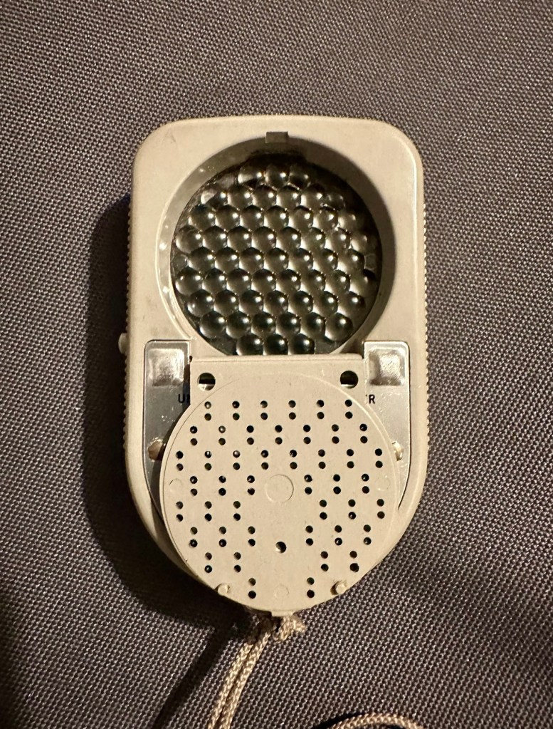
It’s that weird shaped piece of plastic with a bit of metal on it, in the pictures above.. it assists greatly in incidental lighting conditions where there is a back lit scenario.
The inverted cone shape is designed so that as the meter is angled to the light source, the readings remain accurate which they would not do if it were a dome. And because backlight effects the exposure, a small part of the invercone sticks-out beyond the top of the meter case to pick any such light up.
Sangamo Weston was a company that made light meters, among much other electrical equipment. It is particularly known for the Weston Master series of selenium meters.
The Weston Master V was produced in the UK from 1963 to 1972. It was Model S461 in the UK and Model 748 in the US
Weston was founded by chemist Edward Weston—no relation to the famous photographer—who held many patents for electrical inventions, from permanent magnets through cellulose manufacturing, dynamos, arc and filament lights and the magnetic-drag speedometer to electrical measurement instruments (and even US 895218 – a fruit box!). Weston’s son, Edward Faraday Weston, applied for a U.S. patent on the first Weston exposure meter, granted as No.2016469 in October 1935. This was a cylindrical case with an electrical meter at one end, and an iris at the other; an adjustable scale around the meter opened and closed the iris, and showed the exposure.
Sangamo was originally “Sangamo Electric Co.”, in Springfield, Illinois. It set up a British subsidiary in 1921. Sangamo acquired the Weston Electrical Instrument Co. in 1936.
Since Weston was one of the first makers of light meters, before film speeds were standardised, Weston had its own film speed scales.
At some point, Weston products were distributed by Ilford in the UK. The company was bought out by Schlumberger in 1976, but still exists, making electrical timers.
The EuroMaster light meter, very close to a Weston design, was later made by a company called Megatron.
For those who have made it this far, well done and thank you. Let’s have a look at what has arrived and assess the overall condition. It’s taken some time to arrive what with there being two recent bank holidays closely placed in proximity to each other in the calendar. Translated that means the UK comes to a halt during this period, whilst everyone gorges on poorly cooked barbecued food in bad weather whilst drinking too much alcohol.
And some of us are just working. Most annoying.
Anyway enough of the whining, here’s the assessment:
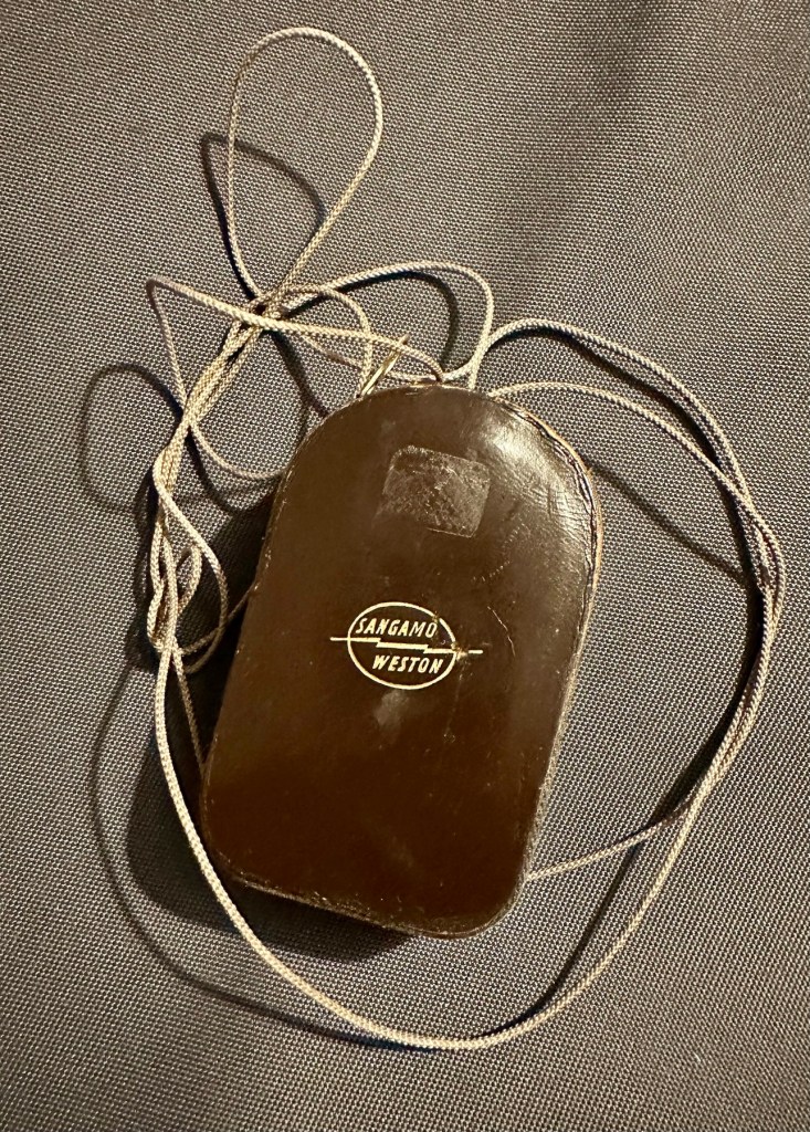
The meter has arrived and is in an excellent cosmetic condition, it came in a small leather case with a lengthy string neck strap. It’s all original and is still marked up with the original owners details on a small label. The Invercone is just what it is, a piece of shaped nylon/plastic and not much to rave on about. It is as it is, in good condition and also in a small leather case.
Original caseExcellent cosmetic condition
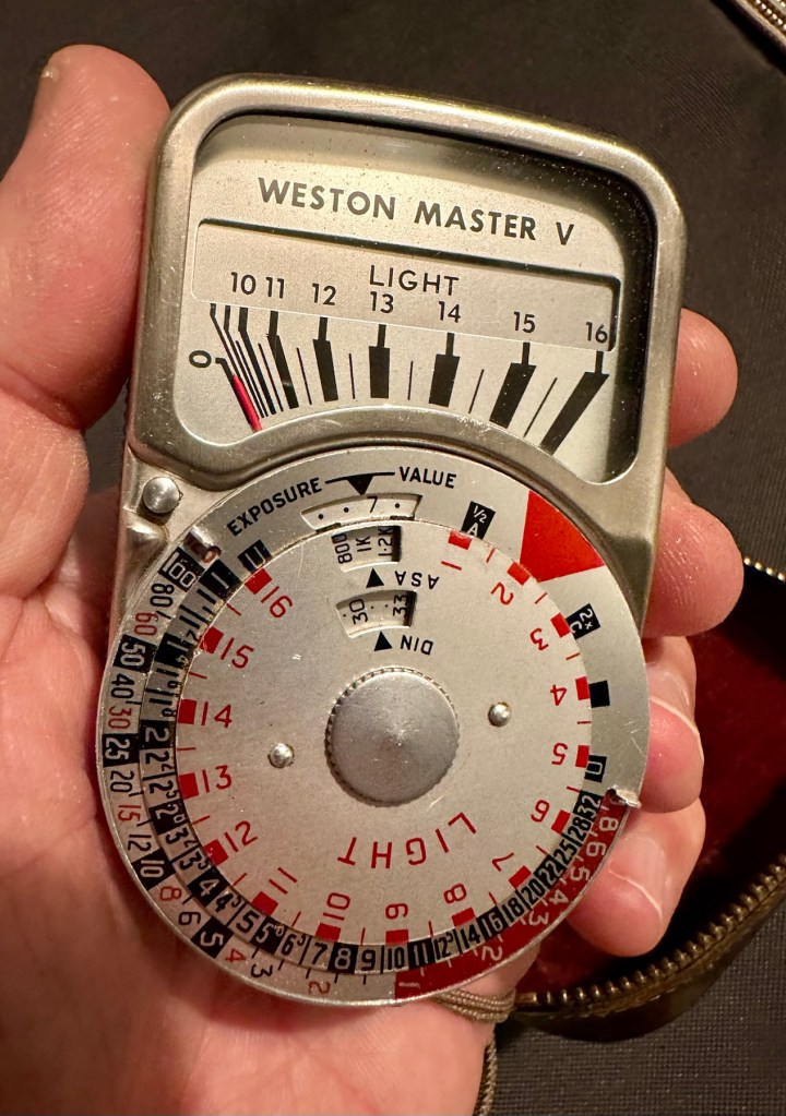
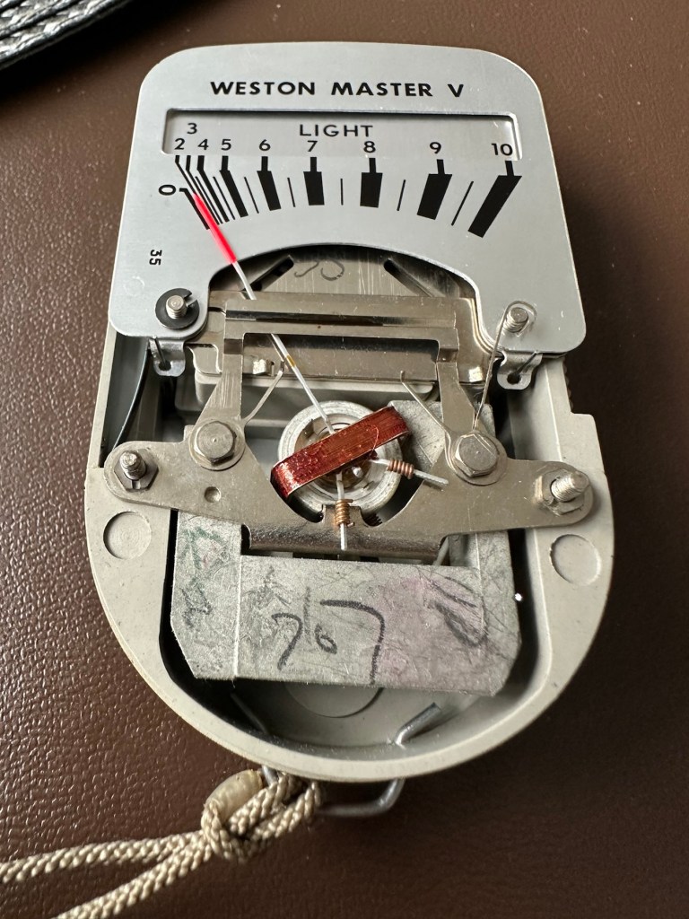
The calculator panel on the front is undamaged and in full working order, the light baffle on the rear is also operating as it should and the info panel under the viewing glass changes as the baffle is operated. The pointer lock is operating as is the fine tuning screw on the rear.
Baffle closedBaffle open
There is a very slight movement when exposed to intense sunlight with the baffle open or closed however it is only very slight. It struggles to move past the zero indicator on the scale, hence as described it is safe to say that it is not operating as it should. We will have to look inside to see if there are any obvious issues, however I strongly suspect it is related to the Selenium cell. I would like to see if we can get this operating, I’m not overly worried about its accuracy as I’d just like to see it move through its entire range. It would be good to see if it is at all possible to revive a “dead” light meter. We can only learn from dismantling and investigating such items.
Repair:
I’ve left the unit in sunlight for a few days, as this has been known in some rare cases to just kick start it back into life. That doesn’t seem to have worked in this case so let’s have a look inside.
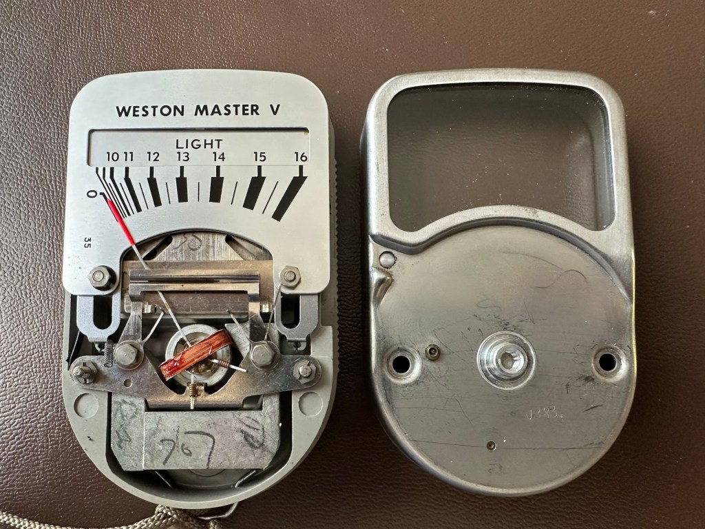
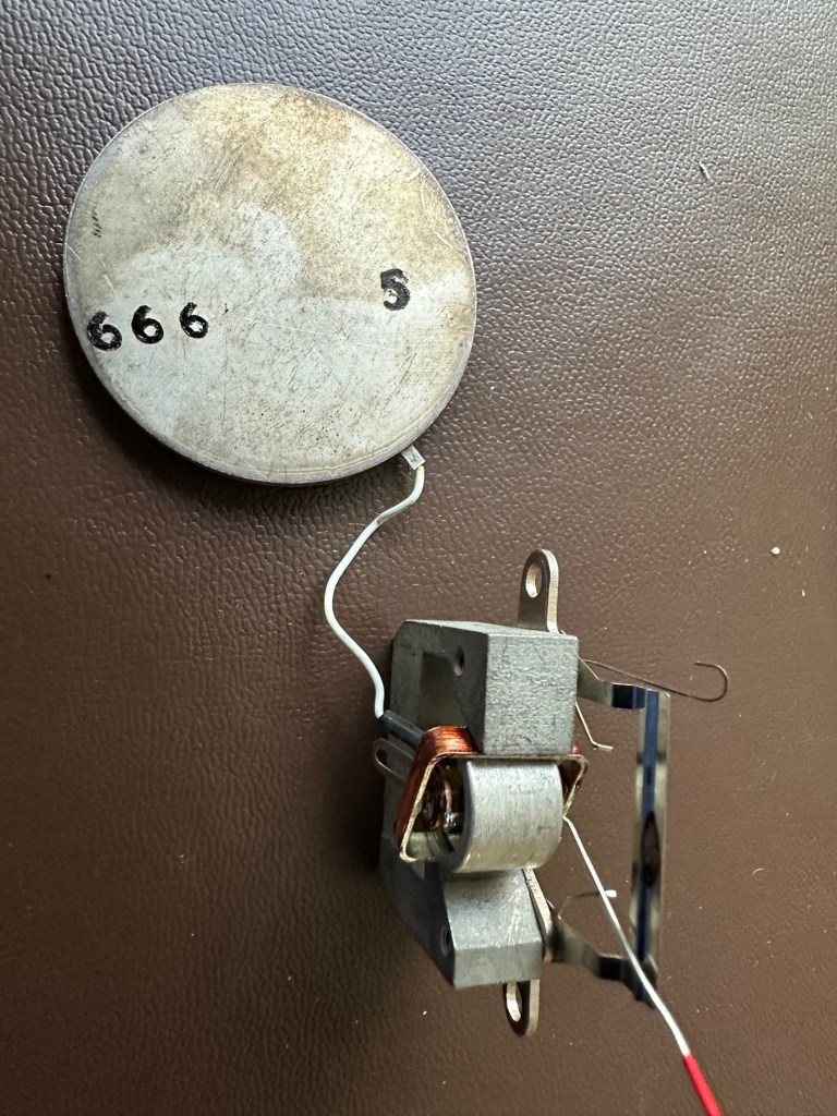
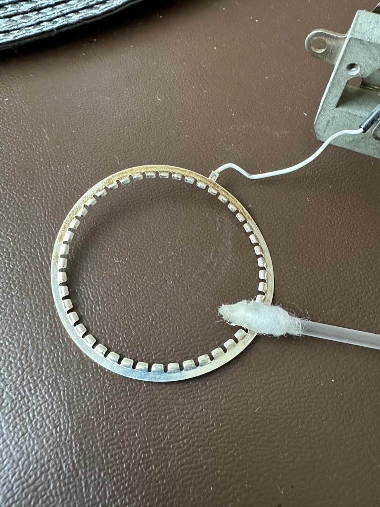
Remove securing thumb screwRemove two nuts Case lid lifts offCarefully remove fascia platesRemove sliding needle lift mechanism and expose selenium cellCell, armature ring and ammeter coil removedCell connecting ring cleanedCell contact ring, cleaned and renewed
The whole unit came apart quite easily to expose the selenium cell deep in its workings. Using a multimeter on the cell, indicated life in the item as values changed as the cell was moved from the dark into the light and vice versa so I am confident there is some life still present in this cell, but is it sufficient to power the meter? I have then used the lowest Ohms setting available and put the negative lead on the magnetic case (Ground) of the ammeter coil and the positive lead on the wire connected to it and there is no movement at all. This indicates to me that the ammeter coil is at fault and unresponsive to any voltage, I believe this is the problem and at this point the repair is not possible. I have cleaned the cell connecting ring to the point that it is now shining and free of any age related contamination. The contact ring on the cell itself I have revitalised with a metallic silver pen. I have checked continuity and that is also good and acceptable. One thing I did not see in this model was the use of a resistor that is used in most selenium cell light meters between the cell and the ammeter coil, maybe there was never one used within this range of meters, I’ll have to check that out. I have checked this out via numerous sources and it appears the Weston light meters never had a resistor placed in line at any point, so that has cleared that question up. This unit is dead due to a faulty ammeter coil.
Result:
The unit is cosmetically very good and I believe the actual selenium cell is functioning but at an exceptionally low level. The tests on the meter ammeter coil have come back negative indicating that there is no life in this part of the meter. I suspect the fine wires on the coil are possibly damaged. The only way I can get a working unit would probably be to obtain another faulty unit to transplant parts, I may well do that in a later post.
I hate not getting the fix done, however this unit is in excess of 50 years old and to be honest the odds were stacked against me from the start. I did state that I may actually mount this item in a frame as a photographic art piece, that may still happen but I’d love to prove the original cell is still functional if I can. Maybe I just might buy a donor unit to test my theory on.
I’ve learned a lot from this post on the repair and dismantling of these units so that is a big positive. Knowledge is always king as they say.
It will not go to landfill. It will be reused in some form, you may even yet see a follow up post regarding it.
Thanks for passing by, it is always very much appreciated.
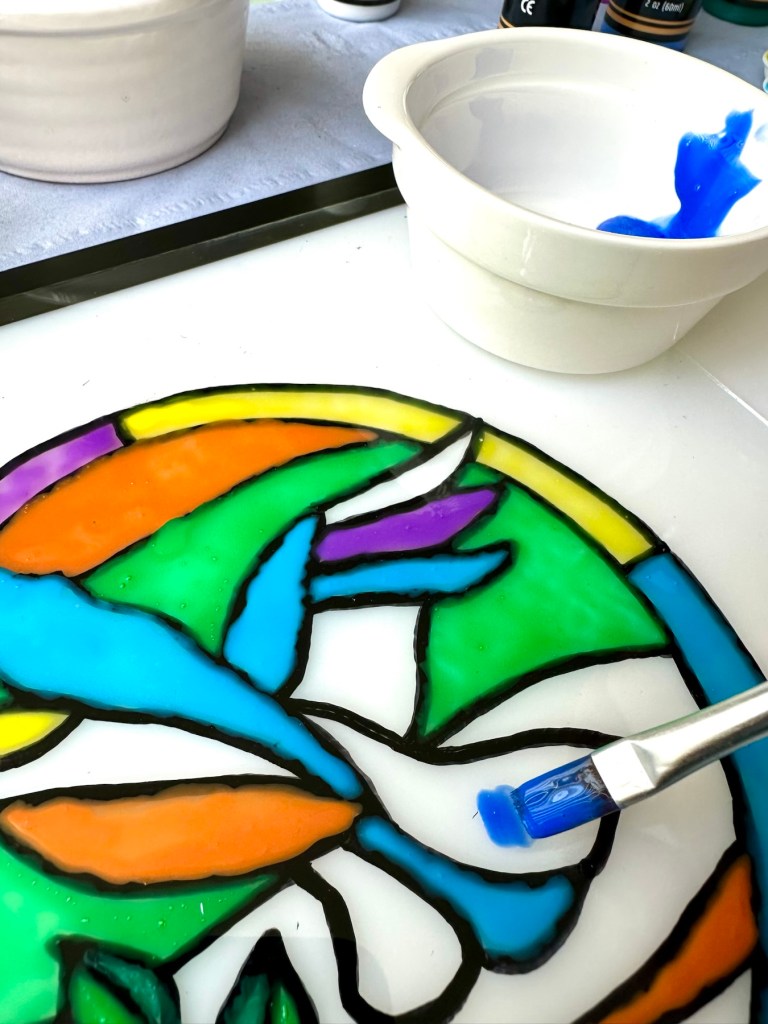
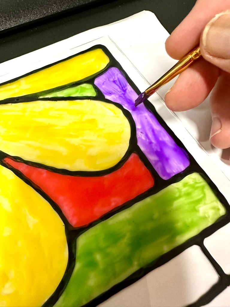
In my first foray into this art medium, i chose what were to be two of my first templates. That post can be found here: Faux stained glass painting. This post covers what I will be doing with the second template and a slightly different approach to what I hope to achieve.
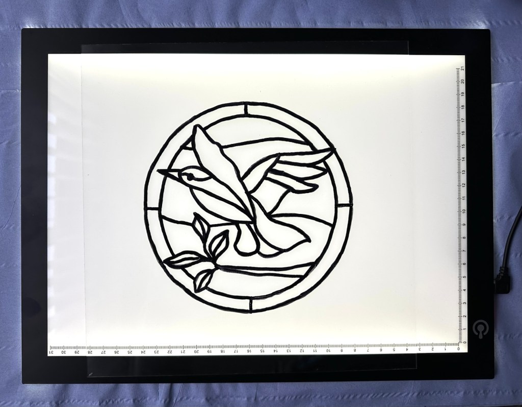
I have already traced an outline onto my glass and this time instead of using paint and glue for the lead effect I have used a Pentel permanent marker. I will do the painting on the opposite side of the outline as this will allow me to make amendments to either the outline or the paint without interfering with each other. Because the paint is mixed with glue this can easily be peeled off and re painted. The outline can be amended by using a cotton bud and some IPA. Making changes with the outline and the paint on the same side would require cleaning the whole glass and starting again from scratch. I want to avoid that, so that’s why I’m experimenting.
My second template, drawn with permanent marker
I’ve brought some new Acrylic paints, and will be using slightly more glue in the mix to try and achieve a slightly more translucent effect, to assist with the effect I’m trying to achieve.
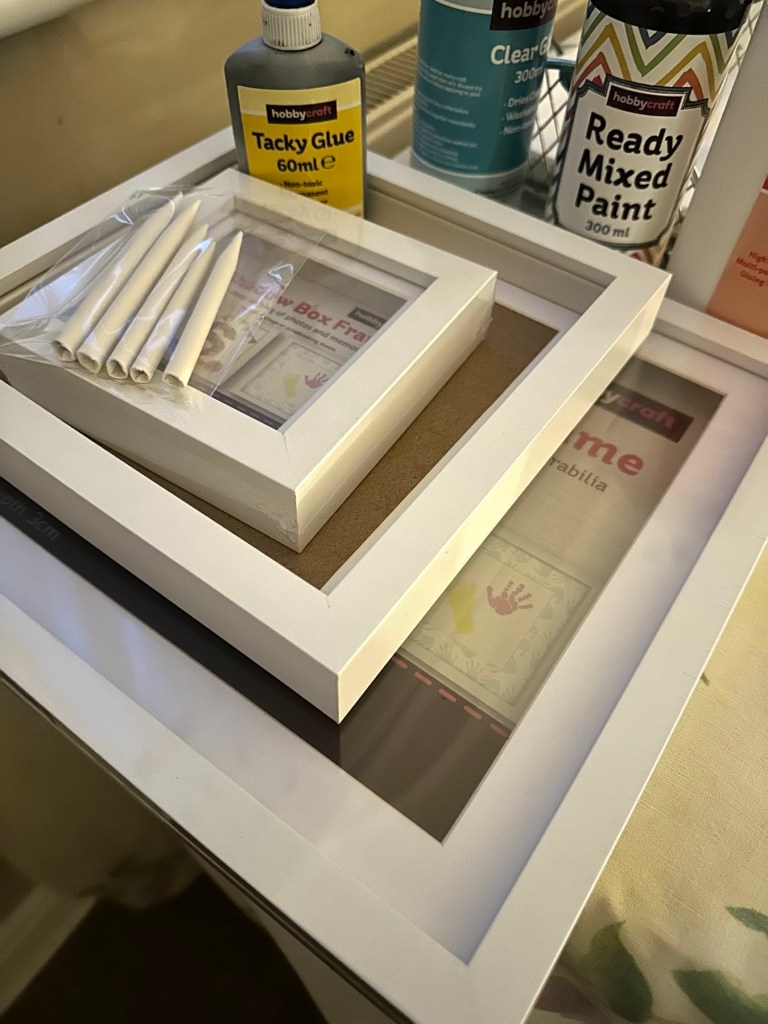
As you can see I will be using a box frame for this piece. What I want to do in this example is to put some lights in the frame, but to ensure the light is not too harsh I want to put some opaque tissue immediately behind the glass to act as a diffuser. I’ll get around to this later in this post.
Let’s get painting.
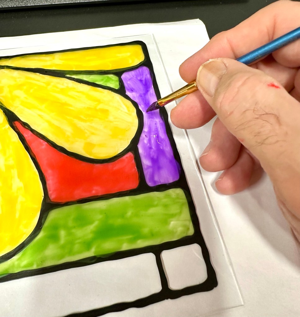
Today i’m using a small light box under the glass so i can get a good idea of how the paint is going down. It also saves me from constantly having to lift the glass to the light to see how it is looking. The glass is very thin and the less it is handled the better.
My light box
Time to paint
Time to dry
When dry I just flip the glass over and go over the out lines once again, this time I’m going to add a small sting of lights into the box for display at night.
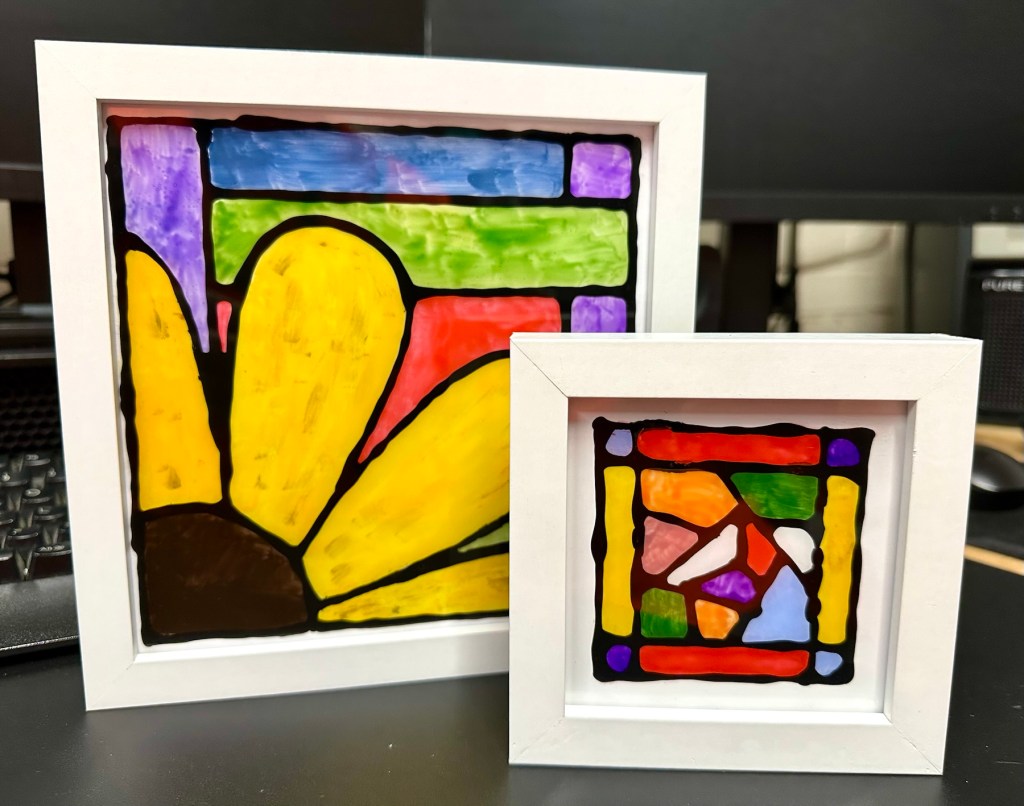
Mounted in a box frame. I have hot glued some lights into the inside of the frame
Box frame Better at night
I’m a tad unsure about the lights but I’ll have to wait until it’s dark before I make my mind up about this one. Been fun, I’ve enjoyed it but I’m sitting on the fence regarding the lights, but you never know what’s liable to happen unless you give it a try. I may try the foil trick on this one as I think it may be more effective.
My original three frames i purchased, to use as templates for this particular Art medium
I’m new to this art medium, I don’t really know what I’m doing, but like everything I do on this site, I’m willing to give it a go, always willing to learn. So here we go.
I was watching a program on TV a week or so back and was watching a stained glass window being repaired. I was fascinated with the expertise and commitment these guys put into repairing these pieces of art. I thought to myself that this is something I would love to try but obviously I just don’t have the expertise, space or ability these guys have.
So I had a look around for simpler alternatives and that’s where I found out about Faux stained glass painting. It’s a whole lot easier, less expensive, and I have most of the tools required already.
I’ve attached a video of the technique that I’m interested in, this video has kind of sold the process to me.
I’m going to give this a go now, let’s get started.
My Subject:
I’ve chosen two simple potential templates that were free to download from the internet. As this is my first attempt I’ve chosen a couple of design templates that will be good for a first attempt at this type of art. I’ve chosen a bird and a simple flower.
The two templates I will be choosing from for my first attempt at this medium
What do I need?
Not a lot to be honest, below is the minimal requirements.
Craft PVA glue
Craft clear glue
Paints – I use acrylic, you can use pretty much whatever paint you have around.
An old cheap frame, with glass
Brushes, or sponge applicators, some tape and cleaning materials
And that’s basically all you need.
Ive been out and purchased some supplies including some shadow box frames that were on offer. These will be my guinea pigs for the purpose of this post.
Supplies
I’ve chosen the flower template for my first attempt as it is slightly less involved. I’ve mixed some black acrylic paint in with some PVA as this is what you use to form the black “Lead” type outline. I’ve done some samples on plain A4 paper to perfect the technique as it was coming out all blobby and runny, I think I’ve now perfected how much the nozzle needs opening and now I’m quite happy with the outcome.
Let’s go:
Next i tape the template to the rear of the frames glass, i then clean the front of the glass getting rid of finger prints and anything greasy that might stop the ink bonding to the glass.
Paint/glue applied a bit blobby
Using a steady hand you then just add the glue/paint to the top of the glass following the template underneath. Don’t worry too much if you get some blobs and bubbles, the bubbles can be burst by using a needle and the blobs can be dealt with when the solution dries, because the glue can be easily cut or peeled back. Don’t worry too much about little mistakes, just go with it. Don’t worry about making straight lines perfect as the irregularities just add to the authenticity of the piece. You don’t see perfect lines on old stained glass windows, so don’t worry. I use some small paper tortillons just to remove some small smudges and they work fine.
Glue and black paint mixUsing a Tortillon to clean it up a little
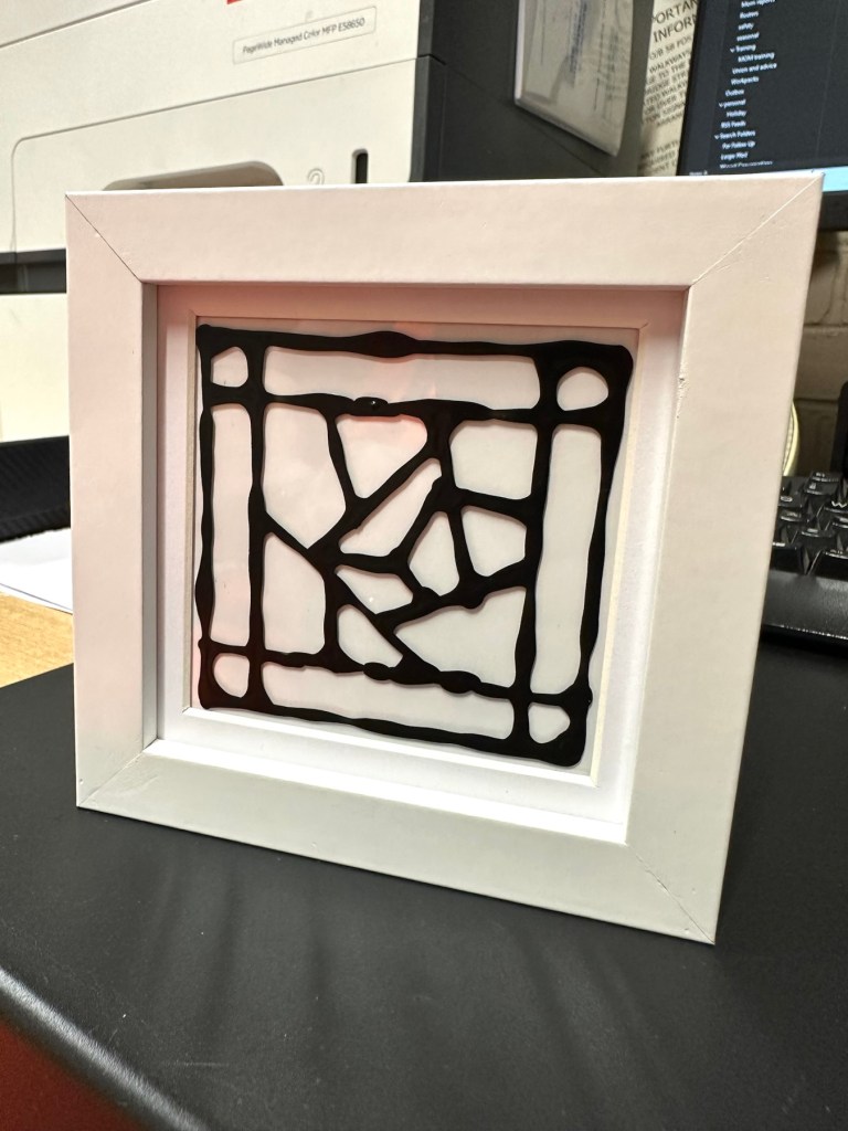
Now we just need to wait for the outline to dry and I’d suggest leaving this for a good eight hours or so.
Whilst I’m waiting for this one to dry I’ve done another small one with just some random geometric shapes. I love the way this one has just spread out and gained a great scruffy edged look. Can’t wait to paint it.
Just the glass, and dried outlinePlaced in its frame to see how it might look.Second trial piece ready to paint
There are many ways to do this technique and the video at the top of the page gives yet another two ways to obtain this outcome. These are my first two attempts and I’m going to try the techniques in Emily Seilhamers videos at a later date. Meanwhile back to my two attempts.
For painting you need some clear school glue and whatever your preferred paints are. I’m using some acrylic paints as I have plenty of them around. Using a tiny spot of paint you then add some glue at a slightly greater ratio than the paint, the thinner it goes on the more translucent it will be, if thicker it will be more opaque. Don’t t worry about paint strokes, it will happen as you are painting with glue. The good thing is if you are not happy with the outcome you a can always use a craft knife and just peel the offending colour off. It’s easy.
Here I’m painting, probably a little to thickly, and I’d probably be better with some glass or enamel paint. Lesson learned.
The good thing is that this paint dries really quick and in a warm room it’s probably dry in just over one hour.
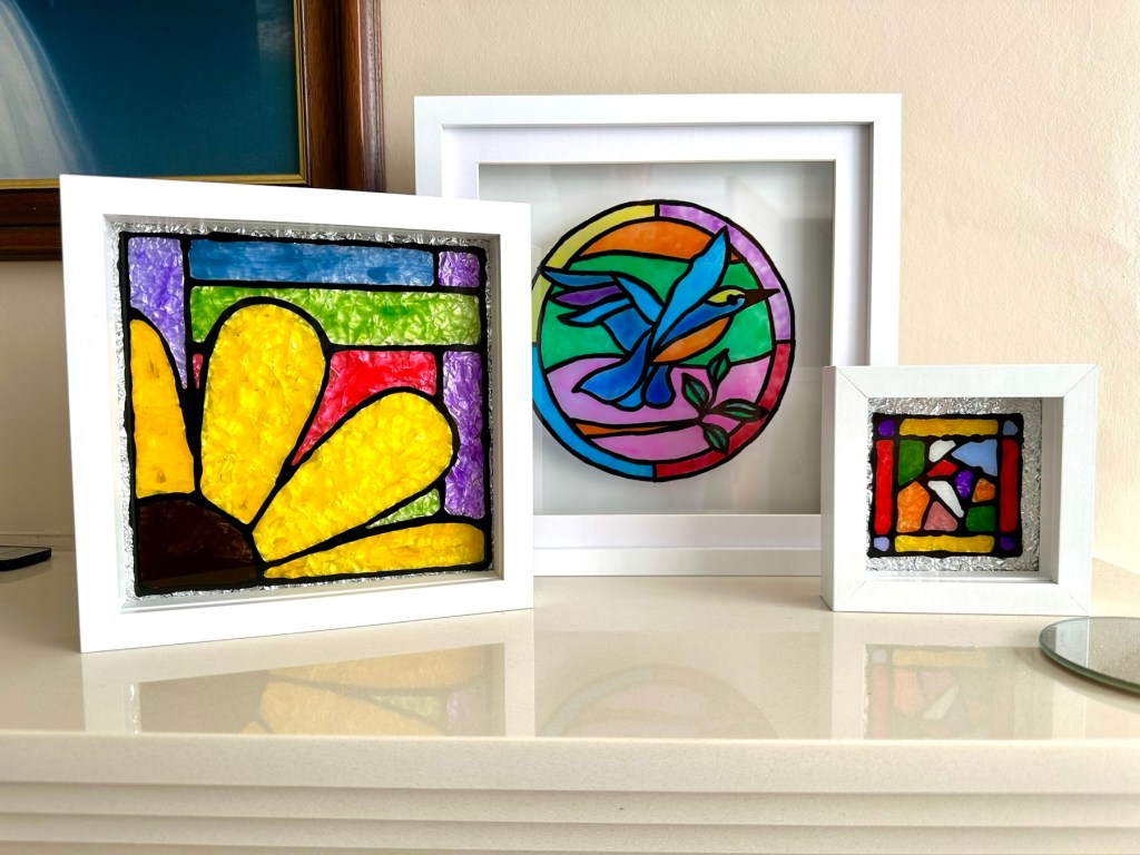
I’ve placed my two attempts in box frames. I’ve got one final thing I want to do before they are finished.
I’m quite happy with my first attempts, there are little mistakes and many things I have learned from trying this medium. I’m not going to make any changes to what I have done as I want to display them as battle scars. You know, a snapshot of what I did at the time and how I have learned from it. The next examples will be better, I have a third one of these box frames and that will incorporate all I have learned from doing these little prints. It will be just like a journey into Faux stained glass in three parts, and they will all be on display.
This project isn’t quite finished yet though, there is one other thing to do. The perfect place to display these items of course is right up against a window just the bare glass, allowing the sun to come through and show off all those lovely colours. However you can also display these pictures within frames and this finishing touch courtesy of Emily Seilhamer, completes that look.
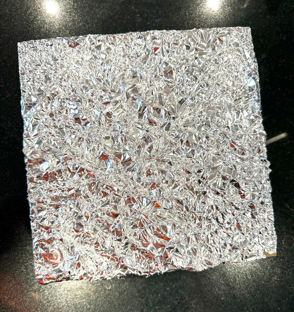
You just need some kitchen foil. Yes you heard correctly. Kitchen foil.
Cut a piece of foil just slightly bigger than the backing cover of your frame. Now scrunch it all up but not too tightly. Just move it around in your hands until it appears to have an even amount of creasing as this is to be come your light refracting layer.
Scrunched up tin foil
Attach this to the frame back and then secure it back in the frame against the glass you have painted, trim and tidy the foil using tape at the rear of the frame.
Now turn it over
Look at the difference with the foil effect
Attempt No:1Attempt No:2
See how that tin foil now reflects all the available light and makes your picture look totally different. The refraction appears to help cover up the brush strokes we discussed earlier, and you can now display your pictures in any area of the house, and any available light will be reflected on to and will enhance your pictures.
On the fire place
I hope you have enjoyed this post, as much as I have putting it together. Thanks as always for passing by. It’s always very much appreciated.
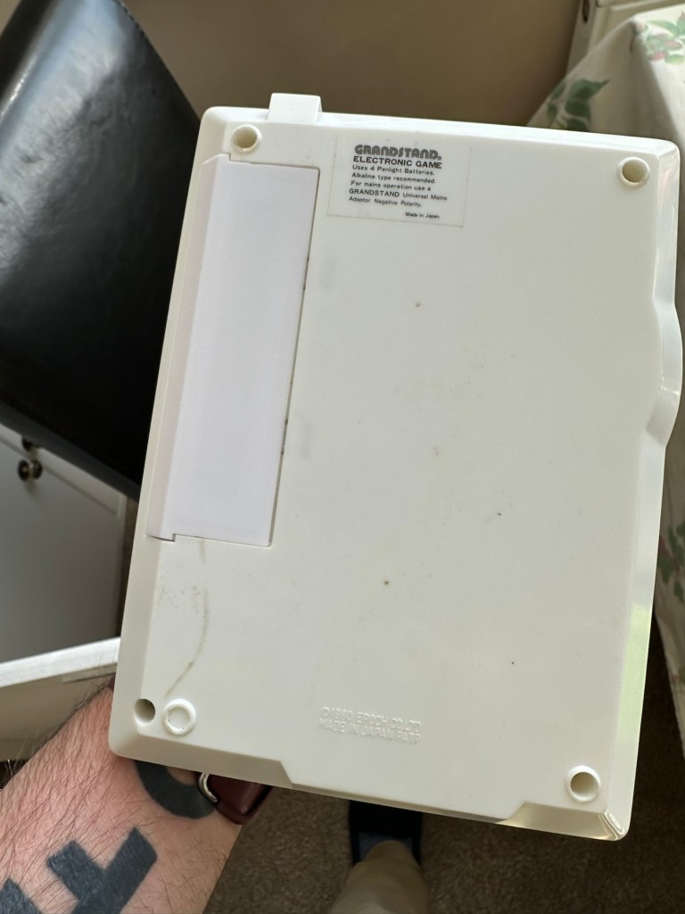
Can’t get to turn on unfortunately. No battery cover. Any questions please ask
EBay
Dirty unit No battery cover
I know, there is no battery cover, however I have already sourced a seller of one if needed. This item looks quite dirty so a good soak might be the order of the day to get started. I’ll wait for its arrival before I jump to order any other bits for it.
Now as I’ve said in the past these units fall into that crazy price category on the selling platforms as the “New Antiques” of today. For an item that was low cost, somewhere between £25-40GBP when it came on the market, they can certainly command a wide range of crazy prices, here is an example of price ranges from today:
The massive range in prices for these units
This one I purchased today only came up for sale about 3 hrs ago and I thought it would have been snapped up by now, it hadn’t so I didn’t hang around any longer and purchased it for a total of £16:38GBP including its delivery. I’m not going to get too smug yet, as for all I know I may have just purchased an empty shell. Let’s wait until it arrives.
Here’s a little history of this unit:
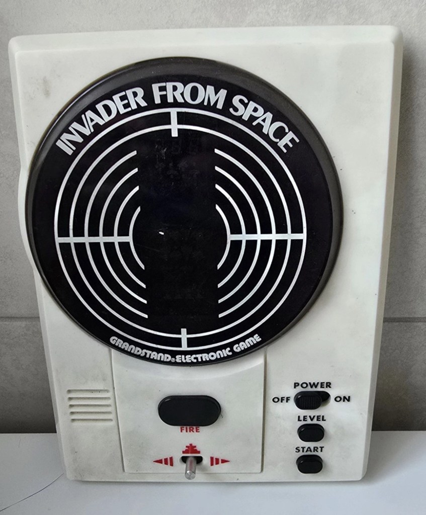
Grandstand “Invader from Space” is a tabletop LED game dating back 45 years to 1980. Four ‘AA’ batteries power the unit or, alternatively, the Grandstand 5.5V@300mA power adapter (or an equivalent power pack) sold separately. The game, licensed to Grandstand, is a copy of Epoch’s “Invader from Space”
The company initially behind the “Grandstand” label was Adam Imports Ltd., (from 1980 Adam Leisure Group Ltd. and by 1983 Adam Leisure Group PLC) founded in 1973 by Chris Rycroft and Les Kenyon of Harrogate, UK. The company initially started as a mail order company and was the single largest supplier of calculators in the UK by 1974. By August 1978, George Bassett had acquired a 75% holding in the capital of Adam Imports for £750,000 cash, plus 60p in the pound of profits before tax in excess of £500,000 for year to December 31, 1978. Adam Imports was re-acquired from George Bassett by Chris Rycroft in 1980. It chiefly imported electronic products from other manufacturers such as VTech, Epoch, Tomy & Entex, selling them in the UK re-branded under the Grandstand name.
Wikipedia and others
So that’s the history
There is a good link to a similar repair on YouTube from a guy I follow named Stez Stix Fix, it’s very much worth a look and he has a great if not sometimes crazy way of diagnosing and repairing items. A cool guy though.
The Grandstand invaders from space game
Anyway back to my own purchase.
Assessment:
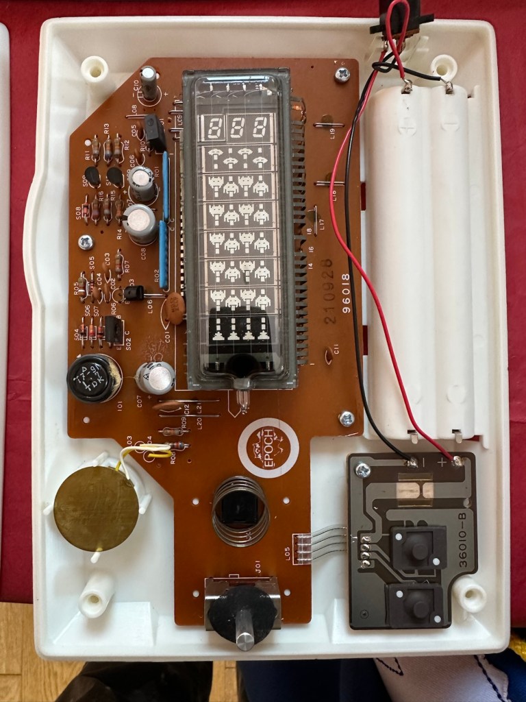
I must admit the unit doesn’t look as dirty as in the original pictures. The battery cover is missing and there is a crack in the side and a deep scar at the bottom, this won’t be too much of an issue if I can weld it all back together. I will still give it a good soak to clean it all up though. I’ve put four batteries in place, and the unit is definitely dead. There are no loose wires, voltages are getting around the board according to the multimeter and nothing is getting hot. There appears to be no short circuits, and then I notice this, capacitor CO7, slight bulge on top and what looks like leakage from the bottom. We have a candidate as to why this unit is not working.
CO7 looking unhealthy to me, you can see the component to the left that looks like it’s covered in a fur ball. The result of the old capacitor “coughing”
I’ll whip this out and see what we have but I suspect this old capacitor has failed and is causing an issue, heres hoping I have a suitable replacement.
Repair:
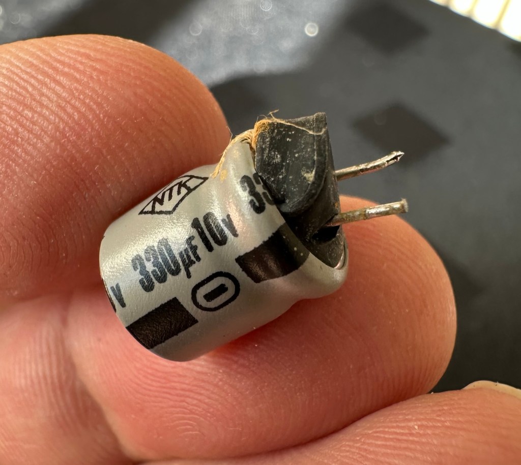
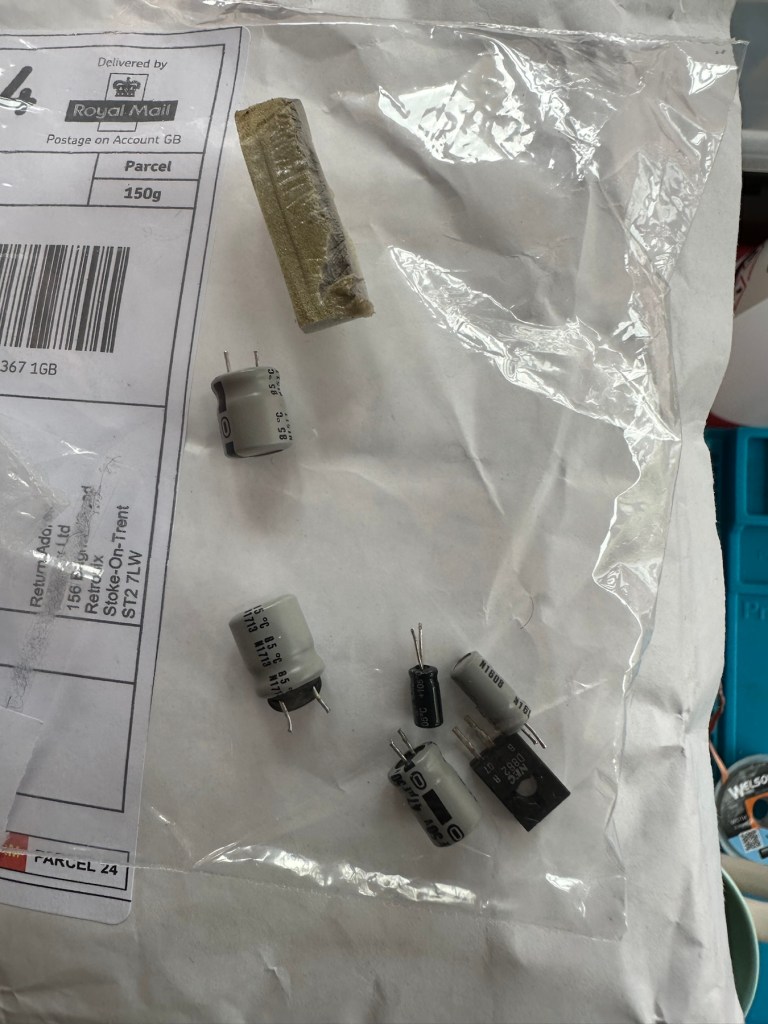
This little beast is a 330uf 10v electrolytic capacitor. I have none available so have had to purchase a pack of ten. These should be here in the next few days. There are three other old electrolytic capacitors that I will also change whilst I’m in there, as these are all likely to fail at some point soon. These components are now all around 45 years old, it’s a wise move to change them out.
One very dead capacitor removed.
I’ve ordered a 3D printed battery cover to replace the one that is missing. This should be here in a couple of weeks.
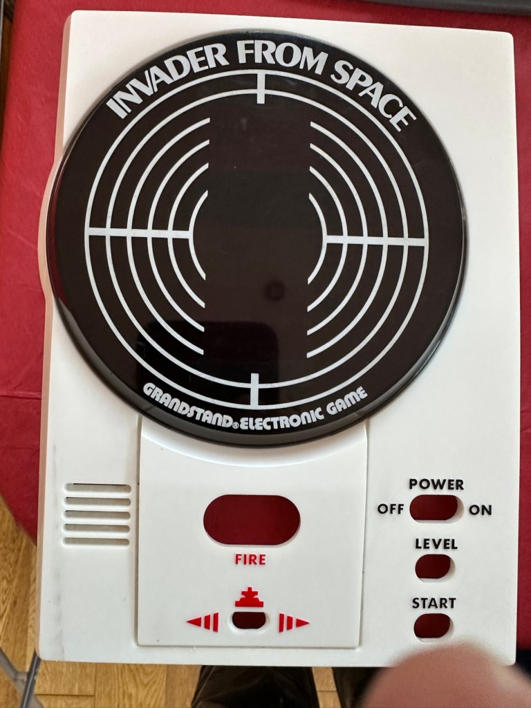
Whilst waiting I have cleaned the inside and outside of the casing as best I can. I still have a piece of broken surround to repair, however this is just a simple glue and a little bit of support job.
Case inside and out cleaned
Broken surround repaired
The surround that was broken has been repaired and secured with some nylon soaked in a superglue compound inside the casing. It’s rock solid. Outside the break is hardly noticeable. The break is secure and much stronger now.
New capacitor here
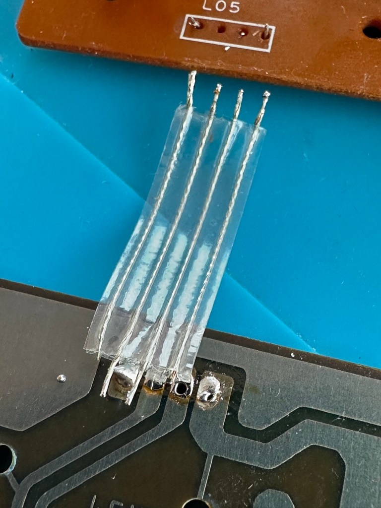
I’ve replaced all the offending capacitors and the unit remains dead. I’ve reflowed most of the board as there were some dry solder joints. I’ve also rewired the bridge from the control panel to the main board as one of the wires here had broken.
Bridge required resoldering
After using the multimeter to check some traces and components it’s now pointing to this component (a power transistor D882) being the cause of this catastrophic breakdown as its readings are all over the place. I suspect this item has overheated, the capacitor has blown and then it’s just died itself. I’m probably wrong, but I know what I mean. Probably just a catastrophic chain of events that all contributed to the units demise.
D882 transistor – power regulator
And as usual I have none available so will have to send for some new ones. The new components have arrived and the new power transistor has taken its place on the board. Now reassembled I place some new batteries in and the unit comes to life. It was the power transistor at fault, I should have really checked here first after seeing that damaged capacitor at the beginning.
All old components removed and replaced in this unit
Not to worry though as it’s had a good overhaul and has been totally recapped as a precaution. I’ve used some conformal coating on a few tracks that had some copper exposed after a good clean, to ensure they don’t deteriorate any further.
It has life
The unit is looking really good and these items were traditionally very loud and this certainly is. It’s working well just as it should do and I’m exceptionally happy with this repair. I’m still awaiting the battery cover that I have had 3D printed and this should be here in the next week to complete the fix.
No scoreHere we go3D printed cover arrived. Minor adjustments needed but in all a good purchase
So with that I will bring this build to a conclusion. It has been a fun project, I’ve learned a number of things about this circuit board and gained valuable knowledge.
But best of all we have rescued another item and saved it from landfill.
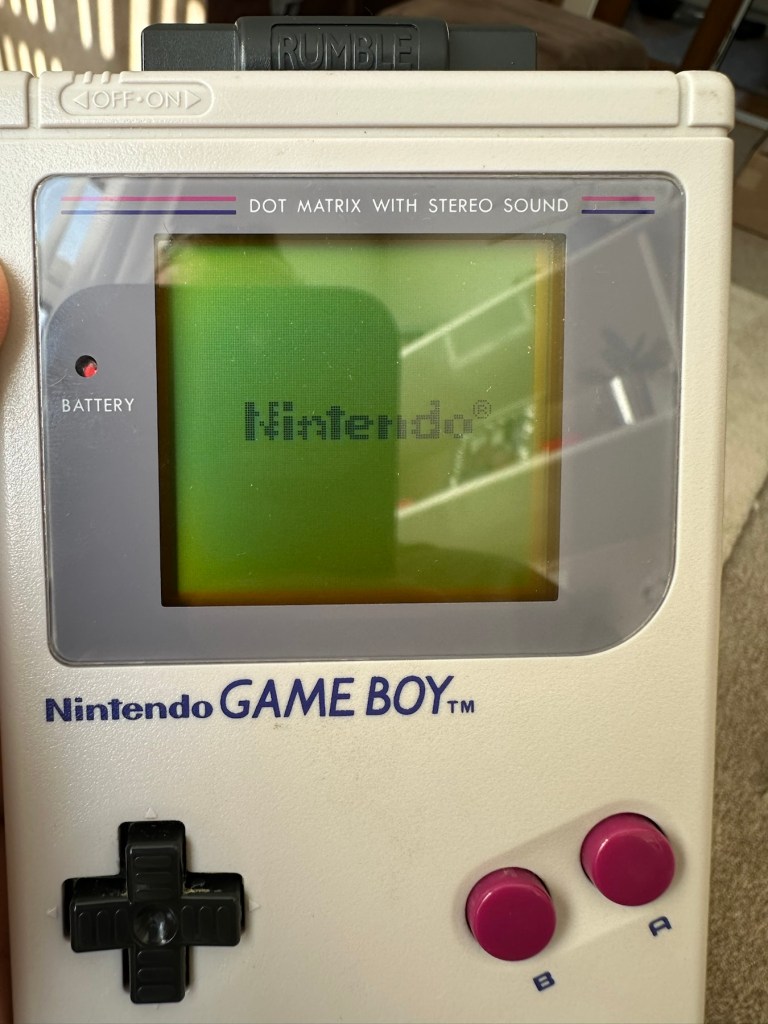
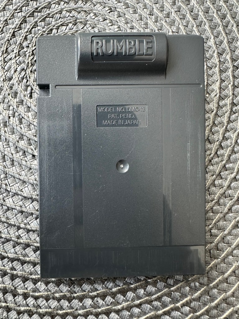
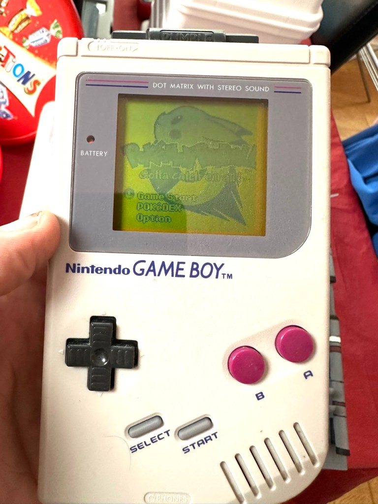
You will receive what you see in the photos, please look at the photos as this is part of my description to show you what you would be receiving. Please note the game comes up with the main Game Boy & Nintendo screen & then won’t go any further, as you can see👀in the photo.
Any questions please feel free to ask.
EBay
No getting past this pointOriginal Nintendo pinball game – Non operational
Hopefully this will be a simple repair, but who knows it might just be a little more technical.
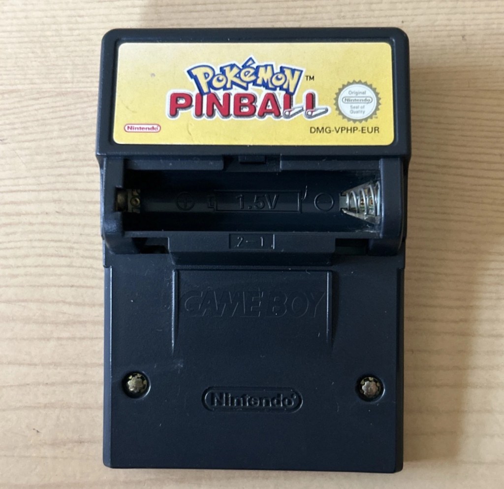
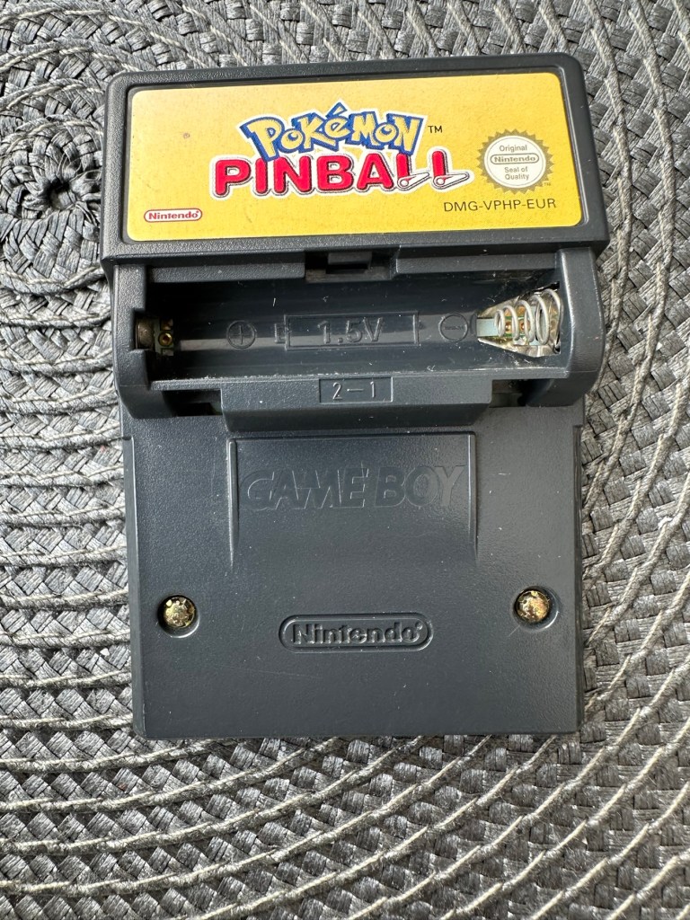
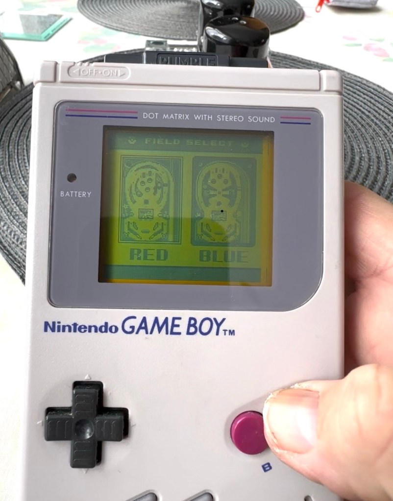
This game is built for the game boy colour console and is an original Nintendo product, it is the Pokémon pinball game. I’ve purchased something I never normally buy and usually detest buying, an item with the battery cover missing. Damn it, there is a fortune waiting to be made by anyone who owns a decent 3D printer, with the amount of missing battery covers that are waiting to be reproduced out there. Edit: ( Just looked on line and it seems the gaming community are already on the case, loads of options available, great to see) Anyway I’ve brought this unit as it can either be kept to await a suitable battery cover or passed straight on. Edit#2: I have, in anticipation of its arrival already ordered a suitable 3D replacement cover from a UK company. It was probably the best priced and best looking print to be honest, some of the others looked a little rough and postage was excessive to say the least. These guys at Cool spot gaming were the best in my opinion.
Released in Japan in 1999 this game made it to European shores in 2000.
These games came with a rumble pack at the top of the cartridge that simulates the vibrations of a normal pinball machine, and I believe this is what the single cell AAA battery is for. And as it is a black cartridge this indicates it can be used on the GameBoy colour and original versions. I have purchased this for about half the price that a good working one with battery cover sells for, now that I’ve had to pay for a 3D replacement battery cover I now move into the higher end price of the cartridge valuation, however I do have a few pounds worth of wriggle room should I decide to sell, considering most of the ones on sale at the moment are missing the battery cover and commanding horrendously high prices. I’m comfortable with that. That said it will go into my personal GameBoy collection anyway. Let’s get it working.
Here’s a link to the actual 3D print program for the battery cover on Thingiverse, if you should ever wish to print one yourself. I have absolutely no idea about 3D printing so this is just like brain surgery to me: 3D print program
Assessment
A nice tidy little package has arrived clean, battery cover missing as stated and exterior looks nice and clean. Original label is intact.
Repair:
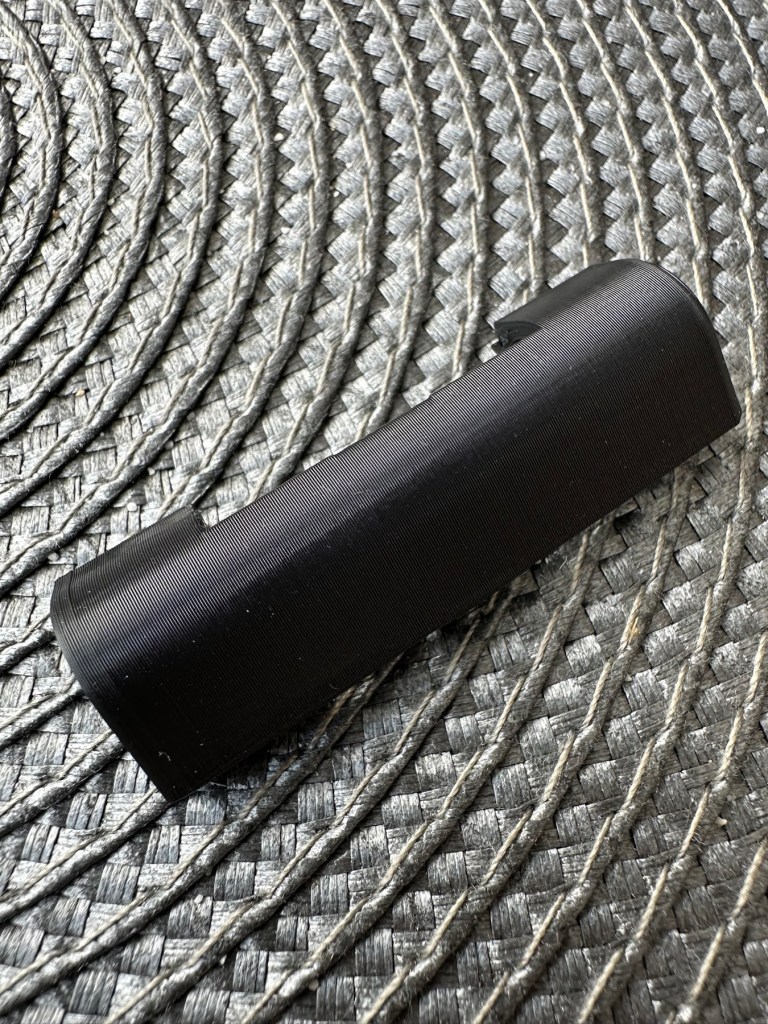
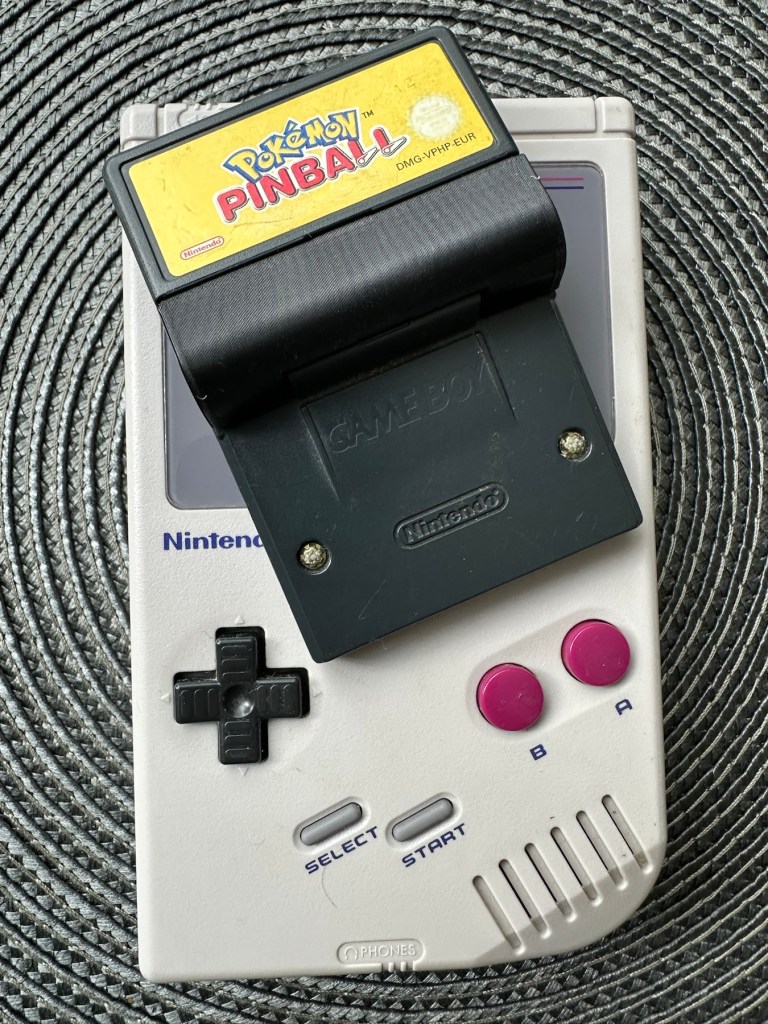
New 3D battery cover has arrived and this fits perfectly, no issues here.
Missing battery cover Clean and tidyNew 3D printed battery cover
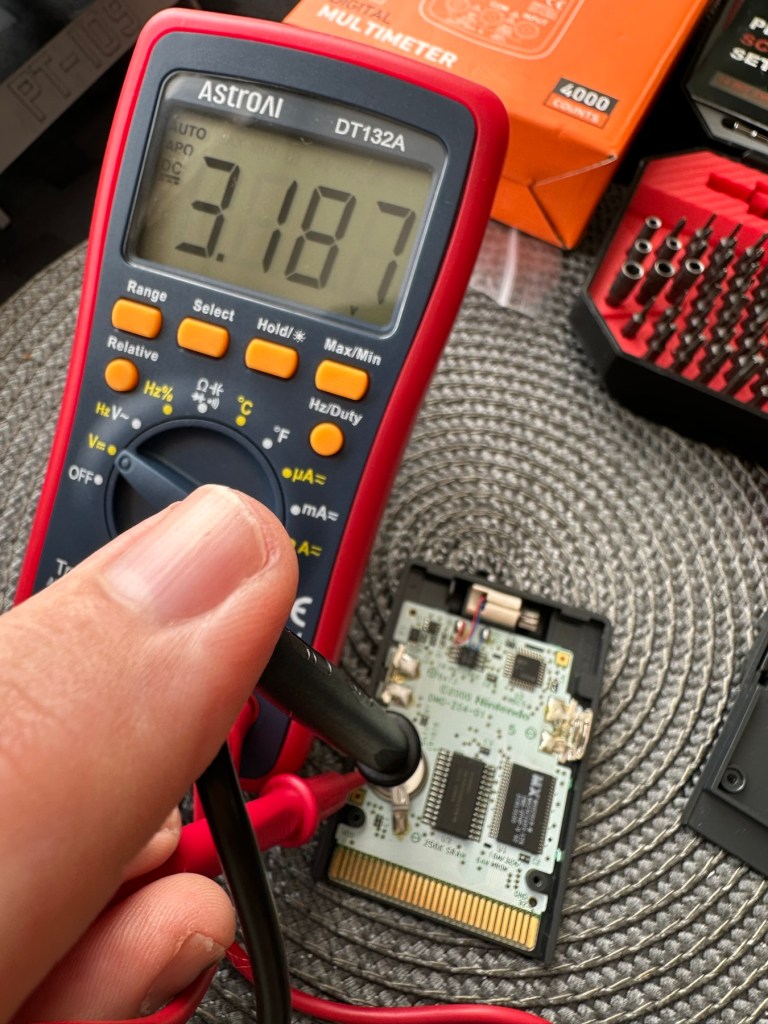
I’ve placed the unit into my GameBoy to check what occurs, and just as posted it does not progress beyond the Nintendo start up screen. I’ve opened the cartridge to do some basic checks and cleaning, the cartridge contacts have been cleaned using an eraser and some IPA, but in all honesty they were already pretty clean. I’ve checked the onboard battery and this is healthy at 3v as it should be. Cleaning competed, I recheck the game and the results are the same.
Game stops at this pointBoard levelBattery testedContacts cleaned
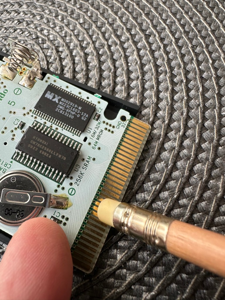
Next I’m going to reflow the joints on the ROM chip on the right hand side of the board, the one that has the letters MX on it. These pins or the ones on the RAM chip directly beside it are well known for having bad contacts and often need reflowing/tacking down. It’s something that seems to occur over a period of time on these game cartridges, just plain bad contacts.
ROM chip on the right with the RAM chip on the left, both are notorious for developing loose contacts
All items on the board have been reflowed using hot air, with extra attention being paid to the two chips described in the picture above. I removed the battery prior to doing this as the last thing you want is exploding batteries. With the battery back in place and the game now reassembled it’s now time to test.
And it works including the rumble pack feature.
Pokémon Working
I can only presume the hot air reflow has fixed an issue with joint continuity on one of these chips as expected. Excellent, another item has been saved from the bin and can now be added to my collection.
Game workingComplete with new 3D printed battery cover
Another little project to put to bed, there always seems to be an issue with these games after a good number of years where the solder joints just become unstable. I don’t know if it was the solder quality they used all those years ago or the heavy use and abuse the games endured during their hey day. At least we can fix them and ensure they are still good to go and enjoy for a few more years yet.
Another production on an iPad from my 2012 era. God knows what I was on at the time as I was doing some right old tripe. But hey ho, it’s done and it covers a particular time of my life so it has to go out there. Not just showing the good stuff (not that I do any good stuff….). I guess if I had a name such as Picasso or Banksy it would be worth an absolute fortune. But I don’t, and it’s not. Enjoy, laugh, critique, slap your forehead. At least it’s got a reaction 👍
This will be post No:1 of a series, where I attempt to buy parts of a damaged camera system to repair, reassemble and get back into working order.
I have chosen this particular camera as it was one that featured prominently in my career when leaving school and starting in the Photographic world. I’m going to buy this camera in bits, as it is modular. I’m going to try and buy parts that are for spares and repair for me to fix, to see if I can get a half decent working example. So expect a bit of a Frankenstein project here.
Bronica SQ-A
Just like my post on the Canon A1 that I previously published, this was another loan camera in my early years of photography back in the 80s. When money was sparse, colleagues usually allowed the loan of their equipment under certain conditions, one of those being,”Don’t break it”. I used this camera when I did my first studio session when a friend of a friend was setting up a business selling Teddy bears. She wanted good quality portrait photos of her work and this camera enabled me to do that. This was the first medium format camera I had ever used, and for that reason alone it will always sit as my favourite. Many people favour later models and other equipment, but this is my personal favourite. It has its flaws as some do, however this camera was significant in me learning a profession, as well as it triggering many treasured memories for me personally.
Now I want one of my own. 41 years after I first used one. But I don’t want to pay a premium price for it. In fact i wish to pay as little as possible, and that’s where it’s going to be difficult.
You can read more about the camera here: Bronica SQ-A
Requirements
As this is modular camera unit, I will need these parts to form the most basic camera, no bells and whistles as they say, just the basic version:
Lens – obviously
Main body – got to be the SQ family
Viewfinder – a few to choose from
Film back – I’m after the standard 120 roll film back
I’m looking at this being a medium term project so these items will be purchased over a currently undefined period of time, I’m hoping to buy items that require attention so I can keep the costs down, something that needs attention and repair would suit, as I can create a post regarding its repair. Individual spare parts do command some high prices so I’ll look at maybe purchasing some beat up stock that I can use as spares. I’ll keep a running total of the spend, I know I could buy a working complete unit for around £6-800GBP second hand, but that’s damned expensive in my eyes, I believe it was only £400Gbp (Minus lens) back in the mid 80s. I want to prove that a good usable unit can be built with just a little attention at a much lower and more realistic price. On the cheap if you like, as good quality photography does not need to be expensive. It might not look pretty, but it will be practical, and it will work. Most working cameras look beaten up. Most of the ones I used whilst working for a photo agency were total wrecks but took great photographs. I want to run a roll of colour and one of Black and white through it to prove i have made a working practical camera. It’s probably going to be a lengthy project, it’s going to be hellishly tough, but one I’m very much looking forward to.
From now on it will be known as….
The Frankenstein project.
And more posts will appear as the parts start to arrive and are assessed. Each part will have its own post dedicated to its purpose and repair, and a final post where it will be finally assembled and tested.
Thanks for passing by, please be sure to check back as this exciting project comes together, using the links below:


You must be logged in to post a comment.