I’m fixing this lens and came across this broken part. But what is it called? Does Chat GPT know the answer? It seems it does.
Please do not for one minute consider this an endorsement for AI, it’s not. I very rarely ever use it, and to be totally honest I keep as far away from it, as i possibly can. The only issue is, is that it gradually sneaks through the back door unannounced in pretty much any application or program that you now use. There is no escaping it really, even here on WP this week I received an invite to start using AI to write my posts and to control their content and SEO compatibility, whatever that is. Straight in the bin it went, no thanks, not interested.
I know my grammar and punctuation leaves a lot to be desired, and sometimes it is very poor, but hey! That’s me and I don’t want to suddenly appear to be a fully functioning and academic genius, as that’s just not me. I’m a Comprehensive educated drop out, that has managed ok thank you, and I don’t need some computer to portray me as something I’m not, or am likely never going to be.
Rant aside, let’s get back to the story that is based around the item in this picture.
What’s that then?
I’m currently carrying out a repair on a Canon EF 28-200 lens from around the year 2000. Whilst dismantling this lens, the above part became the item of interest as this is a piece that controls the zoom of the lens, hence this lens never really worked due to it’s inability to focus or zoom, and the item above appears to be the guilty party.
It’s broken, that is clearly obvious to see, it’s made of an alloy, possibly aluminium, and is not repairable by soldering due to the immense high temperatures that would be required. I can’t achieve such temperatures as I don’t have the equipment available to do such work. I could try forming something from scratch, that is an option but I don’t really have the time or patience to be honest to spend such time on such a tiny piece of metal. The whole piece is no bigger than 2cms long at its longest point. It really is tiny but essential for the smooth operation of this lens.
This is where the AI help comes in.
Having looked at many repair manuals belonging to Canon, I have an immense list of code numbers but nothing at all explaining what this item is or if there are any still available. I’m kind of lost and at odds as to what I should do.
In desperation, I type something similar to this request into Chat GPT:
“Long angular aluminium piece, working the telephoto element of a Canon EF 28-200 lens”
And this came back as an option:
Bingo – Courtest of Barrell Y Store – Ali express
Wow. That looks familiar!
And it is in-fact the part I am looking for, on the Ali Express site, our friends in China have one left in stock – “Click” that’s purchased and is now on its way to me.
I am now also fully aware of what it actually is, apparently it is called a “Zoom guide pillar, zoom lever, electric brush lever for a Canon 28-200 zoom lens”
Well there you go, it appears AI is good at deciphering the ramblings of a frustrated and confused 60 something. And in this case it did very well. When this arrives I’m going to give it to one of the tool makers at work to get him to make a few copies, I’m even going to see if I can get a few printed out 3D wise to see how the plastic version holds out under the demands of the lens. I don’t foresee any real issues as long as the lens isn’t mistreated in any way.
Well. That’s my major frustration of the week, and my first real face to face involvement with AI.
I’ve just purchased an old Rollei 35 XF rangefinder from around 1974. It doesn’t work, so let’s see if we can get it working again.
What the listing stated:
The Rollei XF 35 is a compact vintage 35mm rangefinder film camera made in Germany, known for its classic design and portability.
This camera is being sold as spares or repairs and does not power on. It has not been tested with film and is not in working condition; functionality of the shutter, meter, and other features has not been confirmed.
Cosmetically, the camera shows typical signs of age and use, but no major damage is visible. Please note this item is intended for parts or restoration and is not guaranteed to function.
Accessories included: wrist strap and lens cap.
EBay
Rollei XF35
I like these little point and shoots. I’ve always wanted one, and ideally I would like an original 35, but in the meantime I’ll settle for this one. Not working, only £17:00GBP, this was a bargain price for an old camera with a lens that has a superb reputation for having good optics. It’s a bargain basement price for a camera that has a lot of potential if I can get it working again. I have purchased from this supplier before and they are a good bunch of guys and girls, so I don’t believe I am being ripped off in any way. This camera dates from from around 1974.
Here’s a little bit about this camera:
The Rollei XF35 is a small 35mm full frame Rangefinder camera released by Rollei in 1974. The same camera can be rarely found under the brand Voigtlander: in this case it’s called VF135.
This camera provides only a programmed exposition, with a CDS cell powered by a small 1,35v PX 625 mercury battery. A ring around the lens must be set to the right ASA/DIN value.
The shutter is a small Copal central type one, that also works on relative aperture.
The lens is a Carl Zeiss Sonnar-derivation, built under license by Rollei. It’s a 40mm f2.3, with focus from 1 meter of distance. The viewfinder has a small frame that indicates the f-stop and the speed of the shutter that the program will use. At the center, two small yellow and red circles must overly to obtain focus on the subject.
Shutter speeds go from 1/30 to 1/650s, including bulb mode (only at f2.3). Copal shutter closes up to f16, so Rollei reccomends max 400 ISO/ASA films.
There’s a hot-shoe flash slot and the camera also includes a self-timer (circa 10s of delay). Under bulb mode, this timer can fire the shutter to a speed of circa 5 seconds.
Camerapedia
I’m expecting the camera shortly, so in the meantime I’m off to read the manual and to also look for replacement batteries that replace the now defunct PX625 batteries this camera used to have to maintain a sufficient power supply. When it arrives we can carry out a full assessment.
Assessment:
On arrival it’s a nice tidy little camera, with slight signs of use and that slight mustiness of being in storage for a few years, though I have smelt worse.
It needs a little clean, the strap buckle is a little rusted however that is easily replaced.
Inside, the camera is clean, the winder works and the exposure button works, however the shutter doesn’t fire. This could be one of a couple of issues, the battery inside that appears to be an original PX625 Mercury battery could be below power, and if it is an original this could well be the case. However the light meter is working and this is a welcome bonus, so there is a little life still in the battery that should be 1.35v when at full power.
Light meter is functioning
Let’s check this with the multimeter, before purchasing a new battery, and I can confirm the battery power sits at 1.53v?
A fully charged 625A battery
I was mistaken, it’s not an original PX625 it’s actually a 625A alkaline replacement. These alkaline batteries are 1.5v rated against the original that was 1.35v. These batteries are commonly used with these older cameras as a suitable alternative to the original battery. The only issues that are sometimes reported are that the metering can sometimes be off by about +2stops, however some people report no issues at all so it is all a little bit and miss to be honest. I guess it’s all down to trial and error with your own film stock and the camera, B&W film would probably be more forgiving. So, in this case it is not a power issue. We need to then move on to another option.
The other related issue could be sticky blades on the shutter mechanism, and that is more than possible if the camera hasn’t been used in quite a while, the old lubricants dry out over time and the shutter blades get stuck, this means I would have to carry out a service of the shutter mechanism, not a major issue just quite time consuming.
Repair:
I have liberally coated the shutter blades from inside with some isopropyl alcohol as that’s all I had available at the time. This has removed some old black gunk that appears to be old oils of some kind, however the shutter still does not operate when activated, even though all the noises are there to suggest the mechanism is actually working.
I have used a compatible tool to tempt the shutter blades open, this initially worked but they did not fall back into place with any urgency. I suspect there is residue on the opposite side of the shutter blades, so it looks as if this will have to be a full CLA – Clean, lubricate and adjust, requiring a partial disassembly of the camera.
Boy I wasn’t wrong, this is probably the deepest I have gone into a camera for quite a while, this camera really does have to be dismantled. These cameras have always been renowned for having issues deep into the cameras workings, it’s probably what has gained them a poor reputation, somewhat unfairly, but not everyone is prepared to dismantle a camera at these prices, when they can just chuck it and get a new one. However that’s not what I do here.
Let’s stop the chat and get on with it.
So we need to get inside, and the best plan of attack is from the front through the lens turret, so first thing we do is remove a retaining ring on the lens. This allows us access to the insert that controls the ASA, and where the CDS cell is located. Remove with caution as there are small wires present.
ASA and CDS module removedThen the focus ring
Three screws under the ASA/CDS module then allow you to remove the focus ring where there is a small brass plate. This is removed and then the rest of the barrel loosens, but cannot be removed….strange.
At this point I had to do a little research and source the maintenance manual and refer to it to see what I had to do next.
Maintenance manual courtesy of Rollei
After reviewing the manual it appears there are another four screws requiring removal before we can access any deeper, however these are situated under the camera “Skin” and this needs to be peeled back slightly to access.
Those four extra screws under the camera “Skin”
With these four screws removed, you now have to remove both the top and bottom parts of the camera, five more screws to allow the front plate and lens to be removed.
Base of camera removed exposing winder workings
Shutter mechanismA bit deeper with aperture plate removed
With the lens plate now movable, again I carefully move it aside being wary that there are also wires here, and not a lot of room for manoeuvring. A slight twist of the brass aperture control plate and it can then be removed. The plate below this, with the three brass dots, just clips out and exposes the thin shutter blades below.
Shutter blades only one link visibleBottom plate removed
Just looking at the shutter blades I can see there is a small link missing, this was sitting loosely to one side, it could have come off as I was dismantling the blades, who knows. Carefully put to one side the blades are placed individually in preparation for a clean. Lastly the bottom plate of the shutter mechanism, lifts out and beyond this point is the camera back, we have just a hole as the whole shutter and lens mechanism has now been removed.
All parts removed have now been cleaned with an IPA solution to remove any grease and dirt, and there was quite a lot of both. These have all been put to one side and will be cleaned once more prior to reassembly.
A period of time was spent just watching and observing whilst I continued to prime the camera and fire the mechanism to see if I could see anything obvious that was of concern. After a while I could see the issue, there is a small flywheel that was not moving, and as a result the connected shutter mechanism could not move.
Flywheel and aperture pin highlighted Flywheel and shutter blade actuator
The flywheel controls two parts of this mechanism. Firstly the shutter mechanism to move and work the shutter blades, and secondly there is a small brass pin at the top that also moves relative to the aperture setting, if this is in the wrong position, the shutter fires but will not close, this wheel is where the issue lies.
Using some IPA I get into the gearing from the base area, and give all the gears that I can access a good clean, I activate the camera numerous times to get as much grease and dirt away from the workings as possible.
Then using a very fine camera oil, very sparingly, literally a drop on top of a needle applicator, I place oil onto the cogs paying special attention to the offending fly wheel.
Oil applied with a needle applicator Oiling the offending flywheel
I have three shutter blades that are super thin and delicate that need a final clean, dry and a dry wipe prior to reinstalling. I get this done and then put both links in place, after installing the blades in the correct order.
Shutter blade reinstalled, with both links
A small video showing the shutter working
The re installation of all other parts is just a reverse action of how they were taken out, each part was cleaned as it was put back, so in theory the camera is an awful lot cleaner and free of contamination than it was a while ago. Before I put the lens plate back on the camera I check the shutter’s operation and it is all fine. Just a final calibration of the aperture settings, a check of the focus range, and just ensuring all wires are routed sufficiently, and the lens plate is ready to attach to the rest of the camera. This done, the base and top fascia plates are attached after first cleaning the focus window and light meter window. The camera is now fully assembled, it now just needs the camera “Skin” to be re glued where it was earlier removed for access.
Reassembled and just needs gluing
The skin is now glued into place.
Skins re stuck
Now I’m outside the camera I’m just going to touch up some of the scuffed areas with some permanent marker, it’s not worth stripping down, priming and repainting, to be honest I’m quite happy just doing a touch up of the scuffed areas and that is what I have done. Once it gets a clean and polish it will appear much improved, compared to when the pen is first applied, it will blend in.
Before and after pen applications
I’ve taken the old strap buckle off as that was rusted, I’ve just used the original strap ring to connect to the camera lug, I think it looks good. I’ve also added a cover for the hot shoe connector that I’ve printed off on the 3D printer.
Original ring
And that completes the repair, the last thing to do is get this camera cleaned and polished.
Result:
With a good clean and polish, this little handheld has come up looking superb.
The finished clean Rollei XF 35
With all the extra touches, we now have a superb working, resurrected camera that was heading for landfill. This has taken a lot of time and patience, something I don’t have a great deal of if I’m honest, but I was determined to get this project finished. And it is. It looks good, works good and has years of life left in it. Currently sitting at 52 years old, it has a long life ahead of it.
This camera probably rates as one of the most fulfilling and pleasing projects I have ever started upon and completed. It’s been a very delicate and time consuming job, and that I will not deny. It’s only a cheap low cost camera but it’s taught me a great deal. It’s the first complex project I have undertaken, in my new workspace, I don’t think I would have been able to complete it with my old set up. It’s been an achievement, one I am considerably proud of, an occasion when once again, it doesn’t matter how old you are, you can still learn a lot. A big positive for me.
Anyway, enough about me.
Thank you most sincerely for passing by and giving me your time. It really is, very much appreciated.
When the youngsters of the clan, drop surprise repairs on you at family gatherings.
It’s great when one of the youngsters of the clan come up to you at a family gathering and greet you thus, “Oi, uncle Dave, have a look at this for us will you?” and then they just disappear into the crowd as I’m now holding a couple of items I’ve never been exposed to before, in this instance a pair of Playstation 5 Dual sense controllers. (I had to google to find out what they were!)
Here you go “Uncle Dave”
Apparently they don’t work, or are having difficulties, and it’s now down to me to find out what’s wrong.
Now I’m not a gamer in the true sense of the word. I like, and have repaired and own a good few hand held devices that have been featured within these blog pages, but I do not own a console, I never have. However I’m lucky in that I know a few people who do have these consoles, who I can go to and test how they are behaving, but the good thing is that these controllers can also be tested without a games console and just require a computer with a USB port, and I do have one of them, a clever move by the manufacturer me thinks.
First thing I did here was to plug them in to a USB supply to charge the onboard battery. Each one has a 3.7v rechargeable battery that should give between 6-12 hrs of activity depending on how vigorously the unit is being used. When charging it glows on and off orange until it is charged and then the glowing just stops. Both these units took about 2.5 hrs to fully charge, and they seem to both be holding a good charge seeing one of them, the black version has not been used for some time.
Let’s get them connected up to a PC.
A simple good quality USB cable is the communication method between the controller and the PC. Next, you go to the address: https://dualshock-tools.github.ioand here is where you will be doing those checks on the controller that sits in your hand. Seeing I don’t really know what’s wrong with the controllers I have been trusted with, I think this is the best place for me to start my investigation as the site does do some good, and thorough testing.
I have two controllers to check so I start by plugging in the Black controller, clicking connect on the screen gets access into the memory of your controller and all the firmware detail and build date is displayed in front of you. Cool!
Just under where this information is displayed we enter the first series of tests, a bank of 8 basic function tests that check all bells and whistles (as such) are operating as they should. This Black controller passed all these tests with flying colours.
All 8 checks passed
Light checks all passedAll buttons and switches working
The checks are thus:
USB controller: here the connection is tested a simple pass or fail
Buttons: all buttons have to be continually pressed until they turn green on the screen, a simple pass or fail
Adaptive trigger: the system puts a resistance on the two triggers representing various triggers on guns and switches experienced in various games, if there is suitable resistance here the result is a pass.
Haptic Vibration: this tests the vibration motors in the controller, if it’s working then it’s a pass
Lights: all lights on the controller are cycled through displaying the whole range. Simple pass or fail
Speaker: a tone is played through the built in speaker, a simple pass or fail.
Headphone jack: a simple test of the plugin headphone jack – pass or fail
Microphone: a simple test by blowing in the on board microphone checks if it’s working, a simple pass or fail.
And as stated the first controller, the black one has passed all of these tests. Impressive. The next tests are all centred around the two thumb pads, their return to centre position and their all around circular motion and their calibration.
Left pad off centreCalibratedBefore and after calibration
The left pad was showing slightly off centre and I was able to make some minor adjustments via the program interface to correct this issue. The good news was that it is not a constant stick drift, and the mechanism does not require replacement, it is easily adjusted. With settings saved, disconnect the controller, reinstall it and re check the calibration and it should all be good. And it was. With minor adjustments made to this controller I am pleased to say it is working as it should, it is now repaired and will be heading back to its owner.
Now onto the second item, the white controller. I put this controller through the exact same testing protocol as the first one, all was going well until we got to the buttons section where this one failed. The down button on the left hand side of the controller is unresponsive, you can see this in the photos below
Failed test in the button section
Failed button highlighted on Controller and screen
All other tests on this controller were fine. Again there was a little drift on the sticks that I was able to adjust and they are now both as central as they can be, operating well through their whole range. I will go through the repair and retesting of this pad in the section below the YouTube video that I have highlighted below.
A while ago, if your game pad was playing up, there wasn’t really a great deal you could do apart from replace the thumb controllers if you were experiencing issues such as a little stick drift (when a controller is moving on its own accord). A bad case of stick drift would require you to change the controller mechanism. However, some very intelligent people within the gaming community have put together a number of packages to test your game controllers, but the one mentioned in the video below has been a game changer as such, as it also allows adjustments to be made and saved and thus extending the life span of the components within, thus reducing the need to replace and dispose of those components prematurely. Have a look, it explains the testing protocols and checks them against other programs.
The whole testing procedure checked and compared with other testing programs
Repair and retest
It’s a simple enough activity to get inside of the controller, some clips, and four screws get you inside the package, getting beyond this though to the controller buttons where we need to be is a little bit more in depth. So here we go…
I’ve dismantled the controller as I said I would, initially the process requires four screws removing, after you first gently prise off the black decorative plastic surround as in the pictures below.
Black surroundScrew on each handleScrew under each button
When you remove these screws the next task is to gently prise the two shells apart that then reveal the base of the controller
Shell successfully removed
At this point the battery needs to be removed and that is a simple plug disconnection, the battery plate has a single screw in it that needs removing. Before you remove the battery plate there are four ribbon cables that need removing, if you don’t do these then you will probably tear them and need to replace them. Believe me, I have done this in the past and ruined the tiny microphone ribbon at the very front. It’s not expensive to repair, just an unnecessary expense. Don’t rush it. Another 3 screws removed and we can now take off the top cover and get to where we need to be.
Top removed exposing fault pad area to the left
As soon as the top was removed I could see the potential issue with the controller direction pads. The pads are a rubber base with a carbon pad that makes contact with the circuit board below. Sometimes a simple clean of these pads can be sufficient to regain a connection between the two, but in this case it was plain to see that the pads on both sides were both well worn and to be honest they both required replacement.
The two contact points ringed in red that were sufficiently worn
Normally a good clean with IPA will work
As stated I did give a clean to all contact points with a solution of IPA, reassembled and tested again with no change in performance, the fault remained. I will now need to purchase a new pad assembly and replace the film circuit board below them. Fortunately these are freely available and will cost no more than £6:60GBP to replace. And considering a new controller would cost at least £60:00GBP it’s worth the small investment to restore it.
My shopping list of spares
I now just have to wait to receive these items and get them installed.
The items arrived just as in the photos above, and following the previous instructions to dismantle the unit, I have removed the old conductive film sheet and replaced this with the new one. I have also removed the silicone pads with the carbon inserts and these have also been replaced.
New conductive film Now reinstalled
Now all I have to do once I have connected the ribbon cables is to get the outer shell back on the controller. Once this is done, I can log in and start the testing process once again, connect the controller to it and then commence a full test of its functionality.
Before repair After repair
And as you can see in the above photographs, this has been a successful outcome. Where the left hand side lower button had failed, the new conductive film has addressed the issue and this handset now has full functionality and is working as it should be.
Next I’m just going to do a re-calibration, to check that the sticks haven’t drifted in anyway. If we are in a good position, we can then class this repair as successful and then it can then be passed back to my nephew to carry on shooting aliens, and he can then continue his mission to save the world.
Result:
Two controllers have now been serviced and are both working well and within tolerance. They are about to be returned their owner so he can get them back into use, killing aliens and saving the world from a zombie apocalypse (or whatever he does with them)
Not having a lot of experience prior to receiving these two controllers, I was a little doubtful about where to start and what to check. However after reading up on them, and their operation, I was able to pick up a lot of advice and information regarding their manufacture and serviceability. I like to think that I’m well clued up on these items now as I can disassemble one in minutes, replace parts and reassemble without having any screws or parts left over ( Always a good sign 👍)
And to round things off I have now been given one of his friends controllers to repair as well, so I must be doing something right!
Thanks for passing by, as always it’s always very much appreciated.
Let’s have a look at a non functional Camcorder from 2011 that appears to have bathed in molasses as it’s so sticky. Can I get it working once more? Why not?
What the listing stated:
It has not been tested but outside case is sticky. Would recommend for spares and repairs only
EBay
Toshiba Camileo X400 Camcorder
Not one of the finest quality camcorder cameras out there, but for £7.00GBP, I’m not really complaining. This camera appears to have a battery included, it has no charging equipment or anything else included, but I’m hopeful there’s not too much badly wrong with it. However as this is a platform for repairing old knackered equipment, hopeful there is something that we can get our teeth into that is sufficiently suited to this platform. All I can currently gather from the listing is that this a bit sticky, and those of you who follow this site will know that stickiness, especially on cameras is not an issue that has caused me any problems previously. Hopefully the issue is a little more than just stickiness, and as this listing has the classic EBay “Get out of jail free – seller not tested” claim, then there could be absolutely anything and everything wrong with it, we will just have to wait and see.
Here’s a little bit of background for this camcorder.
Toshiba’s CAMILEO X400 Full HD camcorder offers 1920 x 1080p video capabilities, 23X optical zoom, and other great features for taking great video and making great memories.
No matter what you’re looking at, the CAMILEO X400 Full HD camcorder takes jaw-dropping video in 1920 x 1080p resolution. You’ll be able to capture all the color and clamor of that Fourth of July parade, or your daughter’s first soccer goal. And with the 23X optical zoom, you’ll see the big smile on her face, too.
Want to follow your baby as she takes her first steps? Follow your friends as they head up that mountain trail? Record your Jeep ride across Africa’s Serengeti plain? Go for it. The image stabilization capabilities on the CAMILEO X400 Full HD camcorder ensure your ensuing creation will be hunky-dory, not herky-jerky.
Video trimming on the CAMILEO X400 Full HD camcorder makes editing easier by letting you cut out a section of the video from the front, back or both–plus start and end the video at any point you wish. What’s more, with a built-in pause button, you can stop wasting storage space and reduce file clutter by recording multiple scenes into a single file.
Your son just learned to surf and caught a nice point break for a good long ride. Want to freeze the frame for pictures you can share in an album, email or hand out to friends? Do it without interrupting the video. Simply press the Photo button* on your CAMILEO X400 Full HD camcorder and your surf dude will be immortalized forever.
Features:
1920x1080p Full HD resolution video
23x Optical zoom
3″ swiveling LCD monitor
5MP CMOS sensor
4.7 x 2.1 x 2.4 inches
Weight 300g
Toshiba
Well, to be honest that has to be one of the worst background write ups I’ve read, and in reality the tone of it doesn’t fill me with confidence, all that talk of “Dudes” and “Hunky dory and Herky Jerky” my god, who do they let write this stuff? This camera didn’t stand a chance to be honest right from its release date in late 2011.
So, let’s forget the awful promotional write up, and just like true “Dudes” try to find out what is actually wrong with the damned thing.
Assessment:
It’s arrived and to be totally honest, it’s in a right poor condition cosmetically. Very poorly packaged, I suspect the seller couldn’t wait to get it out of the door. Here are two of the better looking pictures.
The good…
As soon as you pick the unit up, the stickiness the seller wrote about becomes obvious. It’s as if this camera has been immersed in a vat of molasses, it’s super sticky and if you review the close up pictures below you will see this unit has obviously been involved in some sticky situation, in places it is still wet, with liquid clearly visible, however that liquid is in a super sticky state of suspension.
Sticky LiquidWet, with protective film still in placeDirt and stickiness Just plain filth …The bad, and the very ugly
The battery is in place, I suspect it is dead but it will need to be tested, thankfully the battery contacts are clean and luckily it appears that no liquid has managed to reach these areas.
Battery – possibly deadBattery contacts all cleanSomewhere clean..hallelujah!
Before I even start to look at anything with this camcorder, a very thorough clean is the order of the day. It’s not going anywhere, and I’m not doing anything with it, until it is in a more presentable and workable condition.
I like to use a disinfectant spray when taking on a job like this, in fact I use it on most of my old cameras especially those that have an old musty aroma. The disinfectant has cleaned this unit up very well removing all of the old stickiness and residue. I finish off with some polish and a cloth and the beast has now been cleaned and is now in a much better condition to start looking at where the problem may lie.
A good clean and it looks like a different unit
Well, to be totally honest the unit is kind of dead. There is a minimal voltage in the battery and when I find a suitable charging cable and install it, there is not a great deal else occurring. There are some lights, but they are not doing what they should be doing, I’m expecting lights to flash whilst charging, and a solid light when charged. However this isn’t happening, so let’s move on to what we are going to do to try and resolve this issue.
Repair:
For the moment I’m going to focus on the battery. We need power, so we do really have to start here, we can’t diagnose or do anything without some power. It’s a 3.7v Li-ion cell, and the camera can charge via a 5v USB supply. I’ve managed to locate a suitable charging cable from that drawer of collected cables that “may come in useful one day”, that we all seem to have stashed in our homes. When the cable is plugged in you should get some intro music from the camera, and I do. This should then be followed by a flashing light that should remain lit until the battery has sufficiently charged. However I manage to get about two flashes from an amber light and then that’s it… nothing else. So far it’s positive that we have seen some life, however we need to see if we can encourage this battery to take a little more charge.
These batteries though rated at 3.7v usually charge up to 4.2v at full capacity. I’ve just measured this one with a multimeter and it currently sits at 2.64v. In the world of batteries this is severely depleted and to be totally honest looks as if this battery is dead.
A fully charged 3.7V nominal battery typically reads 4.2V, with 3.7V-3.8V being the average voltage during discharge. A 3.7V Li-ion battery is considered “dead” or fully discharged when its voltage drops to 3.0V to 3.2V.
While many protection circuits cut off at 2.5V to 2.75V to prevent damage, discharging below 3.OV frequently will significantly reduce the battery’s lifespan.
2.64v This battery is more than likely dead
And it looks as if this may have occurred here. It’s looking as if the battery is a dead one.
However, I’m going to see if I can rejuvenate this battery by putting a trickle charge through it, just charging it in the camera from a USB 5v power supply. I will monitor regularly for changes in temperature or other issues. I don’t have a spare around at the moment so if I want to do some basic checks on the unit I’ll just have to give it a try.
Dead at 2.6v After an hour we have 3.5vAfter 2 hrs it’s now 3.56vAfter 3 hrs it’s now 3.6vSlow work
So after 3 hrs we’ve only been able to get about another 1v of energy into this battery, and as you can see we are only just into the battery depletion range. We have sufficient power to start the unit up and see a welcome screen, the zoom works. It’s clearly visible that there is a low battery indication on the screen and then it all shuts down again.
Welcome screen Battery indicators all red
There is just not enough life in this battery to sustain a 30 second video, the battery is just so worn down that I believe it is beyond resurrection. I may have to purchase a new battery to finish off this section of the post. It’s good though that we have tried, rather than just give up, and this has also allowed us to review what we have found out about the process, and the good news is that at this point it, is looking as if it is purely an issue with this battery.
The camera has cleaned up lovely and really looks like a nice piece of kit. For the moment I will put this post on pause whilst I await a replacement battery.
But…. Me being me, and not wanting to spend too much money at this point, I have persisted with leaving this battery on trickle charge. It has been consistently monitored to keep an eye on it, and I must admit neither the battery itself or the charger has been hot or even warm throughout this entire process, that is good.
Four green lights – Fully charged?
Seeing that about 4 hrs ago the battery indicator on the screen was only showing two green bars, it is now showing four bars and that indicates it is now fully charged. Let’s get the multimeter back on, and check to see what the current battery charge is and see if that gives us an indicator to show if the nominal charge has now been achieved, I’m quite excited at this – I’m easily pleased and excitable in equal proportions – I have a feeling that with patience and persistence we may have well just cracked the issue. So what is the current voltage of this battery? Well, here it is….
4.14v
Full charge achieved
Well, I’m very pleased with that, not only has it charged fully it appears to have reached pretty much full charge beyond the nominal charge. I’ve probably saved this battery from the trash heap, but I guess it will be more of a backup battery for me as I will probably purchase a new one, for my main battery, now though, there is no rush as it looks as if this one has been rejuvenated.
I’ve put a 32Gb SD card in and the screen is indicating 5 hours and 54 minutes of recording time, however on a full battery and using the minimum of activity (Not using Zoom and other effects) you can normally squeeze two hours of recording from the battery. But I’m never going to be filming war and peace, and I’m probably never going to get that kind of usage from this battery. My best bet with this battery is to not let it deplete totally, and try to keep it in a charge cycle were it doesn’t dip below about 25% of its capacity if I can help it.
I’ve tested all settings and everything is just fine. The touch screen is responsive and all setting and special effects can be easily accessed. There is nothing else wrong with this camcorder.
Available recording capacity Touch screen working well
At this point I am now happy that this camcorder is a fully working and very capable little unit, that should serve me well as I use it to make videos for my YouTube channel and WordPress site. Repair is complete and successful.
Result:
This little camera cost me £7.00GBP and it’s been a fantastic restoration as such as it has not cost me a penny more than what I have paid for it. All I have done is invest time, done a lot of reading up about the intricacies of Li-ion power supplies, and done an awful lot of cleaning as this unit was probably one of the filthiest pieces of kit I think I’ve ever worked on.
A video, of me, videoing a video of me videoing
The camcorder is now a totally different looking camera from that which I received in such a sorry state just a few days back.
A nice camcorder, clean and restored
I’m going to use this camera myself for little items that I will be publishing here as well as on YouTube. It is so wonderful to see old unused and unloved items, repurposed and given a new lease of life.
Another one saved from landfill.
Thanks for passing by, as always it is very much appreciated.
The Sharp OZ-7000, Amongst one of the first electronic organisers and precursor the PDA. Needs repair. Or does it?
What the listing stated:
Not working. I have replaced the two batteries and cannot get it to work. I have not touched the memory battery. See picture for actual item. Case is a bit sticky unfortunately with age.
EBay
First of all, what is it?
The Sharp OZ-7000 Electronic organiser / Calculator
The Sharp Wizard series, introduced by the Sharp Corporation in 1989, was among the first electronic organizers and a precursor to personal digital assistants (PDAs). The debut model, the OZ-7000 (known as the IQ-7000 in Europe), combined organizer functions with an IC Card expansion system, allowing users to install software and memory cards. Over time, Sharp refined the series with larger displays, increased memory, and enhanced features, such as infrared communications port for wireless data transfer, touch-sensitive displays, and clamshell designs.
The out-of-the-box functionality of the OZ-7000/IQ-7000 included a memo pad, a telephone pad, calendar and scheduling with alarms and repeating events, multi-time zone clocks, and a calculator, thus covering all the basic functions found in PDAs since. The keyboard was not QWERTY, although later models, starting with OZ/IQ-8000, changed the orientation of the screen and keyboard layout.
The OZ-7000 was about 6.3 inches (163 mm) tall, 3.7 inches (94 mm) wide closed, 7.25 inches (184 mm) open, and 0.85 inches (21.5 mm) thick closed, making it much larger than later PDAs. It featured a serial port (proprietary connector) to attach to a Windows PC or Macintosh or another OZ-7xxx/OZ-8xxx device, an optional thermal printer port and a cassette tape backup. The OZ-7000/IQ-7000 model featured 32 kilobytes of internal memory and a 96 x 64 dot (8 lines x 16 characters or 4 lines x 12 characters) black and white LCD with controllable contrast but without a back light. A major advertised feature of the model was the IC Cards expansion slot for accessory cards developed by Sharp.
Wikipedia
A bit of a break from the mountain of photographic equipment I have been dealing with lately, I thought I’d take a bit of a detour and have a look at some prehistoric PDA gear, as I have also done in the past, as you will no doubt be aware of, if you have ever read any of my posts on Psion organisers.
From what I can gather, this one is a little beaten up and battle scarred, and quite simply does not work. I’ve paid the princely sum of £8:54GBP after i managed to knock the seller down by a few pounds. I just now have to await its arrival before we can carry out a thorough assessment.
Assessment:
Its here, everything is as it should be apart from the base being a bit loose in one corner where the clip inside has broken, however that’s not an issue and can probably be repaired.
The broken clip
The exterior is a little sticky but again, this is just one of those 1989 rubber enhanced products where the vulcanised rubber coating has started to degrade. A post I previously published shows how I deal with these 80’s degrading rubber issues: Sticky, Rubber camera grips
Front case Rear caseBoth sides of the case are sticky and require cleaning
The unit has three batteries, under the rear shell. These are two CR2032 and one C1616 coin cell, with the C1616 being the units memory battery. These batteries will need to be tested as this unit does not start up, the whole unit is dead. The previous owner has stated that they have changed the two main batteries but not the memory battery, testing them will tell.
The three batteries
Beyond that, all catches, buttons and switches seem to be performing as expected, no cracks or major damage to the external shell, or screen area. Naturally there are signs of usage as you would expect on an item that is now 36 years old, light signs of age related wear and tear, nothing of concern that is detrimental to its operation.
Repair:
I’m leaving the broken clip on the rear shell as it is, it’s not visibly exposing anything of the interior and to be honest needs quite a bit of force to show the gap, it’s not a problem and not necessarily requiring a repair. In normal handling it is not even noticeable, so it will remain as it is.
The main fault, and I apologise in advance, as it was not really a fault, was a misunderstanding of the unit’s operation by the previous owner. When you take the back off and change the batteries, you have to operate a switch so as to not interrupt the backup of the system.
Battery backup switch there is a “B” and a “A” setting
There are two modes and these are explained below. This switch is located inside the battery compartment and is used when replacing the main batteries to prevent data loss.
B stands for Backup, a setting used during the battery replacement process. The device relies on a small, separate backup battery (often a C1616 coin cell) to maintain memory while the main batteries are removed, provided the switch is in this position.
A stands for Active (or simply the normal operational position), which is the standard setting for everyday use once new batteries have been installed.
To replace the main batteries safely and avoid losing your data, you must follow a specific procedure that involves setting this switch to “B”, changing the main batteries, and then switching it back to “A” after the new batteries are inserted.
The issue here was that the batteries had been changed and the switch was put into the correct “Backup” mode. However the previous owner had not placed the switch back into the ”Active” mode when the batteries were changed and the back of the shell was put back in place. Hence the unit would not work as in theory the batteries were locked out of use. On opening the shell up, this was the first thing I looked at, and when the switch was put into the correct position the unit sprung into life once the “On” button was pushed.
When the switch was set, power applied and the unit reset to 1989
When the unit was turned on it then reset to 1989, I was able to change the times and date, and I was pleasantly surprised to find out that the date range on this unit covered the years 1901-2099. Considering this unit was released 11 years prior to the Y2K bug of 2000, it showed some advanced thinking in the implementation of these units.
Happily updated to the current date and year
One of the issues with this particular unit is that there is no backlight on the display, the display is black and white and the only change that can be made is to the contrast. Back lights eventually arrived with later models. So use of these units was pretty much limited to daylight hours, or whilst under a light source of some kind, that said the display is very good and has a good contrast range.
The unit with an example function card installed
In use in the carpark at work
The last thing I have done is clean with some IPA to remove the years of gunk and I think this was quite successful
The IPA certainly lifted some dirt
After this I have finished off with a nice polish with some car cockpit cleaner. It’s finished this repair off just nicely.
Result:
Here we have a nicely presented, clean and fully working example of a nice little bit of personal computing history.
Has come up lovely
Front fasciaRear fasciaLooking gorgeous
So. With these older items, it’s sometimes good to just have an awareness of how these old timers operate. Get an instruction manual, study how it works, it can make the difference between selling it as damaged, when in fact there really was nothing really wrong with it. The seller could have sold this for 3 or 4 times the value that I purchased it for, but I’m not worried about that, as far as I’m concerned I got myself a bargain and to be honest, that doesn’t happen that often.
It’s a win win situation as far as I’m concerned, I win as I now have a lovely example of pre PDA technology, and it’s a small win for the environment as another piece of “Waste” has been saved from landfill.
Thanks for passing. Thanks for being there. Always appreciated 🙏
A bit of a different one here, i get into work one day earlier this week, to be told that one of my colleagues in a different area (Nottingham) will be calling with something to discuss. That call occurred today and the discussion was about his home theatre surround sound system that had packed up on him, and would I be willing to look at it for him to see if I could manage a repair. Though it’s something I don’t usually do repairs on, I said why not? I need to look into other areas of repair and as long as it wasn’t urgent and there was no urgency, then I’d certainly look into it for him. It turns out there is no hurry and he will get the item down to me in the next few days.
So I now have a task, that I am really quite excited about. And for obvious reasons I want to do a good job.
Here’s a little bit about this item
With the power to fill large rooms with THX certified sound, this cutting-edge receiver is ready to integrate and distribute entertainment throughout your home. More than a home cinema processor, the TX-NR717 allows you to access music on PC, stream from MP3 tunes, explore online radio, or connect your iPod/iPhone to one of two USB ports. You can distribute any of these various stereo sources to other rooms for house-wide entertainment. With a total of 10 HDMI connections, this receiver converges HD content from all your components – even your smart phone media via a front side MHL/HDMI – and provides easy input selection with InstaPrevue technology. HDMI also enables intuitive GUI with overlaid quick set-up menu. Video upscaling to 4K, Audyssey DSX seven-channel sound expansion, and Audyssey 2EQ room correction are all included. Sound quality is quite simply the best in class, with powerful WRAT amplifier, three-stage inverted Darlington circuitry, and discrete output stage components delivering an otherworldly entertainment experience.
Onkyo TX-NR717 – AV network receiver – 7.2 channel – black
Release date: April 2012
Onkyo
I’m looking forward to this project, a little out of my comfort zone, but it’s the best way to learn about how these things work. And I need some exposure to these types of systems and the issues that can occur within them.
Assessment:
This unit has just about reached its teenage years, and if this can’t be repaired then the owner will be looking at his alternatives. However replacement units have also grown in both features and price now, so if this current box of tricks can be given an extended lease of life then everyone is a winner, and one less item gets to go to landfill.
I have downloaded both the instruction manual and the service manual, so I am equipped with a full list of components as well as the official schematic diagrams of the circuitry layout. I’m suitably prepared for this one.
The report from my work colleague is that it was working fine up until a week ago when it would just not switch on. He has replaced the two quick blow fuses that he saw when he opened the unit, however the issue still remains. He hears clicking when he turns the system on, this could be an issue in the standby circuit, however I will have to wait to have the unit in my possession to investigate this any further.
Straight to the point…just how I like it
Just got a message from one of my colleagues at work to say the parcel from Nottingham has been collected. Just love the straight to the point way these guys inform me of any safety issues and concerns they may have 😂
More surprises
And on opening the box, more surprises. Biscuits, they are my downfall, and don’t ask about the Aubergine, we won’t go there, that’s a private joke 🤦♂️
A bit dusty
Right, serious head on now and I’ve plugged the unit into the mains and without touching anything at all, all I can hear is a metronomic clicking that appears to be emanating from the power board circuit area. This will be my first port of call.
Repair:
There are two well known issues regarding these units and I am going to look at both of these before getting in any deeper. The first issue is around the relay and its associated 150 Ohm resistor on the main power board, the second issue is around a defective capacitor on the standby board, and eliminating one issue will either highlight, or clear the other. If both issues are addressed with no change to operation, I will have to look in to the issue a little deeper.
Issue one relates to a problem with the relay on the main power board. Most people don’t realise this but pressing the power button on an Onkyo receiver does NOT turn off the power. The power button merely sends a signal to the MAIN CPU telling it to close a relay (to turn the system on) or open a relay (to turn it off). When you press the power button on an Onkyo and nothing happens (no clicks, no brief lighting up of the front panel) the root cause is often a blown coil in the main power relay.
Main relay is the item under the thick coating of white silicone at the top of the picture
Beside the relay to the left is a resistor that should be reading 150 Ohms. This particular one is reading 144 Ohms so is reading a bit lower than expected. This could be sufficiently low enough to allow the relay to fail. So at this point this looks like a possible point of failure. Either way they need to be replaced before we can advance any further.
Silicone removed. The faulty resistor is within the red circle
I need to obtain these parts, the relay will need to be shipped from China, and I need to check my resistor stock to see if I have a suitable replacement resistor. The relay also should have a similar resistance to the resistor beside it, the healthy range for the relay is between 80-200 Ohms.
Both components removedThe components
I have removed both components from the board to test them out of circuit.
The resistor beside the 9v relay is a 150 Ohm rated resistor. This one reads at 144 Ohms and is to the lower end of the rating of +/- 5%, it would probably suffice, but i’m going to replace this one just in case. The only other resistor in this circuit is a 47 Ohm resistor and that reads exactly as it is rated, so there is no issue there. I believe the bone of contention here is that the relay is 9v sitting upon a 12v power rail. This is probably the reason issues have occurred with these units in the past, and looking at a number of forum posts, it is quite acceptable, even recommended to use the higher voltage 12V versions. I’m sticking to the original design on this repair though, I can only presume the 150 Ohm resistor placed just before the relay has something to contribute in controlling the operation of this relay. Maybe that’s a design fault within this model, I just don’t know!
144 OhmsThe resistor I will replace
I have tested the relay using a multimeter and a 9v battery. I have used the battery to short across the power poles where I can hear the relay clicking, but when the relay is on there is no continuity across the other two pins when there should be, this isn’t happening so I suspect this relay is stuck in the open position. The Ohms rating across the pins shows 336 Ohms, so i am lead to believe this could be a problem with the coil inside it, as it shouldn’t really be that high. I understand from what I have read, that a rating between 80-200 Ohms is classed as acceptable, and outside this range could indicate that there is an issue. I’ll just have to wait until the new relay arrives and carry out some tests to see the comparison between the old and the new relays.
336 Ohms is that an issue?
I’ve dismantled the cover from the relay to get a look at the coil. In the little video below you will see the coil switching, however you will also see the contacts meeting but there is no continuity. The contacts have a coating of contamination on them probably from age or arcing, it looks like a carbon deposit, as when they adjoin there is no contact made, no flow or continuity, unless you put light pressure on the contact and then you get the continuity. It is at fault, it shouldn’t be doing this. A clean of the contacts might breathe some life into it, however give it a couple of months and you’d probably have to remove it again, and the contamination isn’t the only issue, don’t forget the relay reading that appears too high. A new relay costs less than £4:50GBP delivered from the other side of the world, so I might just as well go for a new relay. It makes sense.
Inside that failed relay
I’m not going to venture any deeper into this unit yet, not until these components arrive and I can get them back into place. I want to move through this fix confidently and slowly, have a better understanding of what is going on and not leave myself confused with bits and pieces everywhere, clueless to what is occurring. I wouldn’t achieve anything by working like that. Knowledge is king here and I’m here to learn. And I do now have the schematics available to follow.
I’ll have to wait about 2 weeks for the relay to arrive so I’ll just have to put this repair to one side and on hold until then.
Ok the new relay has arrived and the first test I did on it was to take an Ohms reading of the coil side. Now if you have paid attention, you will have seen that the old relay was reading 336 Ohms when it should be somewhere between 80-200 ohms. This new relay is reading 158 Ohms and I feel a lot better about that, it falls right in between the expected spec.
Old relay reading on the left versus new relay on the right
And if you want to see the relay actually working and displaying continuity then have a browse at this video below, the polar opposite to the first video I posted above 👆
The new relay with good continuity
The resistors I ordered have now come through and have been tested, I have a couple of candidates displaying better test results, so we can now look at getting these two components back in place to see what occurs.
I’ve put in place a new resistor, slightly higher value than the previous one coming in at 147.4 Ohms. It falls within the 5% tolerance so should be fine.
147.4 Ohms
The relay has been soldered back in place, really simple just four points to solder and we can now reassemble the power board back into the chassis.
Attach transformer and ac jumpers Board secured back into chassis
I’ve taken the unit into the garden at my wife’s request, as I have to use some high pressure air to give it a good blast to get rid of some dust and furballs. This has worked well and quite a dust cloud was witnessed across the garden, it’s fair to say it’s a lot cleaner inside than it was.
I’ve now put the case back on and the unit is now sealed from prying eyes and inquisitive fingers. I’ve given the entire case a good polish and I must admit it is looking nice and shiny and very presentable. I just have to hope and pray that it turns on. I see no reason as to why it shouldn’t but you just never know. You can always fix one problem only to be chasing it around the system as it develops into another fault, repairs can sometimes go like that.
Let’s plug it in and see what happens 🤞
Result:
I’ve plugged it in and turned the power on. No bang, only silence, just a single click when the power went on, this is good. When the power is turned off you hear the standby relay do the same, all is as it should be.
Front RearFrom above
The standby relay has clicked in when turned on at the power socket, and is not repeating that metronomic sound that was there originally. Superb. Now to turn the power button on, on the front panel.
We have a display. Excellent it is working.
StandbyDisplayAll buttons operational
All buttons are operational, I don’t have the surround sound speakers as they are at the owners house in Nottingham, i also don’t have the remote here that also allows me to do other tasks, however that is not important as the unit is now operational and displaying what it should, and once it goes back into his media wall with all his speakers and other related sound and Av equipment, i am confident beyond doubt that it will be operating just as it did prior to this issue developing.
I will be handing it back with the advice that should the issue occur again we look at updating the relays with new 12v versions to replace the current 9v ones. But I doubt the problem will re occur, and this repair should see out the next few years at least and by then this unit will probably be sold, or passed on to someone else when he decides to upgrade his system.
Below is the little video I sent my colleague showing him the unit now working
It’s now working
But for now, it works. I am pleased as punch with this repair as I have stepped out of my normal comfort zone here. I have been extra vigilant, studied many a schematic diagram and learned a lot from this project. I didn’t rush ahead of myself and took this repair one little bit at a time, testing all along the way and addressing each issue in the order that it has arisen. And I’m damned happy with that.
It’s been a learning project for me, and I’m glad I’ve undertaken it. Life is for learning, and I’m living that life.
Many thanks for passing by, as you well know it is always very much appreciated.
Edit:
Today the 29th July I have had a message back from my colleague to say that he now has the unit back in his media wall. And I’m pleased to say it’s working perfectly. He’s very pleased and so am I.
Back in place and working fine
He’s pestering me to bill him, but I’ve told him that I’m only taking one currency and that’s not money or crypto. No, my method of payment will be in Biscuits. I told you I’m a Cookie Monster and this entire repair only cost just £4:17GBP. That’s not a lot of Cookies, but it’s credit in the bank if these guys need any further repairs carrying out. Word of mouth, works wonders.
This auction is for a used cased Sinclair Cambridge Memory pocket calculator and original case. The item is in very good cosmetic condition as is the case which still has its instruction sheet. The item is powered with 4 x AAA batteries (not supplied) and does work although 1 of the digits is faulty and does not display (see pictures) plus the number 5 digit is not working. Please refer to the pictures and description provided before bidding.
EBay
It’s faulty…obviously
So it does work, but it doesn’t? This calculator is a model one memory calculator, that dates from around July 1973, ( Actually May 1975 see photos below) and is one of the earliest available mass produced electronic calculators available in the UK at the time. And it was produced in collaboration with a guy called (Sir) Clive Sinclair, who in the following decade would become synonymous with tech development in the UK. It retailed at £29:95GBP, and given the rate of inflation, its cost today in 2025 would be a staggering £463GBP. Wow!
Courtesy of Vintagecalculators.com
I love collecting old calculators, I couldn’t afford one back in the day when they arrived on the scene as I was only a child and probably only on about 20 pence a week pocket money, and savings and investments were not even known to me at this period of my life. The thought of saving that precious 20p a week for the next 150 weeks wouldn’t have even remotely crossed my mind. What no sweeties?
But I can buy them now, so no big issue!
So this one has become available, and I’ve been tracking it for a week or so, there were nine other people watching but I secured it for a total including postage of £14:49GBP, and I’m happy with that, it’s a piece of retro history for a very good price. Even if it remains faulty, or should I say working but not working?
This unit obviously has its problems, the button number 5 doesn’t work and one of the led digits is also not functioning. Hopefully I can get these issues sorted and soon have the calculator back up and working as it should. That would be nice. I’m looking forward to this little project.
Assessment:
It’s arrived and it’s a lot smaller than I anticipated. It has a separate hard protective case, which is a nice touch and a small info sheet on its operation. Cosmetically it’s in a good condition with just minor signs that are age related. There are no gouges or scars so it has been treated well, though it’s not pristine.
Two buttons unresponsive and one LED
Batteries go in ok but, I believe old style AAA batteries were a little wider than those used today and would sit a bit more snuggly in the battery compartment. As you can see there is a little wriggle room here, and springs at both ends need adjusting to help prevent this. I may have to use some spacers so the batteries sit tighter in place.
Gaps between batteries – means movement
The switch is a bit temperamental and can be seen quite plainly from the battery compartment. It looks strangely out of place with no batteries in place.
Switch offSwitch on
It is such a basic design solely relying on tension of a small metal plate to short across the connection points. Should be a simple enough issue to sort.
There is a little battery contamination on one of the battery contacts, again this shouldn’t be too much of an issue and should clean up ok with some IPA.
Some battery contamination
It was originally reported that there was one unresponsive button this being the number “5”, there is also another unresponsive button, the multiplication “X” button. There is also one LED indicator, the 4th one in from the left hand side that is not operating. Add to this the issue with the On/Off switch and the contamination, and the original faults reported in the original sales pitch have now doubled. I just wish people would spend more time going over the issues and then give actual accurate feedback as to what the real faults are, it would make for a far more pleasant buying experience. Rant over.
There doesn’t seem to be a single screw holding the body together, I just hope it isn’t all heat welded.
Let’s try to get inside.
Repair:
Well it cracked open quite nicely with no issues with just a plastic flat prise tool. The main board just sat comfortably in the unit, secure, and not a screw in sight. Strange as time moves on some of the games units I come across have best part of fifty of the little blighters to remove before you get anywhere. sometimes the old way is good.
Bare boardOpposite side of boardDate is May 1975
The dismantling of the keyboard is a little complex and you have to take time and make sure you know how it’s going to go back together, it’s just a bit fiddly. The board is quite straightforward and as soon as I see some of the IC’s it dates the unit perfectly. The chips are dated May 1975, and that is about 18 months younger than what I originally thought, it’s quite informative to get inside and learn occasionally and this is just as good as having a birth certificate presented to you. All good stuff.
I’ve proved that there isn’t a problem with the missing digit on the display as using my multimeter in diode mode I am able to prove that this LED is working fine.
LED working
The picture shows just one part of the display range on this particular digit, I can assure you all other sections of the display are also working.
Regarding the case with the buttons not working. I have checked this out for continuity and both digits go through the same portion of the main IC and there doesn’t appear to be any broken traces. It’s a strange one but I have also found some really poor solder joints that are either cold joints or just poorly soldered from the start, there are a couple of resistors that need re soldering. It may be nothing at all, but it needs attention, a full reflow wouldn’t go amiss or take too much time.
Faulty resistor joint
I’ve reflowed the entire board due to there being a few cold solder joints.
Full reflow completed
On top of this I have taken off two old capacitors and tested them out of circuit, and both were out of their operable range of +/- 10%. As a result of this I have replaced the offending components with comparable new ones.
Old capacitorsNew capacitors
Even with all these extra tasks being undertaken there is absolutely no change in the way it operates. Nothing has gotten worse, the faults that were originally there still remain. I have done some research on line and carried out some further tests and checked expected voltages, most are within range except one that appears to be less than its expected value. After testing everything on this board, every component I can only surmise that one of the three chips has failed, I suspect very much that this, the main chip, a CZL550 integrated circuit. Otherwise known as “Calculator on a chip” is the one that is at fault.
A CZL550 chip
To be quite honest these chips are fairly rare and command a price far in excess of what I paid for the original unit, and I don’t really want to do that. I think I’ll wait around to see if I can secure another faulty unit to complete this repair, so in the meantime, and until I can secure such a unit I will put this repair on hold.
Result:
Well, it’s not what I wanted but sometimes you just can’t win with some of these old projects. In no way am I walking away from it, it’s just that the parts are so difficult to get hold of that you really do have to just wait until a sufficiently faulty one comes up for sale. And that could be days, it could be weeks or months. So for now i admit defeat, but it will not be going to trash. It will remain in my ever expanding “To do” box, for me to pick up on at a later date. And when I am in a position to move this project on, I’ll pick it up in a continuation of this post.
Many thanks for passing by. It’s always appreciated.
Simple as that. And yes it’s a tiny radio but in excellent condition cosmetically.
Bush handheld
On inspection it’s obvious that the micro USB port is damaged and will need replacing.
Broken micro USBWhat’s wrong?Power board
I’ve ordered some replacements USB ports from our friends in China so I’ll have to wait a few weeks before I can progress this project any further.
Micro usb ports
The ports have arrived from China, so let’s look to see if we can repair this unit.
*This project has been on the back burner since May 2024. 13 months later and I’m now on it*
Hello all, time to clear that backlog and what better place to start than here. I do in fact have two of these with the same problem so this is a two for the price of one project.
This should be a simple case of replacing the faulty charging ports that are both micro usb ports. They are small believe me.
Old port removedNew port that has to be fitted
There has to be some preparation before we can get the new port on. Using a soldering iron and flux and a little solder wick, I clean the old board remove the old solder and give a good clean with IPA. I then prime the small connections on the rear of the charge port with a little solder. Now I put the port to the board and tack on the earth points. Then using a rework hot air gun I blast the port at about 350 degrees Celsius and hold the port in place with some tweezers until I see the solder glisten and melt around the port. I take the heat off and let the solder set before moving the tweezers and when it’s cooled a bit I check that it’s setting straight, all connections are good and solid. I then just add a tiny bit more solder to the anchor points for strength.
Whilst this is cooling down I check the status of the battery. It is a 3.7v rated battery and is currently holding a charge of 2.8v. It’s a little low but far from being dead. The second battery shows a similar charge.
Battery level
After the solder work has cooled I use my battery pack connected to a small ammeter to see if the radio and more importantly the battery is demanding any power.
Power cable connectedWe have a power demand from the battery.
Well that’s good news, 5v in and the demand from the battery is 0.96 of an amp. The battery is charging. And the fix is as simple as that.
Two perfectly good radios
A little bit of soldering aerial contacts and a couple of other wires back into place and the whole unit clicks back together. Two screws inserted in the rear and time to switch on. Both radios tune in perfectly and the sound is surprisingly good for these little units. I’m keeping one in my work space at home, as I love having some music around me, I’d sooner listen to the radio any day as I hardly watch TV. The other radio will go into my work locker for when I’m working nights or in the workshop.
In my work space, but it won’t be staying here…
Im very happy with this little project, it only took about an hour and I don’t know why I left it so long. Another couple of items saved from the tip, it amazes me that these units probably all suffered with the same problem of inferior parts that failed early on in the radios existence. Kind of scares me just how many did go to landfill.
Two cracking little radios
Well at least these two are going to carry on for a few more years yet. And that’s a positive in my eyes.
Fujifilm Instax 100 Instant Film Camera – Faulty Untested See Lens Shutter
Otherwise clean,
battery compartment is clean,
unable to test so selling for spares or repair considering the lens shutter
EBay
Instax 100 Instant film camera
I’m a tad annoyed at myself here as I had arranged a good price with the seller but because I was too eager I pushed the wrong button and purchased at the original advertised price. The seller must think I am a right plum, and I’d be inclined to agree with him. That said I’ve secured this for a good all in price, and it will be a nice addition to my collection. It’s a 26 year old camera, and i’ve been looking for one of these particular cameras that use the wider format of Instax film for quite a while, but even the damaged ones command hefty prices. I’ve paid an all in price of £28:55GBP here when I should have paid £23:55GBP. Never mind, lesson learned and don’t be so hasty in the future. They can command a good price as can be seen in the photo below:
Some recent sale prices
Here’s some info about this camera:
The Fujifilm Instax 100 was released on May 1st, 1999. It has been replaced by the newer Instax 200, which is very similar except the flash is on one side rather than directly above the lens.
Focusing: Motor-driven 2-range switching (0.9 to 3m/3m to infinity)
Power supply: 4 LR6/AA-size 1.5V alkaline batteries for around 10 film packs.
Dimensions: 171.5 x 91.5 x 119.5 mm
Weight: 650 gr (without batteries, strap and film pack).
Camera-wiki.org
Now this one is being sold with what looks like only one fault that the seller is concerned with and that being a shutter problem. From experience and as can be seen in this recent post of mine: Another Fujifilm Instax mini 8 I know that this is not a “Lens” issue it is in fact an issue with the iris that protects the lens, and is probably as a result of a small spring being disturbed in that area. It’s quite a simple fix and if it is the only fault then that would be quite some result. However, this is EBay that we are talking about and there could be a number of further faults we haven’t been informed of. Now I will just have to be patient until it arrives, there is no other choice.
Assessment:
It’s a big one. Compared to the other Instax mini cameras this one is very big. It’s probably 1.5 times bigger than your standard SLR. It’s big. And weighty!
It’s clean…ish. And there seems to be a strip of plastic, a gate as such missing from the top of the camera near the exit slot. This wasn’t mentioned and I’m quite annoyed about that. When batteries are put inside it makes all the noises, but the action isn’t smooth in the lens extension range. This probably ties in with the advertised issue of the lens iris operation. I’m thinking I paid well over the odds for this particular camera, I’ve been conned here, lesson learned.
There could well be multiple problems here, and if that missing piece on the top is anything to do with light proofing, then we could have an issue. Anyway we will cross that bridge when we come to it. Initially I’m going to stick with the original fault, so let’s attack that and worry about any other issues if and when they crop up.
Repair:
The more I get into this camera the more I find wrong with it. The main issue of the faulty lens iris is a fiddly one. You prise off the last section of the lens turret and the iris mechanism comes away fairly easy.
Mechanism removed from lens turret3 tiny springs all disconnected from the mechanism
But then three tiny springs just fall out and this is why the iris didn’t work. Trying to get them in place is a puzzle itself, as no sooner do you have one connected then another drops off. It’s a fine balancing act to get them all back into place. When they are all reconnected it’s a very delicate operation to get them back into place. And even then you have to go to the inside of the camera to ensure that the lever inside that operates the iris, is aligned to the iris mechanism that is being installed back in the lens turret. It’s a fiddly time consuming job.
All springs attachedThe lever on the inside that has to be in the correct position when the iris is attached
Iris now working
At this point the rear fascia and associated ribbon cable need to be removed to facilitate this repair. That’s when a piece of broken plastic falls out, it just so happens that one of the posts putting tension on the print rollers has broken. Great. Another problem. I’ve quickly fixed this by using some wire to act as a retention point. Bodge? Yes, but there really is nothing else that can be done here as the plastic case is thin and brittle. I have used some silicone grease to lubricate the cogs and the whole movement is now a lot smoother. It Will work. of that I am confident.
Broken plastic post, spring out.Wire bodge, spring now back giving tension
Result:
Well it works but it remains one of my most disappointing fixes due to the dishonesty of the seller. I know, if you buy off auctions it’s Caveat Emptor as they say, I preach it enough but this time I was caught off guard. Lesson learned. But I remain disappointed. Multiple faults, sold as just the one when in fact it also had bits missing that were not declared, very misleading in my opinion. Maybe in future I need to look deeply into these purchases before I give any feedback, i need to change my operation as I was truly shafted here.
Polishes up nice
It does everything that it should, the motor and transport system work, the iris now works, shutter is good, and flash operates. I’m confident that the camera is working fine but I haven’t tried any film through it yet as it uses a bigger format film and is quite expensive, and I’m not forking out for any just yet. Maybe when I get another wider format model to look at I will pay out. Just not yet though. When I do get some film through it I will amend this post accordingly.
I’m off to calm down a bit now, thanks for passing by, I really do appreciate it. Have a great day.
Fujifilm Fuji instax mini 40 instant camera . Functional, but flash NOT working .
LISTED REPAIR OR SPARES . NO RETURN .
THE CAMERA IS TESTED AND WILL,POWER UP AND TAKE A SHOT AND EJECT A SLIDE CORRECTLY. Please watch uploaded video .
HOWEVER THE CAMERAS FLASH IS NOT WORKING . This is the reason I have listed the cameras as repairs or spares.
Hopefully someone knows about these cameras and knows whether the flash unit just needs replacing or if it is an electronic fault that needs sorting out can fix it . Otherwise the parts will be useful to someone who repairs these .
No batteries or film is included .
The camera body is in very good cosmetic condition. There are only light surface marks in terms of signs of use . . Please see images as they are part of the description.
The red light to show the camera has powered up lites up when the button is pressed to extend the lens and turns the camera on .
When you close the lens down it locks securely into place .
The frame counter is working .
The film compartment is clean and the rear door shut correctly and securely.
Battery compartment is clean and the battery cover locked into place securely.
The camera is powered by to easily available AA batteries ( not included) .
EBay
The Instax mini 40
Now that’s what I call a great descriptive sales pitch. And that’s because the guy is a professional seller of photographic equipment. I’ve seen the video he posted and all the above is true, it really is just a problem around the flash. Maybe it’s an easy fix? I suspect not but either way it will be an interesting project.
Here’s a little info on this camera:
Hitting the market in April 2021, the Fujifilm Instax Mini 40 takes the updates the Fujifilm Instax Mini 11 introduced but wraps them up in a cooler, more retro-styled instant camera body. Instant film fans will probably love it and with its improved design, there’s a chance that those who aren’t instantly drawn to this form of photography may just want to have a play around with the Fujifilm Instax Mini 40, too. It does cost more than the Fujifilm Instax Mini 11, though, so you’ll have to decide if the cooler design is worth an extra £20.
+ Pros
It’s fun
Great party camera
Easy to use
Looks cool
– Cons
Film is expensive
Viewfinder could be better
Powered by AA-batteries
Ephotozine.com
I first of all went in with a cheeky bid of £15:00GBP that the seller originally turned down, so I then put in a high bid of £18:00 and as no one else was wanting it, it actually sold for £16:00, just £1:00 more than I’d originally offered. All in all the cost with the postage was £19:45GBP and I’m really pleased with this. Im surprised though that there are flash issues in a unit that is only just four years old. As you can see in the photo below recent sale prices have been strong and a great deal higher priced than what I have just paid. These are certainly popular little camera’s with the younger generation.
Recent sale prices have been strong
I guess we will just have to await its arrival to assess the flash issue. I’m very confident that I will be able to get this camera up and running again.
Assessment:
Out of all the Instax cameras I have dealt with lately, this has got to be one of the best ones I have had my hands on. This is a mid range instax camera that is more sober in colour aimed at those who enjoy their lomography or better quality instant photography. It certainly looks good, and to be honest I’d rather carry this one around rather than a bright pink one.
Looking nice and sober
As posted in the description above it is in near perfect condition and a quick Look at the flash head shows that the flash bar within the unit is broken.
Flash bar brokenConfirmed broken when removed
Let’s get on with replacing this damaged flash unit.
Repair:
Let’s get it opened up.
Dismantling
People laugh at me when i tell them that playing around inside these units could kill you. I can understand the contempt aimed at me for such a statement, when I’m carrying a bright pink camera that hardly looks dangerous. Just look at the voltage still in the flash capacitor though once I have opened it. Savage.
Residual voltage of 267v still in the flash capacitor
270v would quite easily send you across the room, if you had a heart condition it would probably be game over. I’ve learned my lesson in the past so I ensure I use a capacitor bleed probe before I go anywhere near one of these flash capacitors. The capacitor on this camera is rated at 320v, not to be messed with. Beware. What’s more impressive is that all this energy is supplied from two 1.5v AA batteries. Clever stuff.
I have a donor flash bar in an old spare unit. I have carefully unsoldered its connections and gently removed the very thin glass tube from the donor unit and placed this in the one situated on the new camera.
The donor unitIn place and soldered onto the board of the repaired camera
Carefully, once inserted into the flash reflector, i have soldered it back onto the board. All looking good. However I need to test the flash so I temporarily put the case on, bung in two batteries and turn the camera on. Press the exposure button and the flash fires perfectly. Happy days. I now can confidently reassemble the camera back together, and I’m pleased that when this is done there are no screws left over. All small wins.
I have some film available so there is no better time than the present to give it a try.
Result:
Nice flash – working Working perfectly
I’ve loved doing this repair, this is a good quality, great condition, and now in perfect working order camera, brought back to life with many more years of use left in it.
But it could have been just chucked in the waste. I’m keeping this one for my collection as it’s a fantastic example acquired at a very good price. Thirty minutes of attention is all it took.


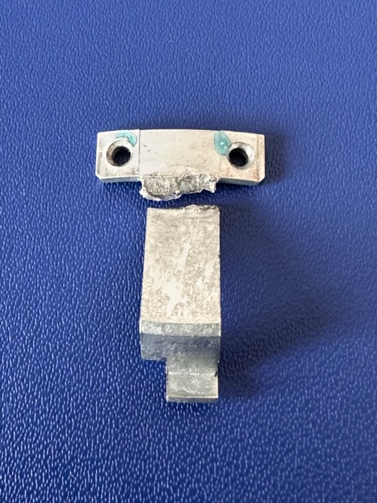


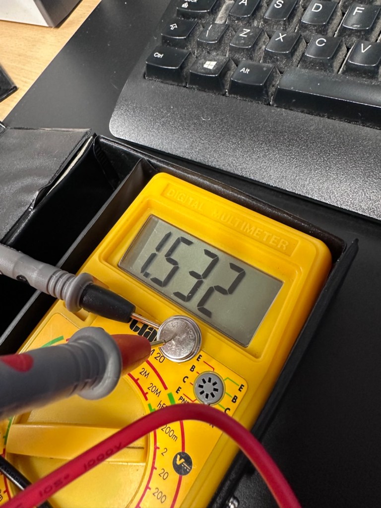
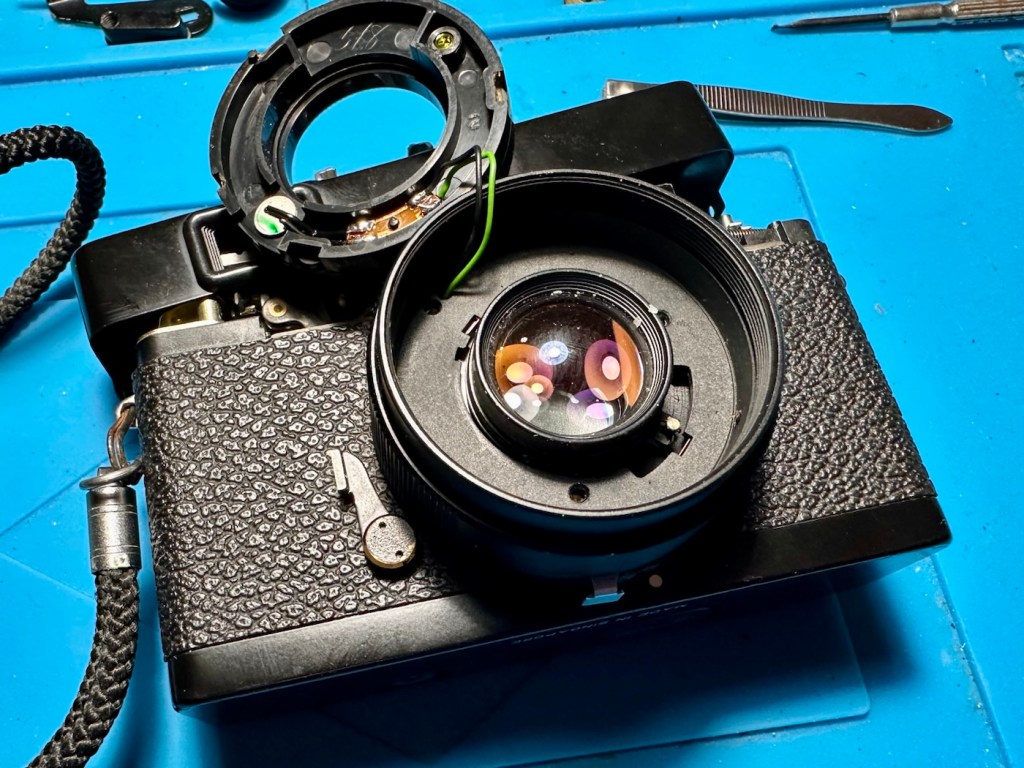
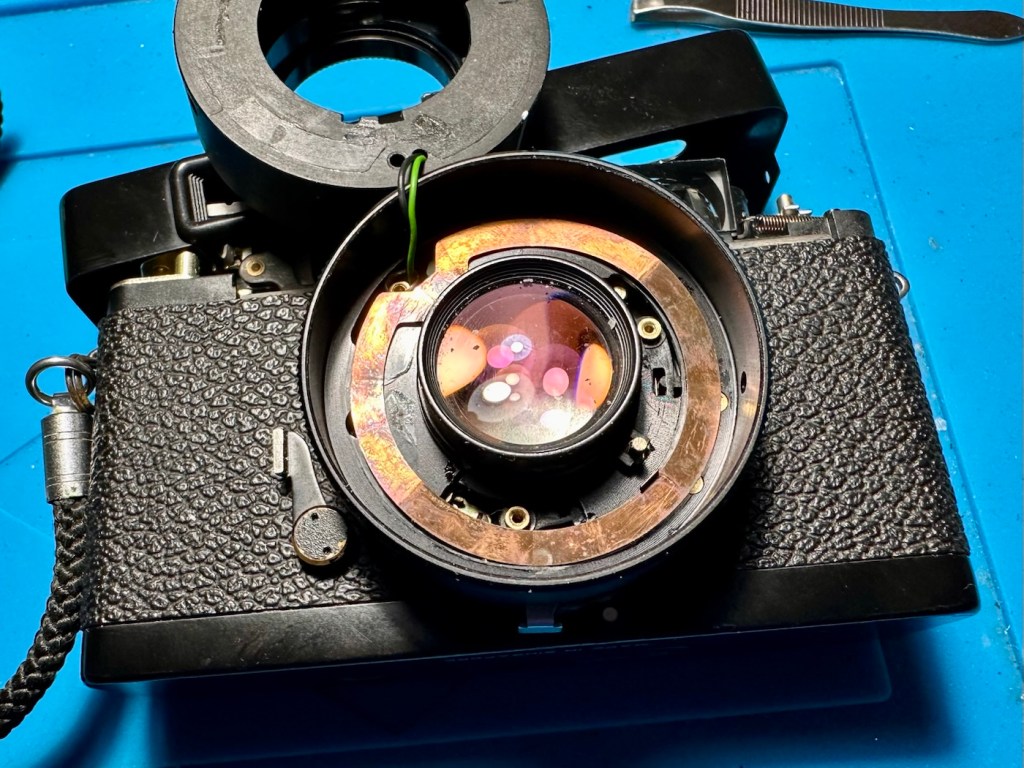
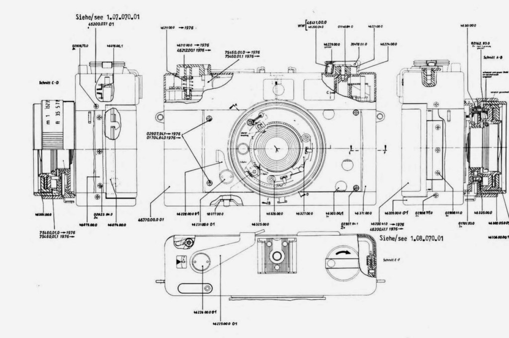
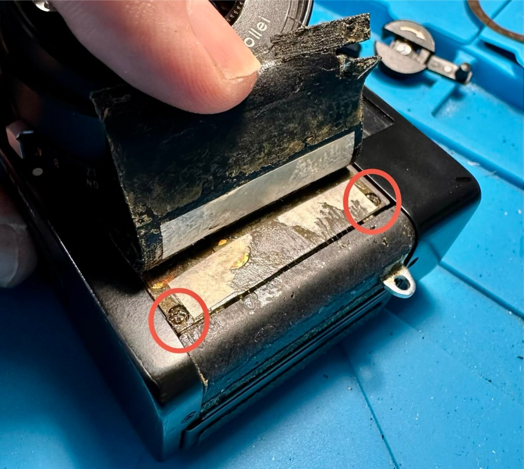
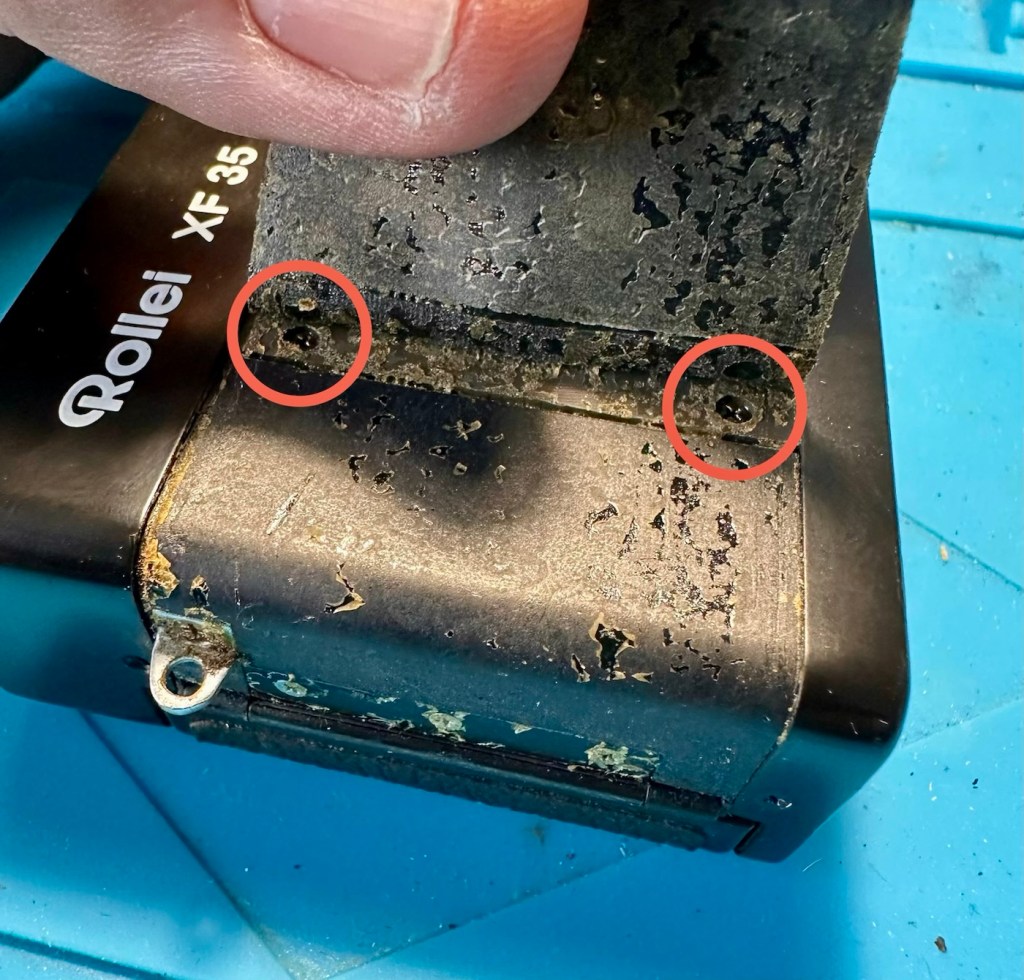
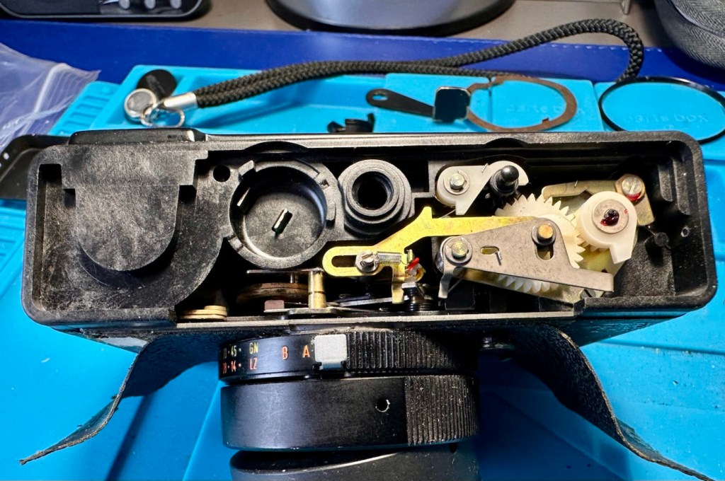
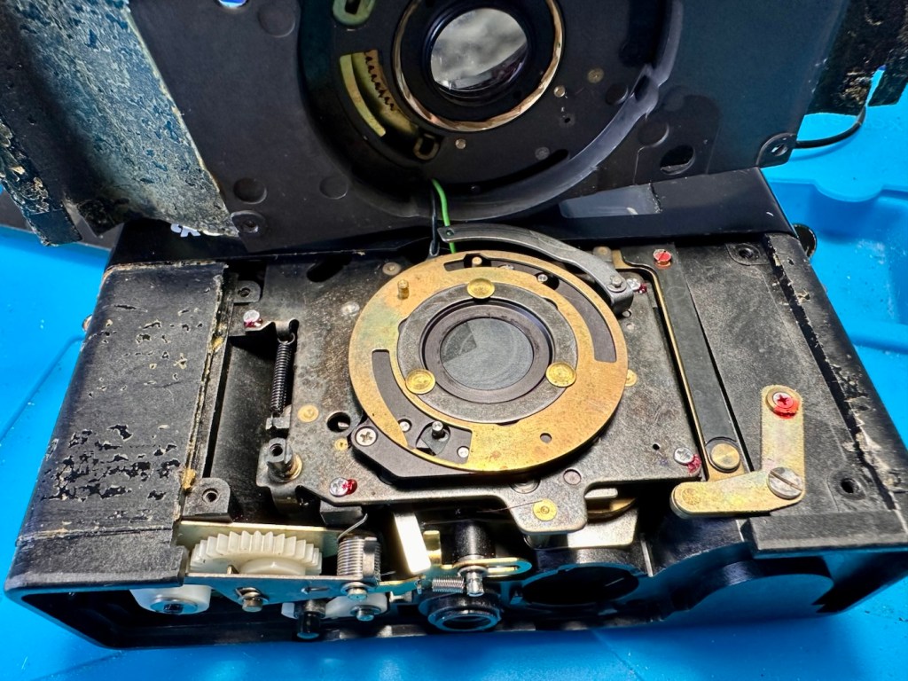
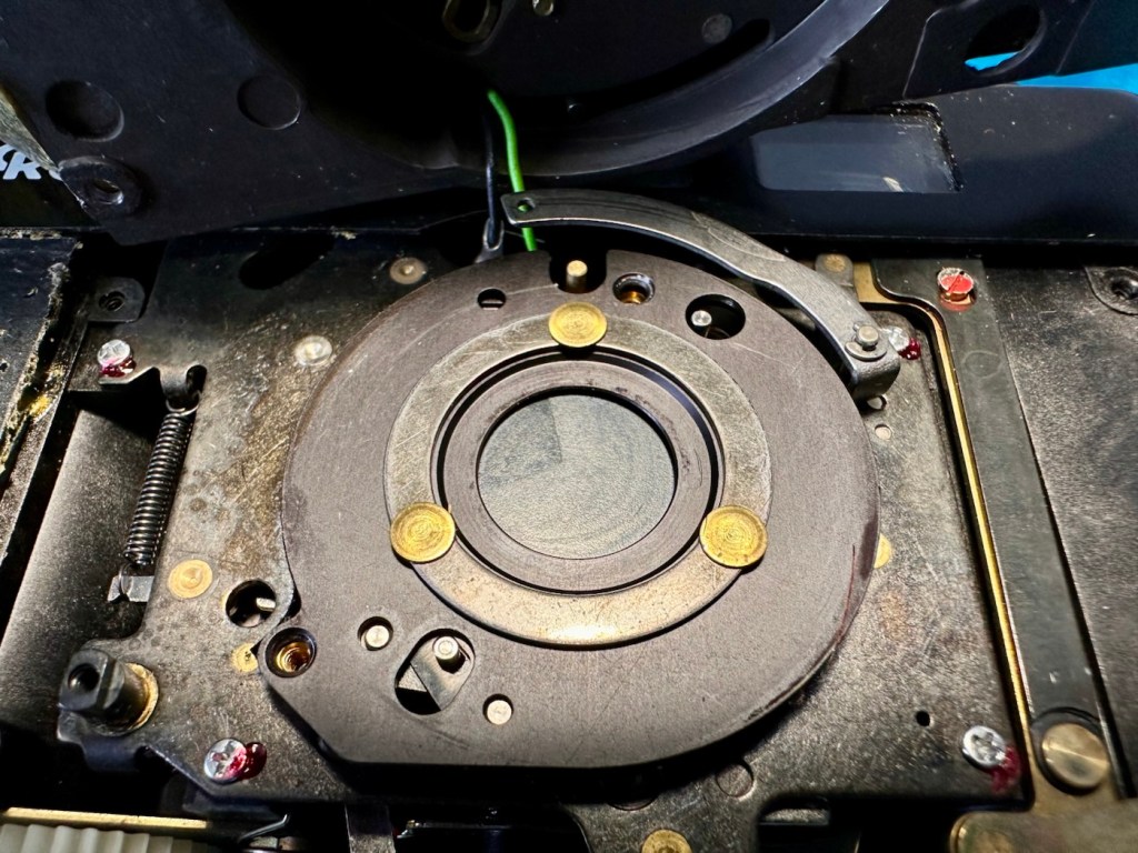
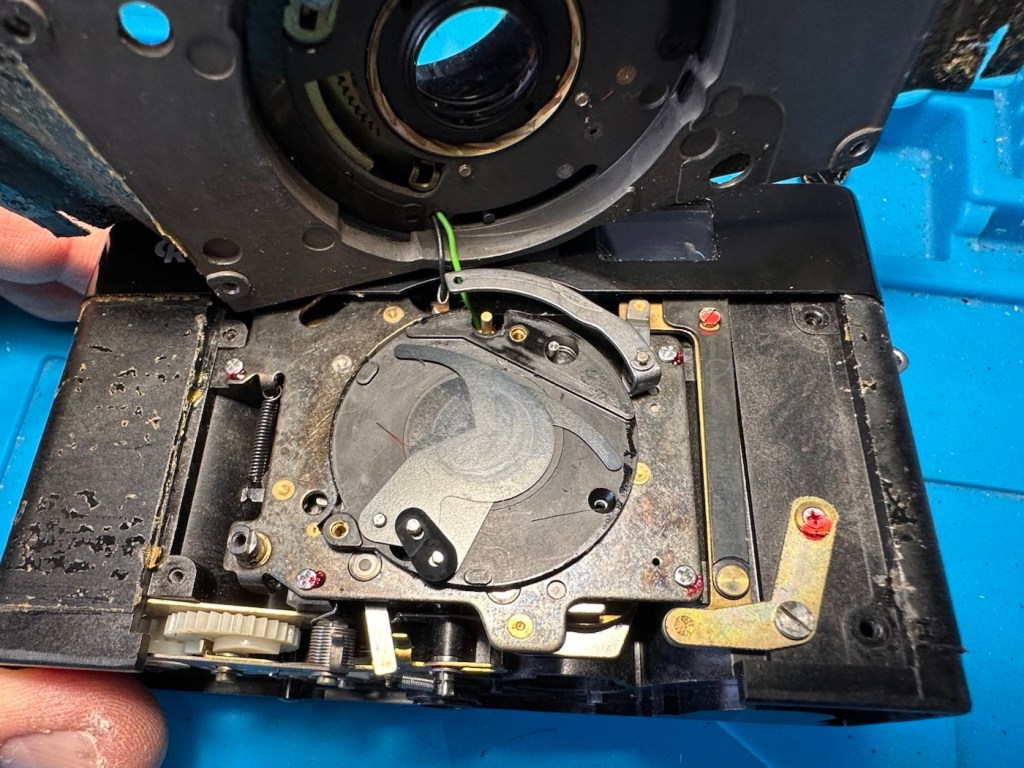
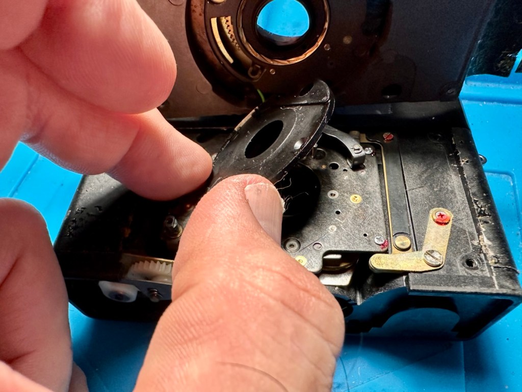
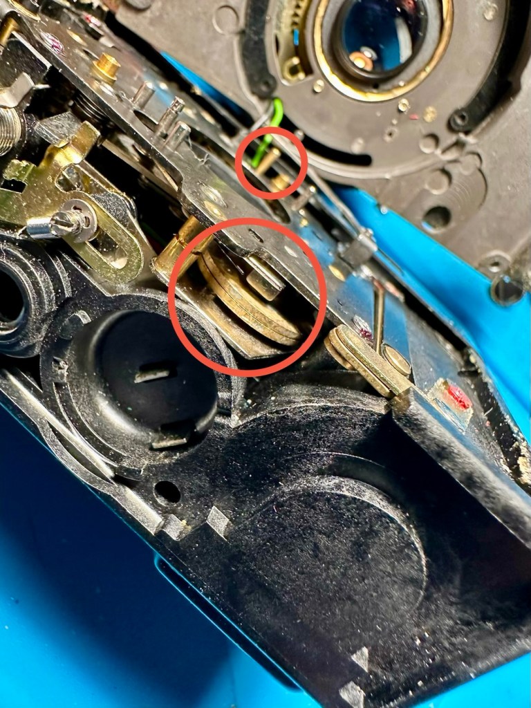
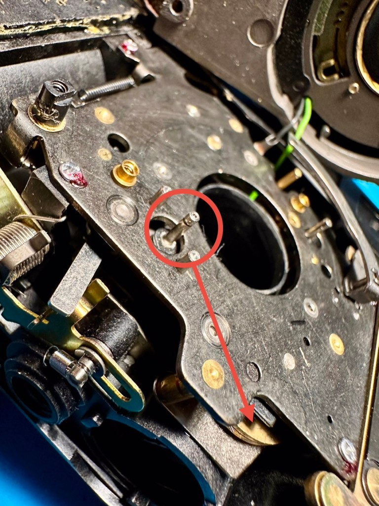
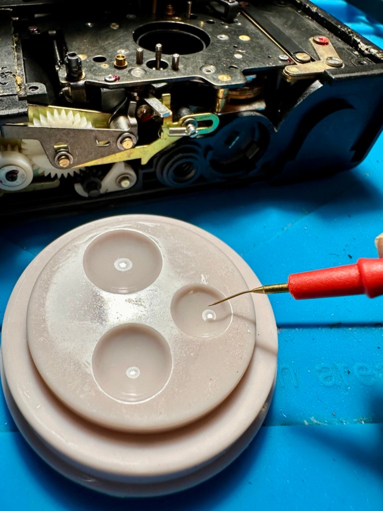
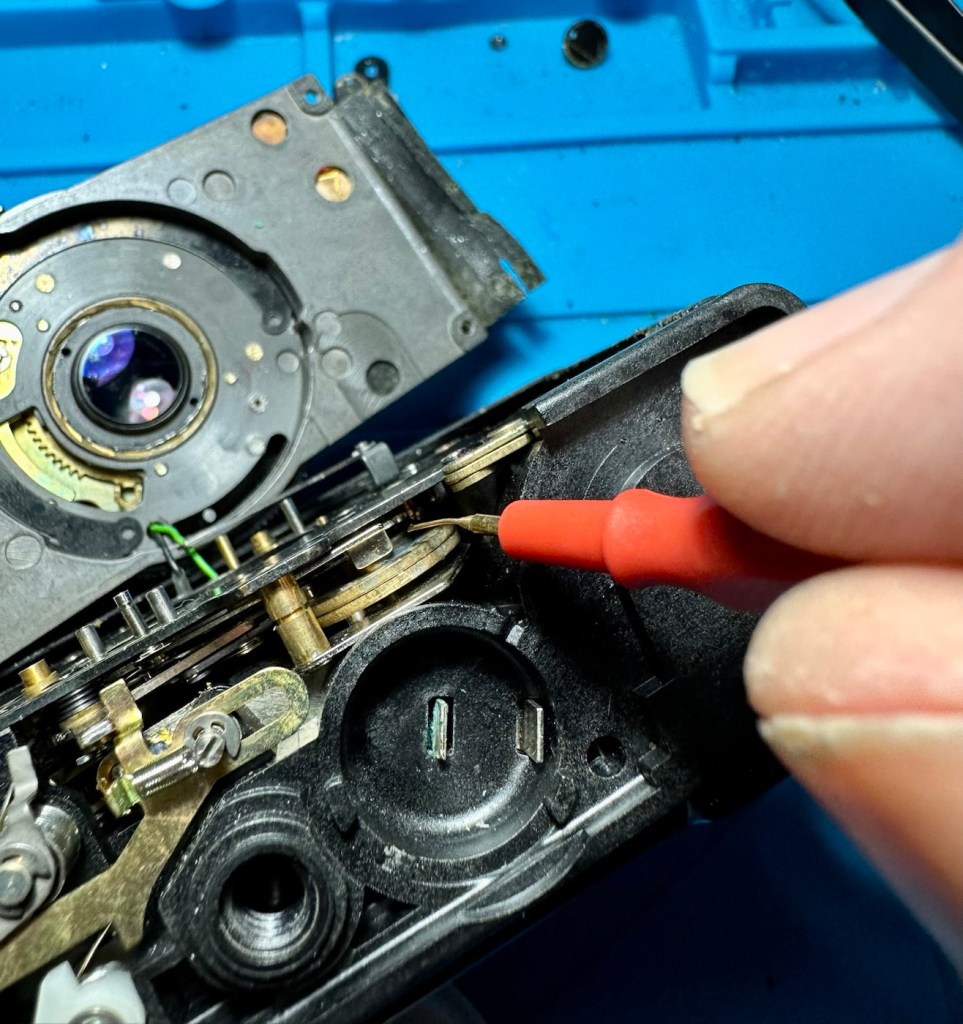
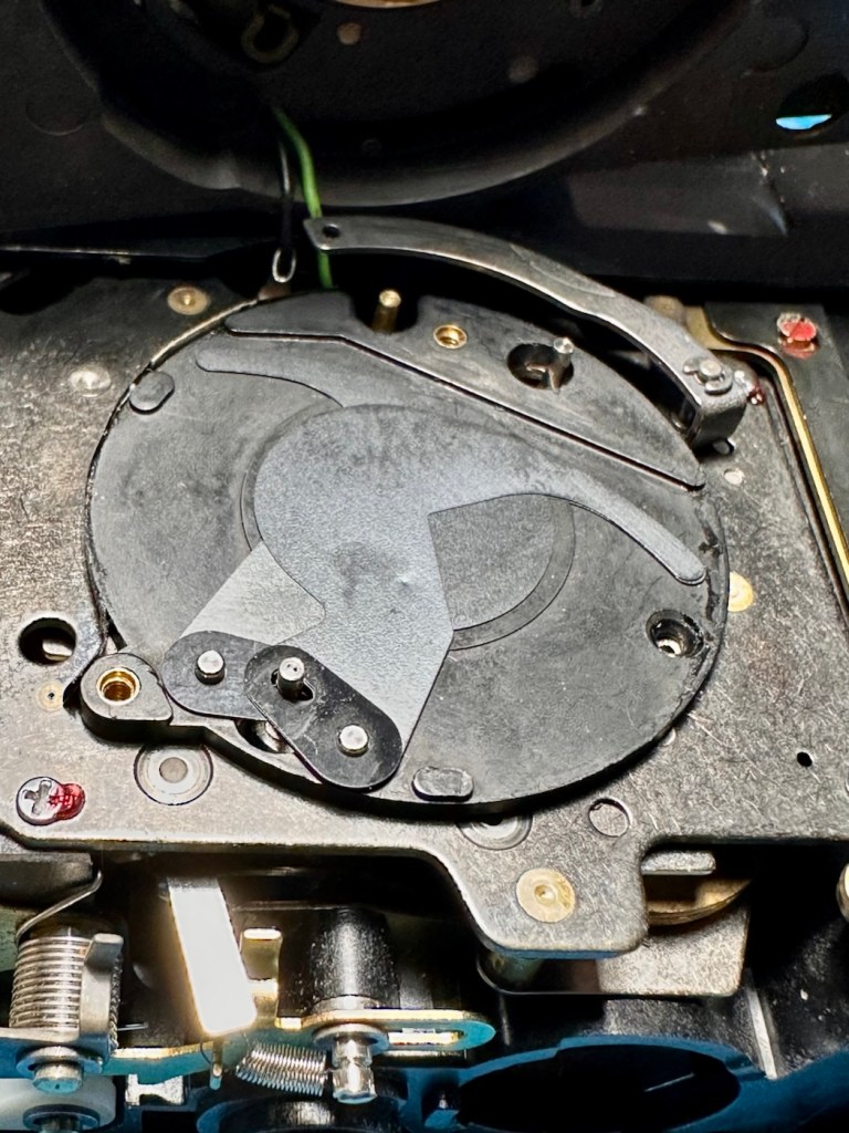
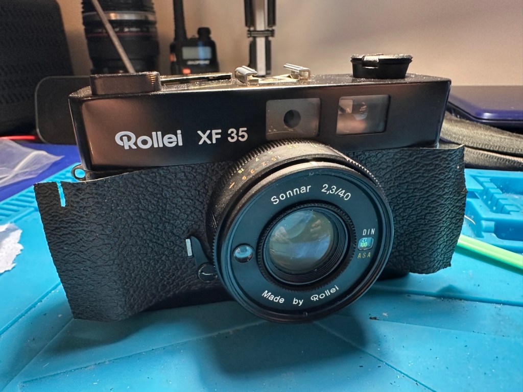
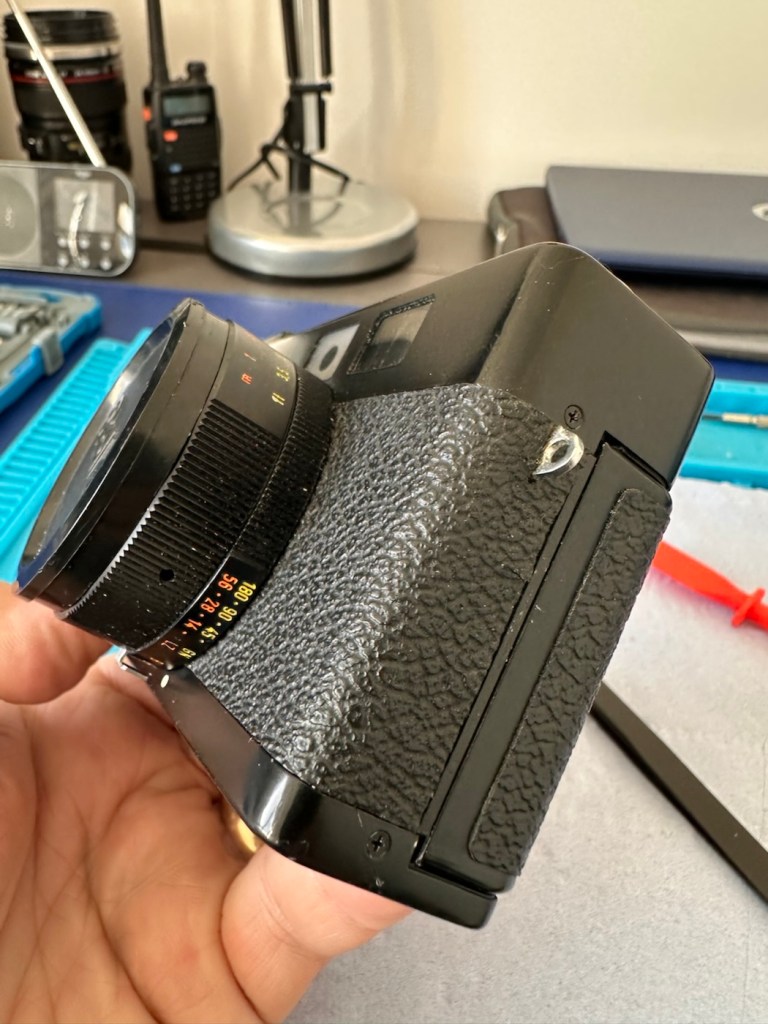
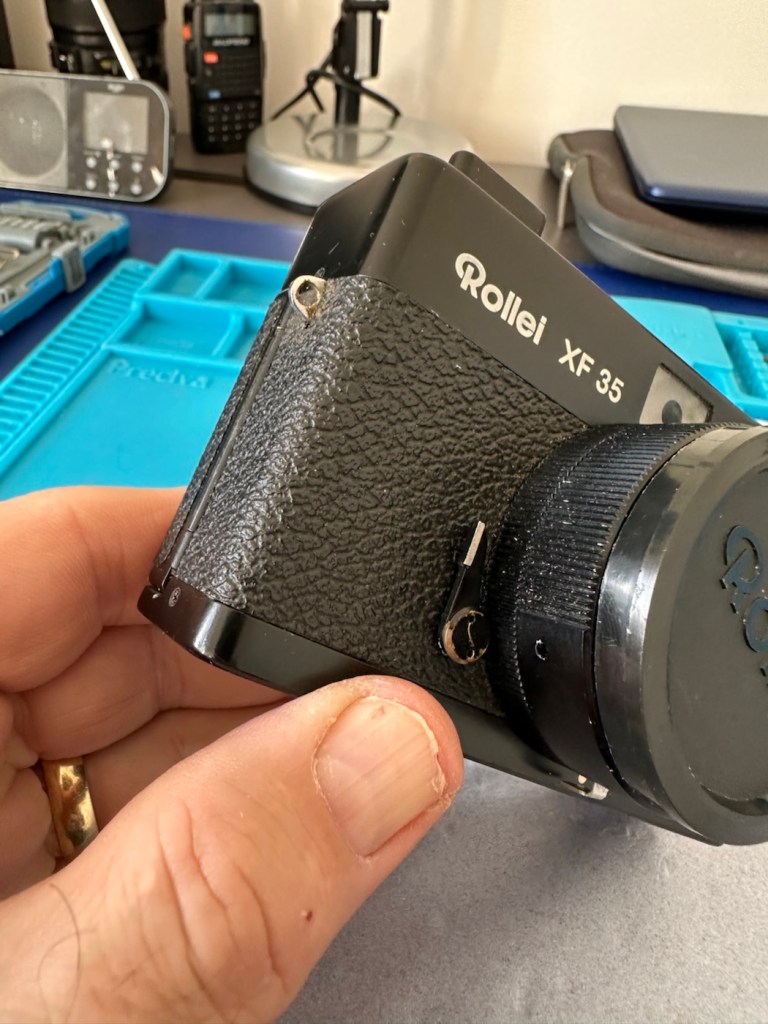
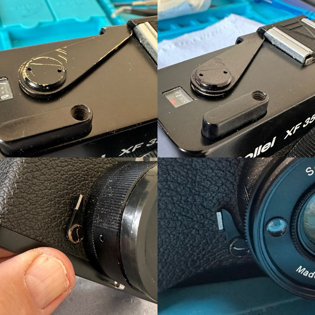
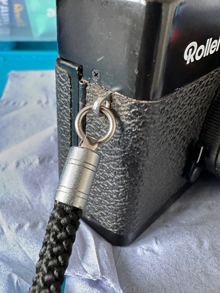


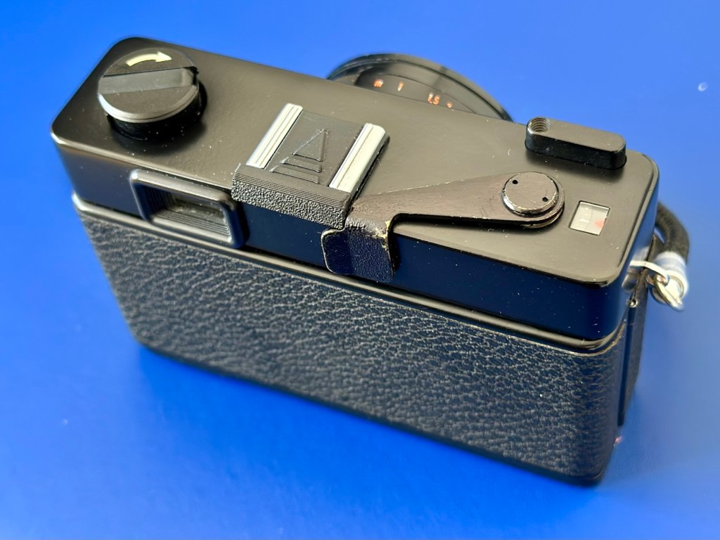
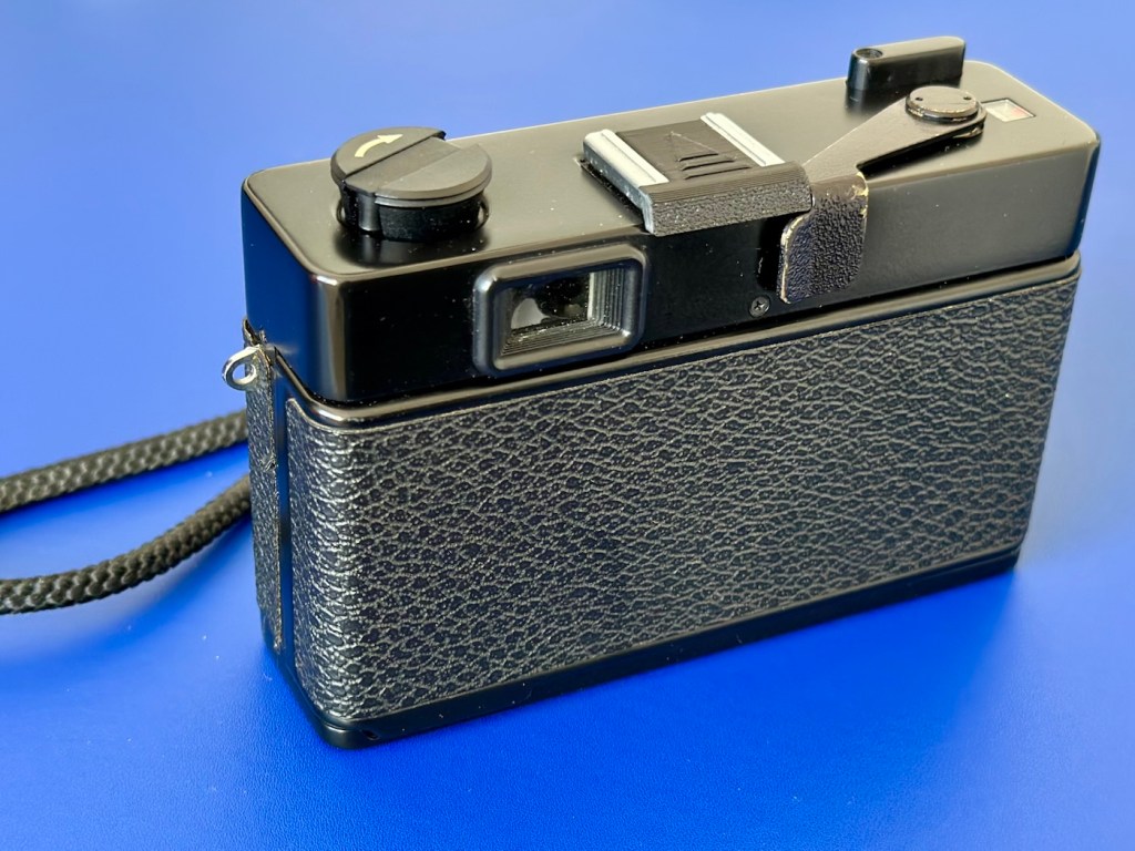
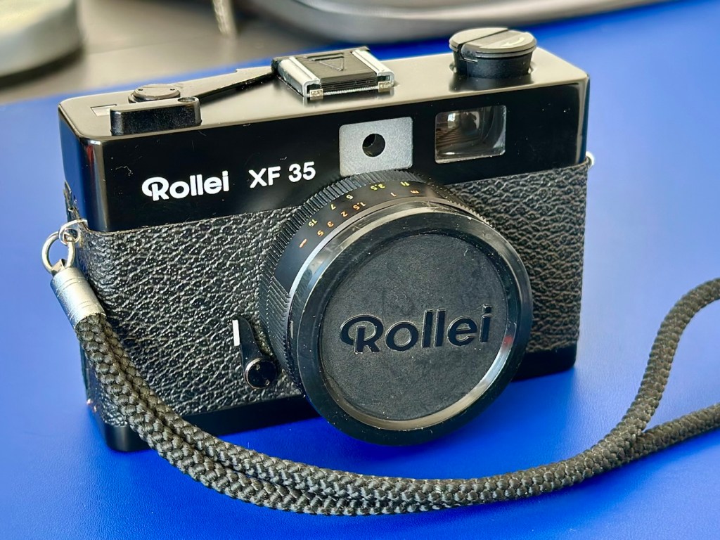
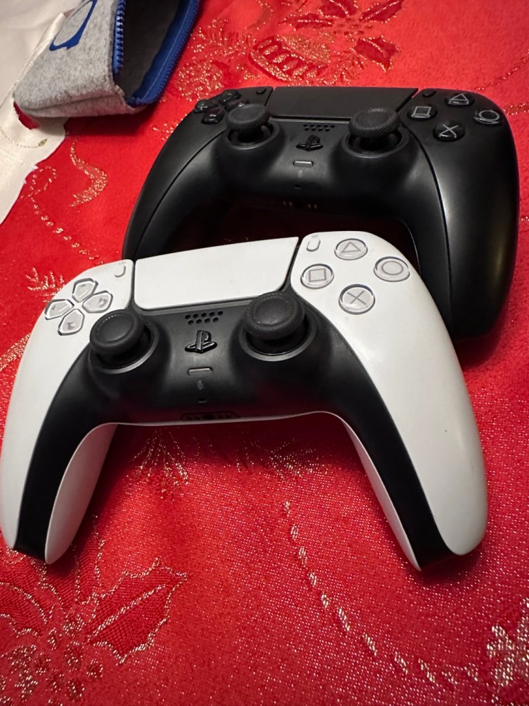

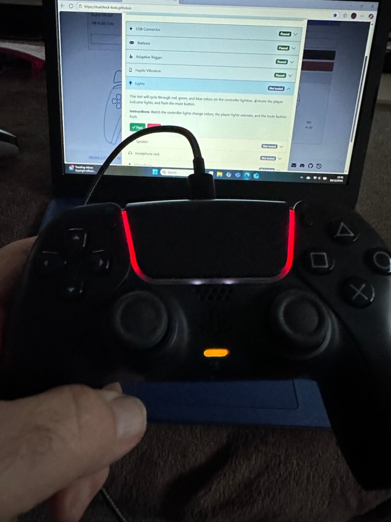

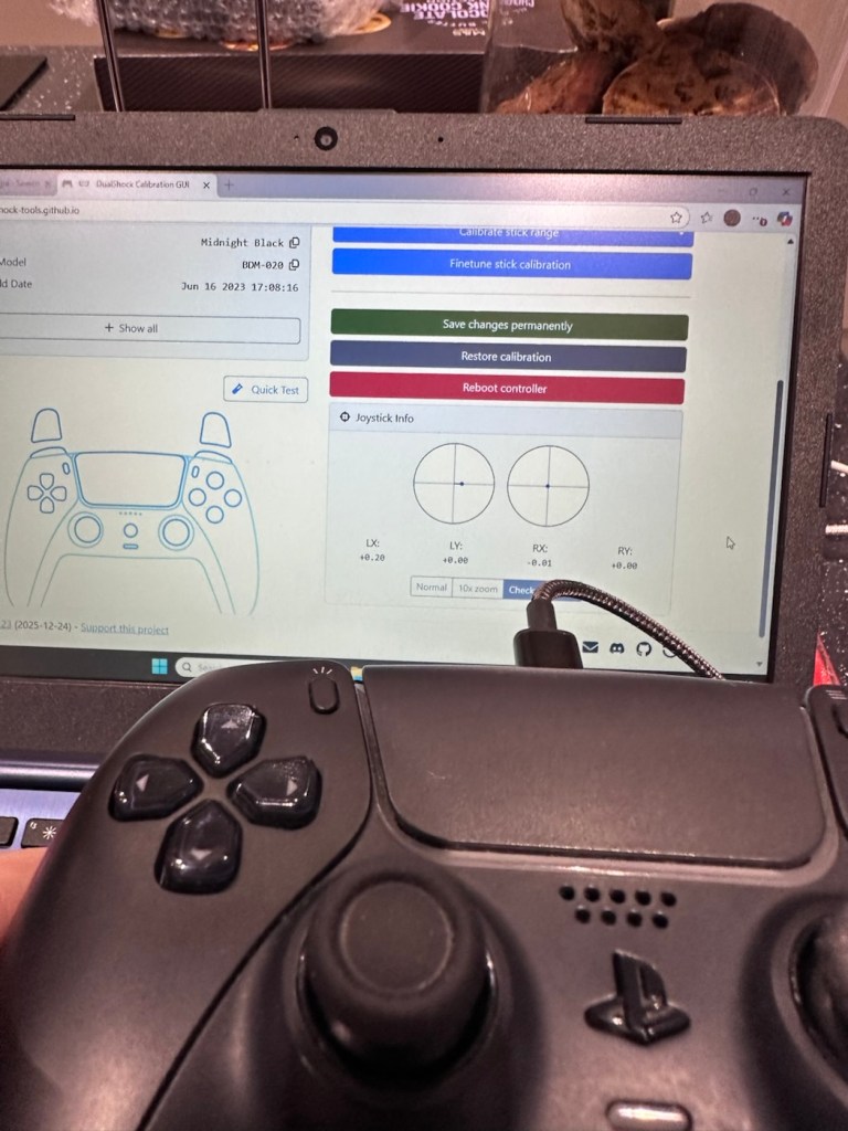
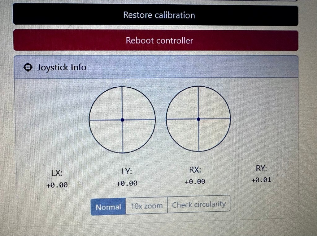

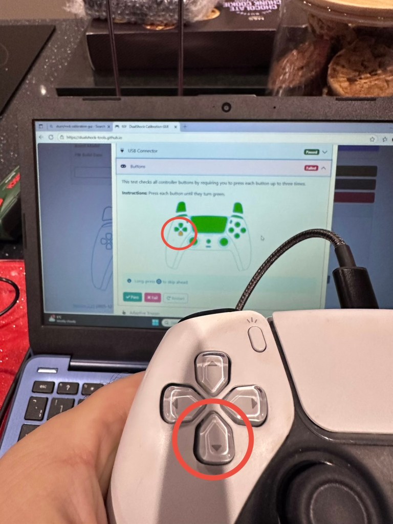
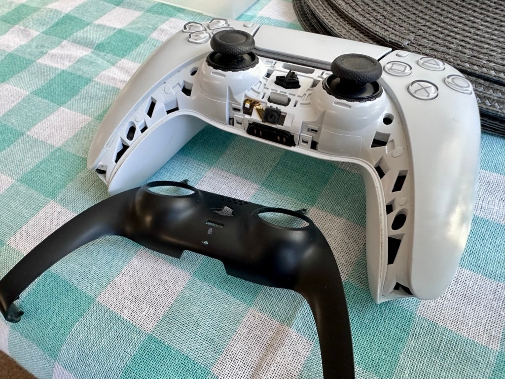
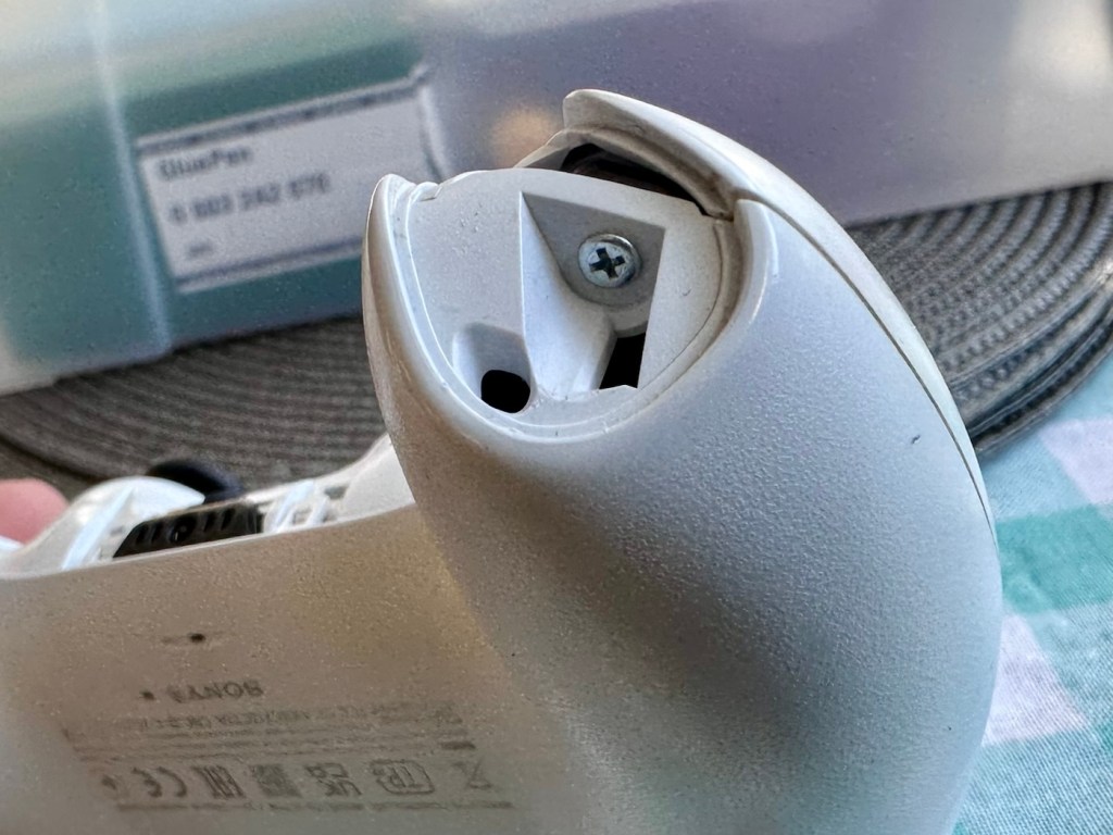
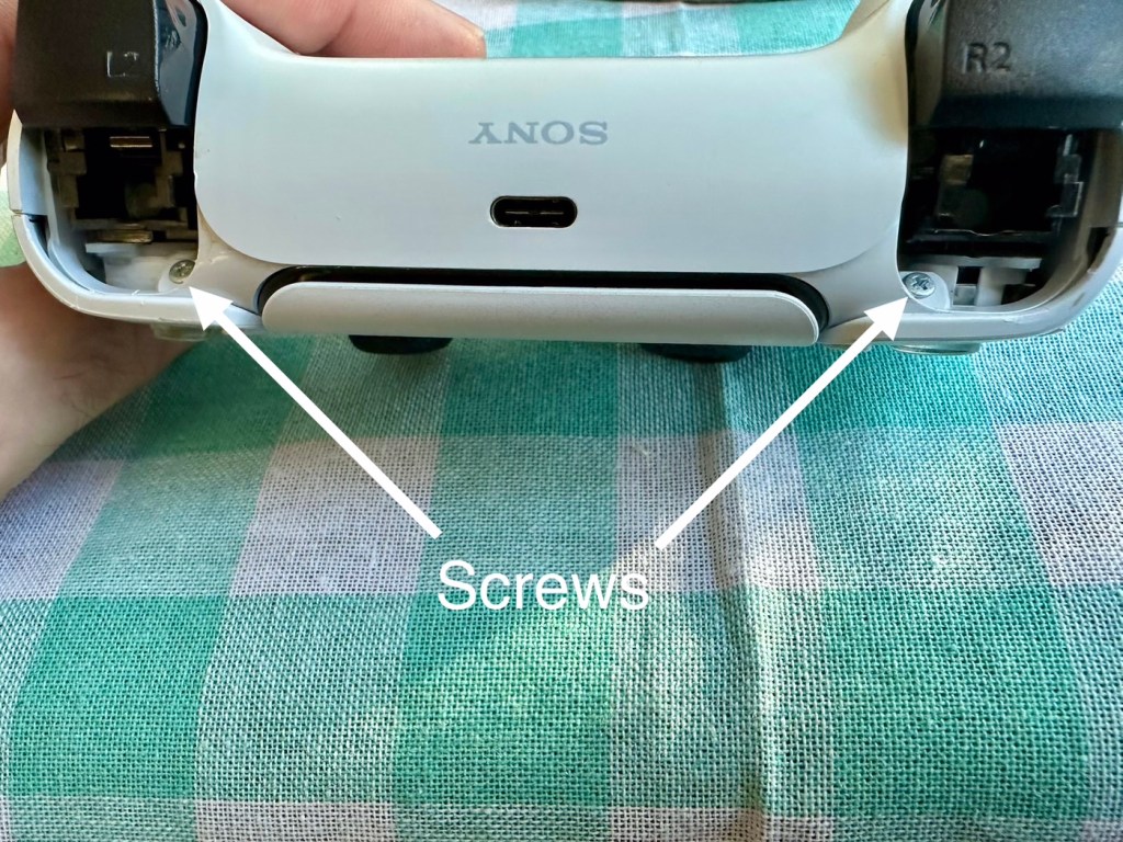
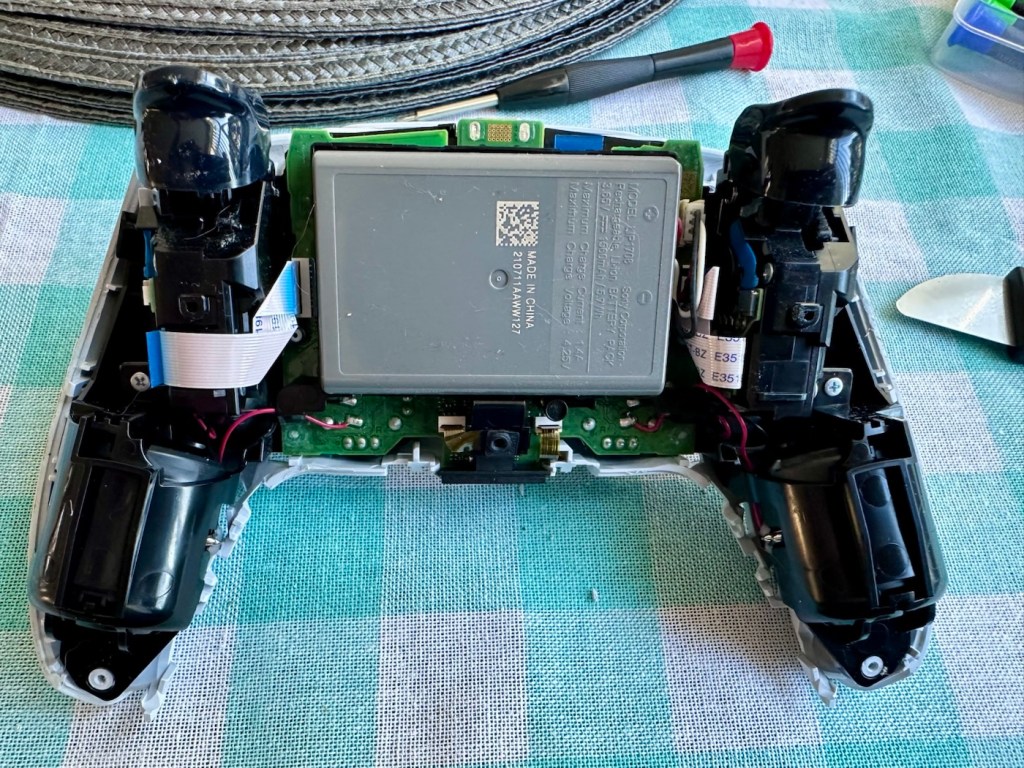
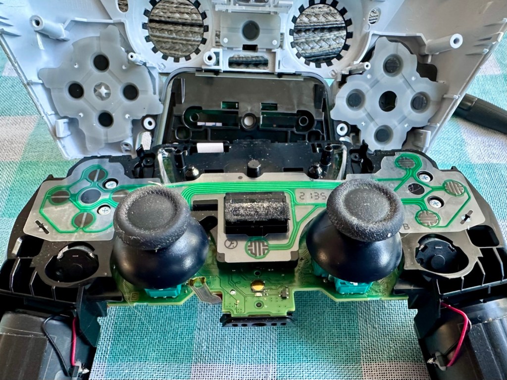
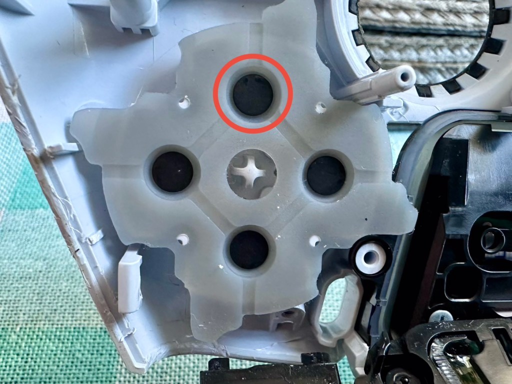
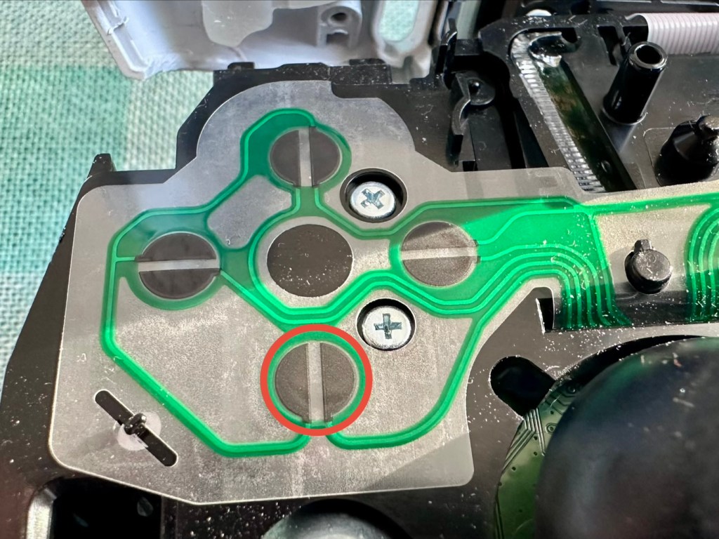
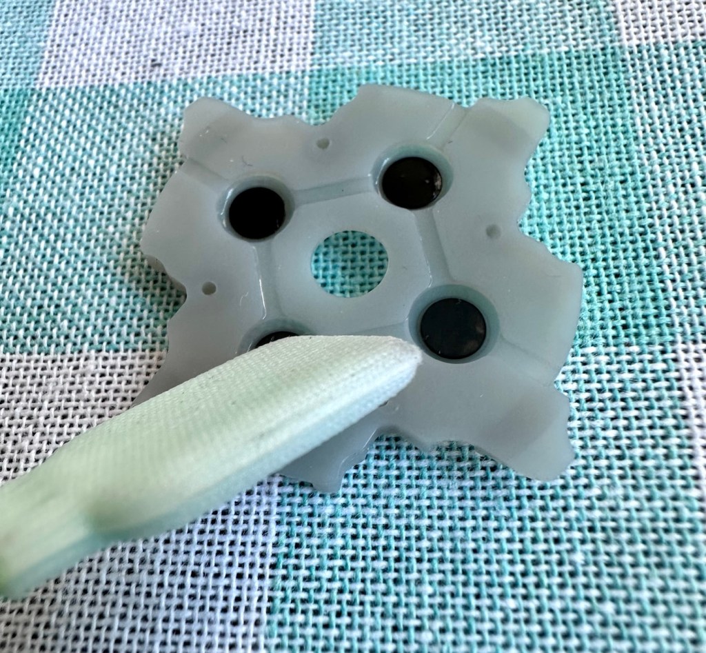
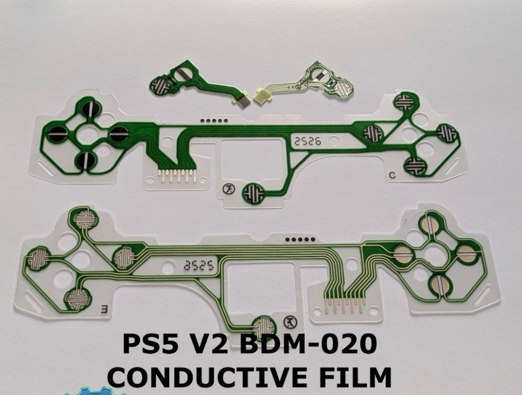
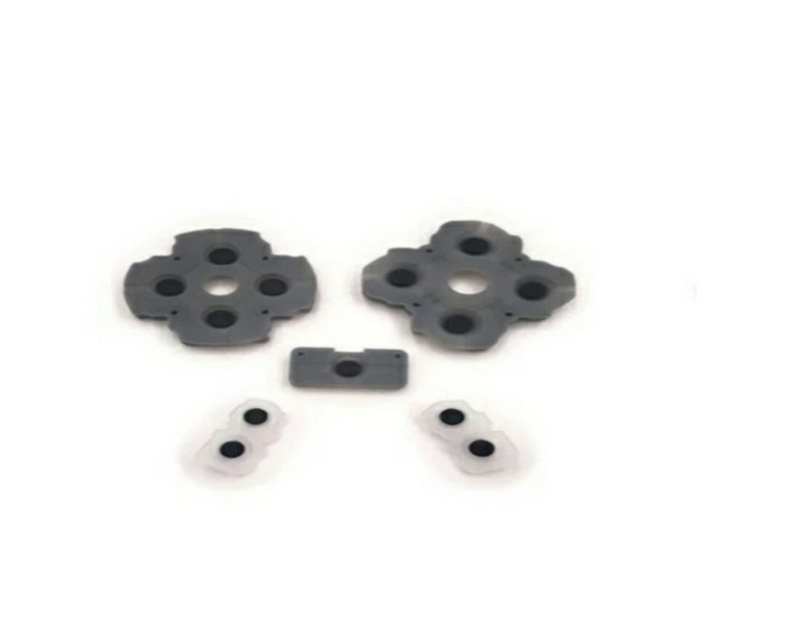
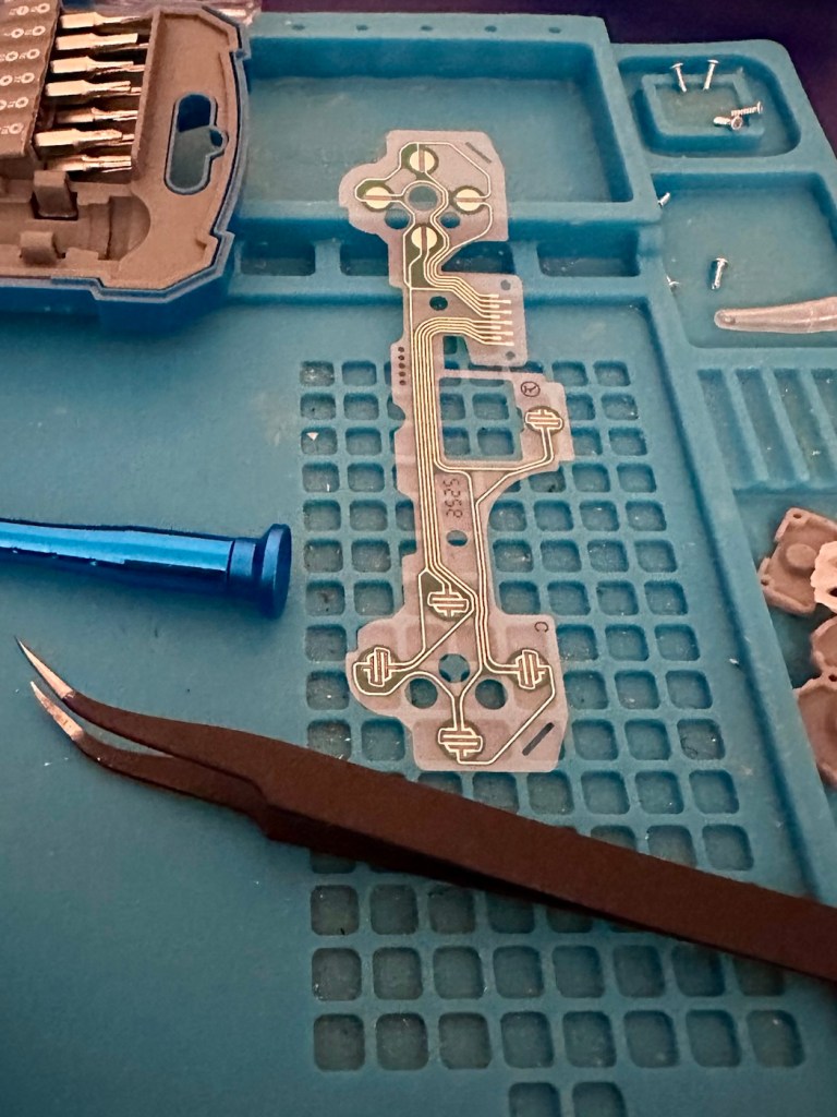
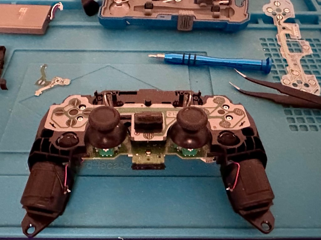


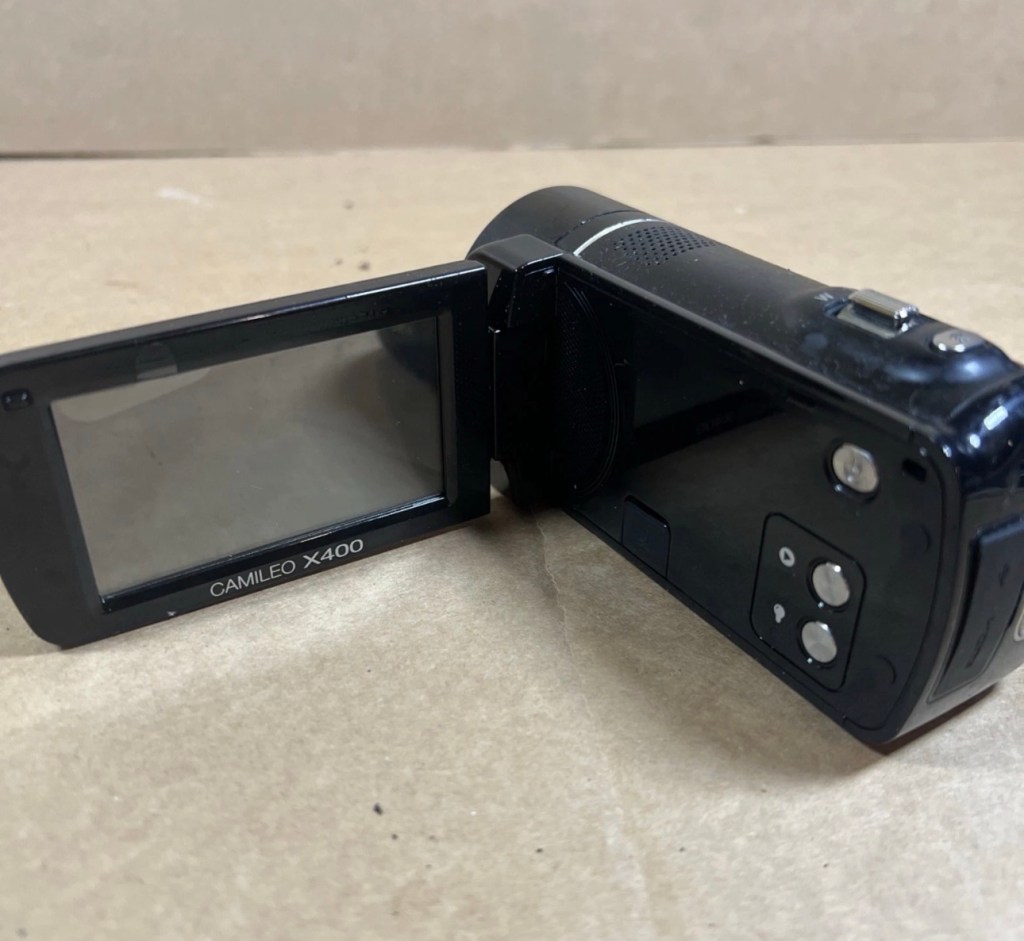
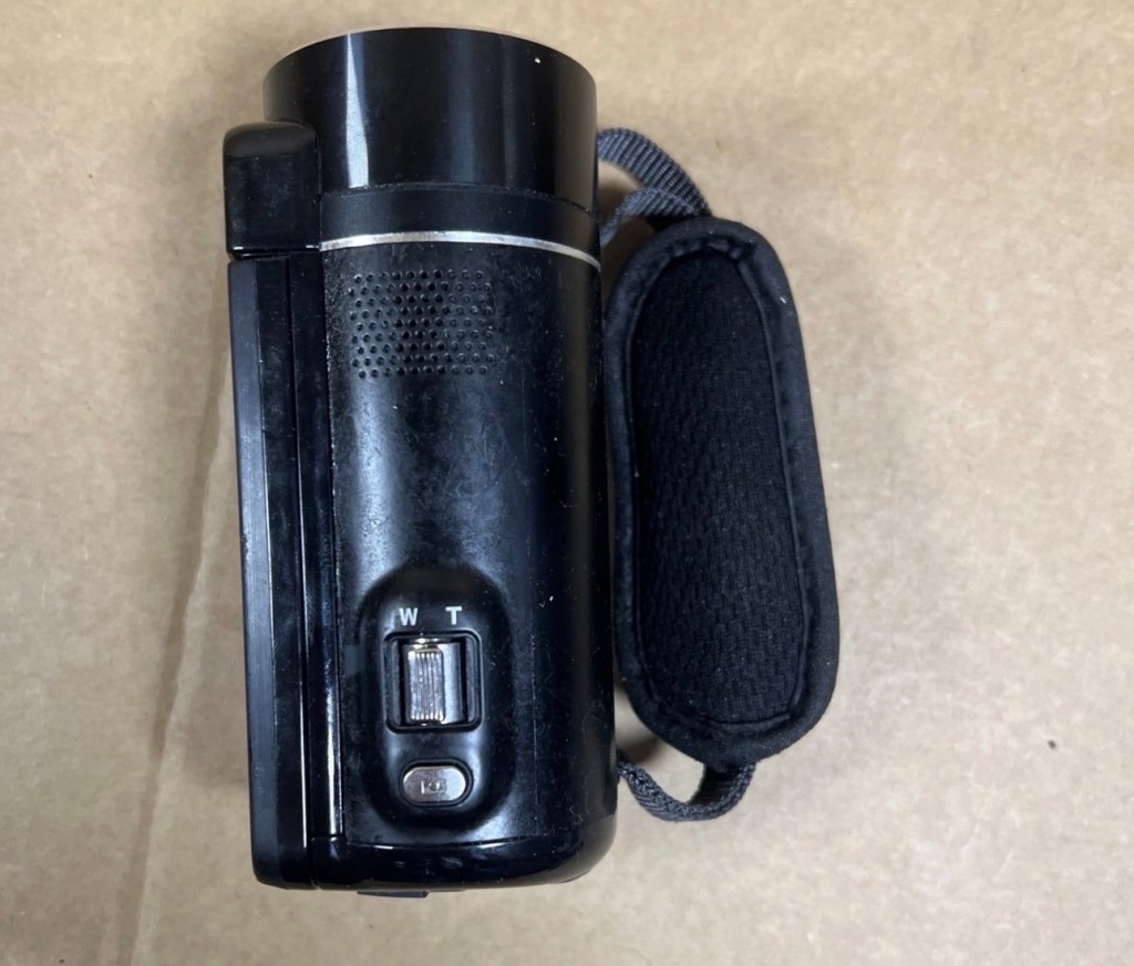
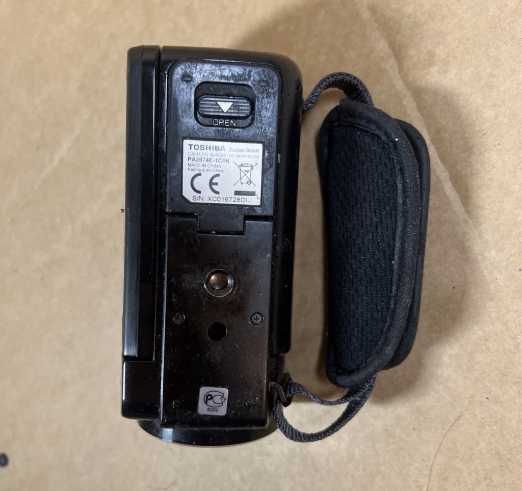
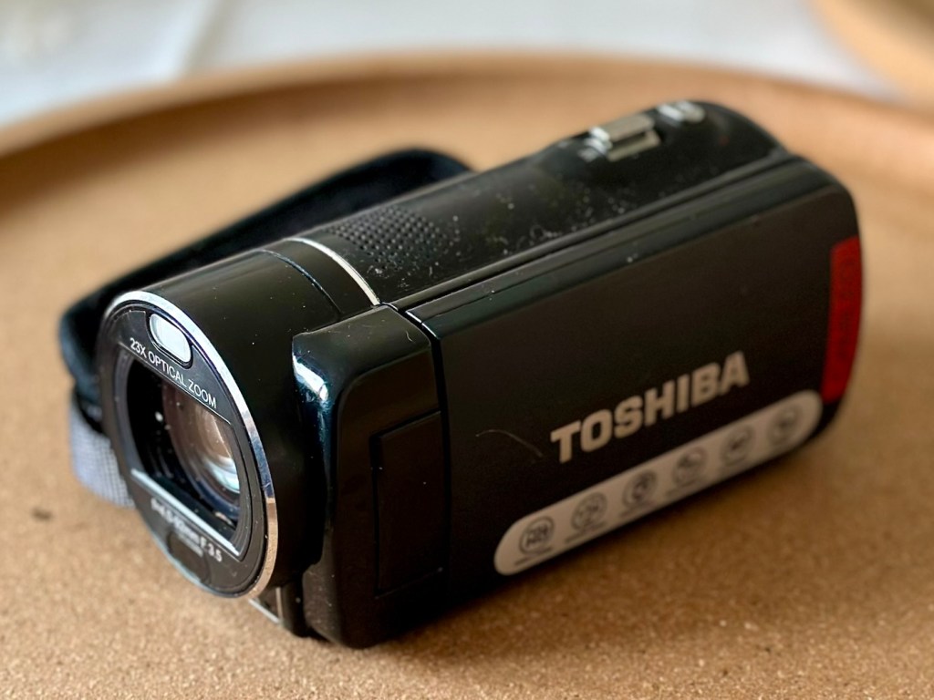
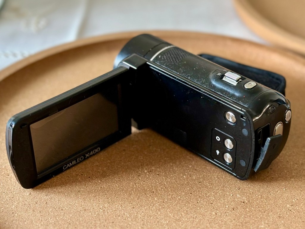
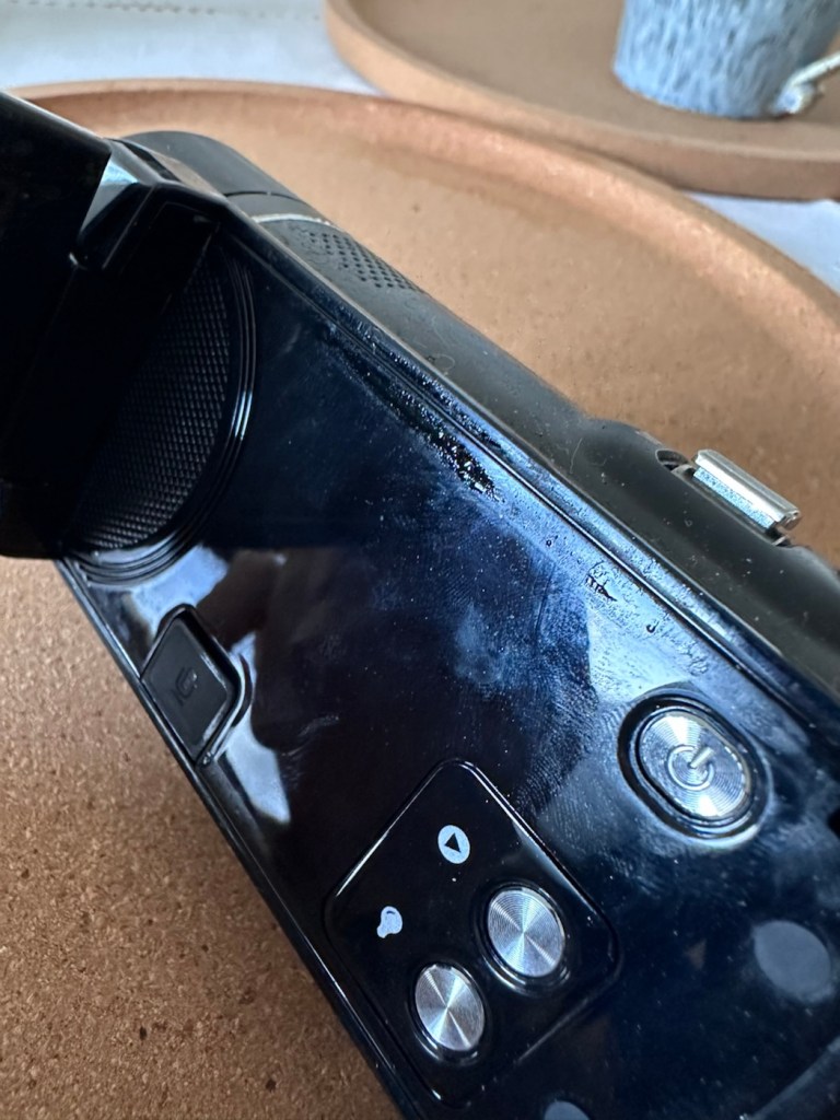
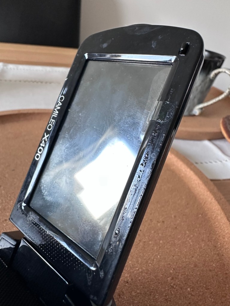
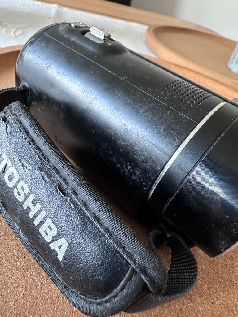
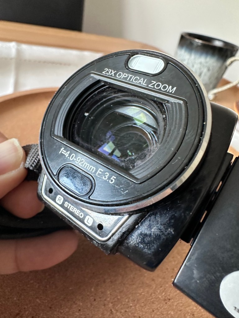
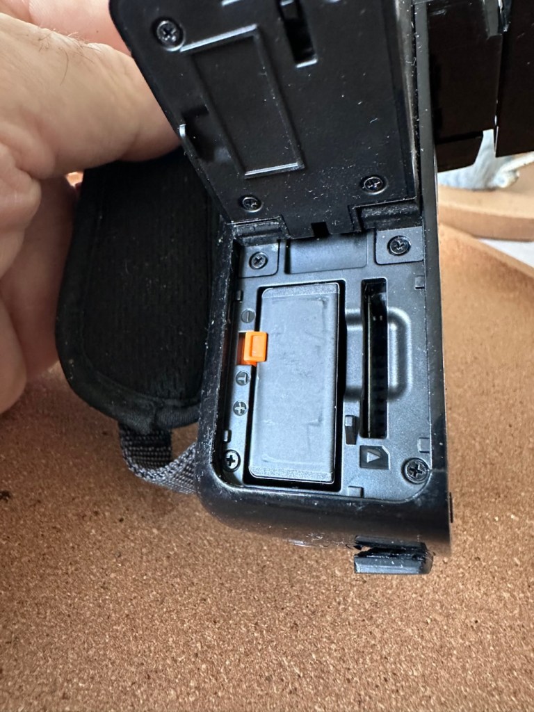
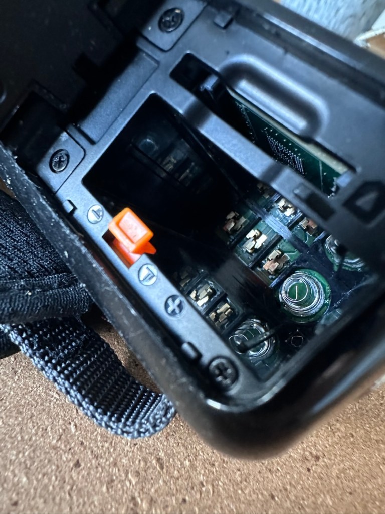
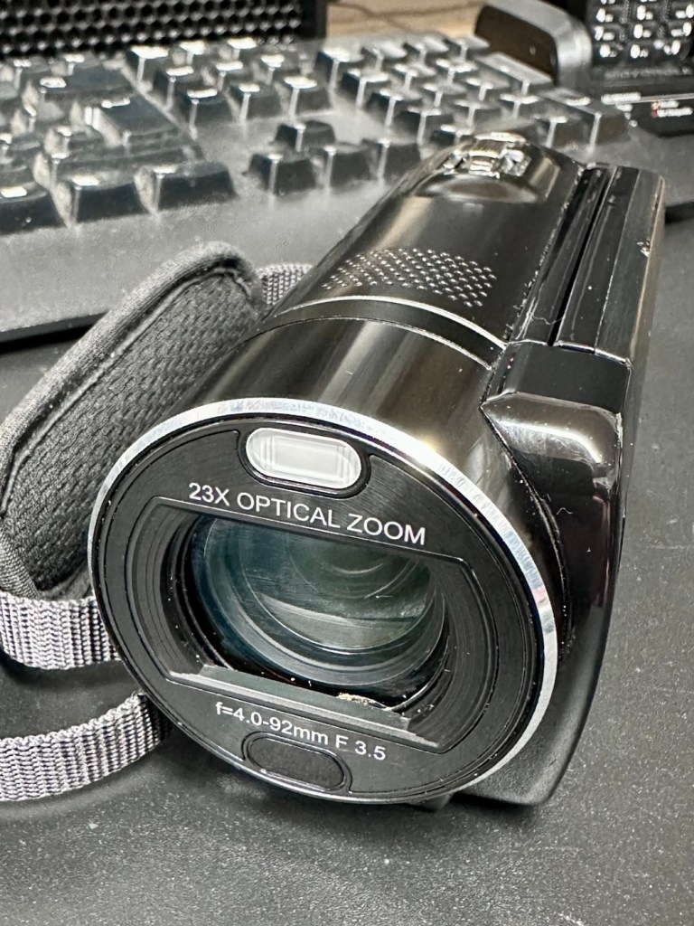
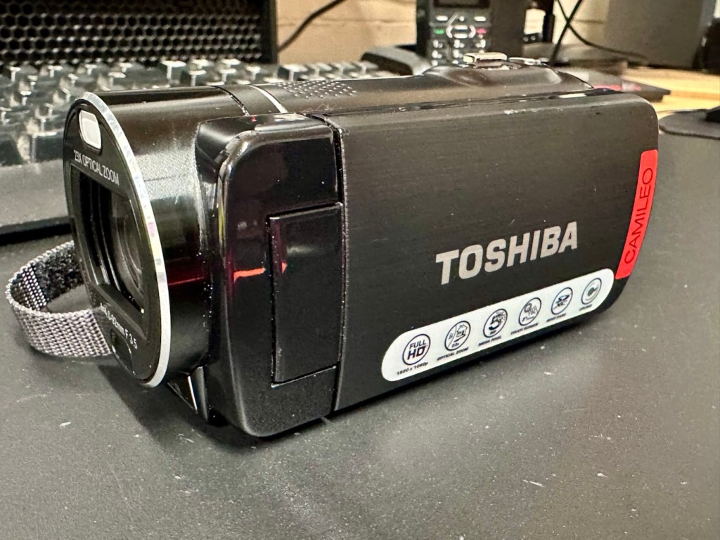
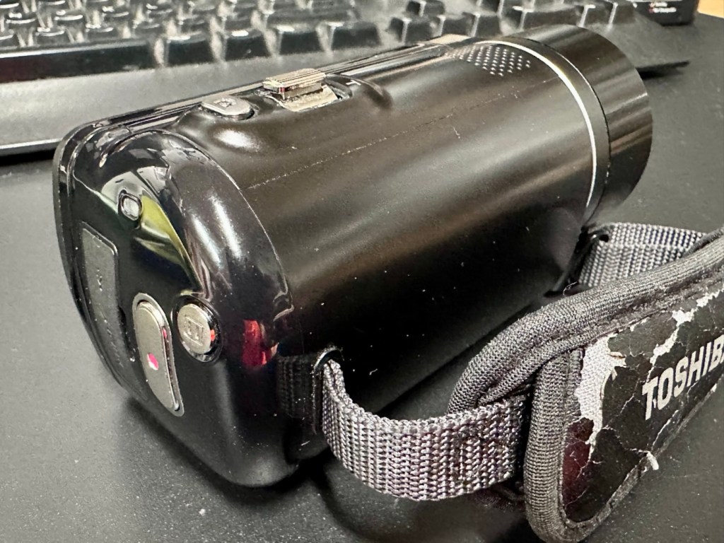
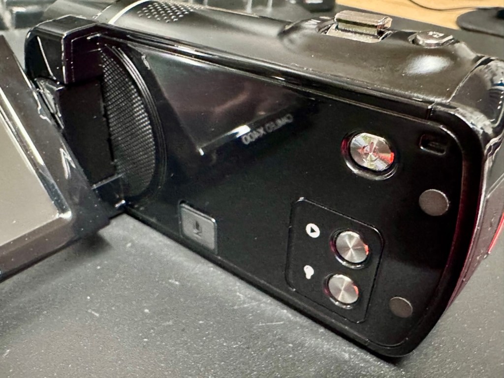

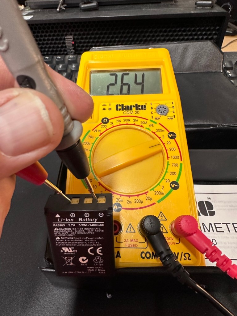

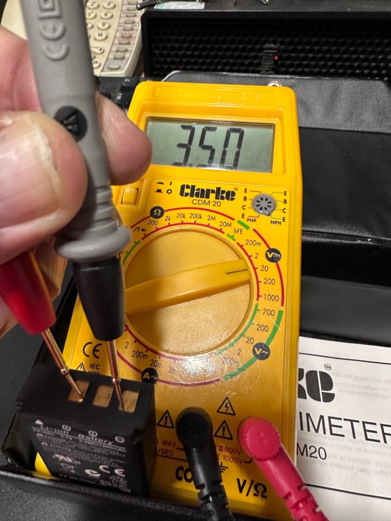
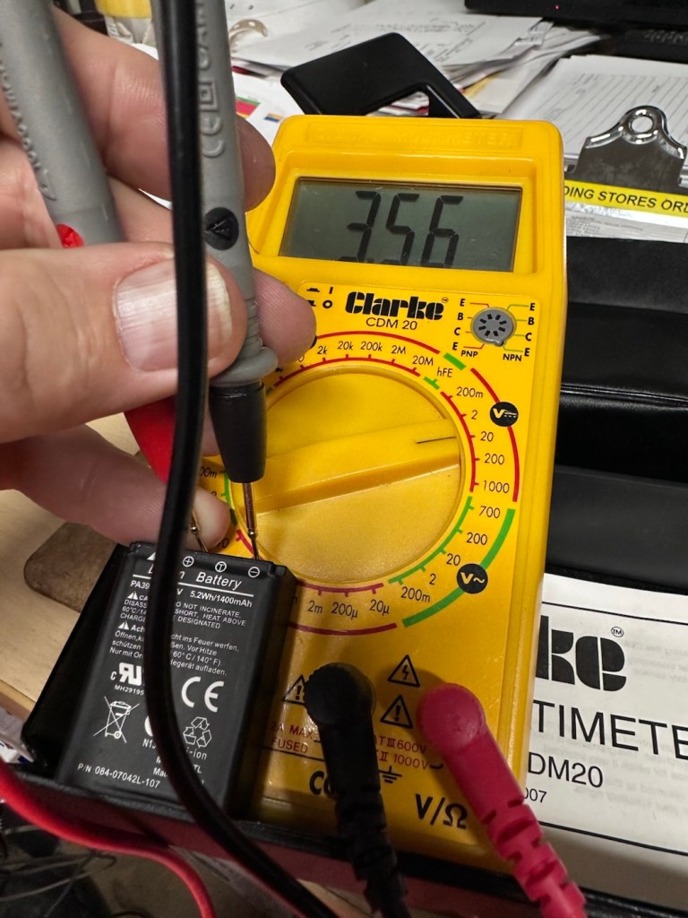
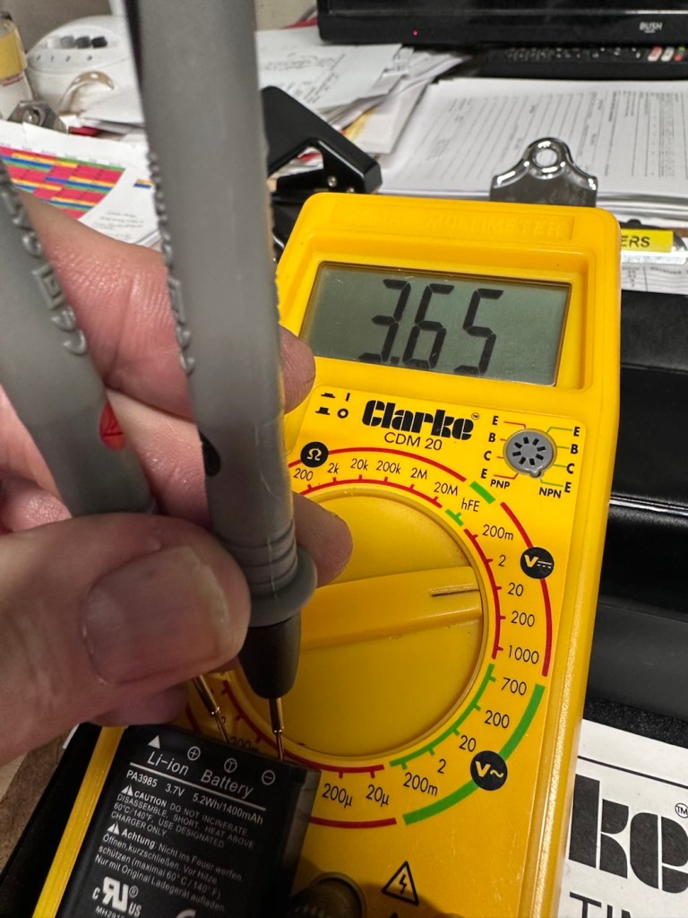

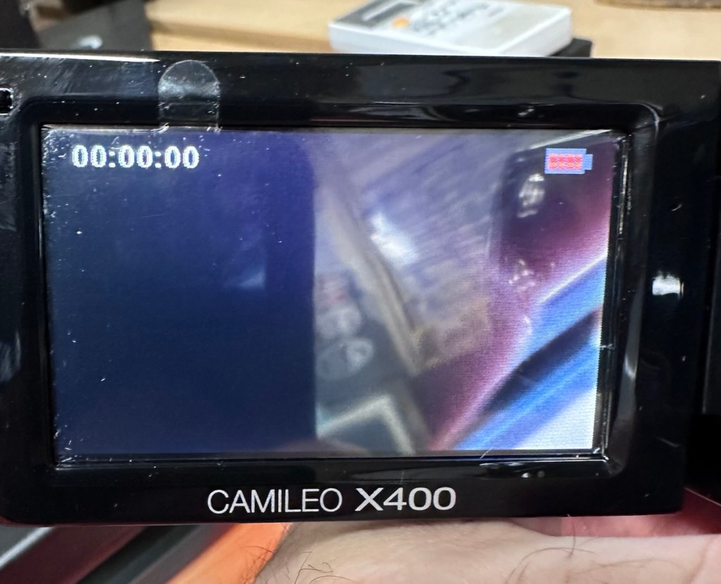
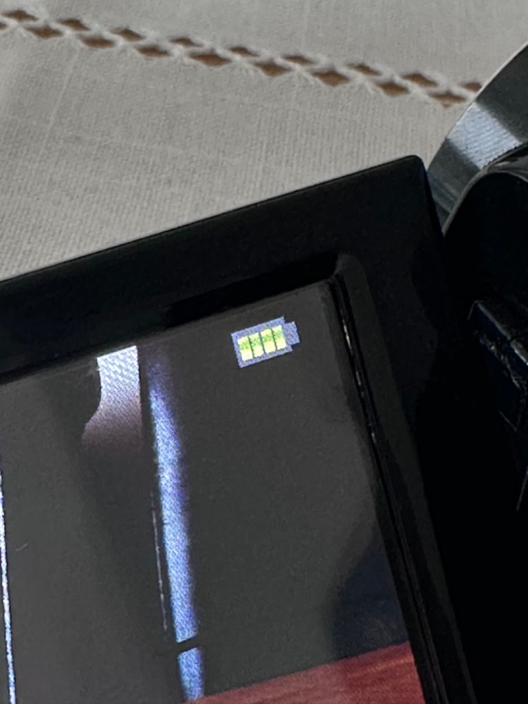
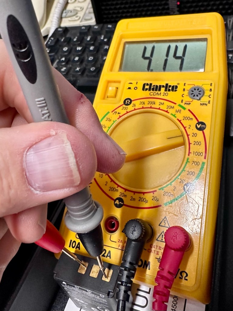
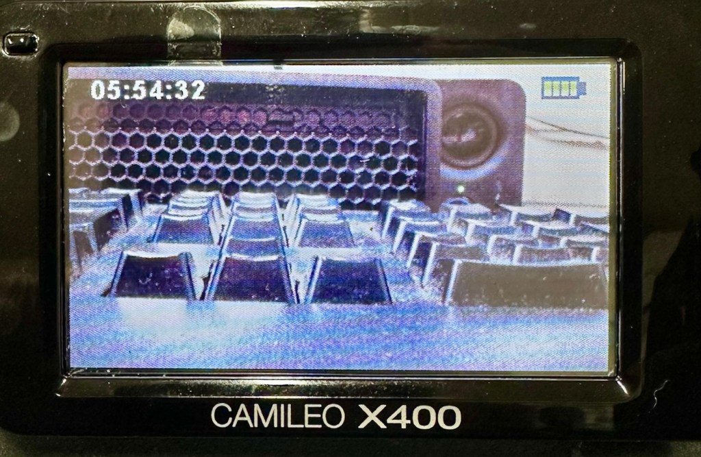

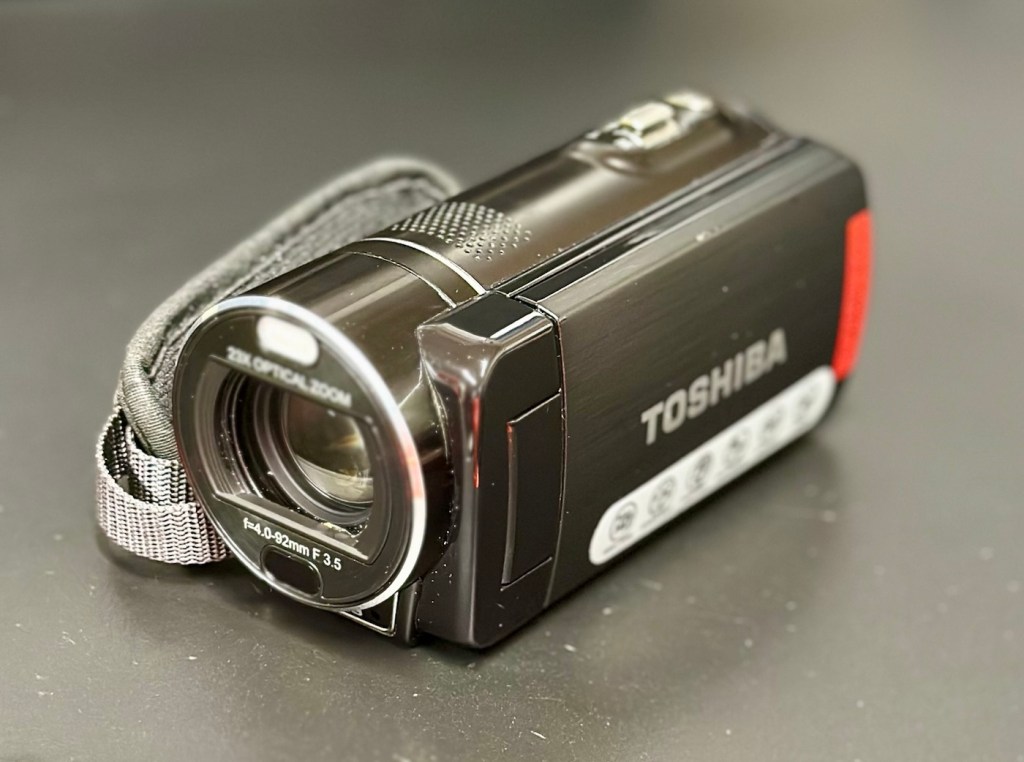
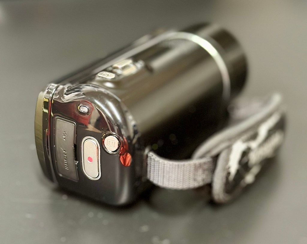
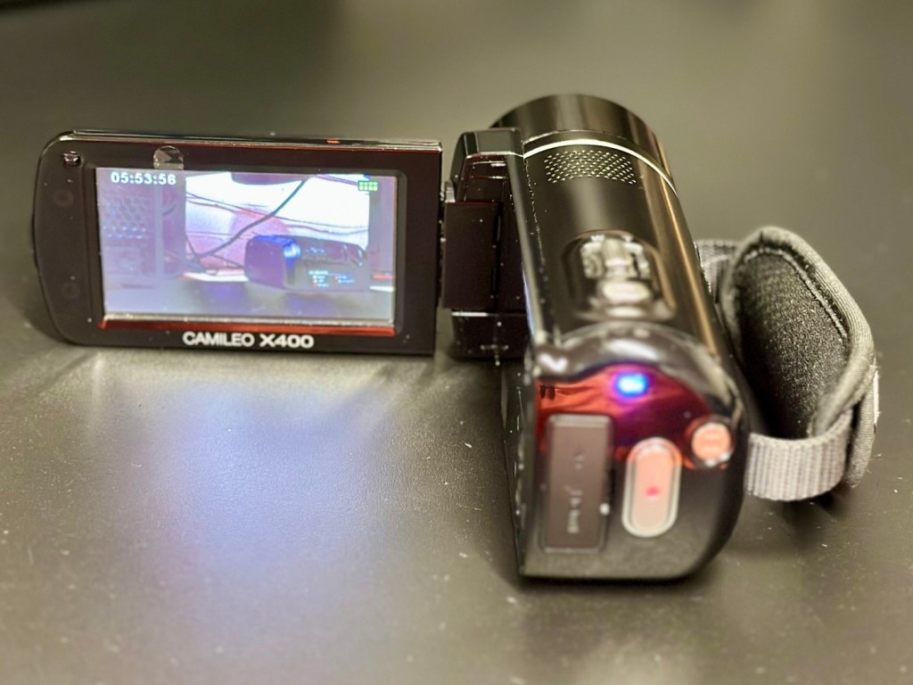
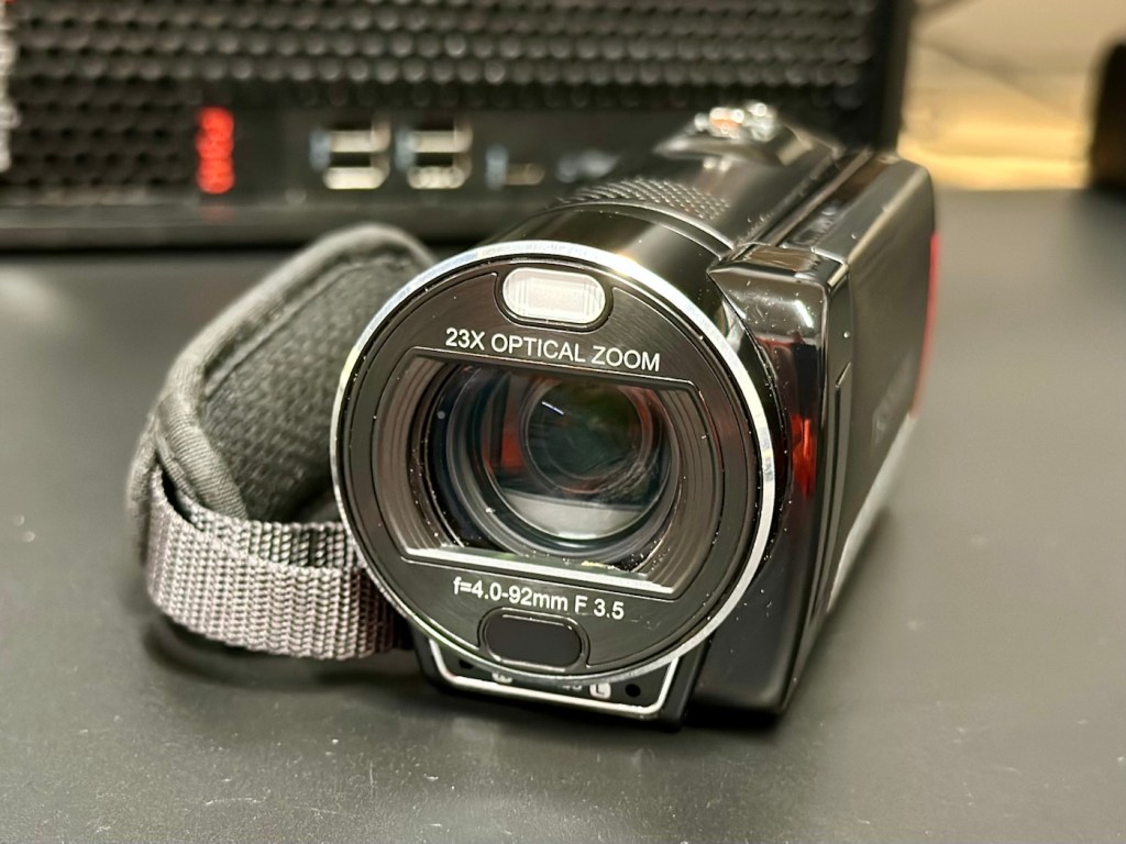


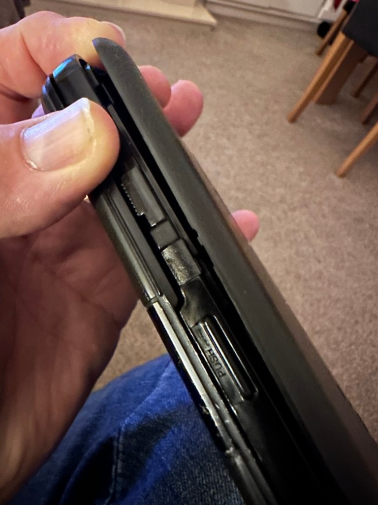


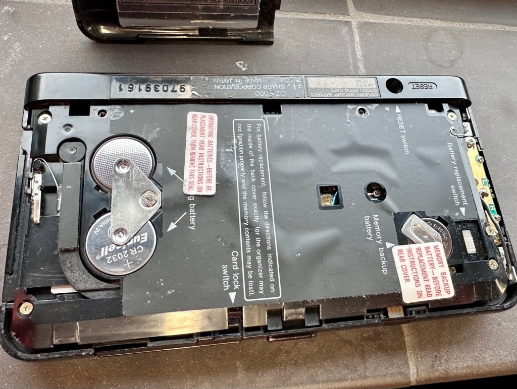
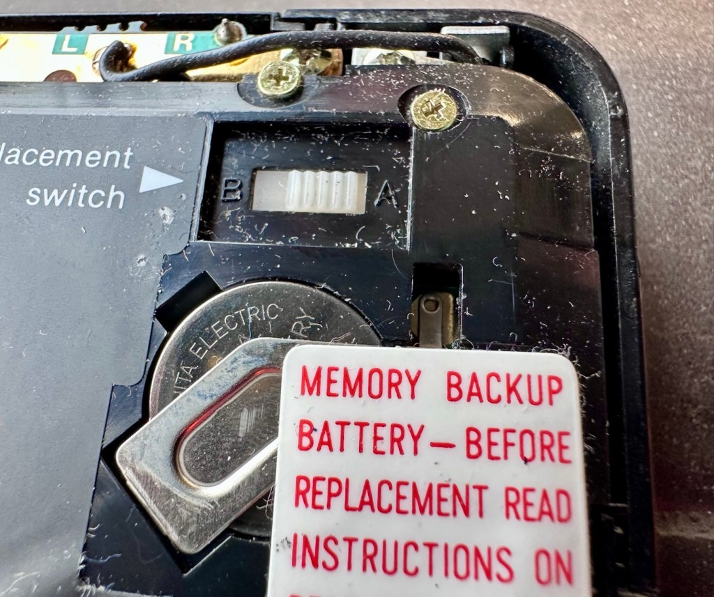
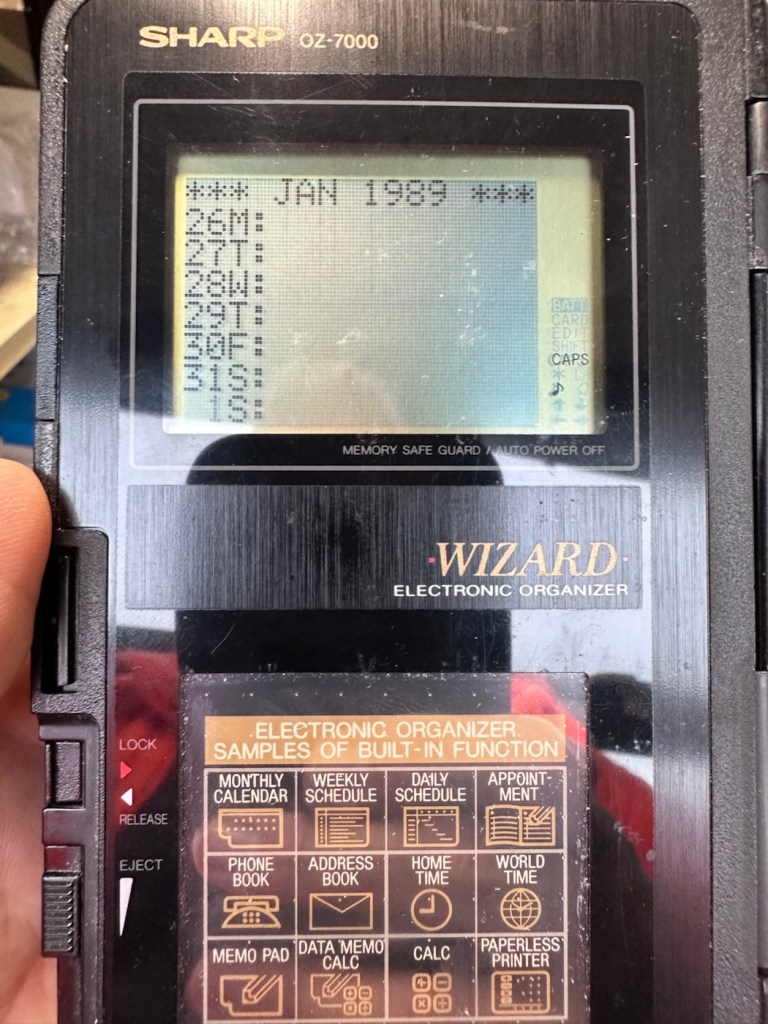
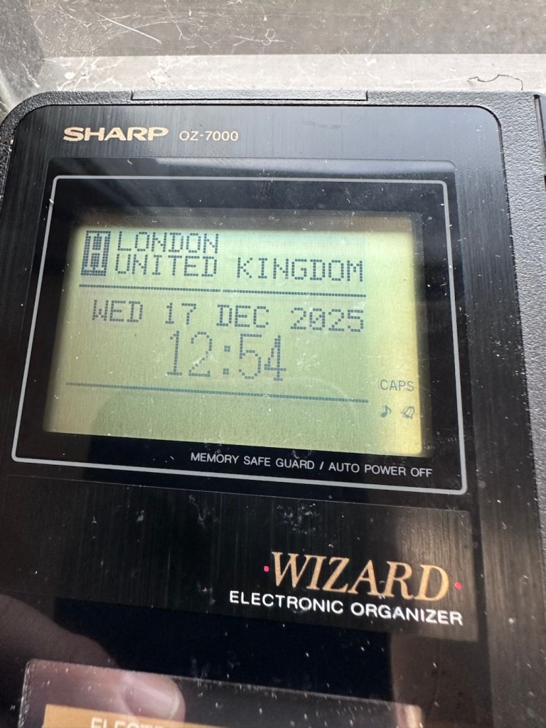


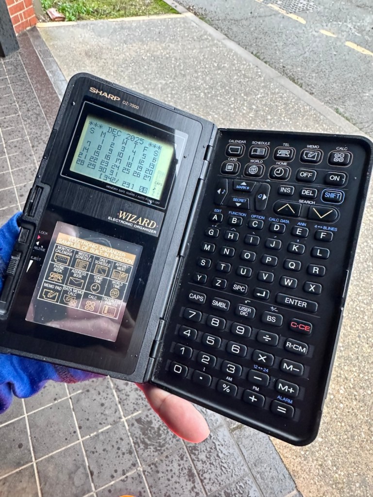
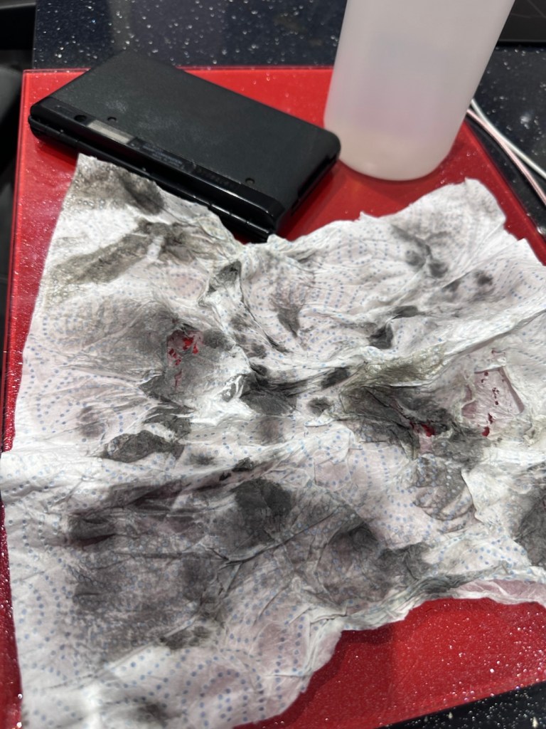


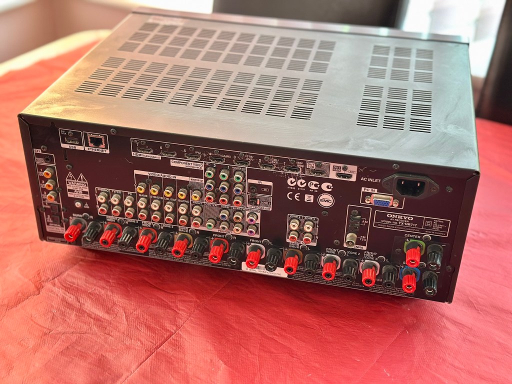

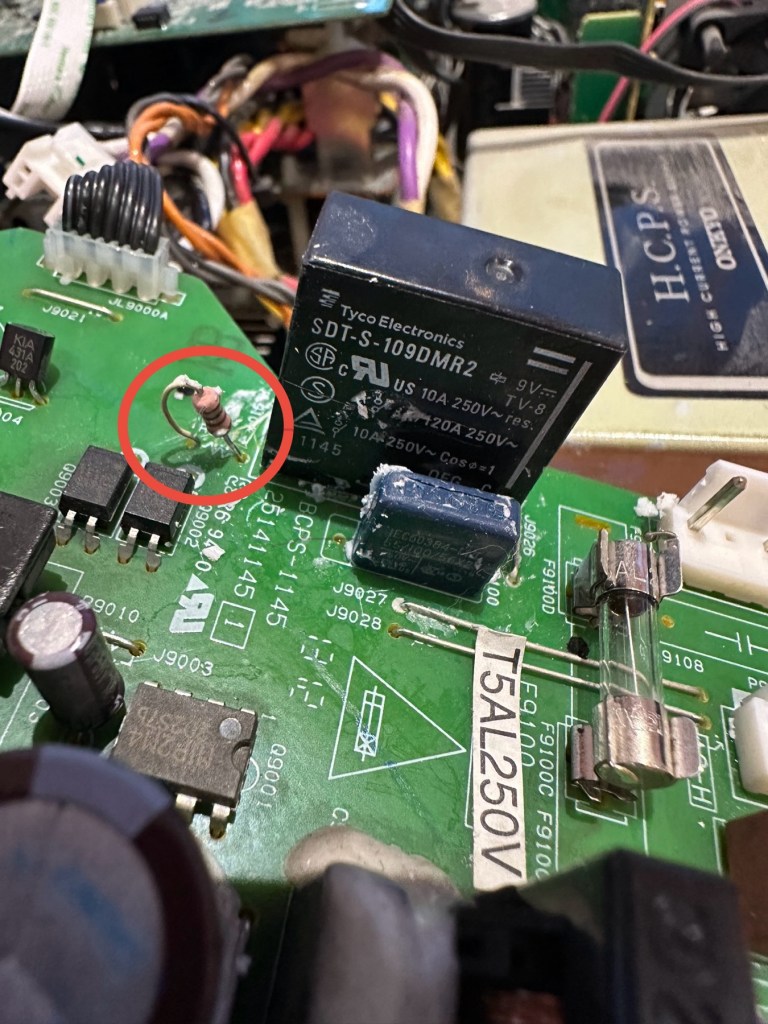

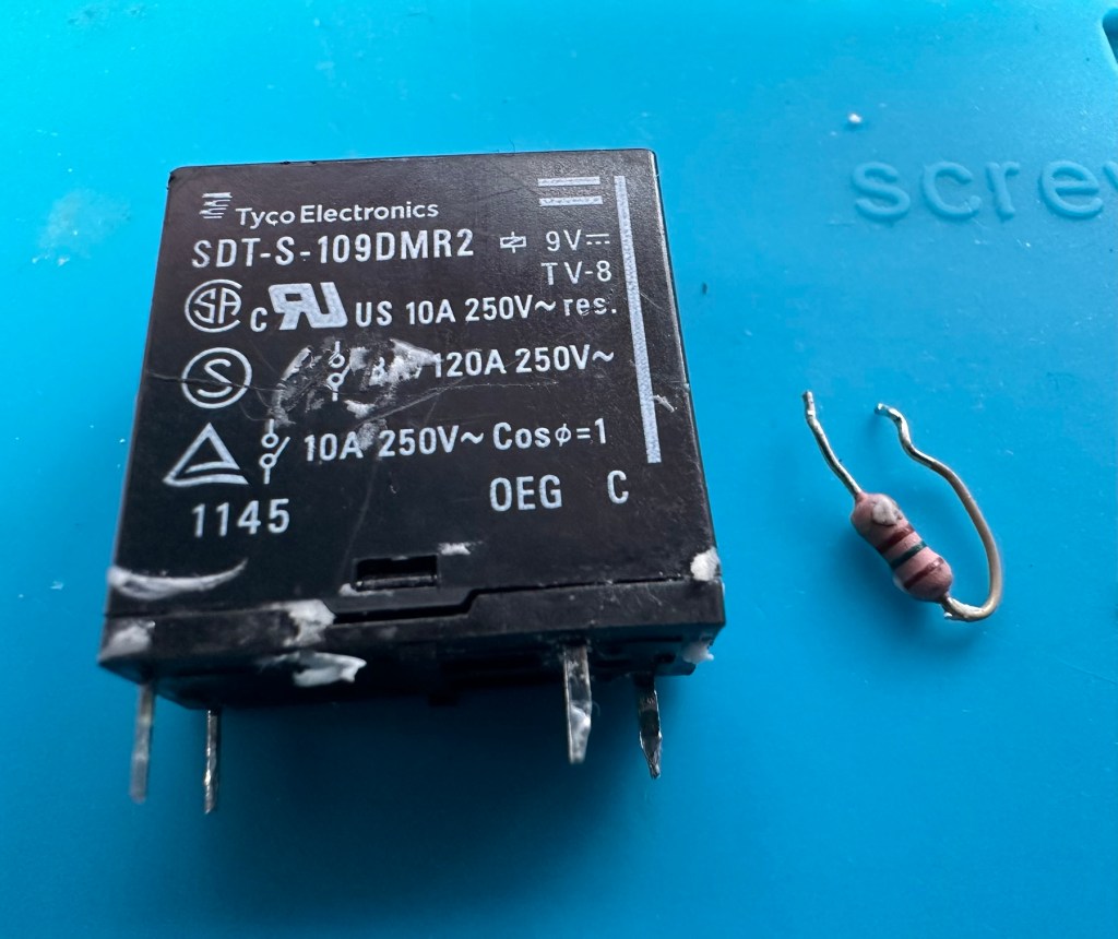

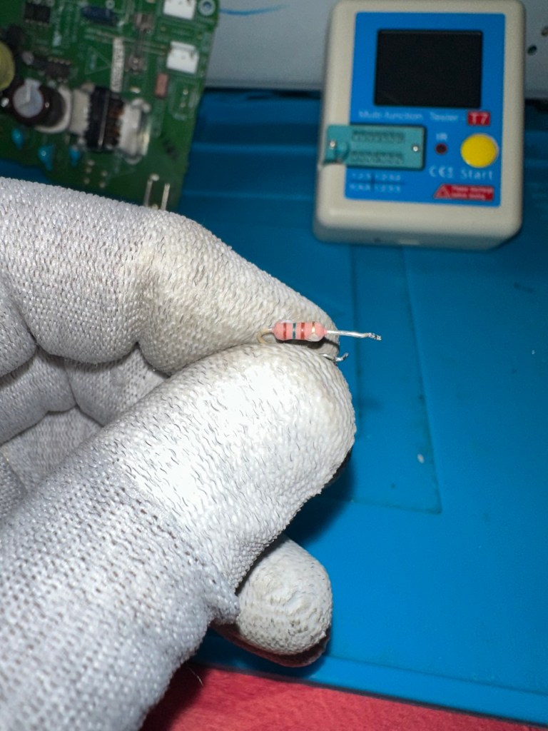

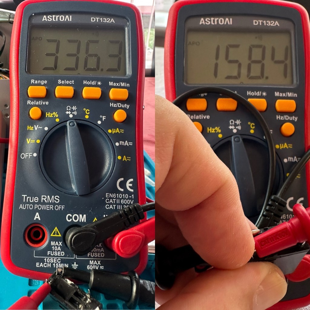
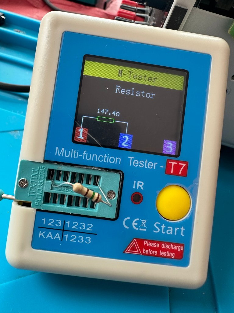

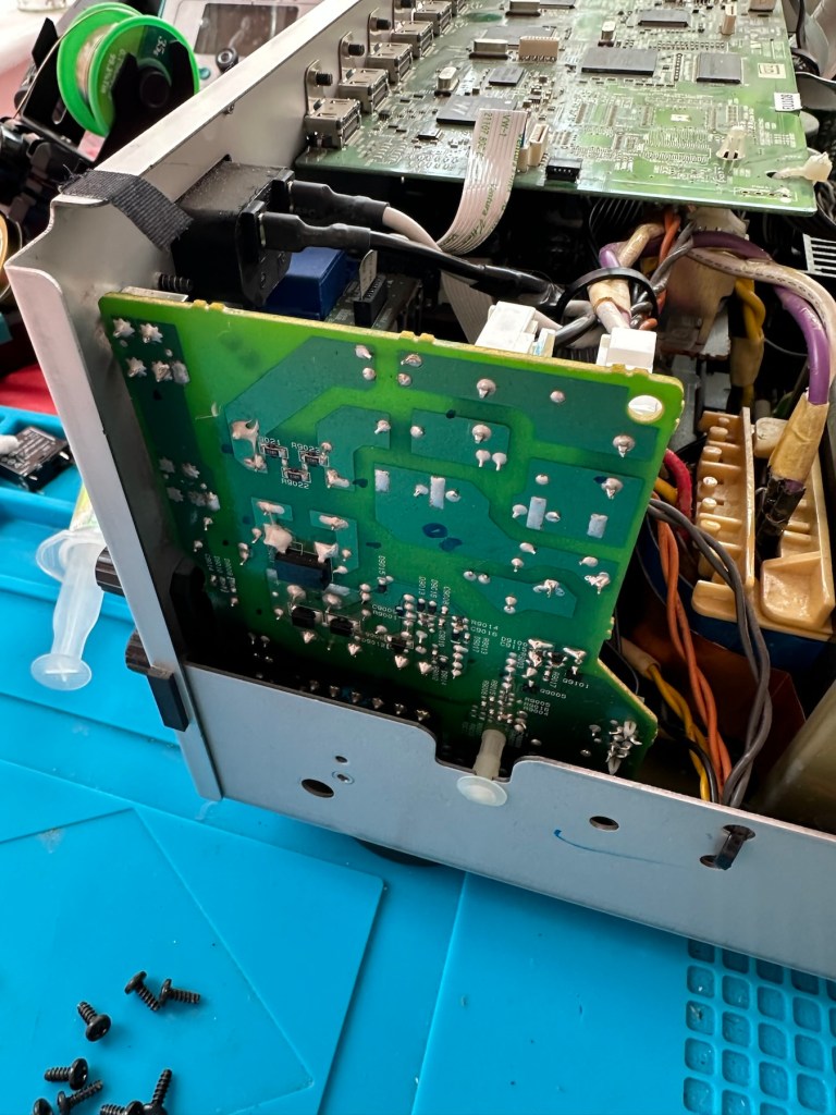

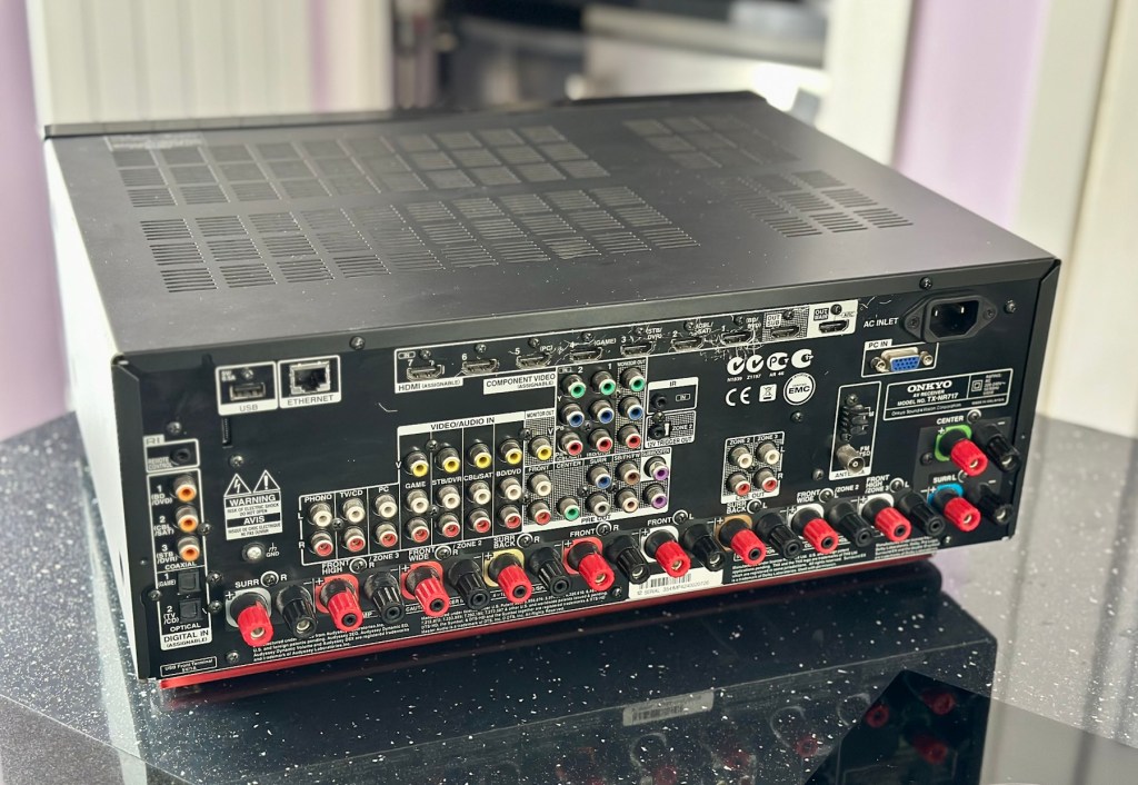
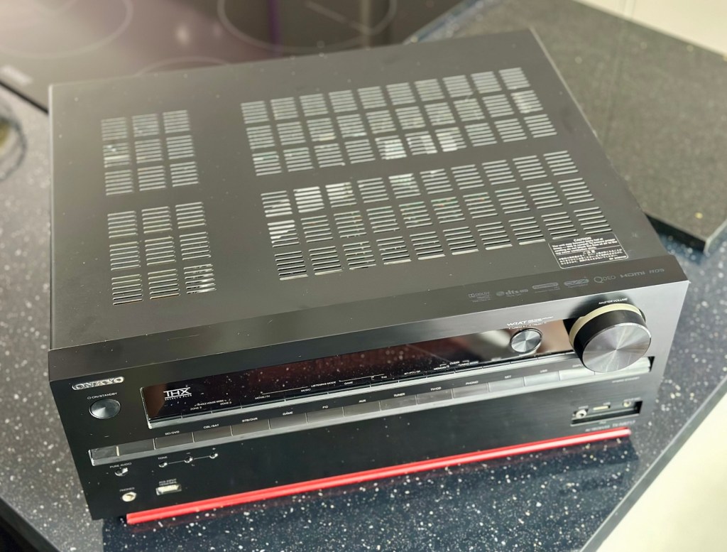
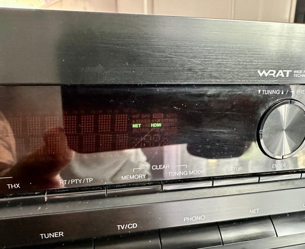

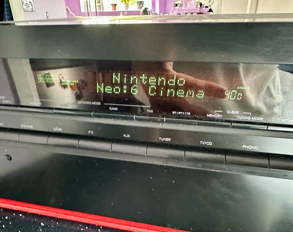
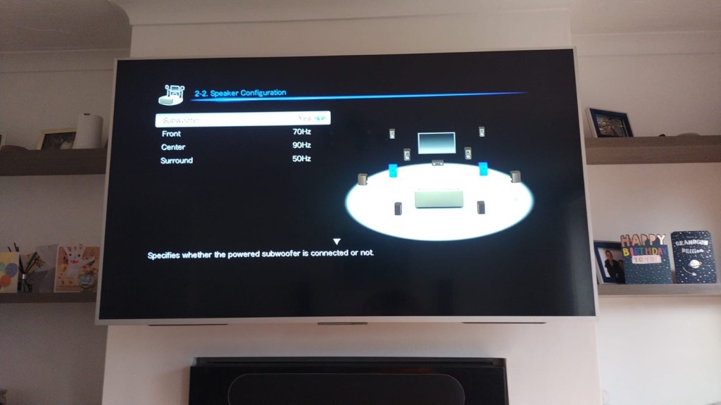
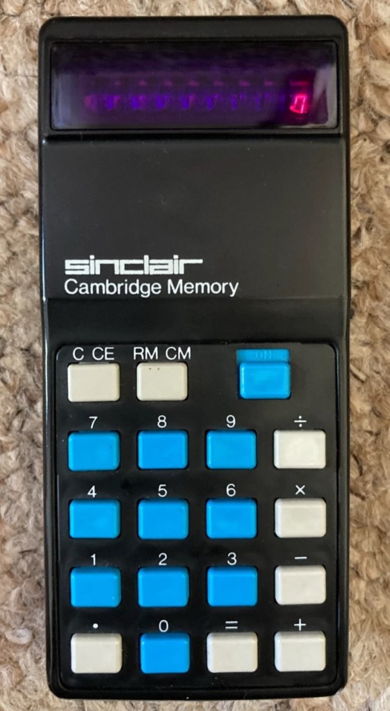
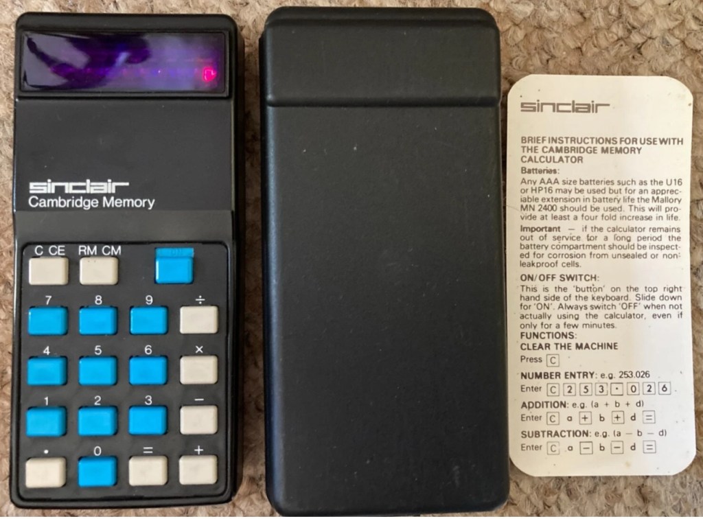
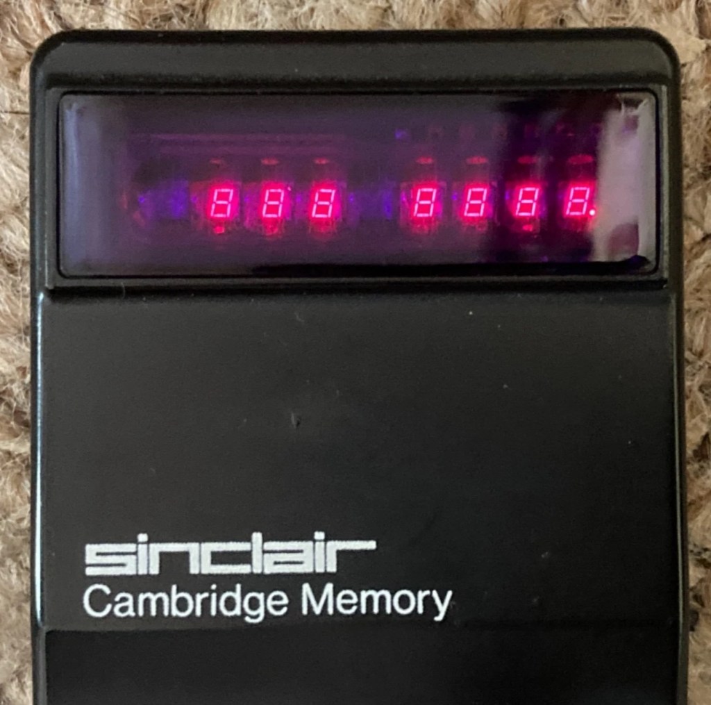

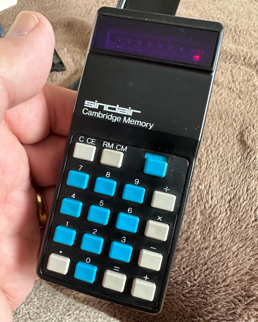


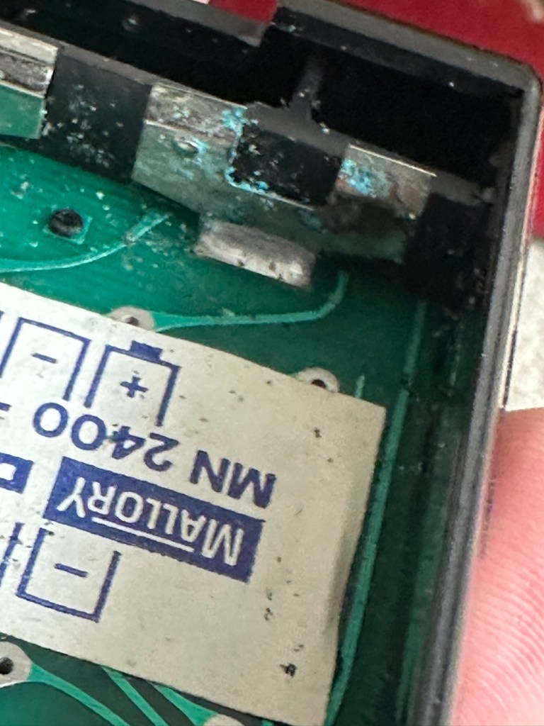


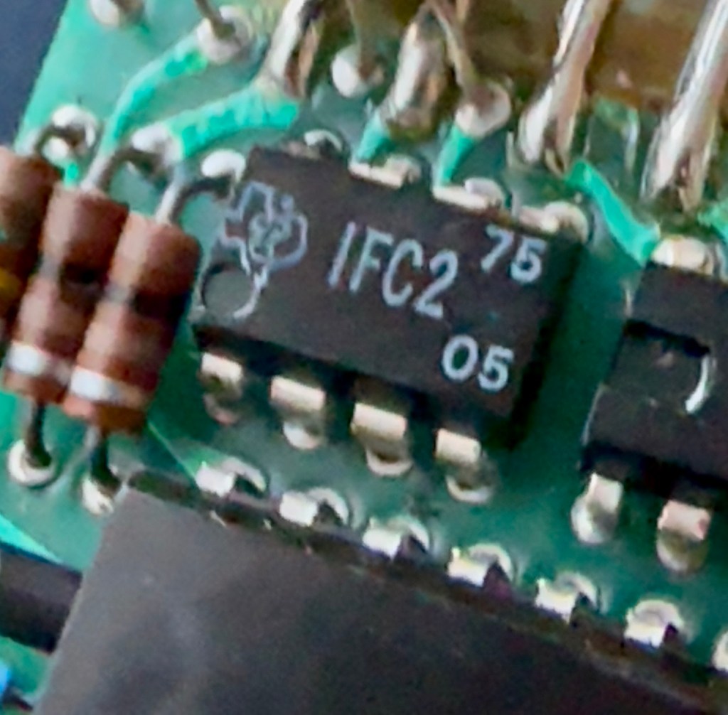
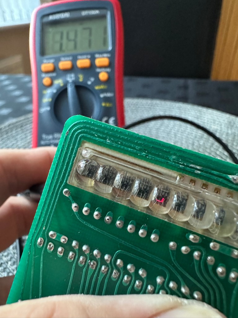


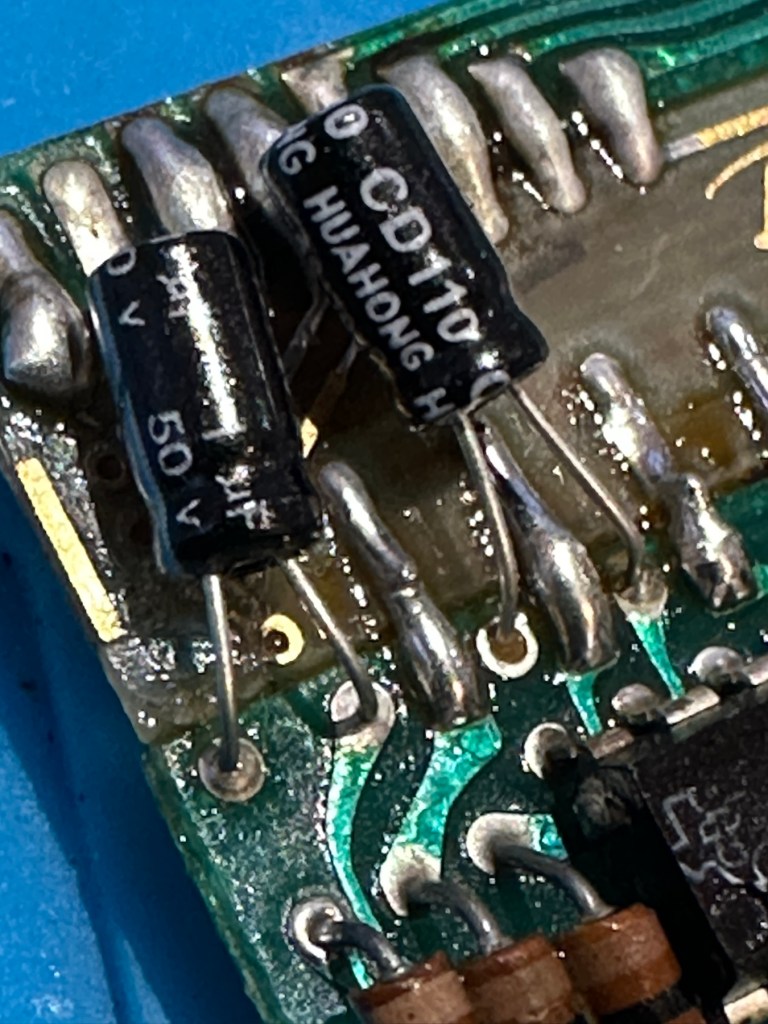

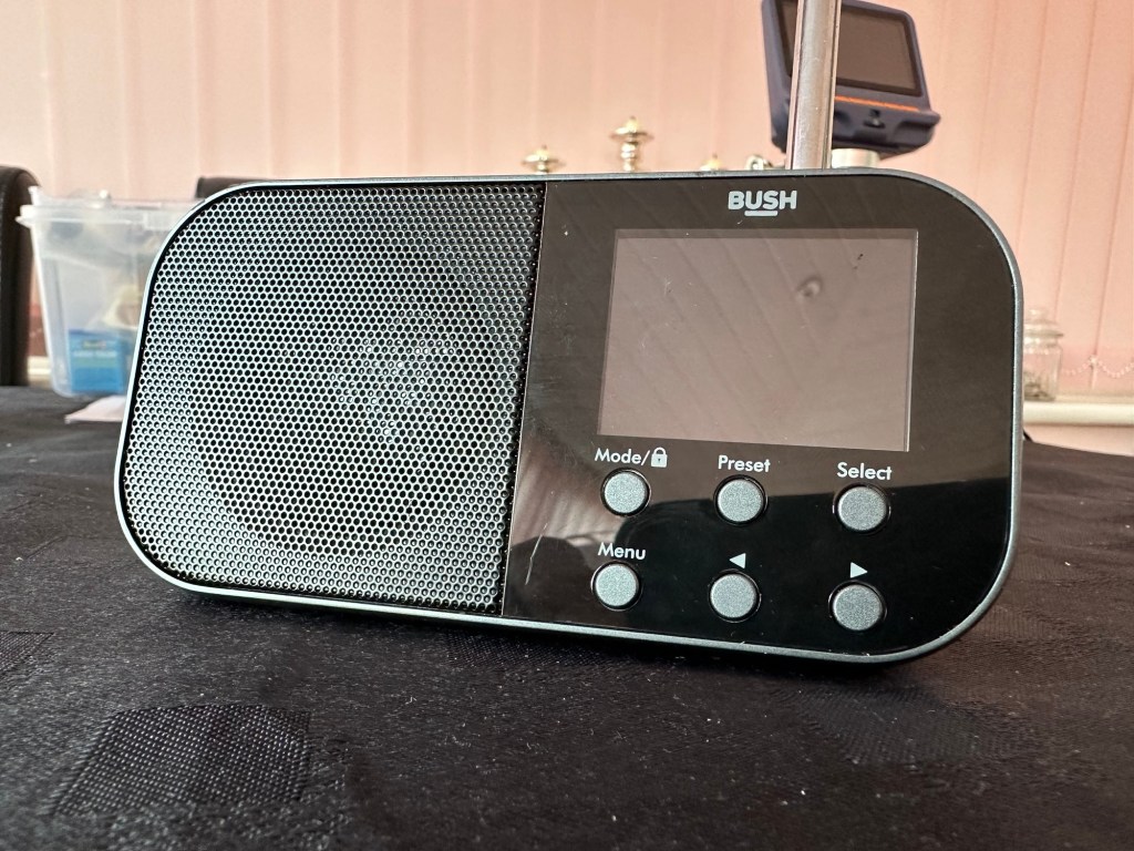
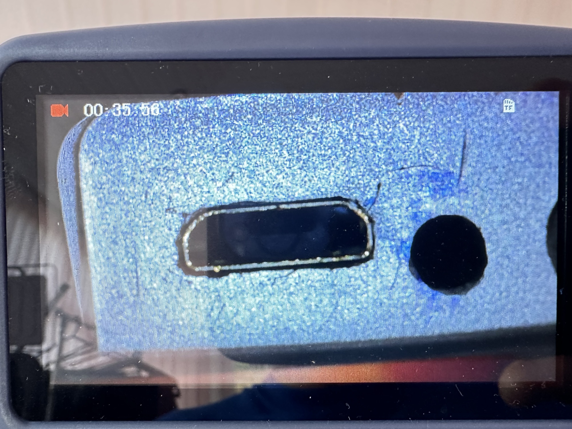

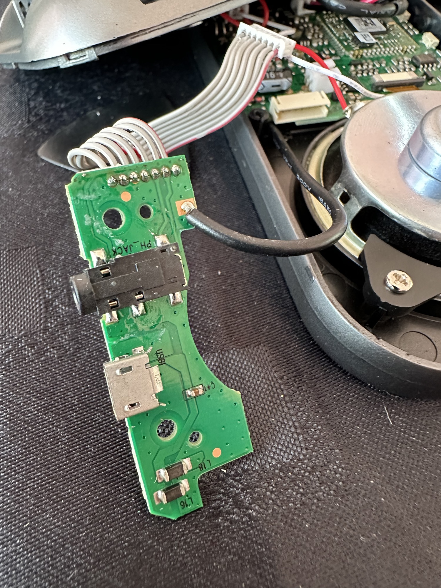

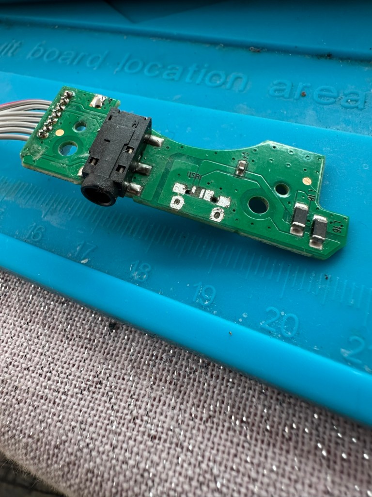
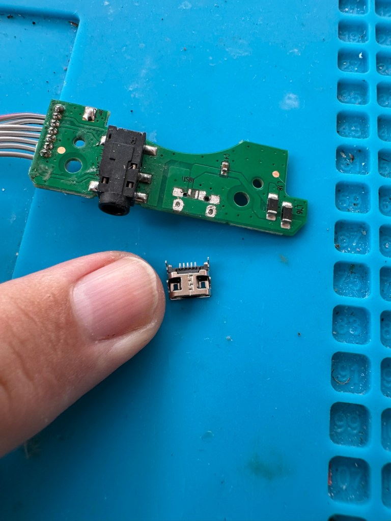
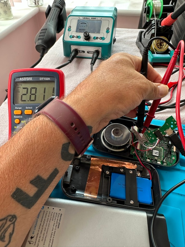
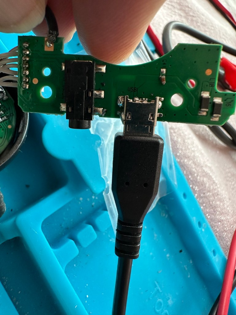


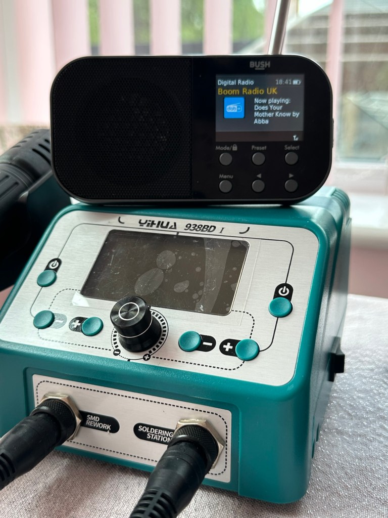


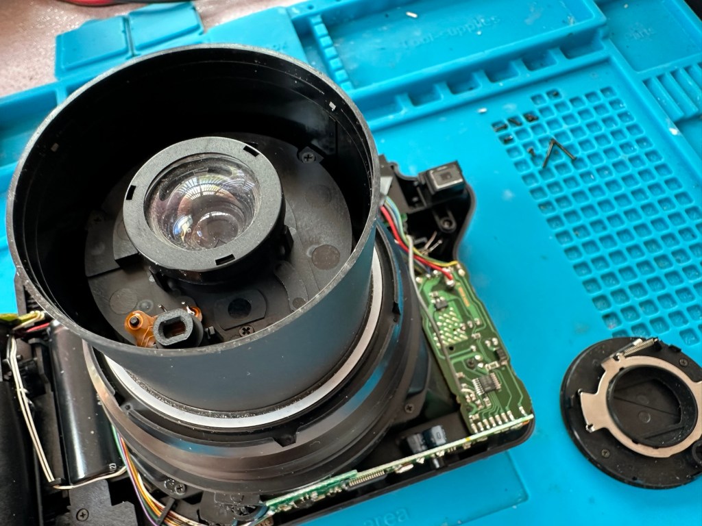
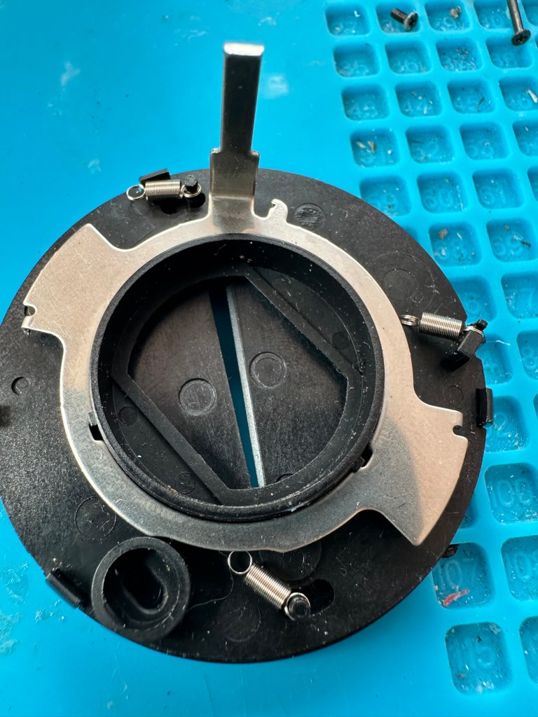
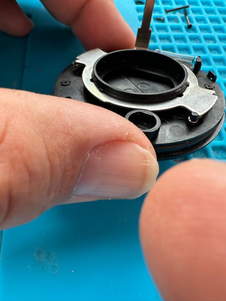

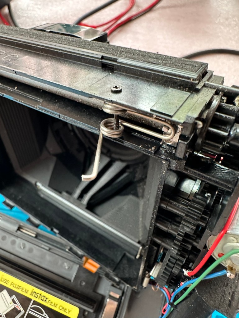


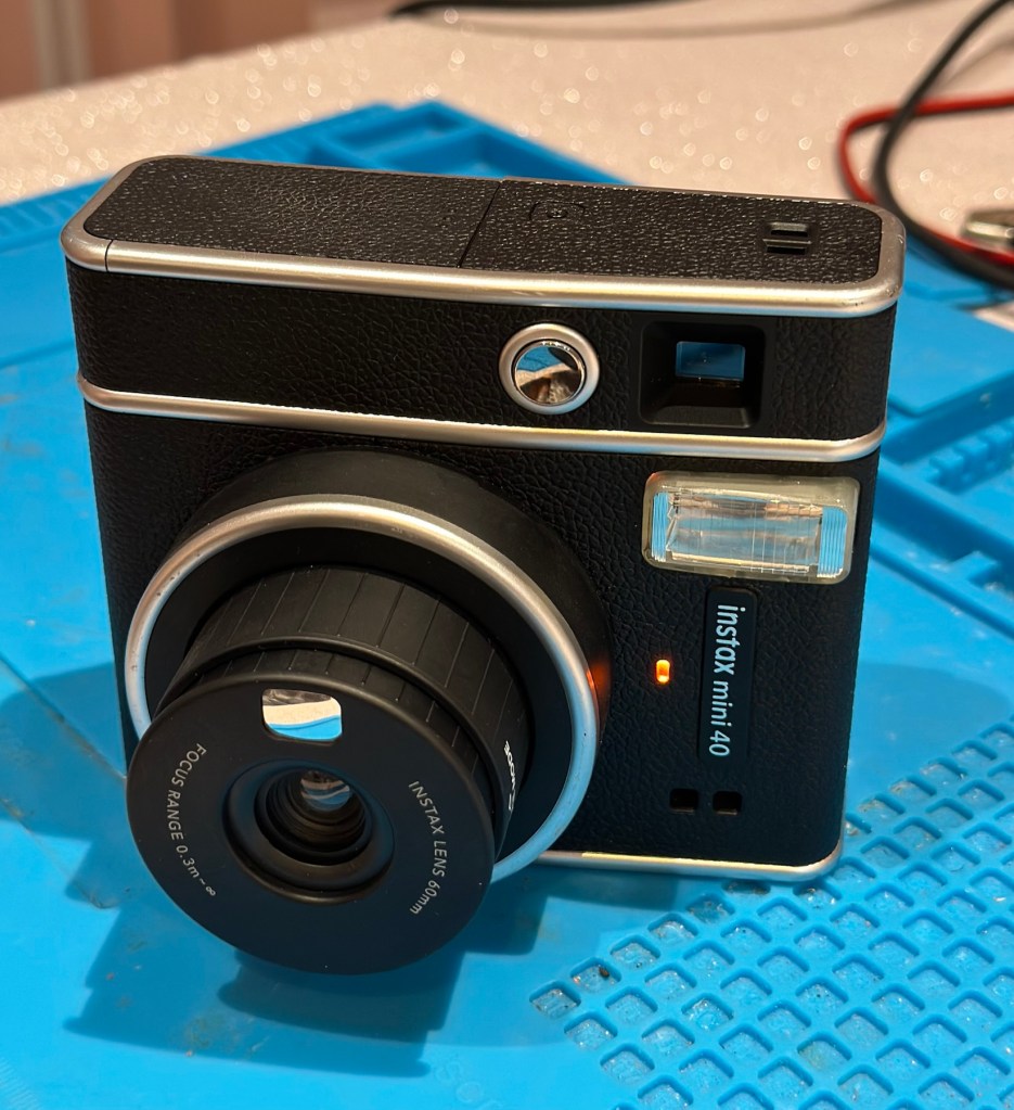
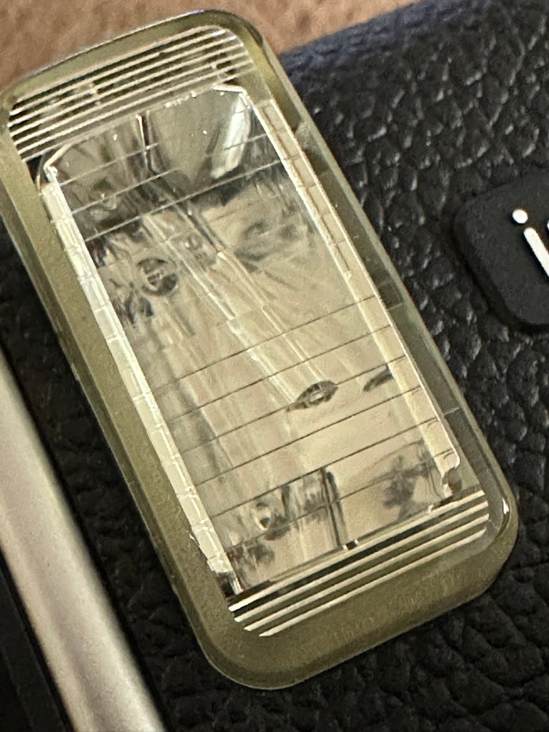
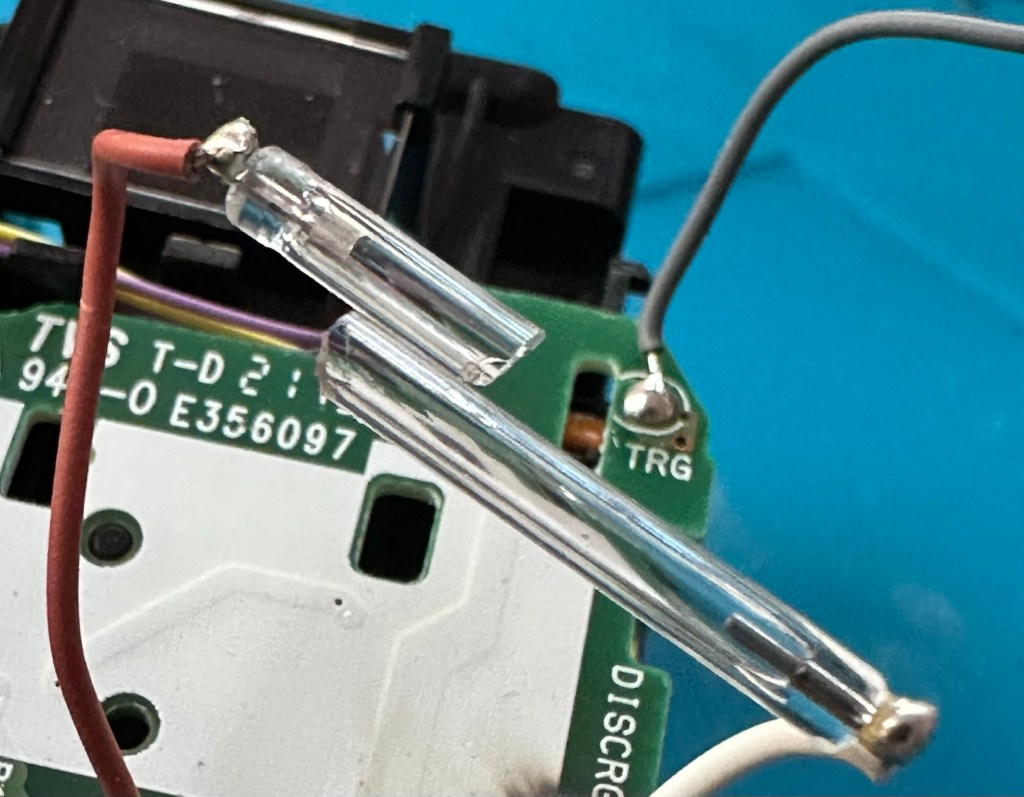

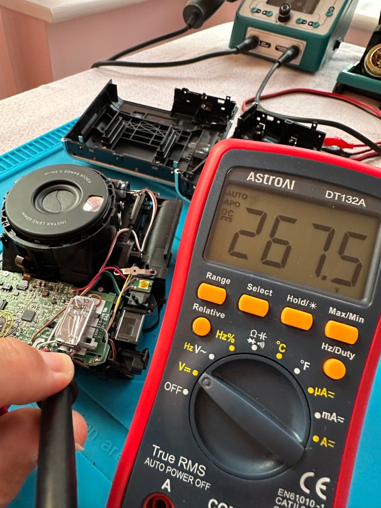

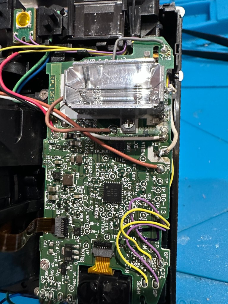
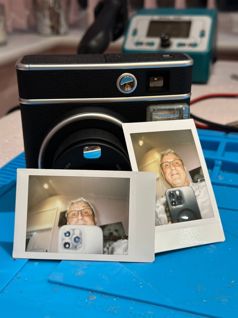


You must be logged in to post a comment.