

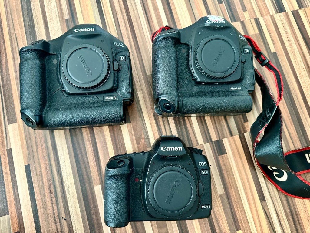
I’ve been approached by an old colleague who used to be a syndicated sports photographer, he had a number of items he wanted to “get rid off” as they were just taking up space in his new house. “Would you be interested?” You betcha, so as a result I’m now the owner of a complete Bowens lighting system, two Canon EOS 1D MkIV cameras and a Canon EOS 5D MkII camera.
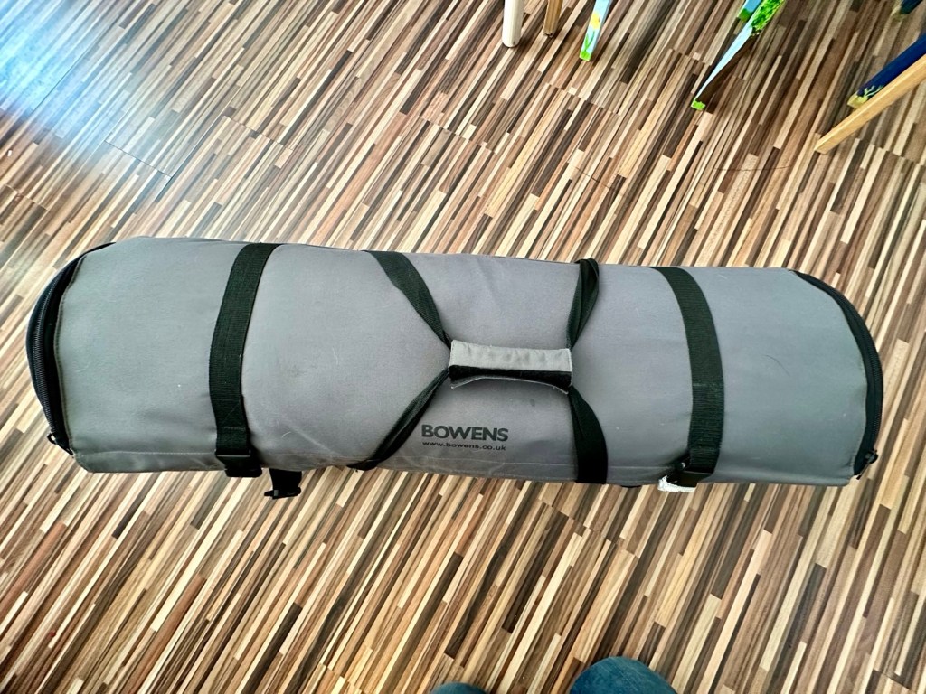
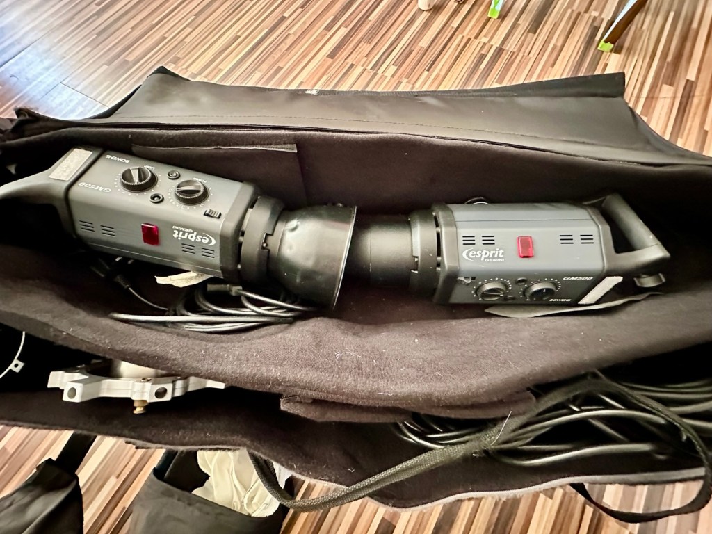
My days of fussing and farting about with lighting rigs has now long passed, so I know a youngster starting out in the business who is a very talented young fellah, I have donated this equipment to him and he will certainly have a use for this lighting setup. He has been approached and accepted the offer, I think he is quite happy with his new acquisition, here’s hoping his talents continue to flourish.
However the cameras are mine as no one wants this old stuff anymore 😂
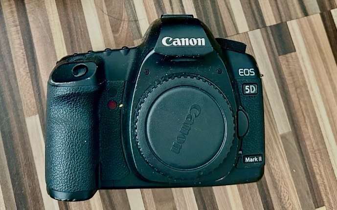
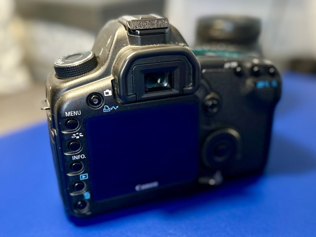
Having already in the past, repaired a film version of the EOS 1 here: Canon EOS1 N HS I have now become the owner of two Canon EOS 1D MkIV versions, the digital upgrade of this superb camera. This post covers the assessment of the 1D’s the 5D can be found here: Canon EOS 5D MkII
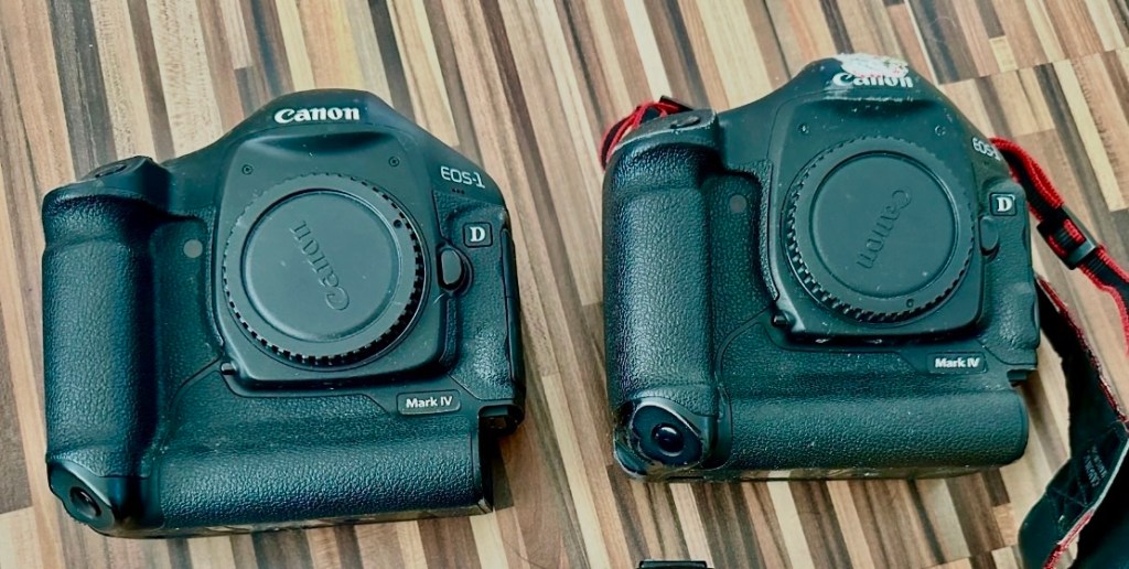
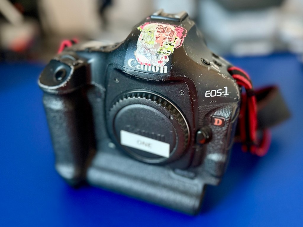
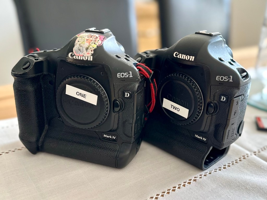
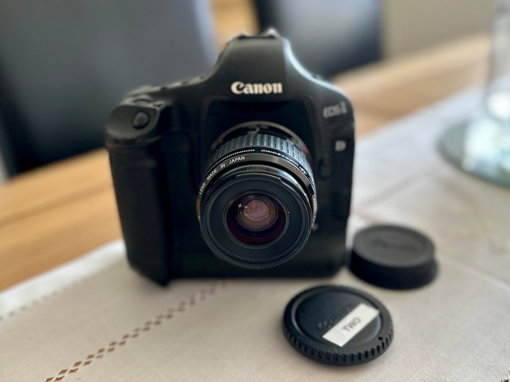
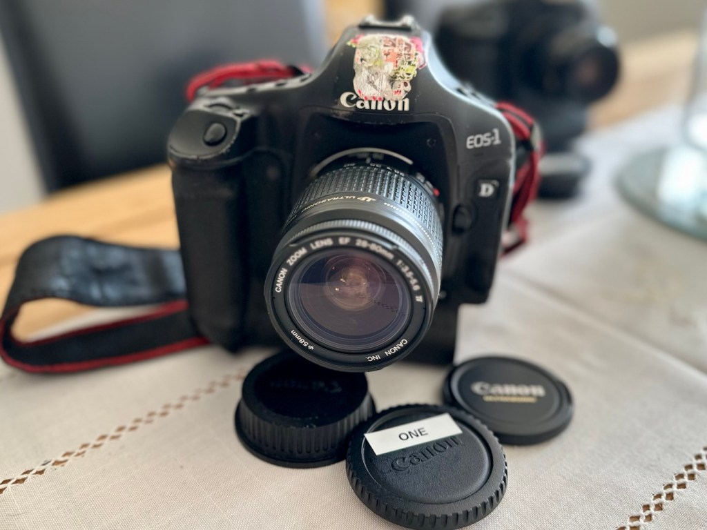
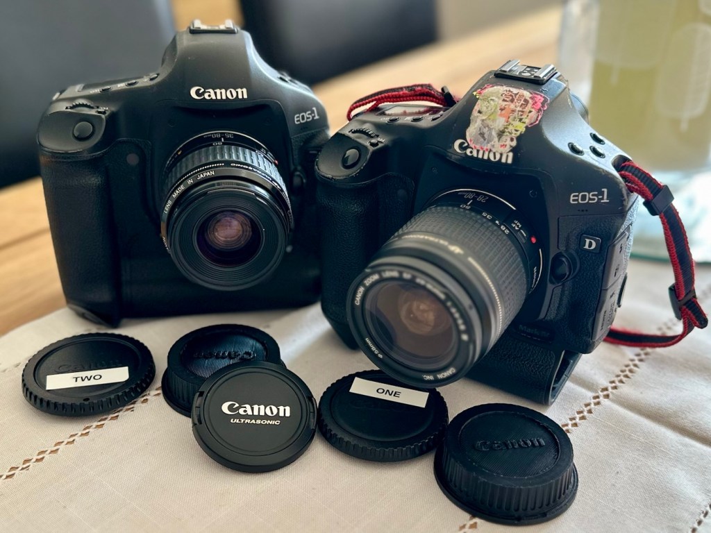
To test these two beauties I’m going to have to invest some money into my equipment store. These cameras take a battery that neither came equipped with, an EP4 battery that currently costs around £19.00GBP per unit. On top of that a charger is required costing approximately £23:00GBP so there will have to be an outlay of approximately £42:00GBP just to get these units tested. Is it worth it? Yes, I think it is, I will then have a spare battery and charger for future use, and if the cameras don’t work? I can then sell them on or use them for spare parts as they have cost me absolutely nothing. When I go through the assessment and repair of these cameras I will refer to them one camera at a time. The camera that has stickers on the top of the camera pentaprism area will be referred to simply as “One” whilst the other will be “Two”. Nice and uncomplicated.
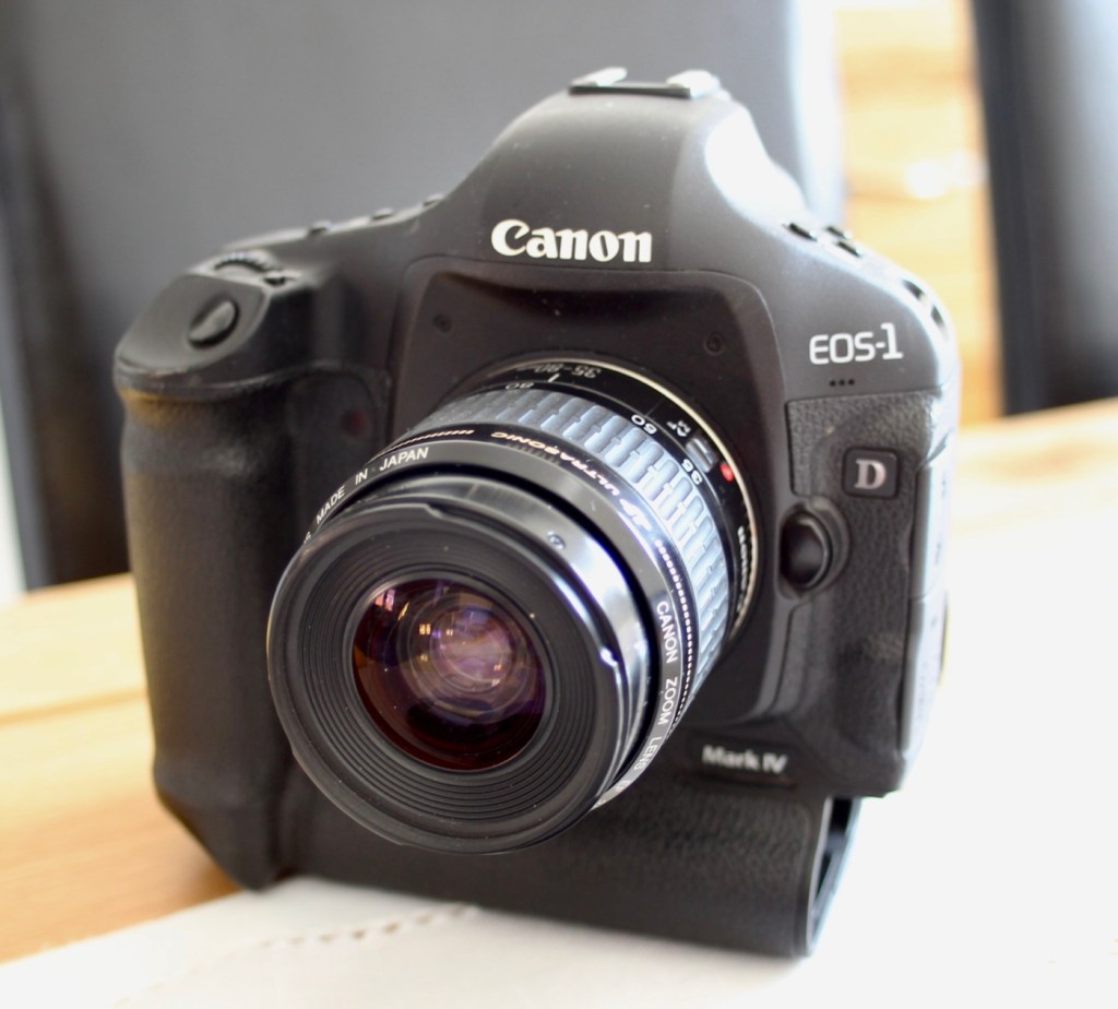
But first here is a little bit of information regarding this camera, the Canon EOS-1D MkIV.
The EOS-1D Mark IV is a professional 16.1 effective megapixels digital single lens reflex camera (DSLR) camera body produced by Canon. The EOS-1D Mark IV is the successor of the Canon EOS-1D Mark III and was announced on 20 October 2009, just four days after Nikon announced the D3s. It used to be the only Canon APS-H format DSLR to feature HD video recording at 1080p resolution.
It was discontinued in mid-2012 with the introduction of the Canon EOS-1D X, which replaced both the EOS-1D Mk IV and the EOS-1Ds Mk III.
It received a Gold Award from Digital Photography Review.
Features:
- 27.9mm × 18.6mm; 16.1 effective megapixels APS-HCMOS sensor
- Dual DIGIC 4 image processors
- Canon EF lens mount (excludes EF-S)
- New autofocus module (45 AF points with 39 cross-type AF points)
- Integrated sensor cleaning system
- 1.3× crop factor
- 100–12800 ISO speed equivalent (expandable to L: 50, H1: 25600, H2: 51200 or H3: 102400)
- 30–1/8000 sec. shutter speed and bulb
- Shutter unit tested to 300,000 cycles
- Auto Lighting Optimizer
- Magnesium Alloy weather sealed body
- Eye-level pentaprism viewfinder with approx. 100% coverage at 0.76× magnification
- Live preview mode
- 3.0 in, 920,000 dots Clear View II TFT color, liquid-crystal monitor with 160° viewing angle
- 10 frames per second continuous shooting (Large JPEG: max. 121 frames, raw: max. 28 frames)
- Dimensions (W×H×D): 156 × 156.6 × 89.9 mm
Wikipedia
Assessment:
I’ve had to bite the bullet and purchase a battery and charger to be able to test these cameras. Look at it as an investment. As promised the assessments will include exactly the same checks, but they will be done individually.
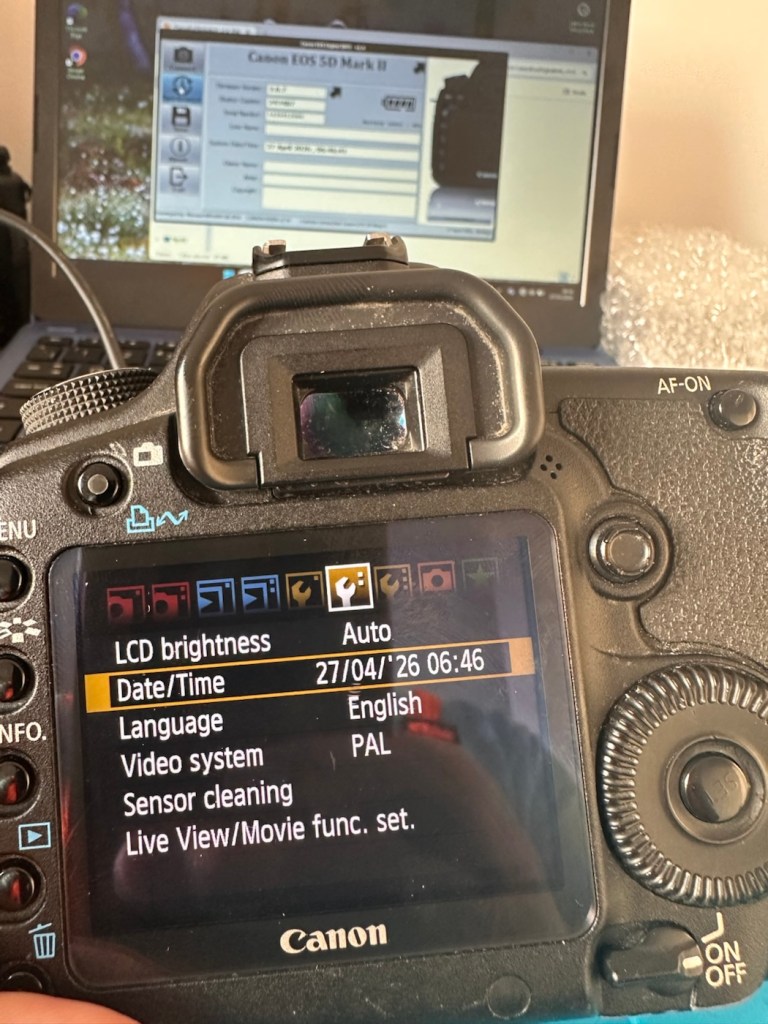
I want to check shutter counts and firmware versions, but to carry out these tests I really do need power in the units. Clock backup batteries are installed on these cameras and these will need to be checked to see if they are still effective as I’ve no idea how long ago they were changed.
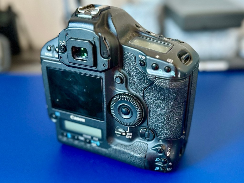
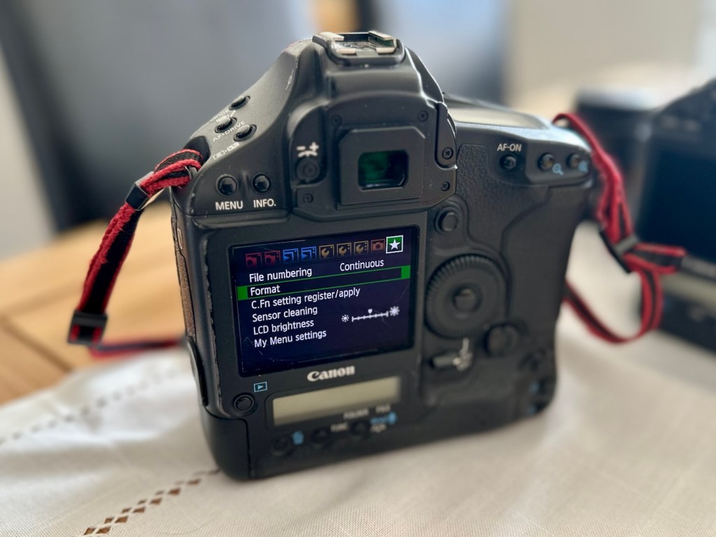
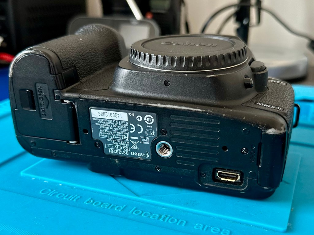
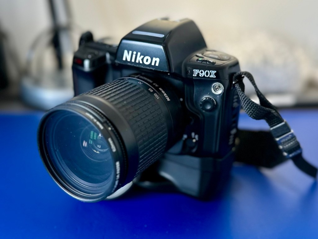
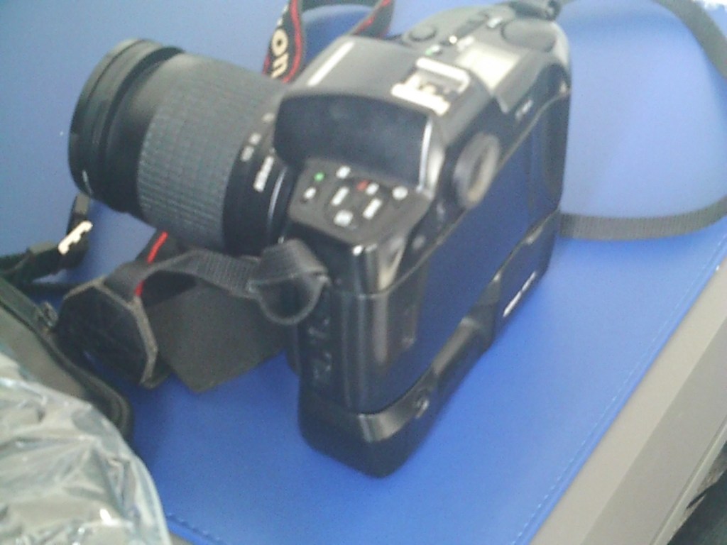
Camera one:
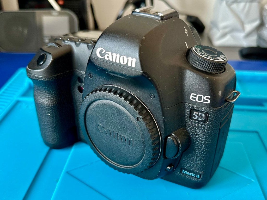
Here are the pictures:
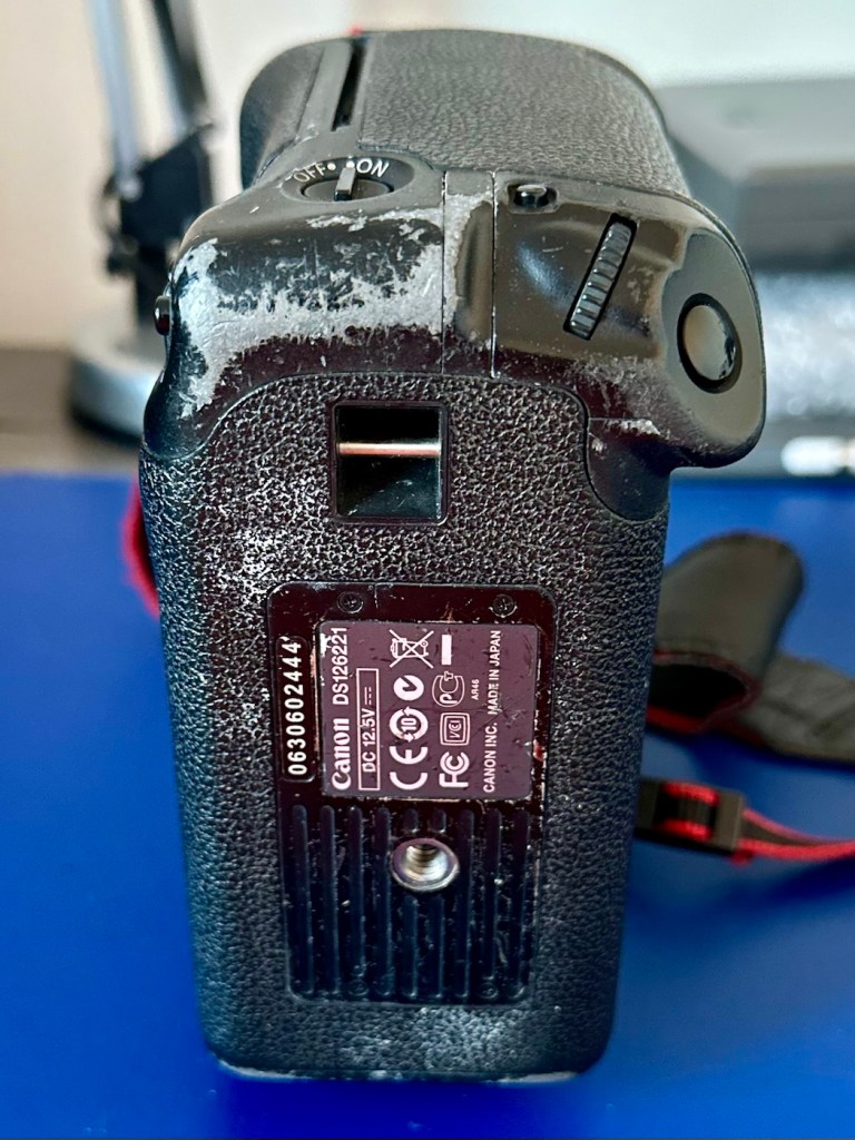
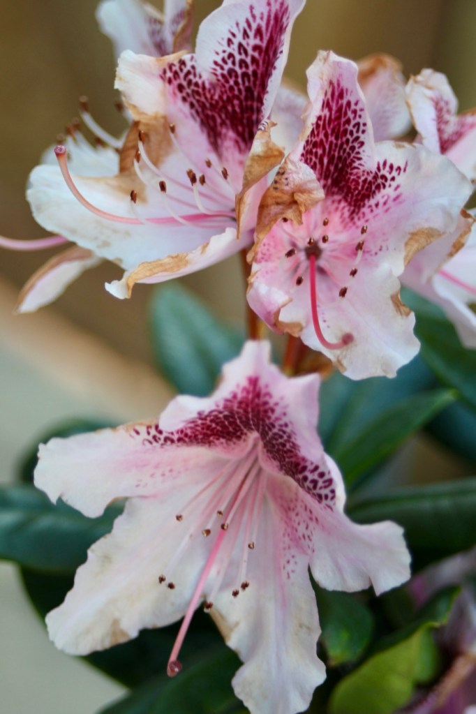
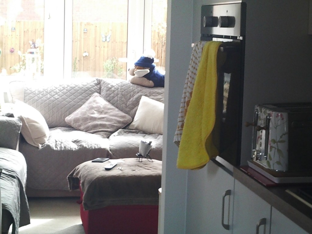
I can pretty much pinpoint the last time this camera was used, as in the CF card slot there was a 16GB card installed and when downloaded there were six photos on the card, below you can see two of these images.
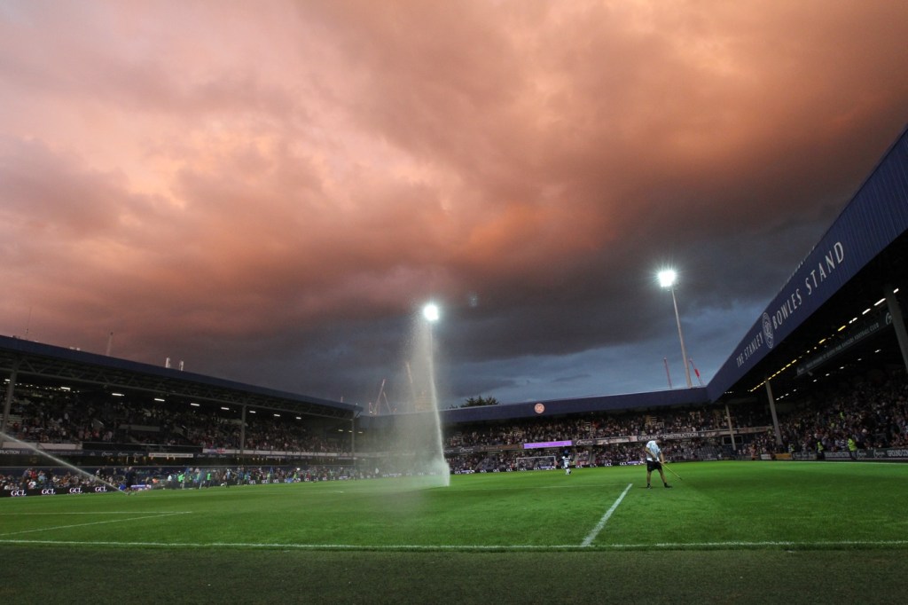

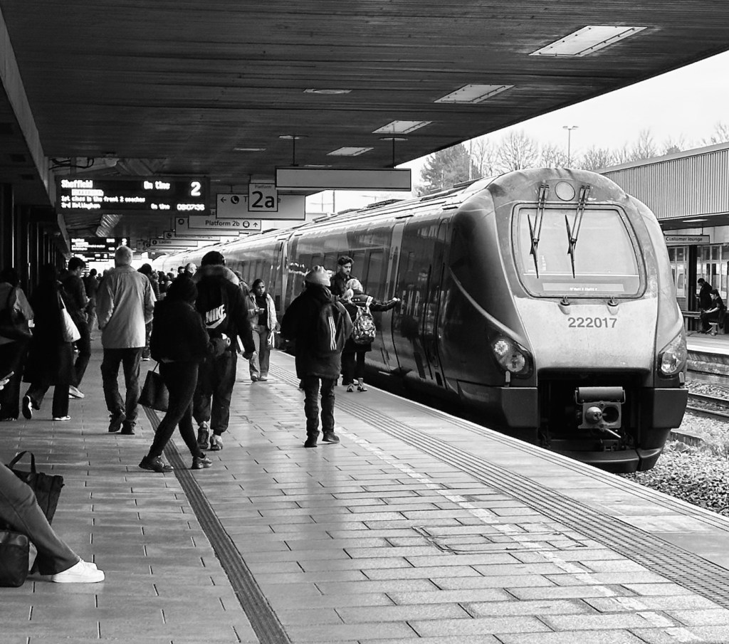
The photos show a football ground, it’s the Queen’s Park rangers ground in London, and you can see the Stanley Bowles stand just to the right. The photographer is in the usual position where you would find sports photographers attending a football match. The exif data in the photo gives the date as 30th August 2022, and if you check records you will see that QPR were Playing Hull City that evening, and QPR were the winners 3-1. We have a date that informs us this camera was last used almost four years ago. Interesting isn’t it?
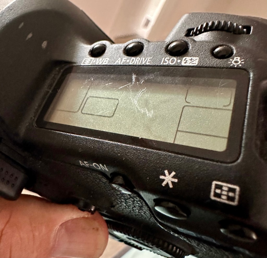
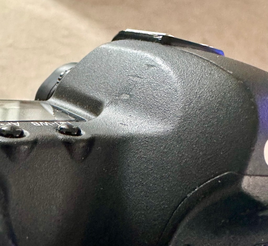
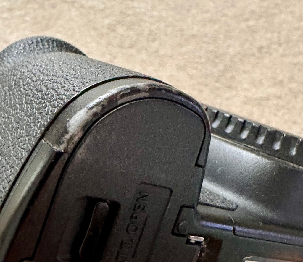
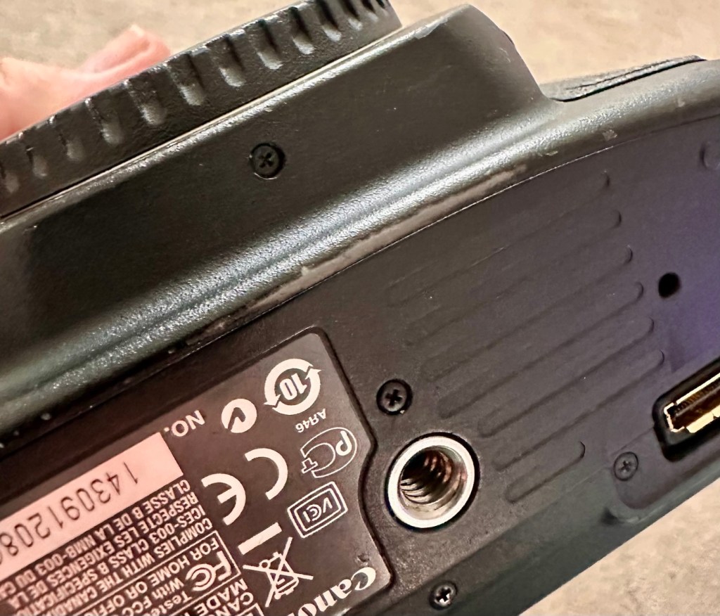
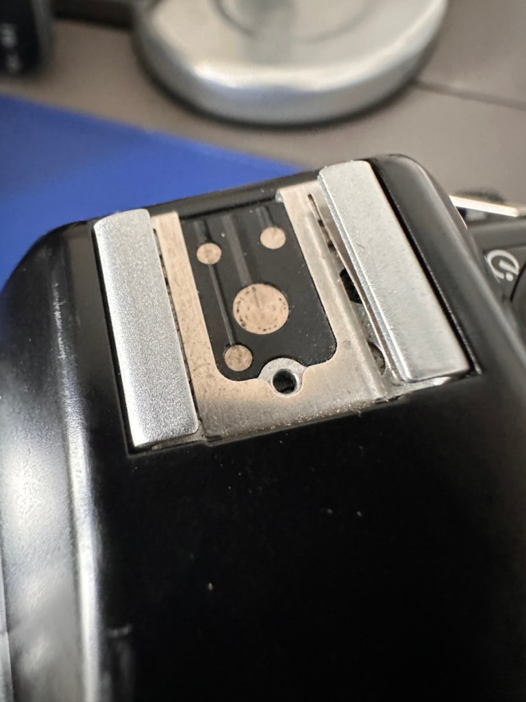
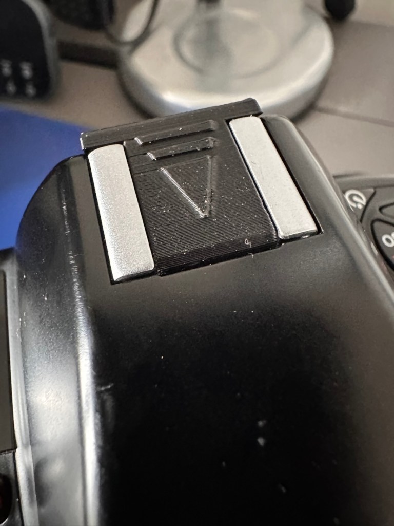
So of the two cameras this one seems to have had the hardest life, I very much suspect this one is the older camera (it is I have checked the Canon database and it’s construction date is June 2013, the second camera is October 2014) This date may seem contradictory due to the fact the production run officially ceased in 2012, It is very possible for a Canon EOS-1D Mark IV to have a 2014 manufacturing date, even though the camera was officially withdrawn in late 2012. Professional cameras often have long production runs that continue well after their retirement date. Cosmetically it appears the most beaten up and used, with a number of old press pass stickers in the pentaprism area. There are no signs though of deep gouges or cracked and damaged metal so I’m confident this camera has not been dropped. It has had a tough life. It’s a tough camera though.
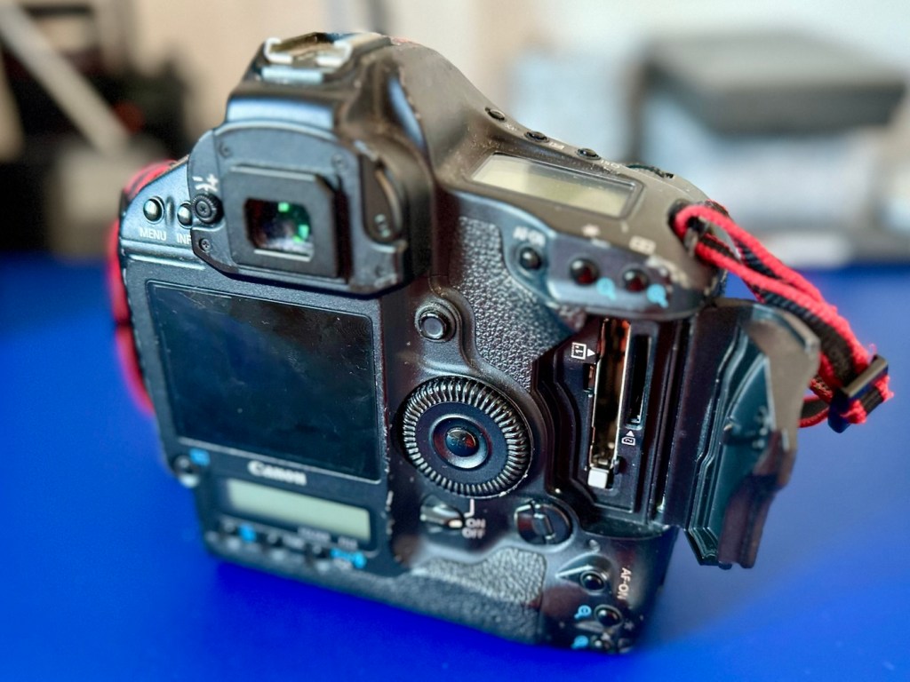
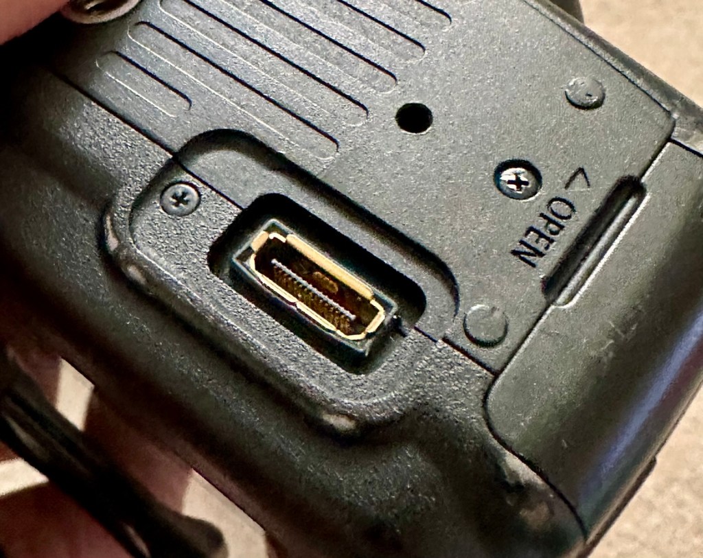
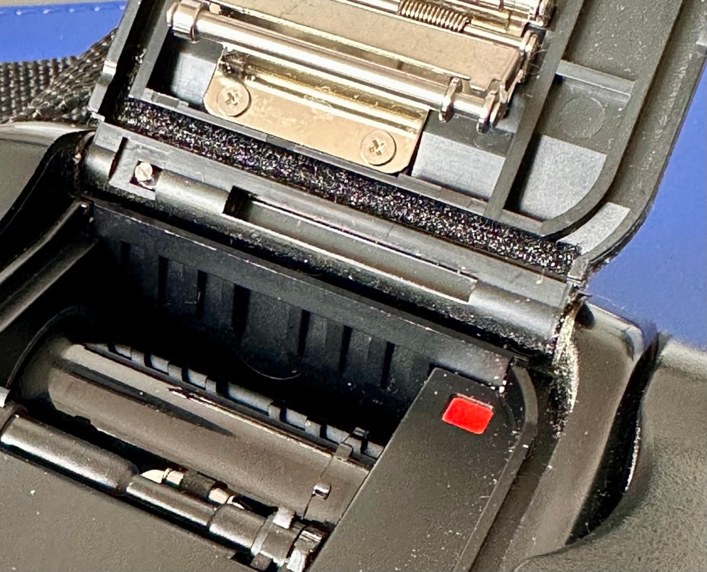
The CF card and SD card holders are both in a good condition, both accept cards without having to use any force and all pins are in a good condition, I’m confident there are no issues in the memory card area.
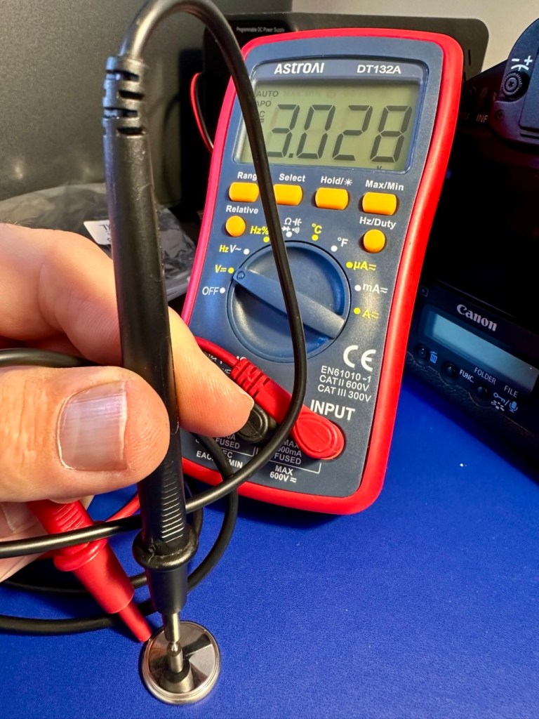
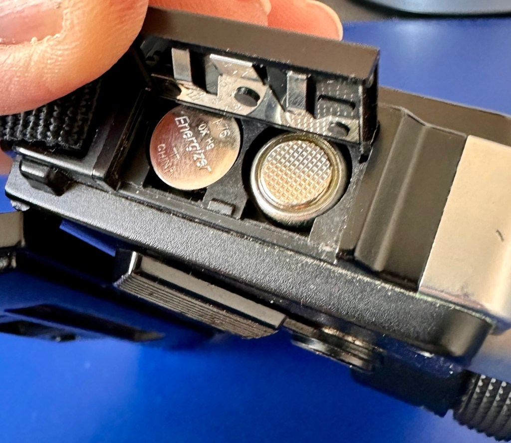
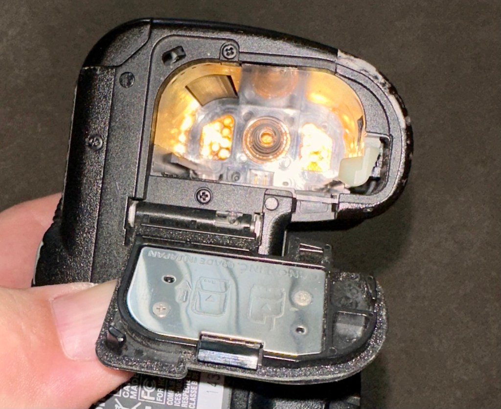
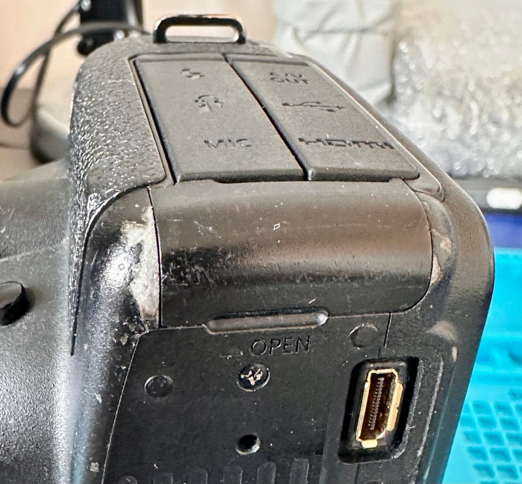
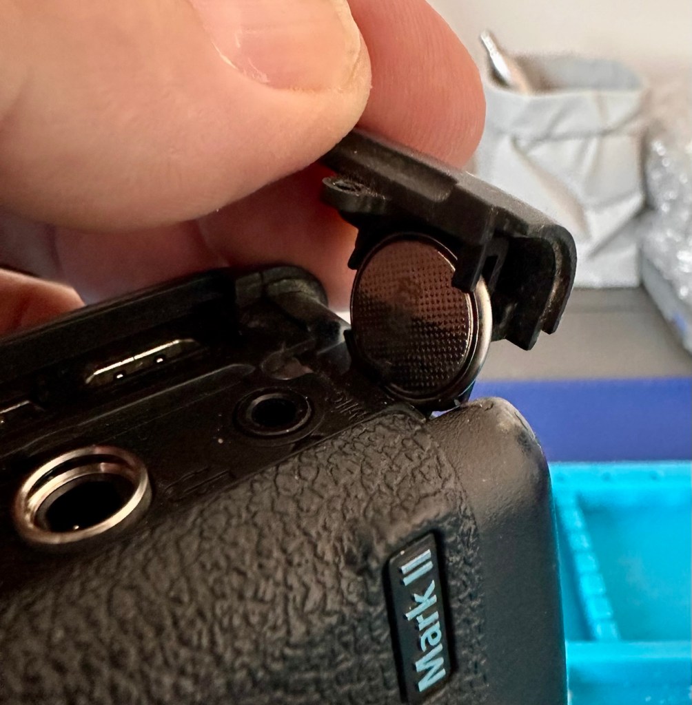
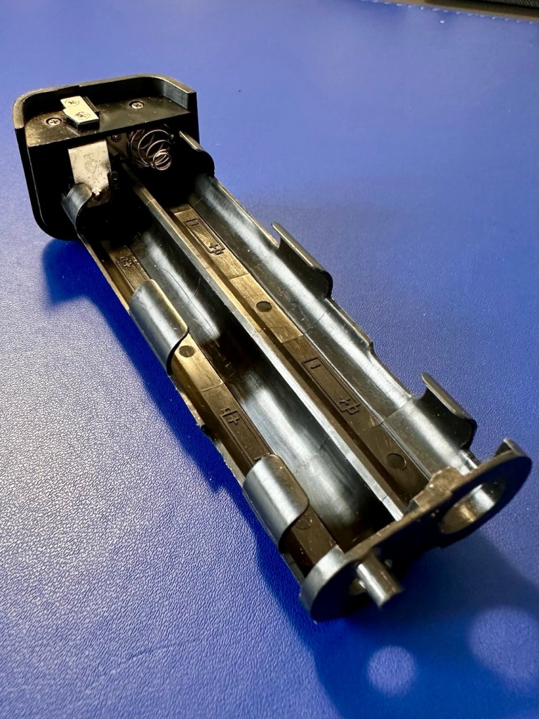
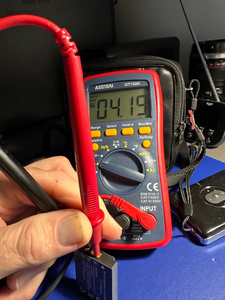
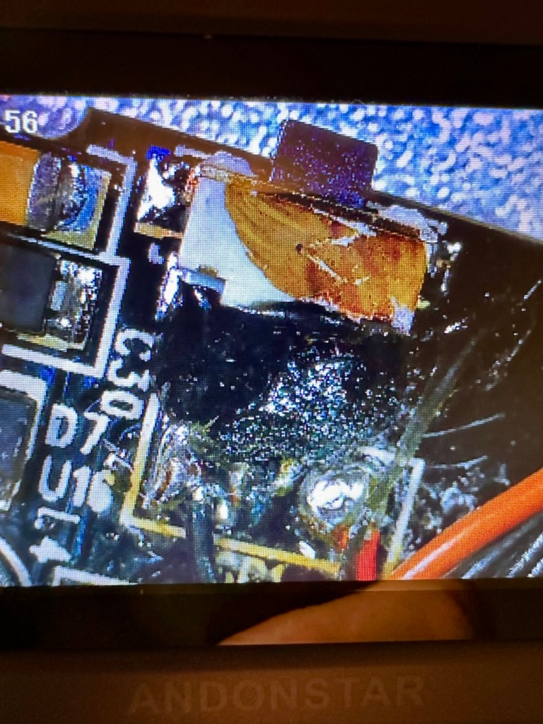
The clock battery is accessible at the point where the main battery fits in to place.
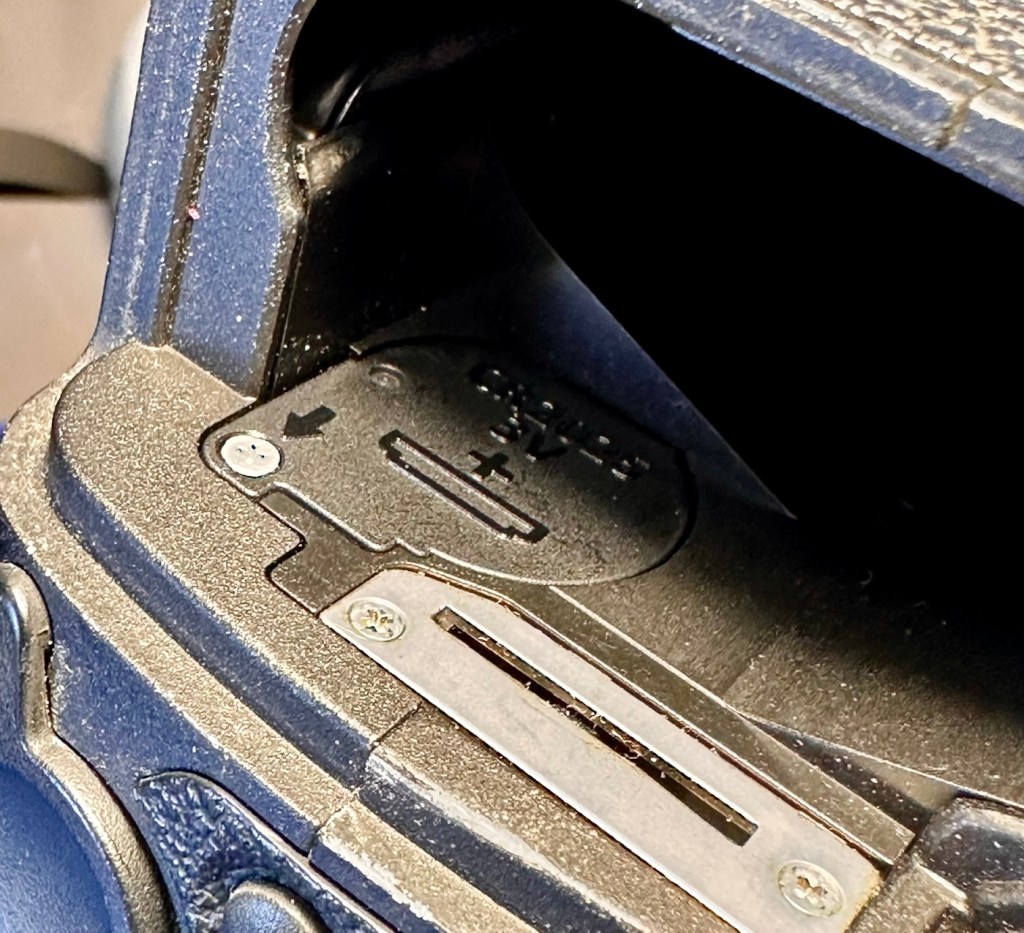
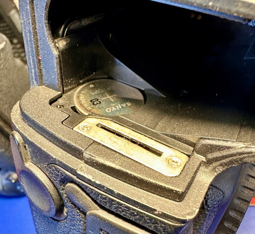
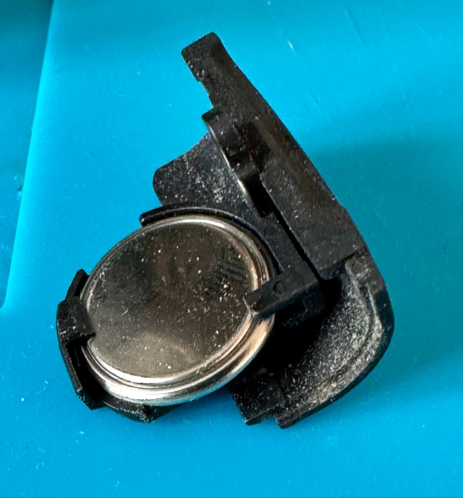
The battery is a CR2025 lithium coin cell. When tested the battery has a value of 3.028V. This is a sufficiently good charge for its purpose and is good seeing that this camera has not been used for the last four years.
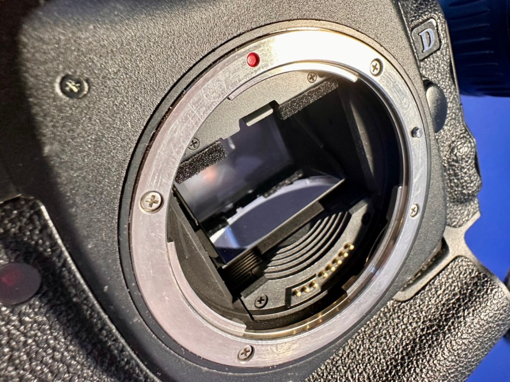
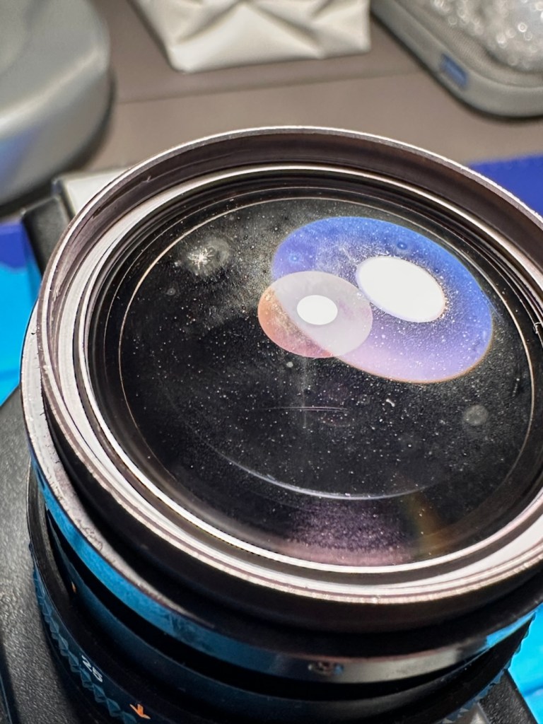
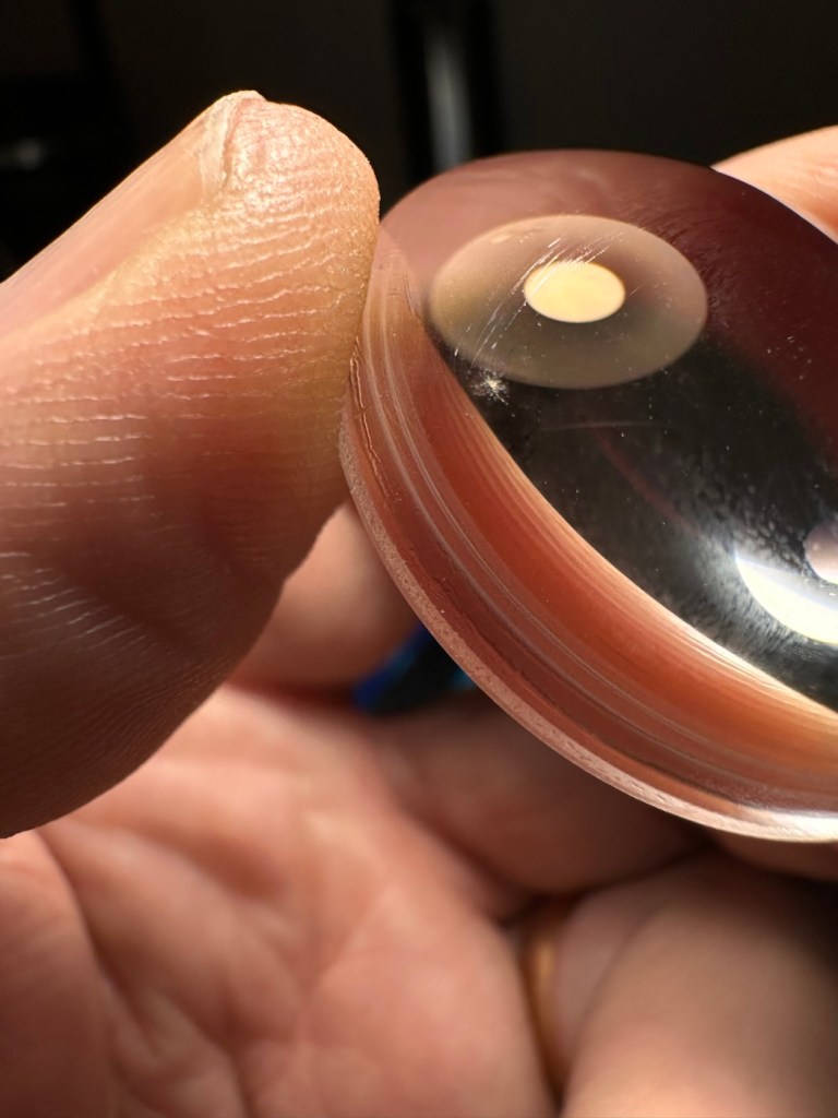
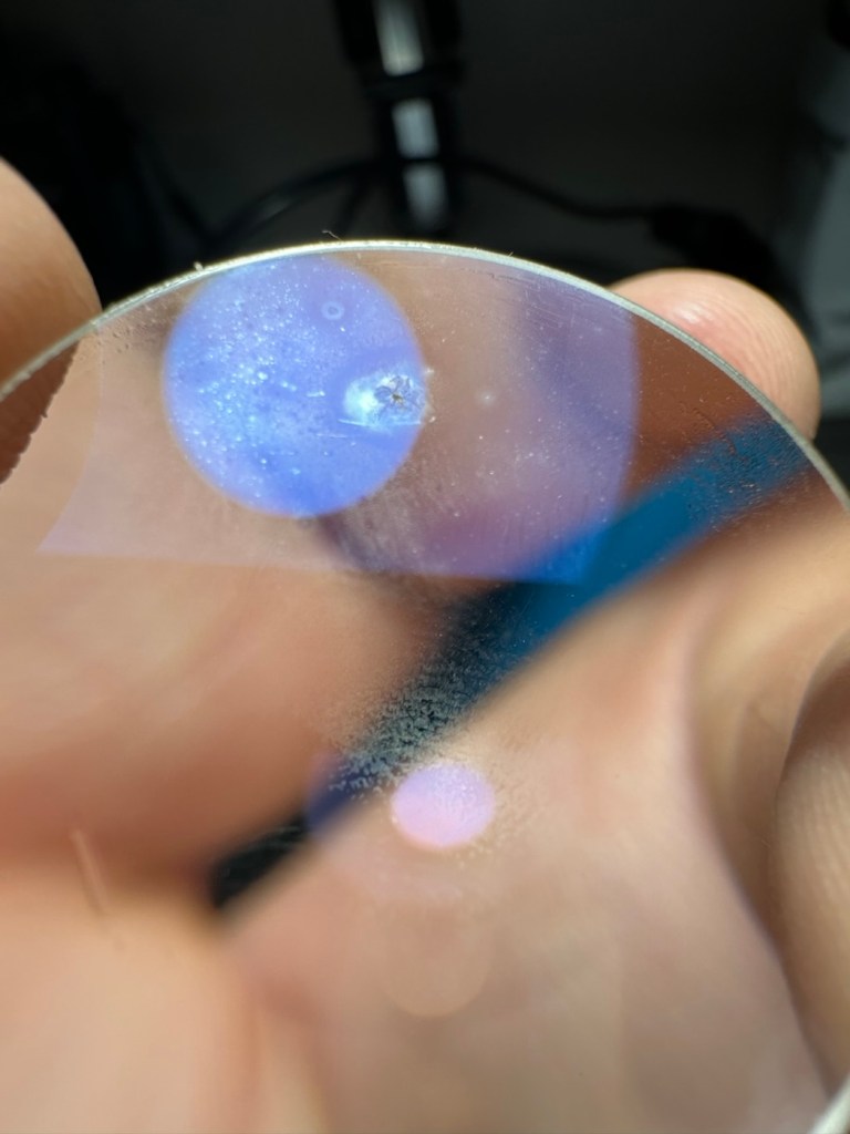
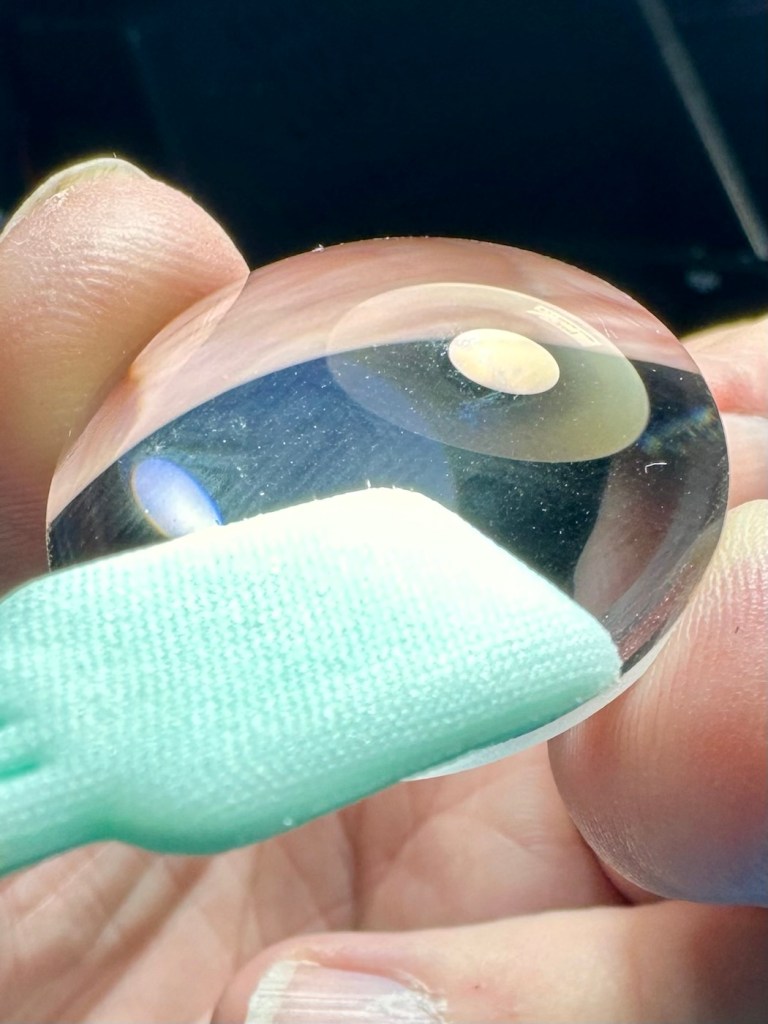
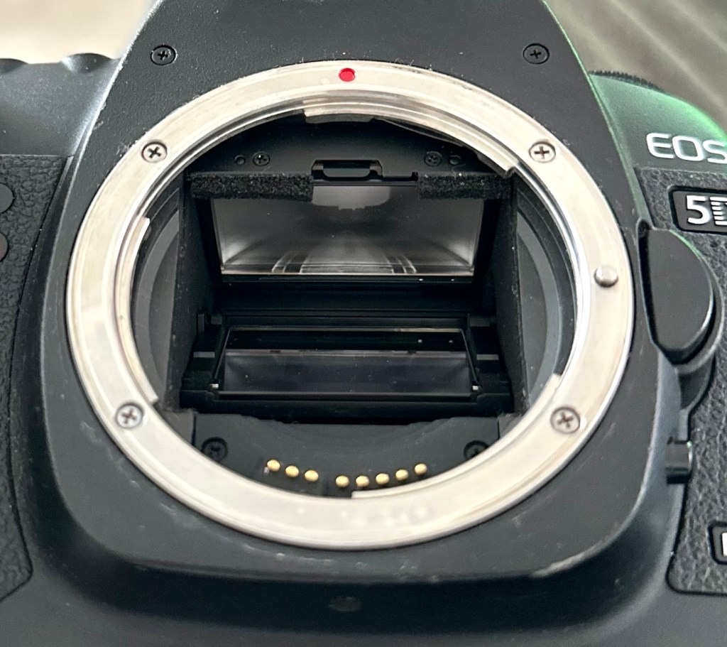
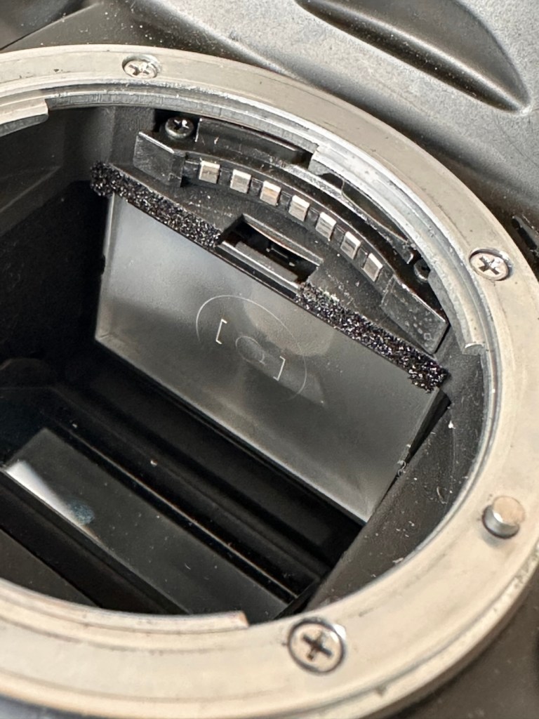
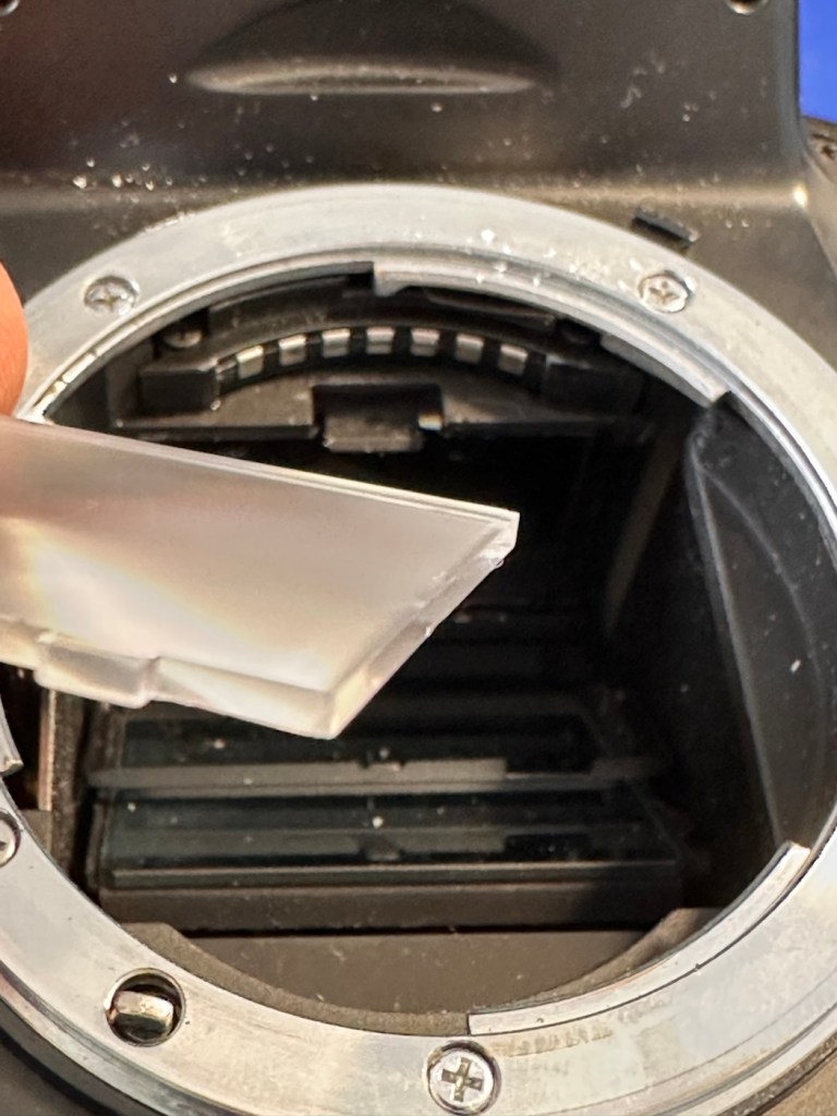
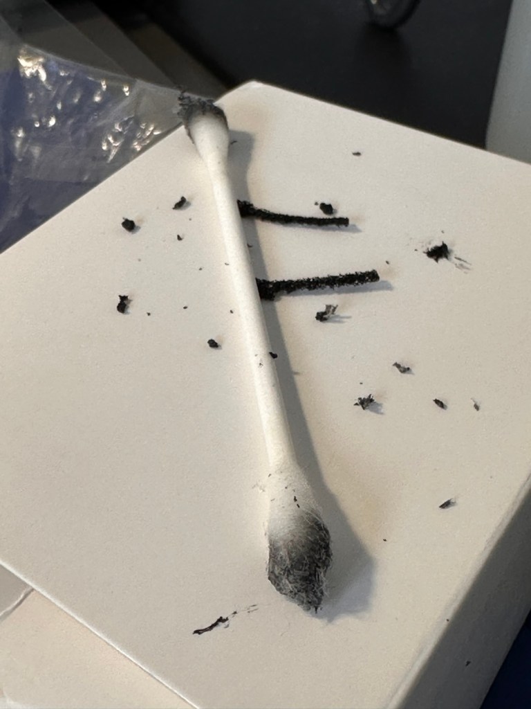
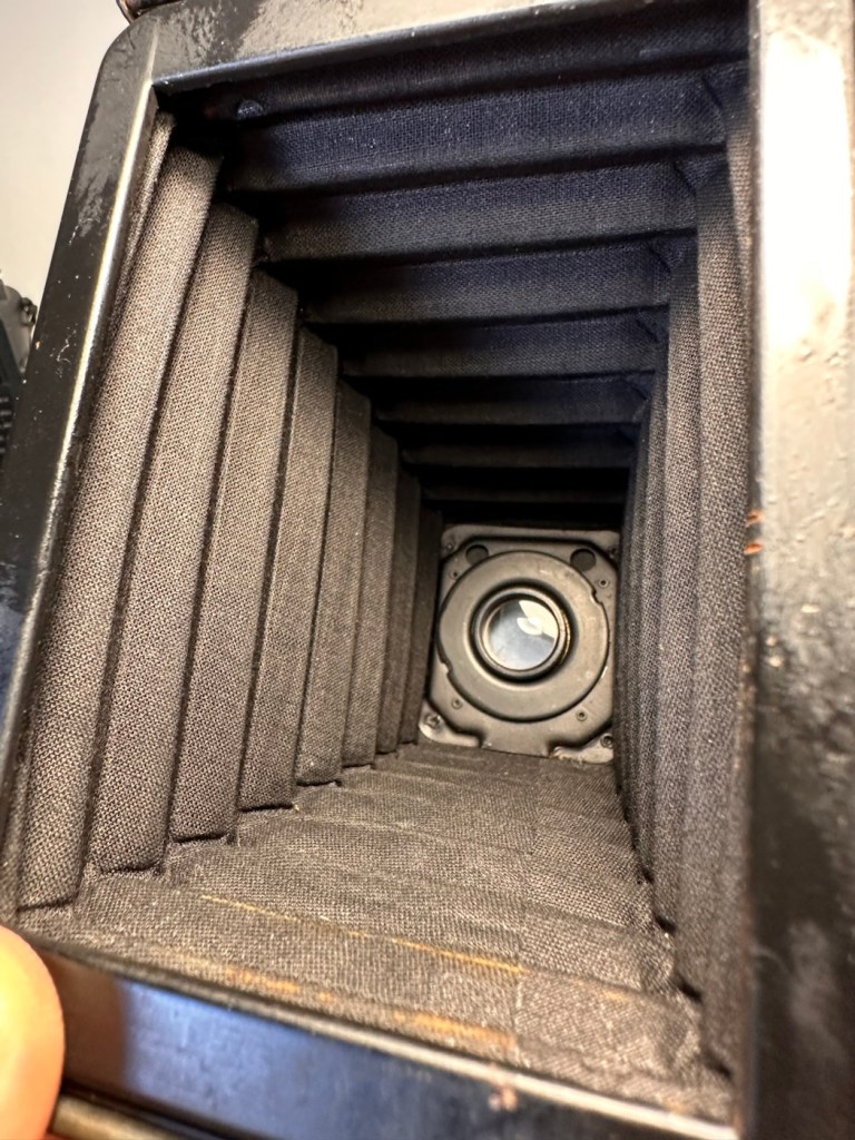
Moving on I’m looking in the lens barrel and the pentaprism and both mirror and viewfinder are extremely clean and clear. The rugged, bruised exterior has protected the delicate, clean and tidy interior. It certainly is a very well constructed camera.
The next thing I do is test the actual workings of these cameras, however that can’t be done until later today when the battery and charger that I ordered a couple of days ago arrives.
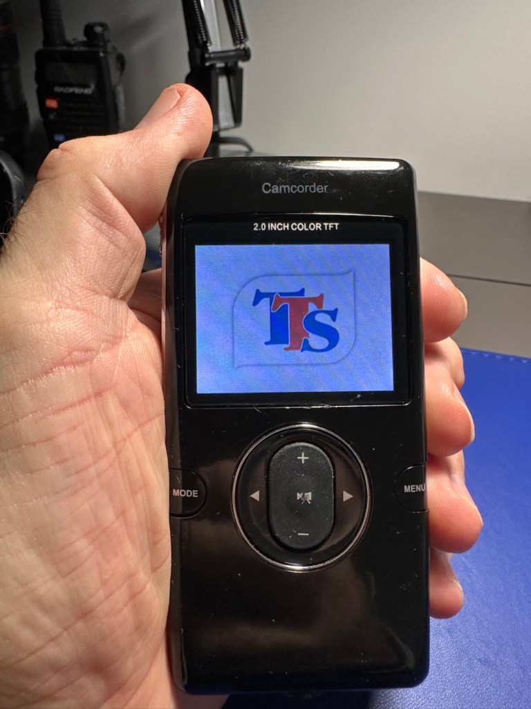
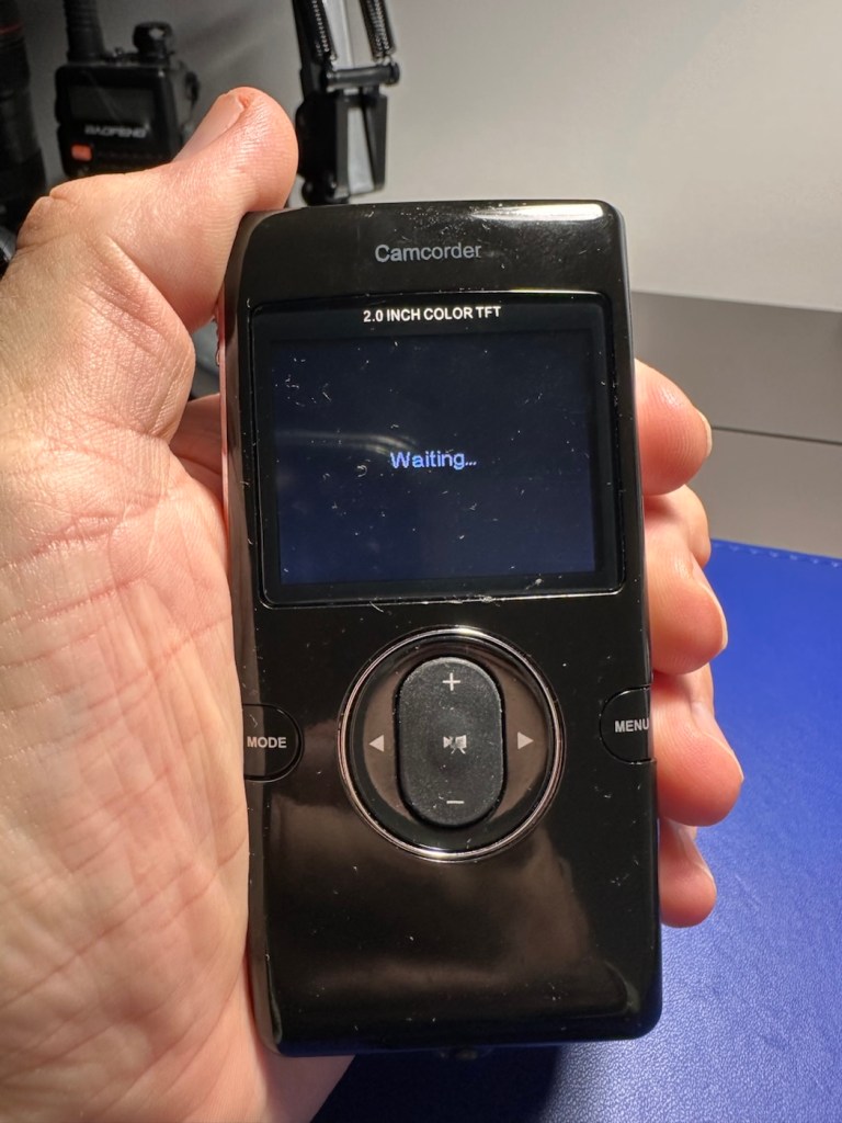
The battery and charger has arrived:
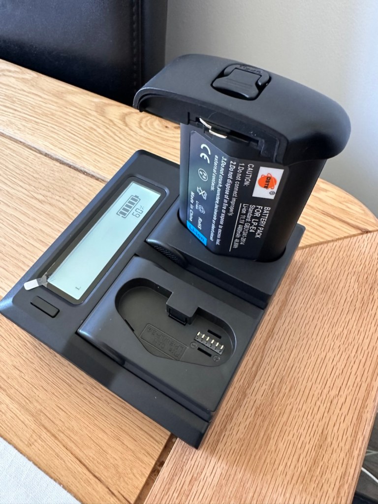
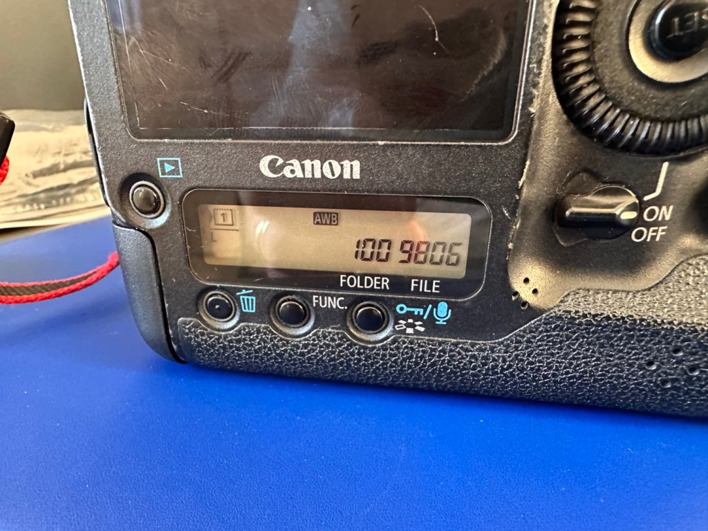
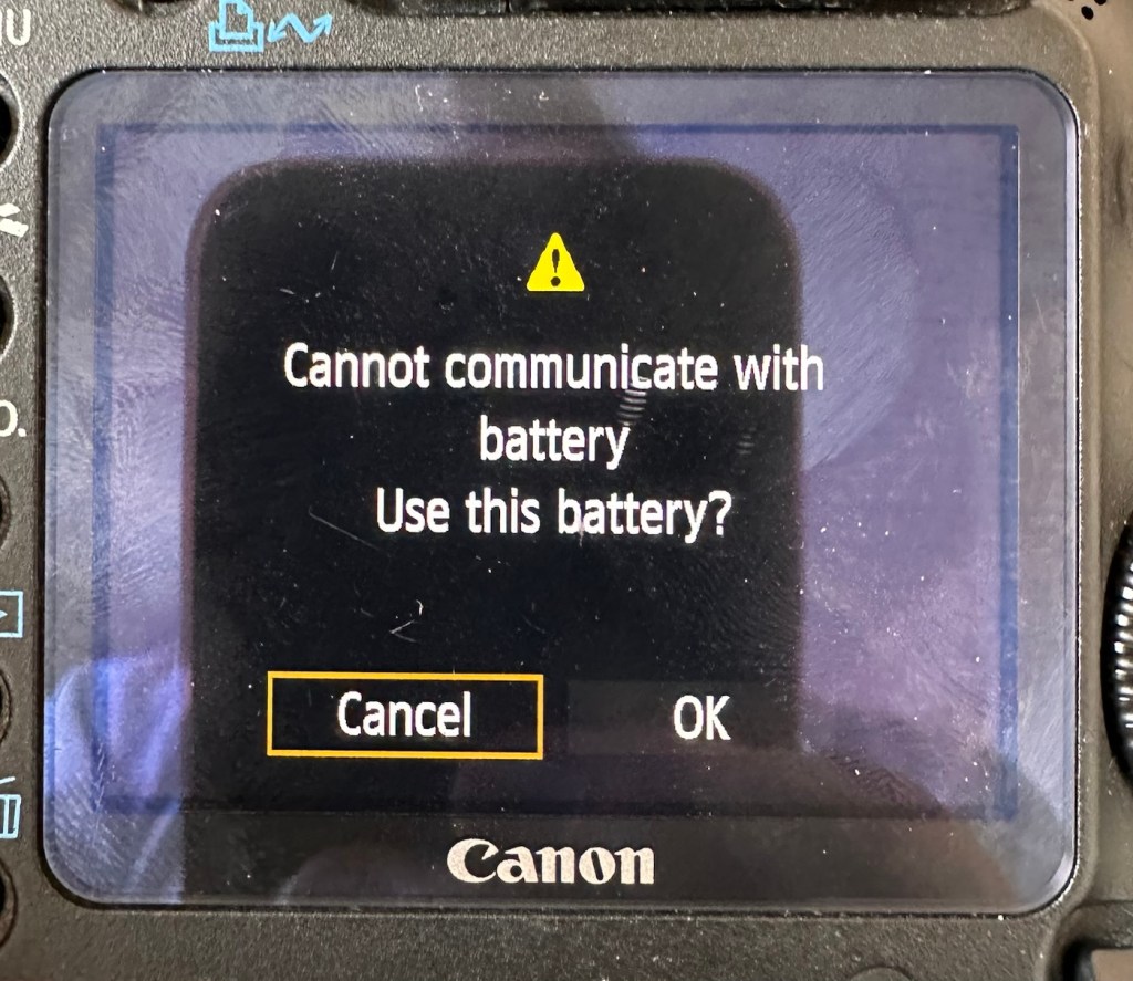
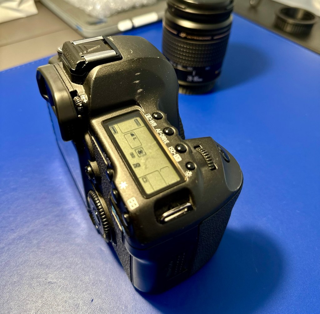
First thing I have done is to put the battery in its uncharged state, into the cameras just to see if there is life and the news is good with both. This Camera, number one has the following information.
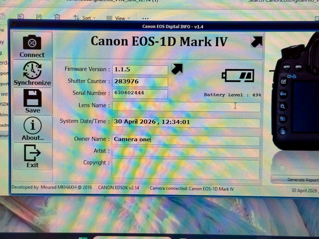
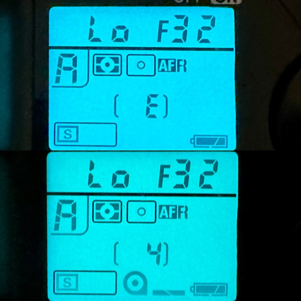
It was the most beat up camera and it does have the highest shutter count at 283,976 actuations, the shutter life cycle of these cameras is 300,000 actuations as tested by Canon, so it is a very high count but still has a bit of life in it before it reaches the potential shutter count ceiling.
The good news is that this actual camera does have the latest firmware update of 1.1.5 so at least that doesn’t have to be downloaded and installed.
Battery now fully charged I have finally been able to put this camera through its paces test wise. And hells bells I’m so impressed. It was already set in quick fire mode so when I pushed the shutter button I was shocked to see just how quick this camera responded. It was rattling off shutter actuations at a breath taking 10 frames per second, wow, the sound was amazing!
It’s not hard to see why you can get such a high shutter count on these cameras with such shutter activity, it absolutely makes sense why these cameras are used in high speed activities such as sport and wildlife photography.
All displays are working as normal, all button actions and dials are doing exactly what they should be doing. This camera is in a good healthy condition.
As an older camera it is packed to the rafters with settings and possibilities, there is so much to learn around its operation, its capabilities and settings. It’s built like a tank, weighs a ton, makes a lot of camera noise that I relate with the good old days and I just absolutely love it.
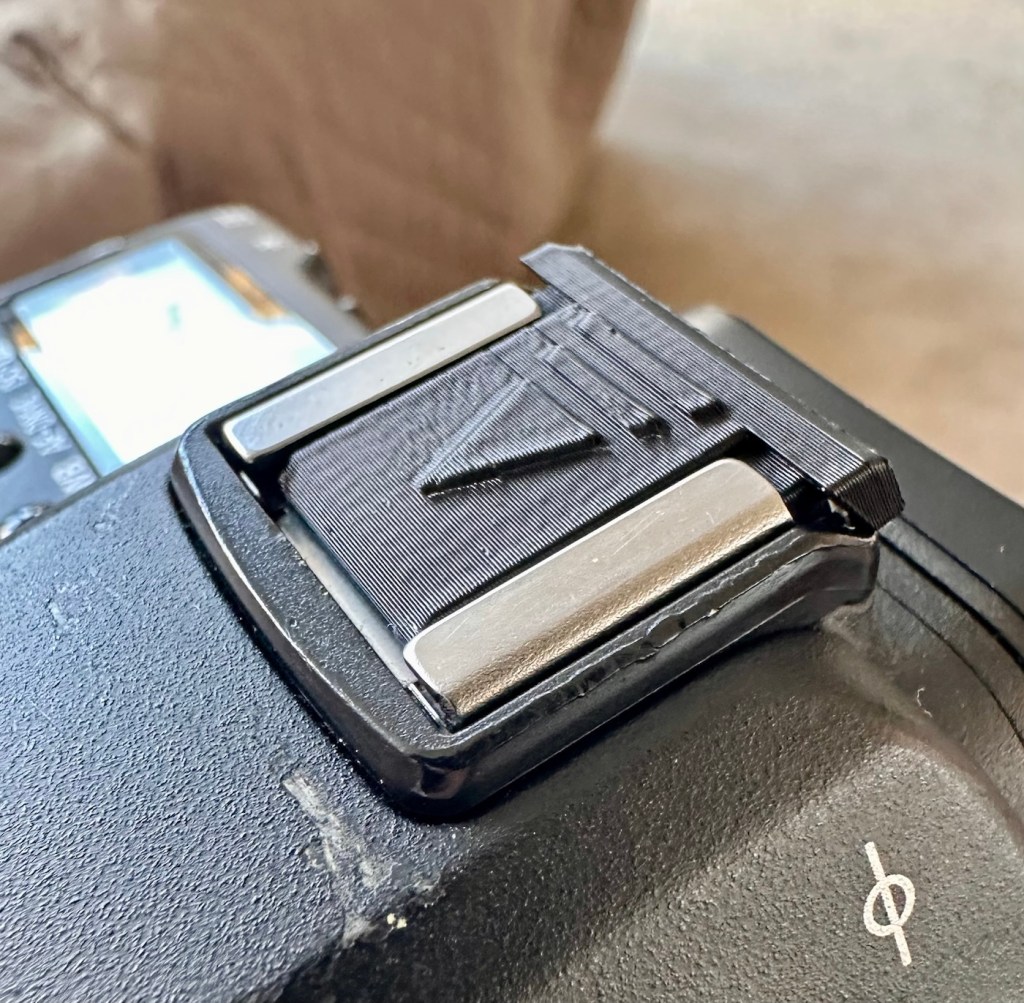
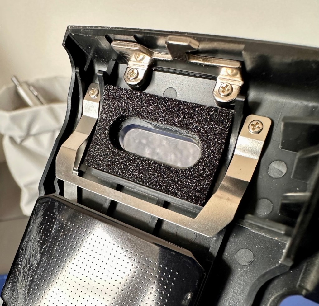
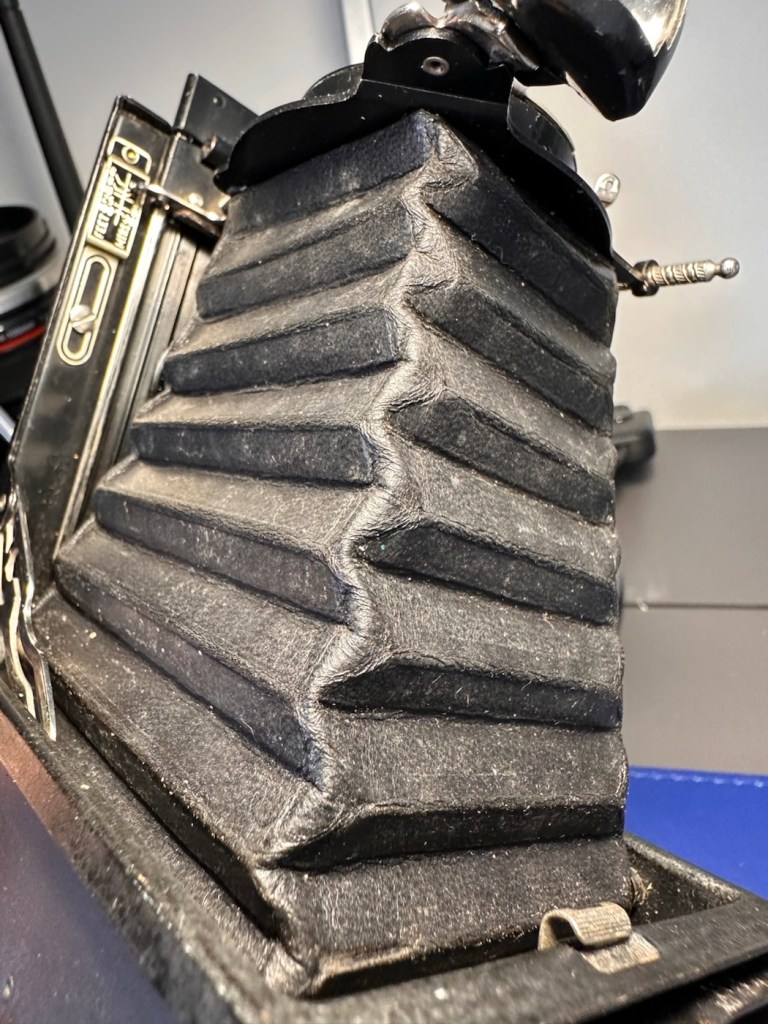
Even the shutter bumper foam is in good condition and does not require replacing yet.
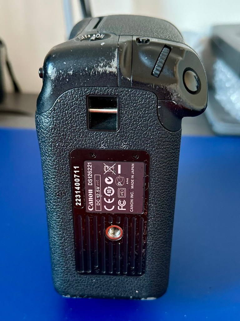
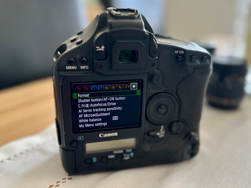
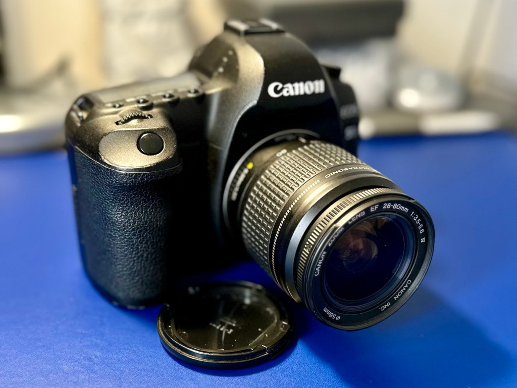
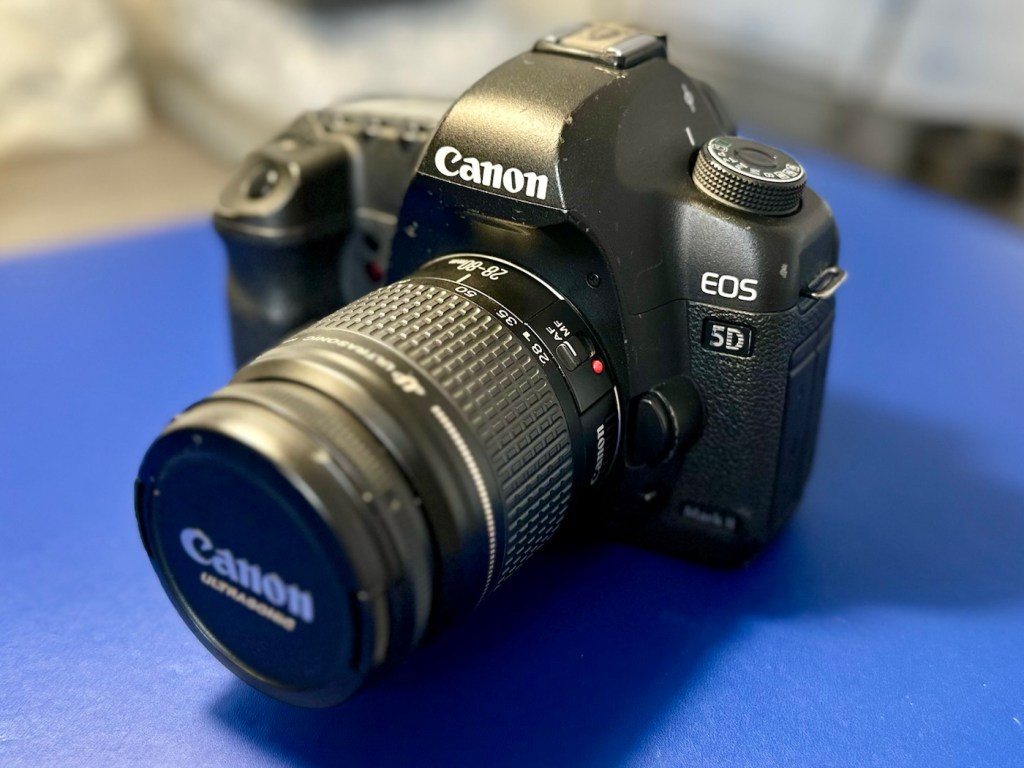
Camera two:
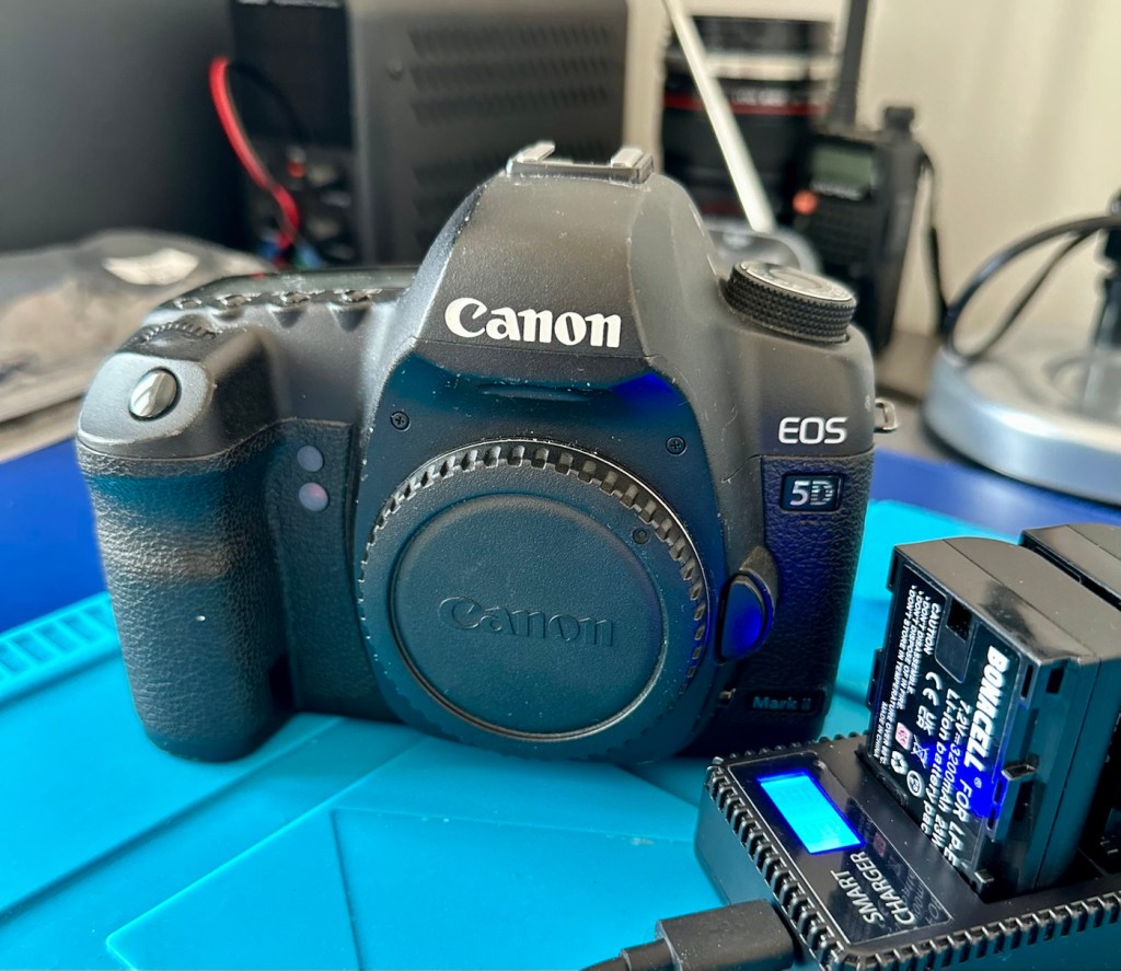
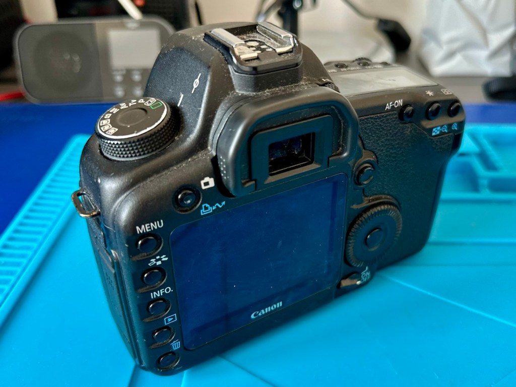
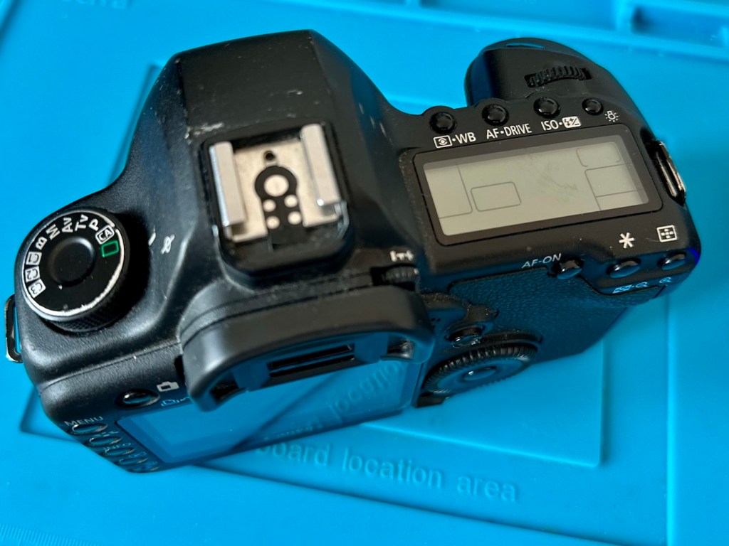
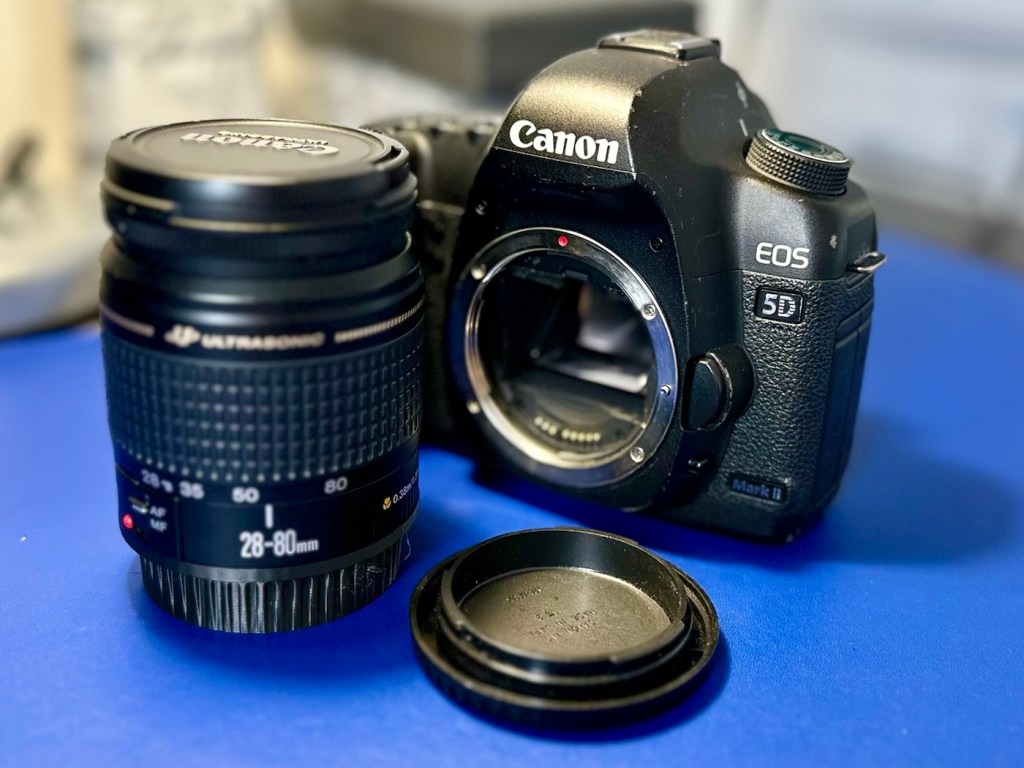
Here are the pictures:
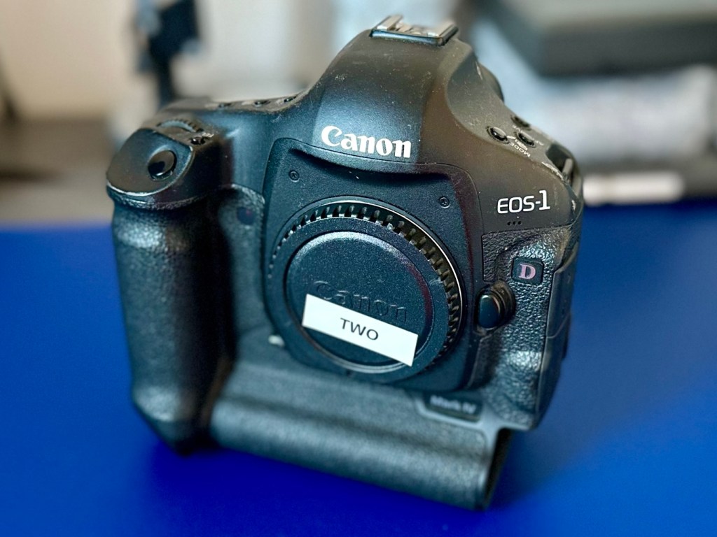
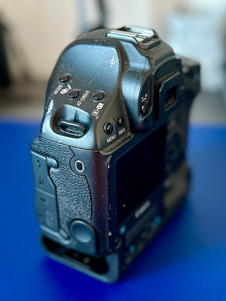
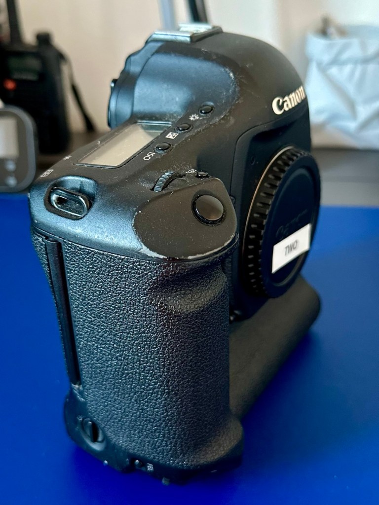
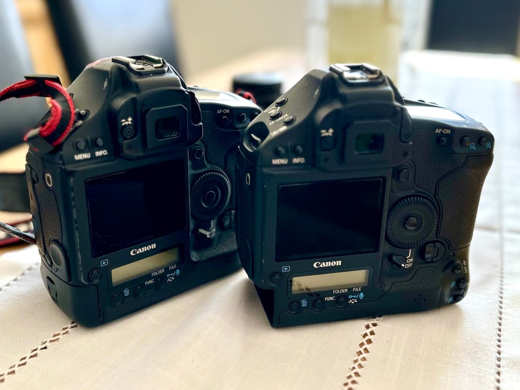
Camera two is only 16 months younger than camera one, and you can see that difference in cosmetic condition immediately. The wear and tear on this model is considerably less than that found on its counterpart. This camera had no CF card inside so there was no way of putting a last used date on this one.
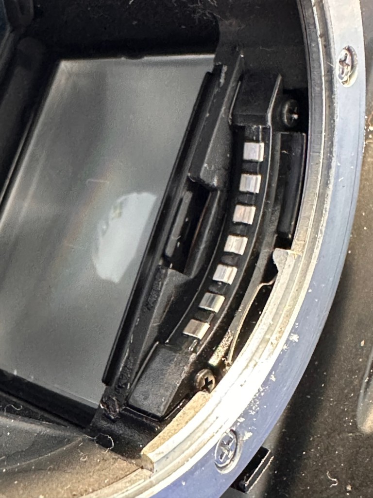
As with camera one there are no signs of the camera being dropped, no damage to the metal casing being cracked and no sharp dents visible. The Cf card and Sd card holder both take cards without any force having to be applied, and all pins are in a good order. I’m confident there are no issues in the memory card area.
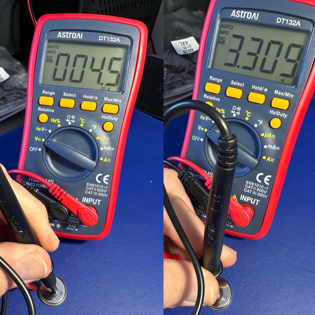
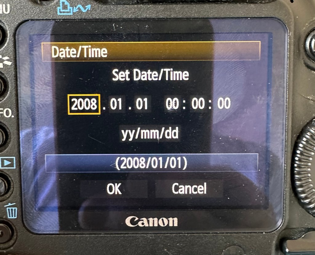
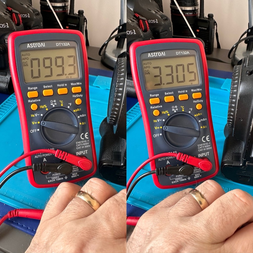
The clock battery reading is a very low 4.5mV it is very dead. I have therefore replaced this with a CR2025 3V lithium coin battery reading a lot healthier 3.30V.
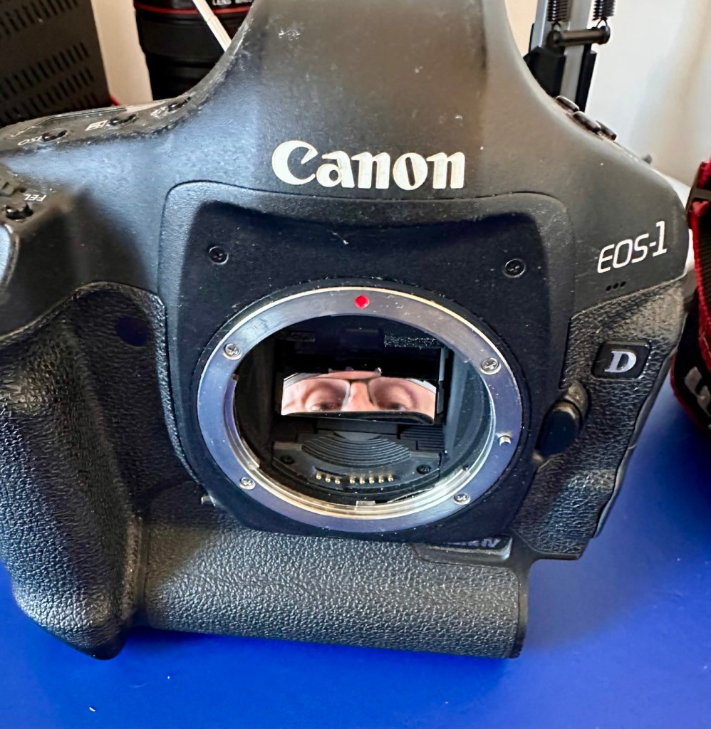
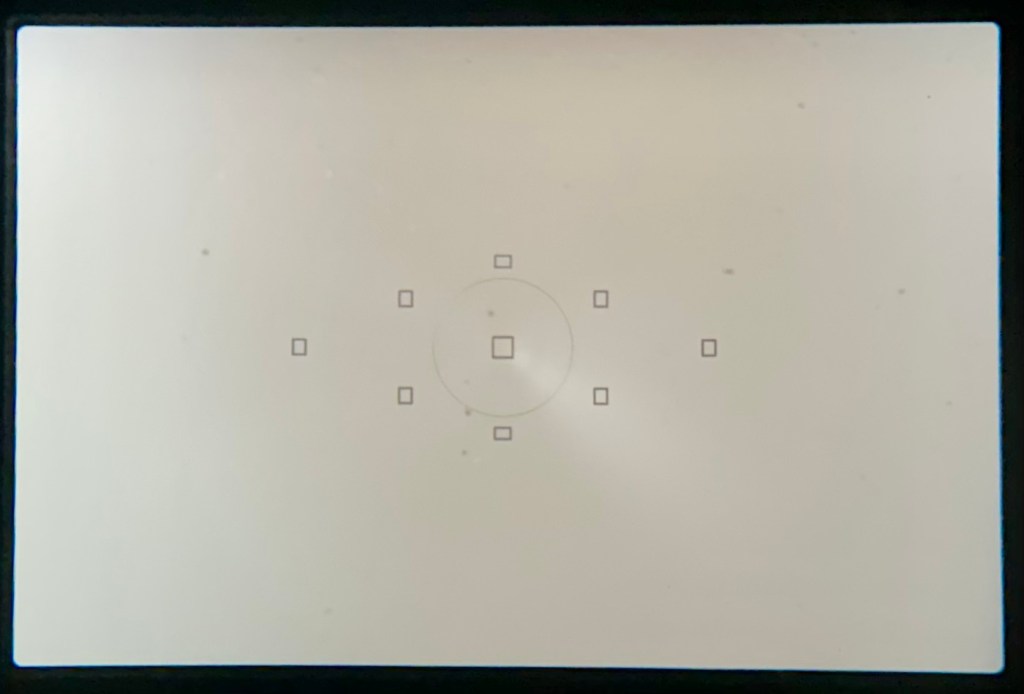
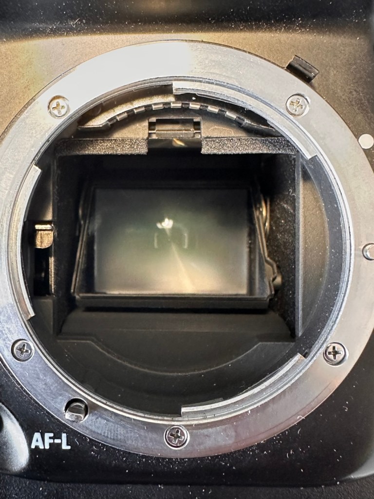
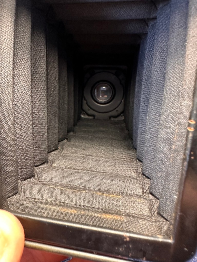
Again as in camera one, the viewfinder and mirror are both very clear and the lens barrel is very clean, having been protected by the rugged camera exterior.
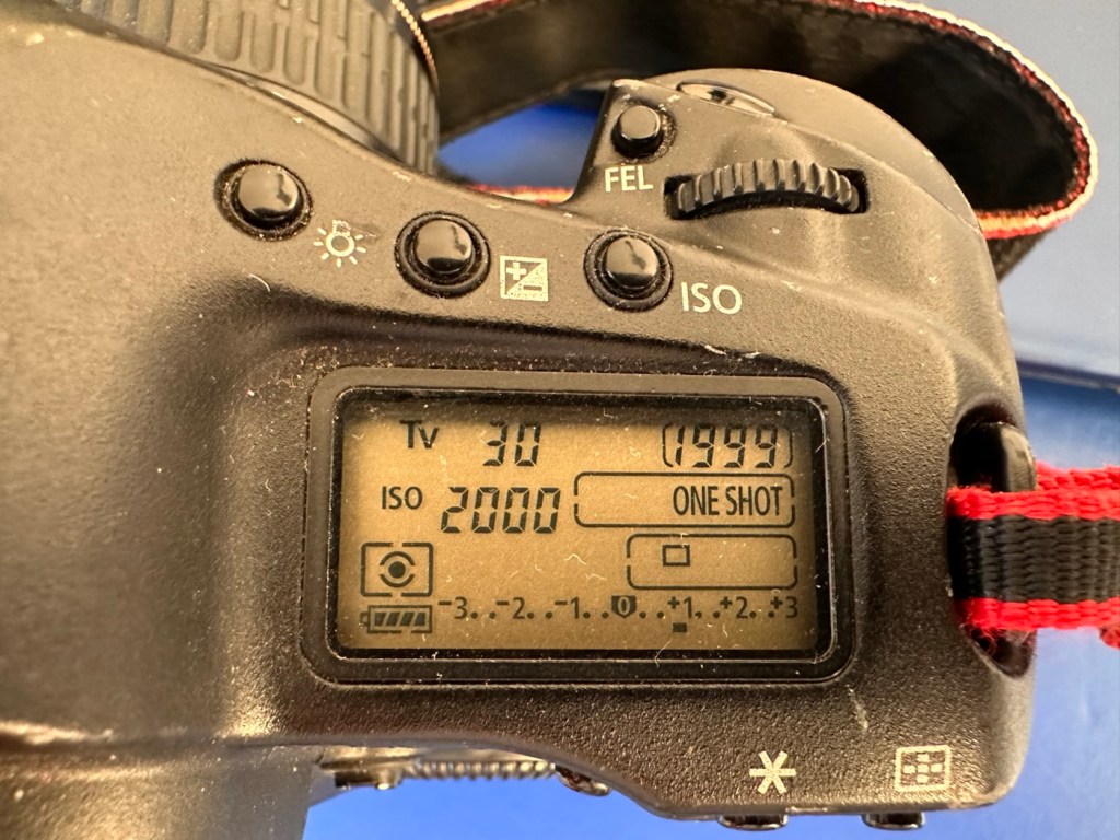
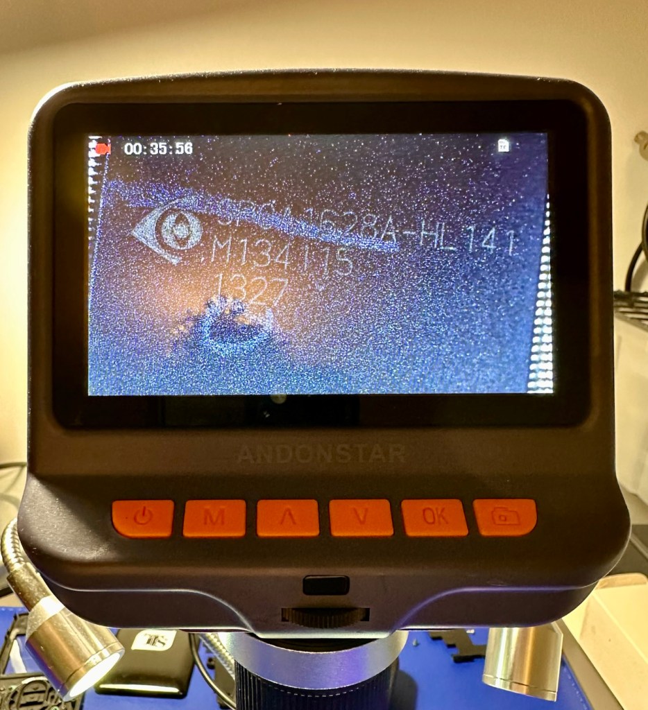
With the new battery that had just arrived installed, it kicks into life and I am then able to get the following information from the camera.
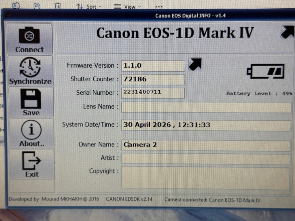
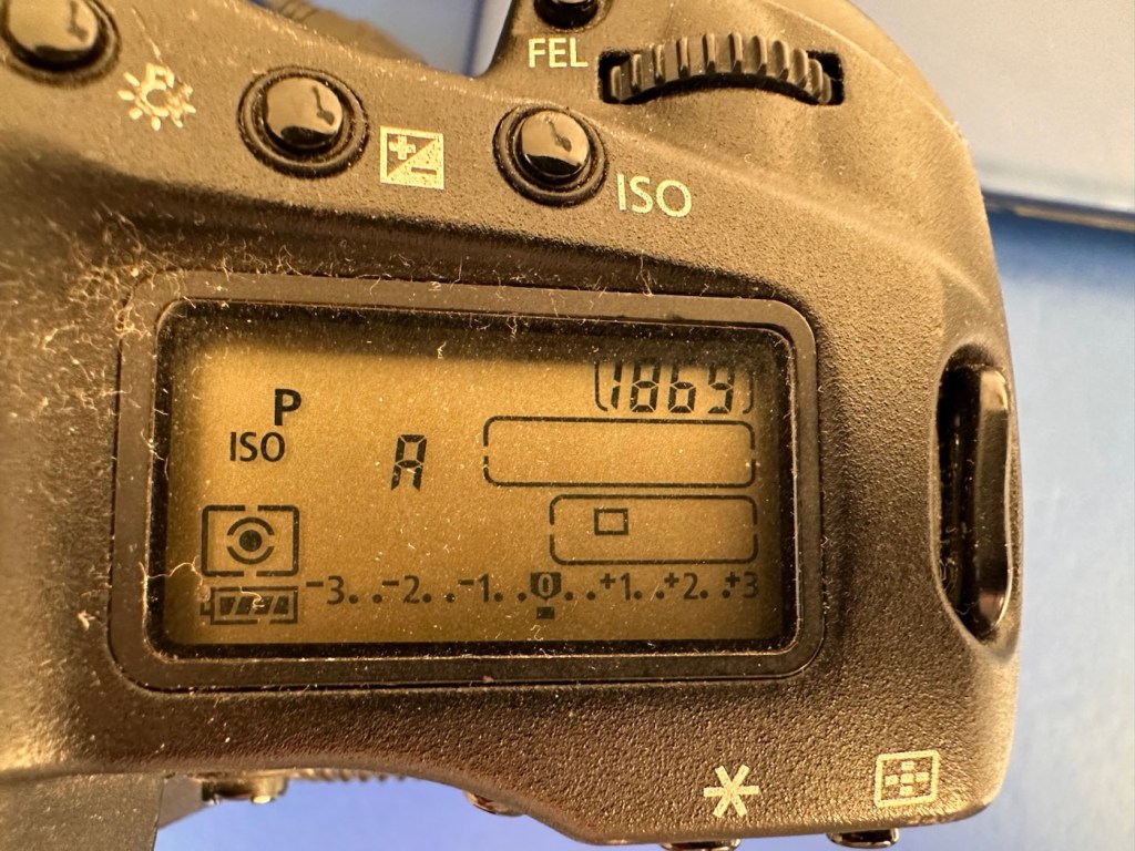
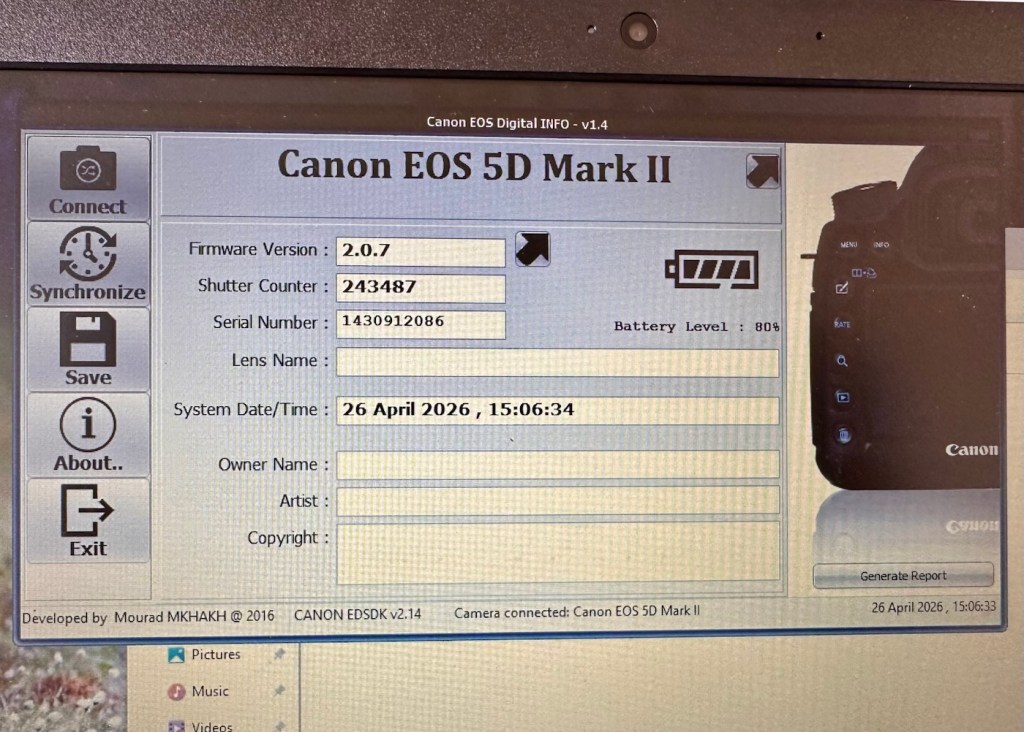
This camera in comparison to Camera one has a really low shutter actuation count of 72,186. The tested shutter count by Canon is 300,000 actuations, so this camera still potentially has a lot of life left in it.
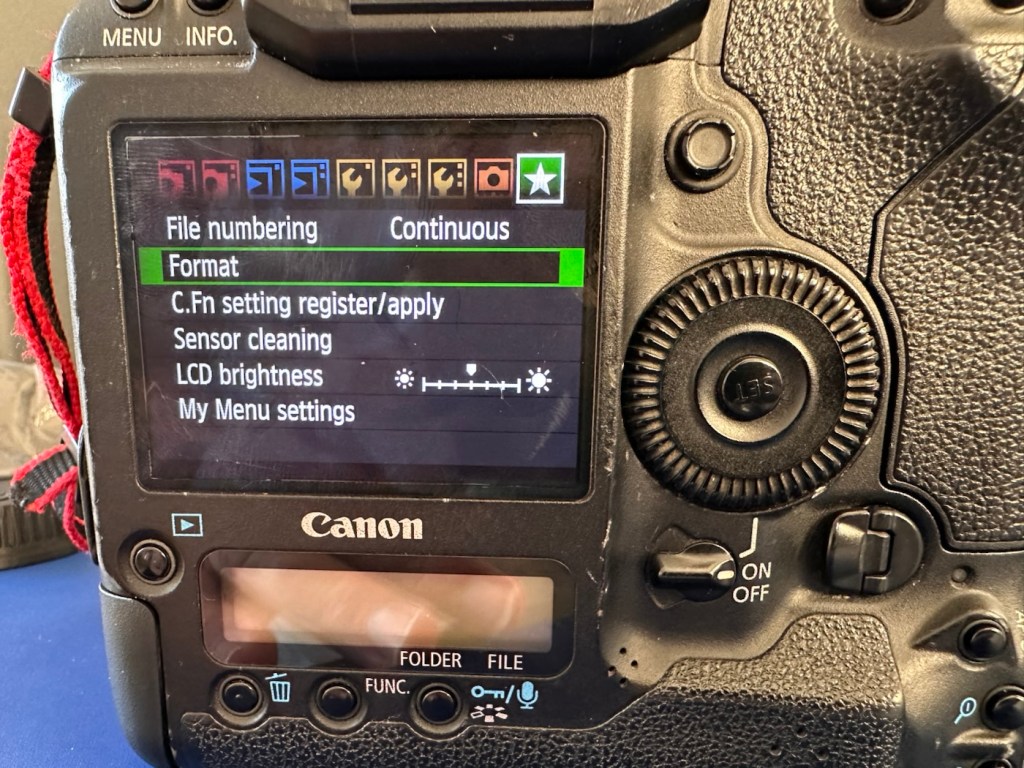
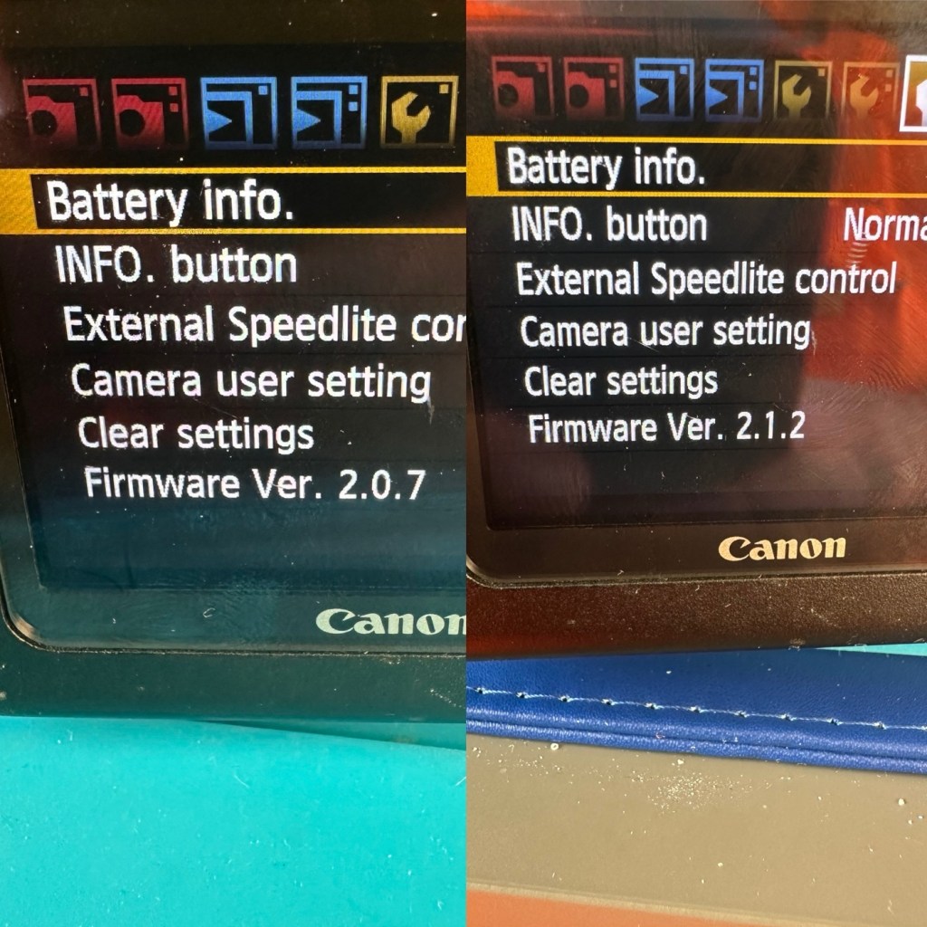
The camera firmware will need to be updated to the latest firmware of 1.1.5 as it currently has a slightly older firmware installed of 1.1.0.
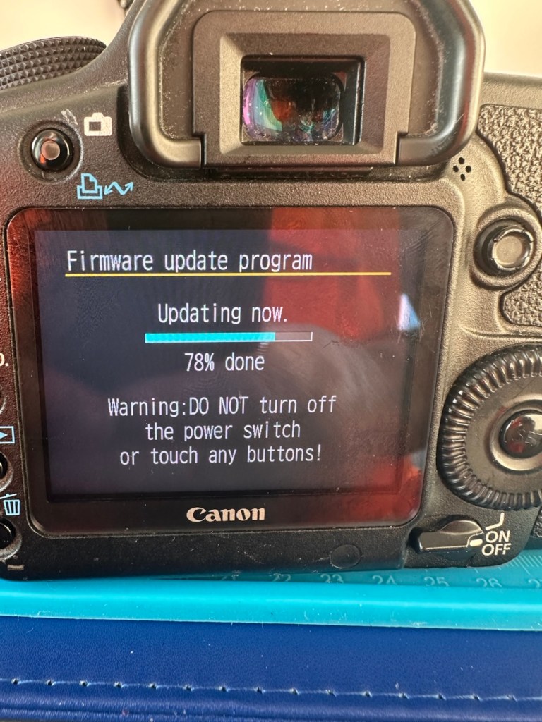
Ok, I’ve downloaded the firmware file and extracted it to the CF card I’m using in the camera. Let’s get it installed.
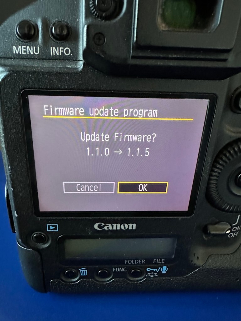
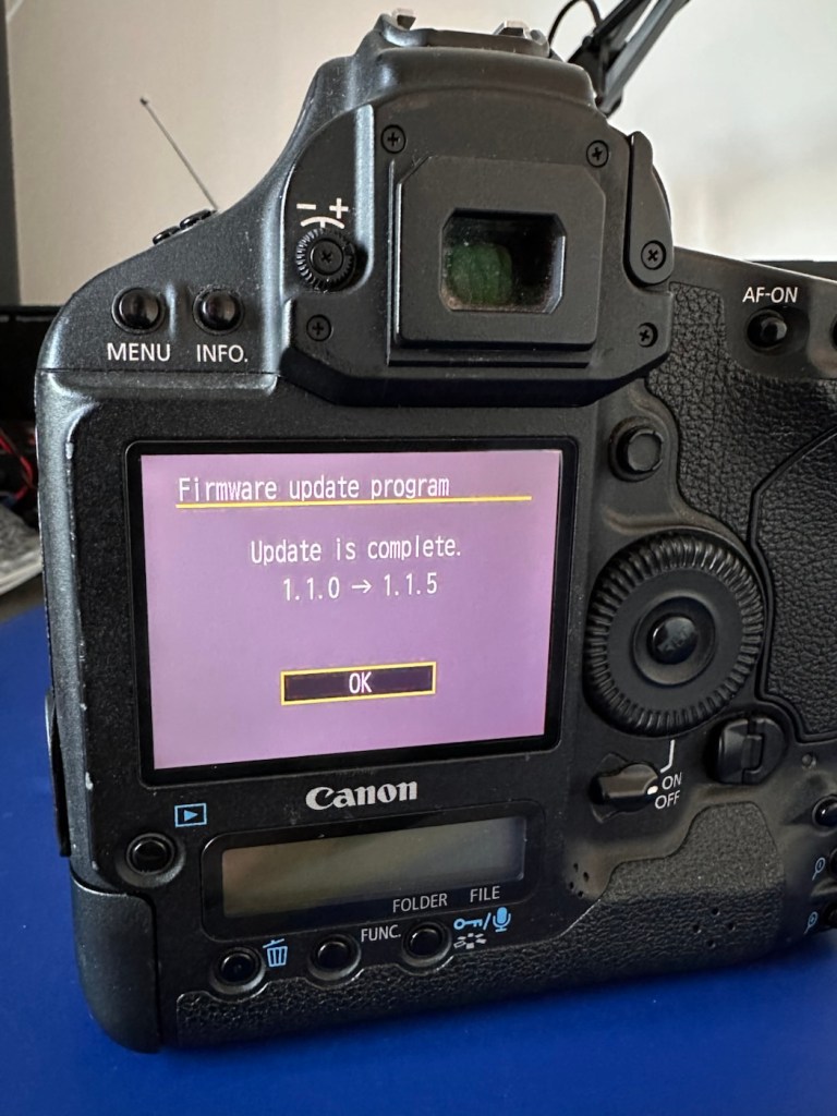
The camera firmware is now updated.
As in camera one, with the newly charged battery installed the immense high speed of the shutter is highly impressive. All buttons, dials and switches function as they should and all displays are clear and sharp in appearance.
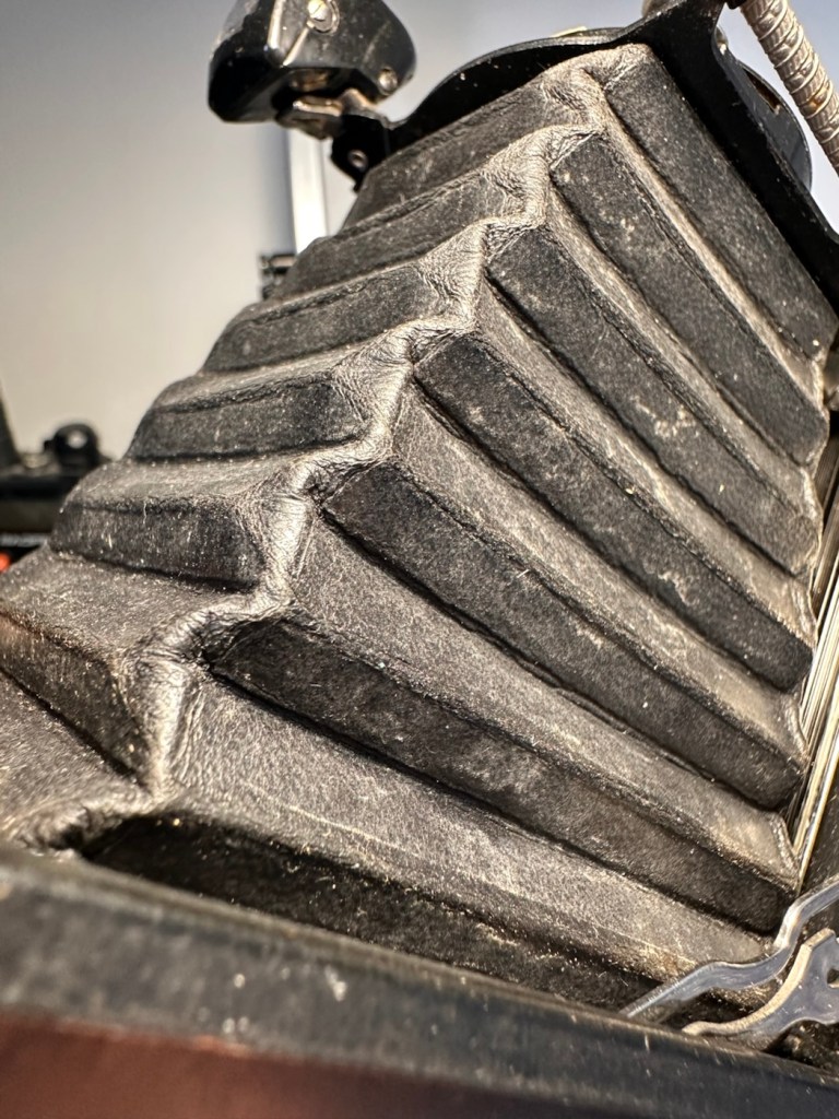
All serviceable parts remain in a good condition, even the mirror bumper foam is in a good state and does not require attention yet.
Repair:
I’m now going to condense this section into a mix of both cameras. It’s a bit of an anti climax for anyone wanting to see a meaty repair post as that’s just not going to happen here. Both these cameras, though used and in one case extremely highly used, have both been maintained and looked after during their life. So for me my job has been easy, and going forward I will just maintain them in a similar manner.

I see absolutely no point in tampering with them now, they are working just fine and are in a perfectly good condition. Their construction is so solid with their metal weather sealed bodies, that the last thing I want to do is compromise that construction and security just to fill space in a post..
All I’m going to do at this point is polish both cameras. Camera one with its beaten up body and press pass stickers is just going to stay like that, I want that to remain as a constant reminder of its use, and its purpose as a high usage press photographers camera, it’s a work of art in itself and that’s how it will stay. Camera two, again will jut be polished, it’s the more acceptably presentable “Cosmetically” camera and with its lower shutter count and will probably be the unit i will concentrate on using myself.
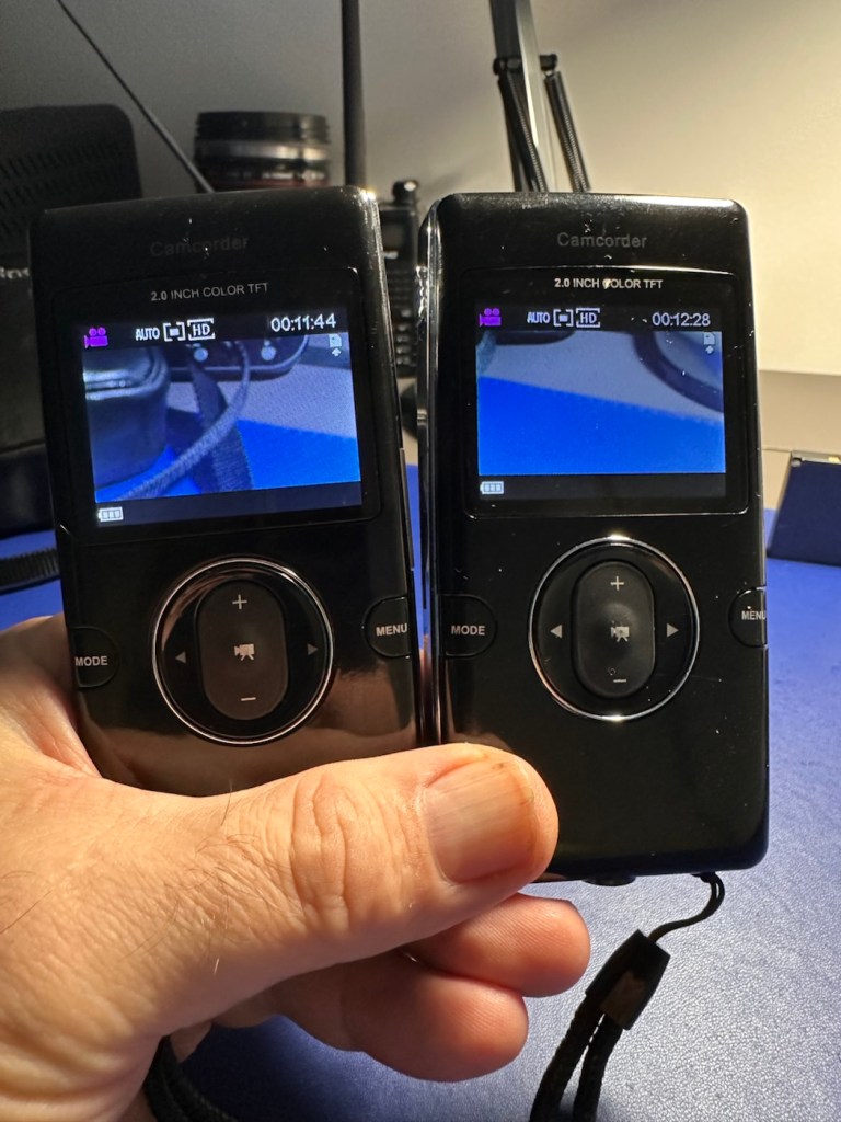
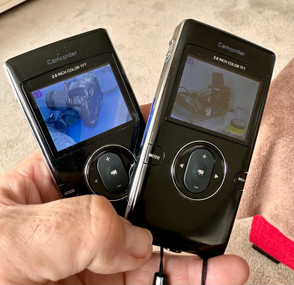
A few pics from the two of them:


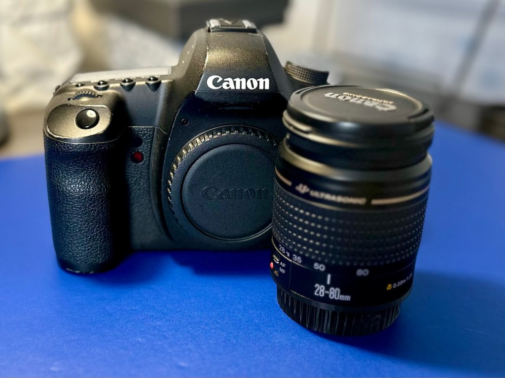
I’m only using very basic test lenses on these units and I must admit, even with basic optics the visual returns are quite impressive. The colours are so rich, and I love that there is also the setting to do some pure black and white shots if you so wish.
This is my new (Old) favourite camera. Why do I just fall in love so easily ❤️
When these cameras first came out they were commanding a price of around £4,000.00GBP and people were more than happy to pay that cost.
Here I am a few years later and I have been gifted two of them for the grand old price of…..Nothing.
I’m a lucky old fellah I’d say.
Result:
I present to you, two wonderfully heavy, cumbersome, noisy and beautifully constructed pieces of photographic history, and both are an absolute joy to behold.
My new long term relationship has just begun (Don’t tell the wife 😂) and I am so looking forward to getting these cameras out to a sports or wildlife watching event. To many, I know they will say, why do you want to carry one of those around, why not go mirrorless? Well, I’ve got that gear as well but I hardly use it. I’m an old 80s-2000s guy who loves the old technology, just like I love old noisy aircraft, I love to hear a camera working, it puts a smile on my face. And the chances of me owning one of these beauties when they first came out was an absolute zero. Now I have two, and I have some serious catching up to do.
Thanks for passing by, as always it’s very much appreciated.
Stay safe.


You must be logged in to post a comment.